Article

Effect of HIP Defects on the Mechanical Properties of Additive Manufactured Ti6Al4V Alloy

1
Faculty of Mechanical Engineering, Technion, Haifa 3200003, Israel
2
Department of Materials Engineering, Ben-Gurion University of the Negev, P.O. Box 652, Beer-Sheva 8410501, Israel
*
Author to whom correspondence should be addressed.
Metals 2022, 12(7), 1210; https://doi.org/10.3390/met12071210
Submission received: 7 June 2022 / Revised: 12 July 2022 / Accepted: 13 July 2022 / Published: 17 July 2022
(This article belongs to the Section Additive Manufacturing)

Abstract

:
The expanding use of Additive Manufacturing (AM) technology enables engineers and designers to plan and manufacture highly complex geometries that are impossible to manufacture with any other conventional technology. When comparing this with building parts using powder bed technology, the main differences found in the quality of the products concern fracture toughness, fatigue, and inferiority in tensile tests. To overcome these issues, the Hot Isostatic Press (HIP) procedure may be used to improve the material quality by reducing product porosity. Regarding fatigue, the standard procedure consists of HIP and the machining of specimens to their final geometry. However, in many AM parts, geometrical complexity does not enable complementary machining. Recently, some AM vendors integrated in-process milling capabilities into their machines, in an attempt to address this challenge. In this study, the authors examine the effect of the HIP procedure on representative samples in order to demonstrate its effect on the final products of TI-6Al-4V parts. The results indicate that the fatigue limit of HIPed parts can increase by 12%; however, a dramatic decrease in the fatigue limit was observed if any failure in the HIP process occurred. The authors suggest an optional procedure to improve performance in such cases.

1. Introduction

The high strength and the high specific strength of Ti-6Al-4V alloy at moderate and elevated temperatures, along with its excellent corrosion resistance, have led to its extensive use in the automotive and aerospace industry sectors [1,2,3]. Mirgal et al. [4] describe titanium as “the metal for the 21st Century” due to its superior strength and density in comparison to other materials used in the automotive industry. This extensive use of titanium has contributed to its implementation within AM technologies. The variety of AM processes and technologies (for example: powder bed fusion (PBF), laser bed fusion [5,6], electron beam AM (EBAM) [7,8,9], powder deposition (PB) [10], wire deposition [11,12,13], etc.) are promising new methods for extremely complex geometries [14,15,16]. The use of AM technology was first regarded as a rapid prototyping technology aiming to assist engineers in design and to speed up product development on the path to production. Over time, AM technologies have emerged and matured, demonstrating process advantages along with superior physical and mechanical properties. Interest in AM technologies has increased along with the demand for final parts. While the standards for conventionally manufactured TI-6Al-4V part tensile properties [17], fracture toughness [18], fatigue performance [19] and other properties are familiar and satisfy guidelines for testing, only a few standards are available for AM parts, and they are still under development via ASTM F42 committees [20,21]. Beretta and Romano [22] performed a comprehensive literature review comparing AM products with those produced using traditional manufacturing processes; they emphasized the fatigue properties of AISi10Mg and Ti-6Al-4V and the apparent sensitivity with regard to defects and inhomogeneity in AM parts. Wycisk et al. [23] presented a simulation and analysis of crack propagation and fatigue results on defective samples with porosity and surface defects. They showed that the endurance limits of the as-built samples were significantly lower than for polished specimens. Ganor et al. [24] and Tiferet et al. [25] used a powder bed electron beam melting technology for Ti-6Al-4V and performed HIP according to ASTM F2924 [26]; they showed an increase in the bulk density and a drastically improved elongation by almost 200%, with a slight decrease in the yield and ultimate strengths. Previous investigation into fatigue data for SLM and EBM Ti-6AL-4V was summarized by Quintus Technologies AB and Oak Ridge National Laboratory [27] and relayed in Leuders et al.’s study [28]. The HIPed specimens’ fatigue limit was significantly improved from below 300 MPa to 550 MPa at 107 cycles. Günther et al. [29] reported that the HIP process improved the fatigue performance of EBM and Selective Laser Melting (SLM), and it was similar to that of a conventional Ti-6Al-4V material. Sanaei and Fatemi [30] published a comprehensive review on defects in the AM of metals and their effect on fatigue performance; they observed that the pore size and location affect fatigue life and that for “machined surface specimens, defects dominated the fatigue performance and by reducing defects after HIP microstructural inhomogeneities mainly affected the fatigue performance”. Fracture toughness is another key factor in understanding the qualities of the material and the parts. Horiya and Kishi [31] studied the fracture toughness of conventionally manufactured titanium alloys and set guidelines for improving the fracture toughness. They reported that, for the same titanium alloys, the KIC value widely varies at the same tensile strength and generally improves with coarsening microstructure. Dhansay et al. [32] studied the fatigue and fracture toughness and crack propagation of Ti-6Al-4V in SLM samples at two orientations. They indicated that with stress-relieving heat treatments, the fracture mechanics parameters of fatigue and fracture toughness had a strong correlation between conventional Ti-6Al-4V and SLM samples produced with EOSINT M280. The fracture toughness outcome of Dhansay et al. is higher than for the data reported by Hooreweder et al. [33].
In this study, the influence of post-processing on parts made by Ti-6Al-4V manufactured by an AM SLM technique was investigated. The paper focuses on the effect of the HIP process and its role as a key factor for reducing defects and improving fracture toughness and fatigue limits. The experimental procedure and the results of various post-processing operations are explained in detail to emphasize the importance of the final manufacturing procedures and their possible effect on the final products.

2. Materials and Methods

Specimens of Ti-6Al-4V alloy were built by direct metal AM (DMLS) using an EOS M280 powder bed machine (EOS, Krailling, Germany) equipped with a 200 W Nd-YAG laser with a beam diameter of 80 microns. The samples were fabricated using 30-micron layers of TI-6Al-4V powder with a size distribution between 20 and 63 microns. All specimens were produced by adopting standard parameters given by the machine manufacturer, and were manufactured along the Z-direction according to the ISO/ASTM52921-13 standard [21] with the aim of examining the critical direction of the parts. The chemical composition of LPW powder shown in Table 1 was analyzed by X-ray fluorescence (XRF) (ARL PERFORM′X, Thermo Fisher Scientific, Waltham, MA, USA) for the metal’s compositions and inert gas fusion (IGF) (LECO, St. Joseph, MI, USA) for hydrogen quantitative content of gases. The composition is similar to ASTM F2924 [26].
The parts were stress-relieved by heat treatment at a temperature of 650 °C for 3 h under a 5 × 10 5 [Tor] vacuum atmosphere prior to their separation from the Ti-6Al-4V base plate. In order to evaluate the influence of the HIP treatment on mechanical properties, the specimens were divided into two groups—the first was left as it was, and the second was HIPed. Tensile, fracture toughness, and fatigue test specimens were machined to the desired geometries out of the first group as follows: (Figure 1a—tensile samples in accordance with ASTM E8 [17], Figure 1b—Compact-Tension (CT25) specimen in accordance with ASTM E399-17 [18], and Figure 1c—fatigue samples following ASTM E466 [19]).
The second group of specimens were HIP-treated in a 1000 bar under argon environment for 2 h at 920 ± 10 °C with a controlled up-and-down temperature slope, as shown in Figure 2. The temperature of 920 °C is in the middle of the recommended range of the given standard [24]. In addition, according to previous studies that examined the influence of the HIP temperature on the mechanical properties, the recommended HIP temperature is 920 °C with 2 h 1000 bar [24,25]. The tensile and CT25 samples were then machined, while the fatigue samples were machined after the HIPing process in order to be correlated with the final complicated AM parts. A schematic illustration of the sample preparation is shown in Figure 3.
The tensile tests were performed for as-built stress relief samples, and after HIP, 3 samples were tested. The tensile test was carried out according to ASTM E8/E8M-16a Standard Test Methods for Tension Testing of Metallic Materials at 24 °C temperature, using an Instron 8802 testing machine (250 kN loadcell) and an Instron 2620-602 extensometer. The tensile test crosshead speed was 1 mm per minute. The elongation was measured on 25 mm (about 4 times the diameter of the specimens).
All fracture toughness tests were carried out according to the ASTM E399 Standard Test Method for Linear-Elastic Plane-Strain Fracture Toughness KIC of Metallic Materials. The test includes fatigue crack initiation and propagation from a notch and static loading up to fracture, including determination of the fracture load. The pre-cracking loading was carried out using an Instron 8801 testing machine (Dynacell, Dynamic Load Cell +/− 100 kN) under load control with a sinusoidal waveform in air at 22 ± 3 °C and at 15 Hz frequency. The cyclic loading of the fatigue pre-cracking was applied with the load ratio R = 0.1 and a maximum load of 3 kN (200–500 K cycles). The maximum stress intensity in the terminal (2.5 %) stage of fatigue crack growth did not exceed 80% of the estimated KIC of the material. The crack propagation was monitored using a crack opening displacement gage (COD gage) and by visually examining crack growth on the sides of the specimens. Two sets of compact type CT25 samples were prepared and tested for mode I fracture toughness: the as-built stress relief and HIPed specimens. In both cases, the final machined geometry was carried out prior to the tests and complied with the ASTM E399 standard [18]. The specimen notches were parallel to the built plate and perpendicular to the building direction, in order to examine the weak direction of the parts.
The fatigue sample preparation (according to ASTM E399-17) included building cylinders, heat treatment, and machining to the final geometry (as shown in Figure 1). The loading cycles were chosen and the fatigue loading was activated. In this process, the external surface was removed prior to testing. In this procedure, the built material was examined without any other interference. In this study, the authors intended to evaluate additional defects that might influence the fatigue limits of the built specimens due to the HIP process. For this purpose, a set of samples was prepared and tested according to the ASTM E399-17 [18] standard. The fatigue test was performed according to the ASTM E466-15 [19] standard with a focus on the high cycle section. A force-controlled constant amplitude uni-axial loading was carried out using an Instron 8801 testing machine (Dynacell, Dynamic Load Cell +/− 100 kN) under load control with a sinusoidal waveform. The specimens were fixed using Instron fatigue-rated hydraulic wedge grips and cyclic loading was applied with the load ratio R = 0.1. The cyclic loading was carried out in an atmospheric environment at 23 ± 2 °C and 25 Hz frequency up to 10 7 loading cycles or until failure occurred. The cyclic loading was performed at several loads to obtain the fatigue curve and fatigue limit.
To explore the mechanical properties of the final product with or without the HIP, several samples were produced and tested for fatigue life limits:
  • As built (stress relief and machined);
  • HIPed and machined—a common procedure according to the fatigue standard;
  • Machined and HIPed—to resemble complex geometries that cannot machined after being built.

3. Results and Discussion

3.1. Tensile Tests: Tensile Properties Were Measured in the Build Direction

The tensile test results are shown in Table 2. The as-built stress relief and the HIPed samples are satisfactory and coincide with the ASTM F2924 [26] standard for Ti-6Al-4V. When comparing the as-built and HIPed samples, the HIPed elastic modulus and yield strength were shown to decrease, but are within the standard deviation of the ASTM requirement, while the elongation and reduction in area increased.

3.2. Fracture Toughness

The calculated fracture toughness is given in Table 3. It is noted that the average crack size is calculated from five locations in each sample. The average crack size was measured by SEM, as shown in Figure 4.
The as-built stress relief (vacuum-treated at 600 °C for 3 h) fracture toughness is similar to that of Ti-6Al-4V grade 5 material in STA condition as a result of the α’ phase microstructure of the built material, due to the rapid solidification in the process. The HIPed samples (1000 bar argon environment for 2 h at 920 °C) pass a recrystallization process, annealing the material and increasing the fracture toughness to more than that of a conventional annealed plate. Similar results were presented in [34,35].

3.3. Fatigue

HIPed samples and defects—In general, HIP is used to improve material quality and to extend the fatigue life of cyclic loading parts and structures. One of the advantages of the AM process is its ability to relatively easily manufacture an extremely complex shape that is difficult or impossible to manufacture with other conventional technologies [36,37]. Complex geometries do not enable the entire part to be machined; therefore, some surfaces remain with their as-built roughness and might contain a stress concentration that reduces the fatigue limit of the working part compared to the standard test samples. This effect has been tested and reported in the literature [22,38,39]. The effect of the built surface on tensile strength was reported by Dzugan et al. [40] and the effect on fatigue performance was reported by Greitemeier et al. [41] and Sanaeia and Fatemi [42]; they showed that the surface roughness has a high effect and reduces the fatigue limit.
The test results of these samples are presented in Figure 5 and compared to those in the published data of Wycisk et al. [23]. For standard Ti-6Al-4V laser powder bed AM machine samples, the achieved endurance limit of the current study was 570 MPa, while the value presented by Wycisk et al. was 500 MPa for polished specimens. Only 210 MPa was achieved for “as-built” samples (without surface removal). The enhanced limit is significantly lower due to surface crack initiation. Kasperovich et al. [39] compared the fatigue results between as-built HIPed samples to HIPed and machined samples; they indicate a large reduction in the fatigue loads and cycle of failure due to the surface roughness. In some AM technologies, the part can be machined to the final geometry during the built operation. An example for hybrid AM, including subtractive processes, is given in [43,44].
The fatigue life and maximum stress of the three types of sample are shown in Figure 6; as expected, the HIPed and machined samples reach the highest fatigue limit of 707 Mpa, the as-built stress relief and machined samples achieved a fatigue limit of 570 Mpa, while the HIPed and machined failed at lower loads and low cycle fatigue.
The failed HIPed and machined samples were examined via SEM micrography to evaluate their failures. The microstructure of a typical HIPed and machined sample is shown in Figure 7. A thin oxidation layer of 5–10 microns of the alpha case was observed and measured in Figure 7a,b. The alpha case area was a lighter shade in contrast, and smoother than the alpha–beta region. The alpha case layer is harder than the Ti-6Al-4V material and reduces the material’s fatigue limit [45]. The surface alpha case on the samples might occur due to the impurity of the argon during the HIP process. In order to remove this layer, the samples were etched for 15 min using HNO3 (370 gr/liter) and HF (30 gr/liter) to ensure the removal of a 50-micron layer and all signs of the alpha case. The HIPed fatigue samples prior to etching and after etching are shown in Figure 8. After the removal of the alpha case, the samples were tested for fatigue limits, and the results are shown to Figure 6. The fatigue limit of the etched samples increased to 610 MPa, but was lower than the HIPed and machined samples.
The above results emphasize the difficulty in defining the fatigue limits of AM parts with complex geometries that cannot be machined in post-processing operations, and special care should be taken during the design of the parts regarding fatigue loading. When the geometry includes a narrow pass or channels and HIP failure occurs, the etching process might not guarantee α’ removal and might expose this part to preliminary fatigue failure.

4. Summary and Conclusions

In this paper, the mechanical properties of AM powder bed fusion Ti-6Al-4V following various post-processing procedures were compared. Tensile, fracture toughness, and fatigue tests were performed, and the results were compared for as-built stress relief and after HIP, according to the applicable standards. In addition, additional fatigue samples were machined and HIPed to the geometry of the final samples. This post-process simulates the AM of complex parts and includes process machining to the final geometries, and subsequently, it cannot be machined. The significant results from the above experimental study are as follows:
(1)
The HIPed and machined operation represents the quality of the Ti-6Al-4V material built in the powder bed process.
(2)
The comparison between the as-built stress relief and HIPed specimens indicates an improvement in the material properties: elongation (75%), reduction in area (47%), fracture toughness (90%) and fatigue limits (24%), as well as a decrease in yield strength (21%) and tensile strength (19%).

5. Significant Results: Recommendations for High-Quality Parts

(1)
When designing parts for fatigue loading, special care should be taken with regard to the unmachined surfaces due to the dramatic decreases in the fatigue limits of the parts.
(2)
When the machining operation takes place during or after the building process and prior to the HIP process, special care should be taken with regard to the HIP procedure. Any contamination in the gas environment may cause failure in the fatigue life and limitations.
(3)
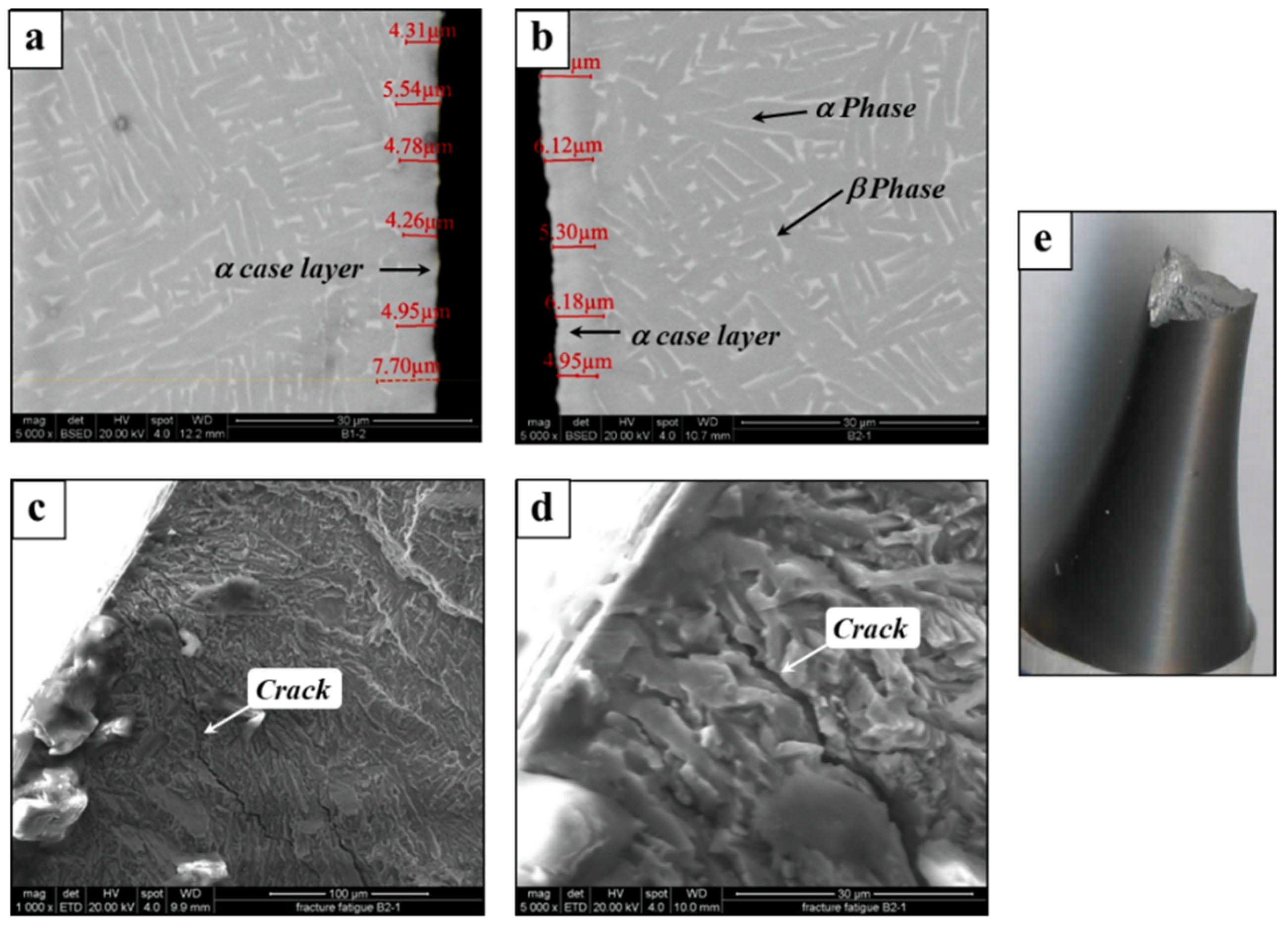
Failure in HIPed parts due to the alpha case layers can be removed by etching, which improves the fatigue limits in comparison to the as-built stress relief parts, but less than HIPed and the machined samples.
(4)
The applicable qualification standards for the examined mechanical properties correlate with conventional materials and represent the properties of AM materials; however, in many cases, they do not represent the geometry sensitivity of AM parts.

Author Contributions

O.D.: Investigation, Formal Analysis, Writing—Original Draft; T.R.: Investigation; E.A.: Investigation; A.S.: Conceptualization, Methodology, Supervision, Writing—Original Draft. All authors have read and agreed to the published version of the manuscript.

Funding

This research received no external funding.

Institutional Review Board Statement

Not applicable.

Informed Consent Statement

Not applicable.

Data Availability Statement

Experimental data from this study are available from the corresponding author upon reasonable request.

Acknowledgments

The authors thank Frage from the Department of Materials Engineering at Ben-Gurion University of the Negev for performing the HIP process in this research.

Conflicts of Interest

The authors declare no conflict of interest.

References

  1. Peters, M.; Kumpfert, J.; Ward, C.H.; Leyens, C. Titanium Alloys for Aerospace Applications. In Titanium and Titanium Alloys: Fundamentals and Applications; Leyens, C., Peters, M., Eds.; Wiley-VCH Verlag GmbH & Co. KGaA: Weinhem, Germany, 2003; Chapter 13; ISBN 9783527305346. [Google Scholar] [CrossRef]
  2. Gomez-Gallegos, A.; Mandal, P.; Gonzalez, D.; Zuelli, N.; Blackwell, P. Studies on Titanium Alloys for Aerospace Application. Defect Diffus. Forum 2018, 385, 419–423. [Google Scholar] [CrossRef] [Green Version]
  3. Henriques, V.A.R. Titanium production for aerospace applications. J. Aerosp. Technol. Manag. 2009, 1, 7–17. [Google Scholar] [CrossRef]
  4. Mirgal, N.; Ibrahim, M.M. Titanium: Metal of 21st Century. Int. J. Adv. Eng. Res. Sci. IJAERS 2016, 3, 2349–6495. Available online: www.ijaers.com (accessed on 6 June 2022).
  5. Khairallah, S.A.; Anderson, A.T.; Rubenchik, A.; King, W.E. Laser powder-bed fusion additive manufacturing: Physics of complex melt flow and formation mechanisms of pores, spatter, and denudation zones. Acta Mater. 2016, 108, 36–45. [Google Scholar] [CrossRef] [Green Version]
  6. Leon, A.; Katarivas Levy, G.; Ron, T.; Shirizly, A.; Aghion, E. The effect of strain rate on stress corrosion performance of Ti6Al4V alloy produced by additive manufacturing process. J. Mater. Res. Technol. 2020, 9, 4097–4105. [Google Scholar] [CrossRef]
  7. Negi, S.; Nambolan, A.A.; Kapil, S.; Joshi, P.S.; Raja, M.; Karunakaran, K.P.; Bhargava, P. Review on electron beam based additive manufacturing. Rapid Prototyp. J. 2020, 26, 485–498. [Google Scholar] [CrossRef]
  8. Gong, X.; Anderson, T.; Chou, K. Review on powder-based electron beam additive manufacturing technology. Manuf. Rev. 2014, 1, 2. [Google Scholar] [CrossRef]
  9. Leon, A.; Levy, G.K.; Ron, T.; Shirizly, A.; Aghion, E. The effect of hot isostatic pressure on the corrosion performance of Ti-6Al-4 V produced by an electron-beam melting additive manufacturing process. Addit. Manuf. 2020, 33, 101039. [Google Scholar] [CrossRef]
  10. Costa, L.; Vilar, R. Laser powder deposition. Rapid Prototyp. J. 2009, 15, 264–279. [Google Scholar] [CrossRef]
  11. Baghdadchi, A.; Hosseini, V.A.; Bermejo, M.A.V.; Axelsson, B.; Harati, E.; Högström, M.; Karlsson, L. Wire Laser Metal Deposition Additive Manufacturing of Duplex Stainless Steel Components—Development of a Systematic Methodology. Materials 2021, 14, 7170. [Google Scholar] [CrossRef]
  12. Ron, T.; Dolev, O.; Leon, A.; Shirizly, A.; Aghion, E. Effect of Phase Transformation on Stress Corrosion Behavior of Additively Manufactured Austenitic Stainless Steel Produced by Directed Energy Deposition. Materials 2020, 14, 55. [Google Scholar] [CrossRef] [PubMed]
  13. Ron, T.; Levy, G.K.; Dolev, O.; Leon, A.; Shirizly, A.; Aghion, E. Environmental behavior of low carbon steel produced by a wire arc additive manufacturing Process. Metals 2019, 9, 888. [Google Scholar] [CrossRef] [Green Version]
  14. Druzgalski, C.L.; Ashby, A.; Guss, G.; King, W.E.; Roehling, T.T.; Matthews, M.J. Process optimization of complex geometries using feed forward control for laser powder bed fusion additive manufacturing. Addit. Manuf. 2020, 34, 101169. [Google Scholar] [CrossRef]
  15. McNeil, J.L.; Sisco, K.; Frederick, C.; Massey, M.; Carver, K.; List, F.; Qiu, C.; Mader, M.; Sundarraj, S.; Babu, S.S. In-Situ Monitoring for Defect Identification in Nickel Alloy Complex Geometries Fabricated by L-PBF Additive Manufacturing. Metall. Mater. Trans. A 2020, 51, 6528–6545. [Google Scholar] [CrossRef]
  16. Ron, T.; Leon, A.; Popov, V.; Strokin, E.; Eliezer, D.; Shirizly, A.; Aghion, E. Synthesis of Refractory High-Entropy Alloy WTaMoNbV by Powder Bed Fusion Process Using Mixed Elemental Alloying Powder. Materials 2022, 15, 4043. [Google Scholar] [CrossRef] [PubMed]
  17. ASTM E8/E8M-09; Standard Test Methods for Tension Testing of Metallic Materials. ASTM International: West Conshohocken, PA, USA, 2012. [CrossRef]
  18. ASTM E399-17; Standard Test Method for Linear-Elastic Plane-Strain Fracture Toughness KIC of Metallic Materials. ASTM International: West Conshohocken, PA, USA, 2019. [CrossRef]
  19. ASTM E466-15; Standard Practice for Conducting Force Controlled Constant Amplitude Axial Fatigue Tests of Metallic Materials. ASTM International: West Conshohocken, PA, USA, 2021. [CrossRef]
  20. Monzón, M.D.; Ortega, Z.; Martínez, A.; Ortega, F. Standardization in additive manufacturing: Activities carried out by international organizations and projects. Int. J. Adv. Manuf. Technol. 2015, 76, 1111–1121. [Google Scholar] [CrossRef]
  21. ASTM ISO/ASTM52921-13; Standard Terminology for Additive Manufacturing-Coordinate Systems and Test Methodologies. ASTM International: West Conshohocken, PA, USA, 2019. [CrossRef]
  22. Beretta, S.; Romano, S. A comparison of fatigue strength sensitivity to defects for materials manufactured by AM or traditional processes. Int. J. Fatigue 2017, 94, 178–191. [Google Scholar] [CrossRef]
  23. Wycisk, E.; Solbach, A.; Siddique, S.; Herzog, D.; Walther, F.; Emmelmann, C. Effects of Defects in Laser Additive Manufactured Ti-6Al-4V on Fatigue Properties. Phys. Procedia 2014, 56, 371–378. [Google Scholar] [CrossRef] [Green Version]
  24. Ganor, Y.I.; Tiferet, E.; Vogel, S.C.; Brown, D.W.; Chonin, M.; Pesach, A.; Hajaj, A.; Garkun, A.; Samuha, S.; Shneck, R.Z.; et al. Tailoring Microstructure and Mechanical Properties of Additively-Manufactured Ti6Al4V Using Post Processing. Materials 2021, 14, 658. [Google Scholar] [CrossRef]
  25. Tiferet, E.; Ganor, M.; Zolotaryov, D.; Garkun, A.; Hadjadj, A.; Chonin, M.; Ganor, Y.; Noiman, D.; Halevy, I.; Tevet, O.; et al. Mapping the Tray of Electron Beam Melting of Ti-6Al-4V: Properties and Microstructure. Materials 2019, 12, 1470. [Google Scholar] [CrossRef] [Green Version]
  26. ASTM F2924-14; Standard Specification for Additive Manufacturing Titanium-6 Aluminum-4 Vanadium with Powder Bed Fusion. ASTM International: West Conshohocken, PA, USA, 2014.
  27. Quintus Technologies AB; Oak Ridge National Laboratory. Hot Isostatic Pressing: Improving quality and performance in AM parts Production. Metal Addit. Manuf. 2015, 1, 41–50. [Google Scholar]
  28. Leuders, S.; Tröster, T.; Riemer, A.; Richard, H.A.; Niendorf, T. On the mechanical performance of structures manufactured by selective laser melting: Damage initiation and propagation. In Proceedings of the Additive Manufacturing with Powder Metallurgy Conference, Orlando, FL, USA, 18–20 May 2014. [Google Scholar]
  29. Günther, J.; Krewerth, D.; Lippmann, T.; Leuders, S.; Tröster, T.; Weidner, A.; Biermann, H.; Niendorf, T. Fatigue life of additively manufactured Ti–6Al–4V in the very high cycle fatigue regime. Int. J. Fatigue 2017, 94, 236–245. [Google Scholar] [CrossRef]
  30. Sanaei, N.; Fatemi, A. Defects in additive manufactured metals and their effect on fatigue performance: A state-of-the-art review. Prog. Mater. Sci. 2021, 117, 100724. [Google Scholar] [CrossRef]
  31. Horiya, T.; Kishi, T. Fracture Toughness of Titanium Alloys; Nippon Steel Report No. 62; UDC620.178.2:699.295; Nippon Steel: Tokyo, Japan, July 1994. [Google Scholar]
  32. Dhansay, N.M.; Tait, R.; Becker, T. Fatigue and Fracture Toughness of Ti-6Al-4V Titanium Alloy Manufactured by Selective Laser Melting. Adv. Mater. Res. 2014, 1019, 248–253. [Google Scholar] [CrossRef]
  33. Hooreweder, B.V.; Moens, D.; Boonen, R.; Kruth, J.-P.; Sas, P. Analysis of Fracture Toughness and Crack Propagation of Ti-6Al-4V produced by Selective Laser Melting. Adv. Eng. Mater. 2012, 14, 92–97. [Google Scholar] [CrossRef]
  34. Hartunian, P.; Eshraghi, M. Effect of Build Orientation on the Microstructure and Mechanical Properties of Selective Laser-Melted Ti-6Al-4V. Alloy J. Manuf. Mater. Process. 2018, 2, 69. [Google Scholar] [CrossRef] [Green Version]
  35. Becker, T.H.; Beck, M.; Scheffer, C. Microstacture and Mechanical Properties of Direct Metal Laser Sintered TI-6AL-4V. Propagation of Ti6Al4V Produced by Selective Laser Melting. S. Afr. J. Ind. 2015, 26, 1–10. [Google Scholar] [CrossRef] [Green Version]
  36. Williams, J.; Boyer, R.R. Opportunities and Issues in the Application of Titanium Alloys for Aerospace Components. Metals 2020, 10, 705. [Google Scholar] [CrossRef]
  37. Aguilar-Duque, J.I.; García-Alcaraz, J.L.; Hernández-Arellano, J.L. Geometric considerations for the 3D printing of components using fused filament fabrication. Int. J. Adv. Manuf. Technol. 2020, 109, 171–186. [Google Scholar] [CrossRef]
  38. Masuo, H.; Tanaka, Y.; Morokoshi, S.; Yagura, H.; Uchida, T.; Yamamoto, Y.; Murakami, Y. Influence of defects, surface roughness and HIP on the fatigue strength of Ti-6Al-4V manufactured by additive manufacturing. Int. J. Fatigue 2018, 117, 163–179. [Google Scholar] [CrossRef]
  39. Kasperovich, G.; Hausmann, J. Improvement of fatigue resistance and ductility of TiAl6V4 processed by selective laser melting. J. Mater. Process. Technol. 2015, 220, 202–214. [Google Scholar] [CrossRef]
  40. Dzugan, J.; Seifi, M.; Prochazka, R.; Rund, M.; Podany, P.; Konopik, P.; Lewandowski, J.J. Effects of thickness and orientation on the small scale fracture behavior of additively manufactured Ti-6Al-4V. Mater. Charact. 2018, 143, 94–109. [Google Scholar] [CrossRef]
  41. Greitemeier, D.; Dalle Donne, C.; Syassen, F.; Eufinger, J.; Melz, T. Effect of surface roughness on fatigue performance of additive manufactured Ti–6Al–4V. Mater. Sci. Technol. 2016, 32, 629–634. [Google Scholar] [CrossRef]
  42. Sanaeia, N.; Fatemi, A. Analysis of the effect of surface roughness on fatigue performance of powder bed fusion additive manufactured metals. Theor. Appl. Fract. Mech. 2020, 108, 102638. [Google Scholar] [CrossRef]
  43. Li, S.; Zhang, B.; Bai, Q. Effect of temperature buildup on milling forces in additive/subtractive hybrid manufacturing of Ti-6Al-4V. Int. J. Adv. Manuf. Technol. 2020, 107, 4191–4200. [Google Scholar] [CrossRef]
  44. Prado-Cerqueira, J.; Diéguez, J.L.; Camacho, A.M. Preliminary development of a Wire and Arc Additive Manufacturing system (WAAM). Procedia Eng. 2017, 13, 895–902. [Google Scholar] [CrossRef]
  45. Seth, P.; Jha, J.S.; Alankar, A.; Mishra, S.K. Alpha-case Formation in Ti–6Al–4V in a Different Oxidizing Environment and Its Effect on Tensile and Fatigue Crack Growth Behavior. Oxid. Met. 2022, 97, 77–95. [Google Scholar] [CrossRef]
Figure 1. Geometries and dimensions of samples: (a) tensile samples (ASTM E8), (b) Compact-Tension (CT25) specimen (ASTM E399-17), (c) fatigue samples (ASTM E466).
Metals 12 01210 g001
Figure 2. The HIPed temperature and pressure over time.
Metals 12 01210 g002
Figure 3. Schematic illustration of the post-process sample preparations.
Metals 12 01210 g003
Figure 4. Typical fracture of CT25 sample according to ASTM E399 Standard.
Metals 12 01210 g004
Figure 5. Fatigue behavior of DMLS TiAl6V4 alloy in a high cycle—as-built and machined samples.
Metals 12 01210 g005
Figure 6. Fatigue behavior of DMLS TiAl6V4 alloy with various preparation methods.
Metals 12 01210 g006
Figure 7. Fracture and microstructure of HIPed and machined sample: (a,b) typical microstructures of TiAl6V4 after HIP treatment, (c,d) fractography analysis of TiAl6V4 alloy after fatigue failure, (e) TiAl6V4 sample after failure.
Metals 12 01210 g007
Figure 8. Machined and HIPed specimens (with alpha case) (a) prior to etching, (b) after etching.
Metals 12 01210 g008
Table 1. The chemical composition of the Ti-6Al-4V powder used for samples preparation.
Composition [%]AlVFeOCNHYTi
LPW powder6.383.980.180.090.0140.0140.0011<0.0003Bal.
ASTM F2924 requirement [24]5.50–6.753.50–4.50Up to 0.30Up to 0.20Up to 0.08Up to 0.05Up to 0.015Up to 0.005Bal.
Table 2. Tensile test results of as-built stress relief and HIPed samples.
Elastic Modulus [MPa]Yield Stress
[MPa]
Ultimate Stress
[MPa]
Elongation
[%]
Reduction of Area [%]
As-built stress relief111,665 ± 39711092.9 ± 7.61174.1 ± 6.18.7 ± 0.329 ± 1.4
As-built stress relief and HIP109,000 ± 4242855.9 ± 5.7949.3 ± 1015.3 ± 0.642.8 ± 2.6
Requirement (ASTM)113,8008609208
Table 3. Fracture toughness KIC of as-built stress relief and the HIPed samples.
Specimen Average   Crack   Size   [ mm ] Fracture   Load   [ KN ] KIC
[ MPa m ]
As-built stress relief116.925.9553.42 a
215.978.1345.65
314.227.1641.60 b
413.508.1943.21
513.678.2844.66
Average44.5
As-built stress relief and HIP112.2118.3683.60
213.0516.3582.51
313.6715.7686.18 b
414.02 a14.9785.80
513.4616.0085.06
Average84.6
Requirement (ASTM)Annealed plate75
Requirement (ASTM)STA plate42.9
a—The overall crack length (starter notch and fatigue crack) during the pre-crack operation exceeds the recommended value (0.55 W max). b—The central flat fracture area was not parallel to the starter notch plane.
Publisher’s Note: MDPI stays neutral with regard to jurisdictional claims in published maps and institutional affiliations.

