
Effect of Q235 Hot-Dip Galvanized and Post-Casting T6 Heat Treatment on Microstructure and Mechanical Properties of Interfacial between AZ63 and Q235 by Solid-Liquid Compound Casting

Abstract
:1. Introduction
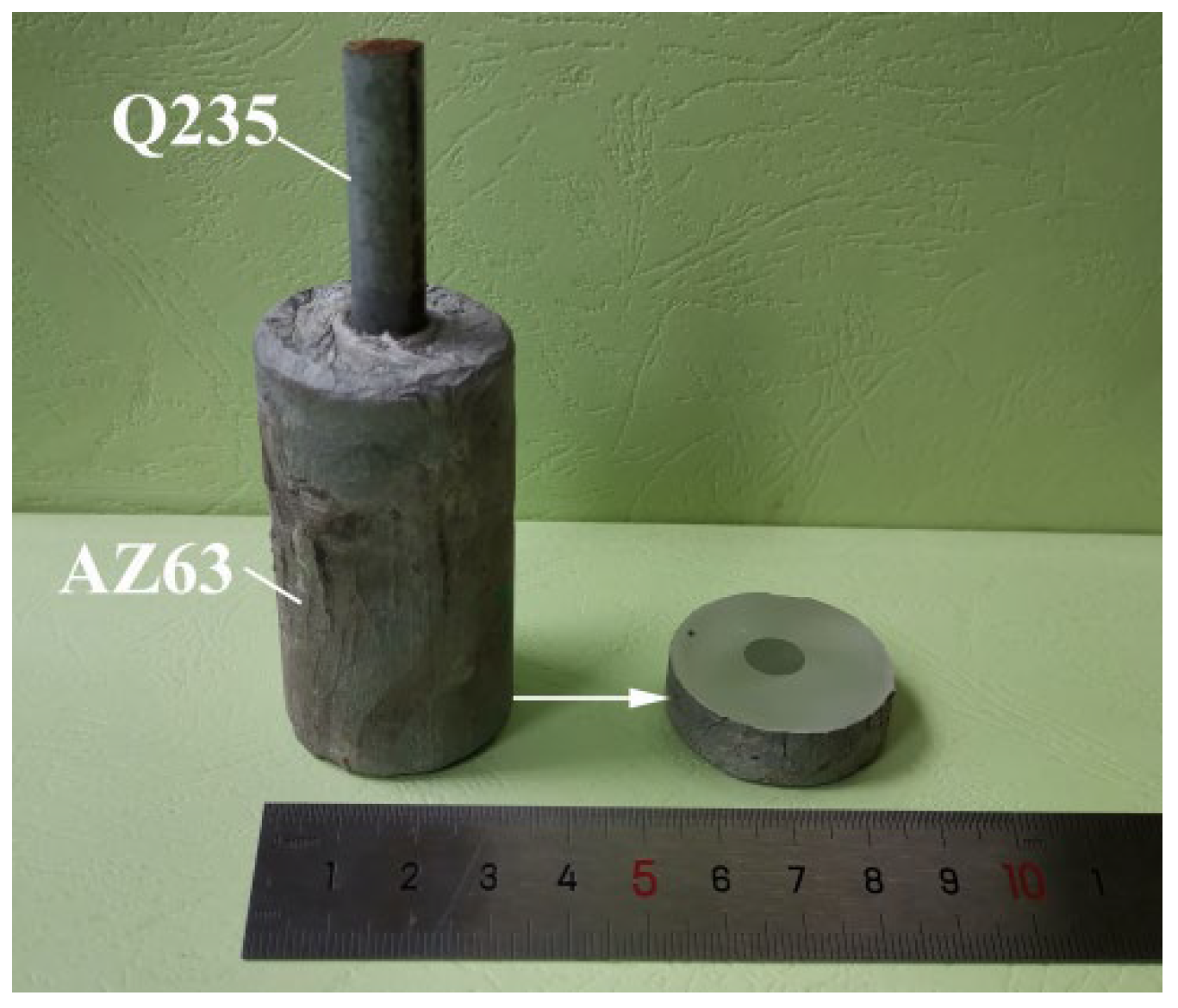
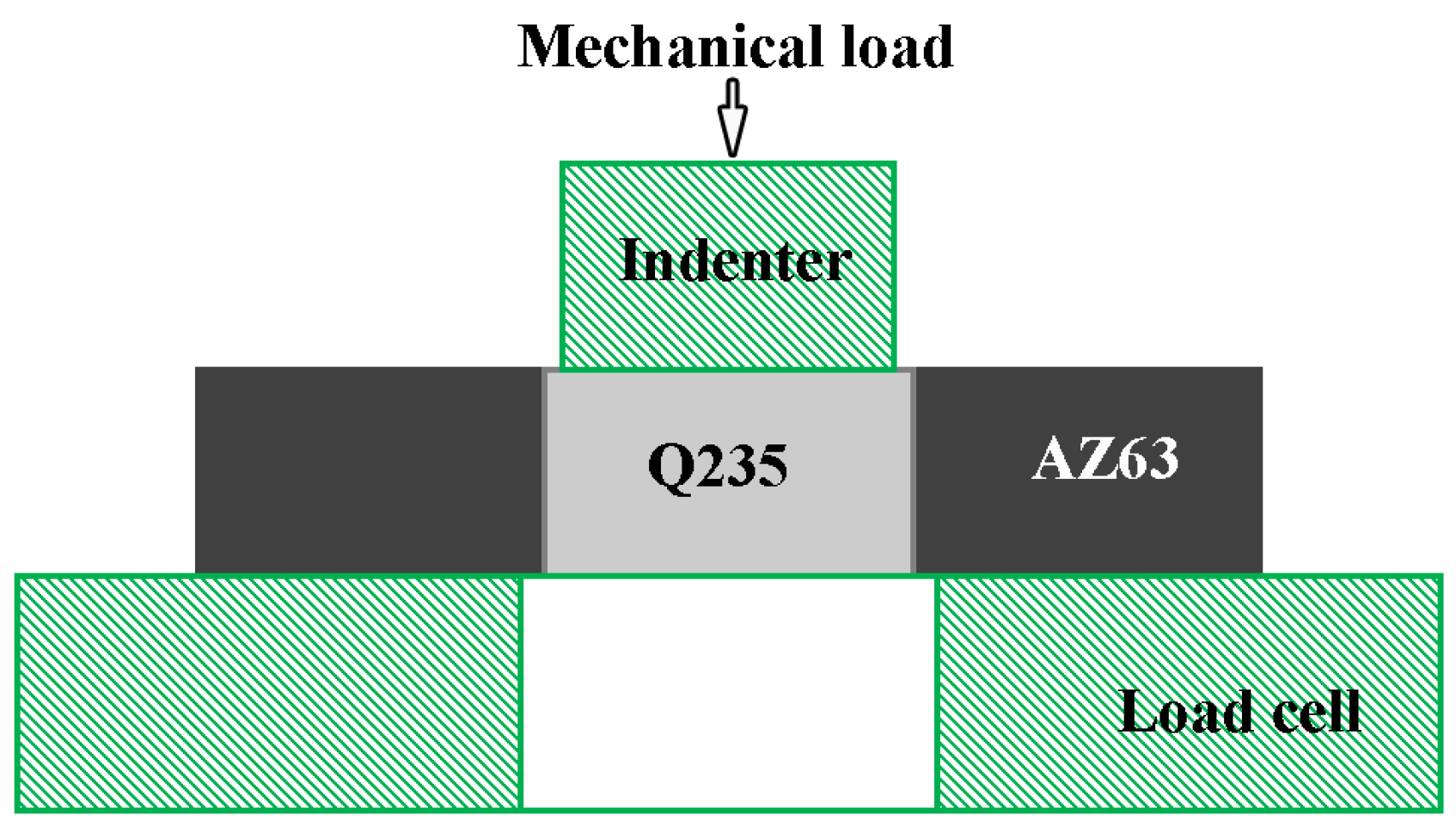
2. Experimental
3. Results and Discussion
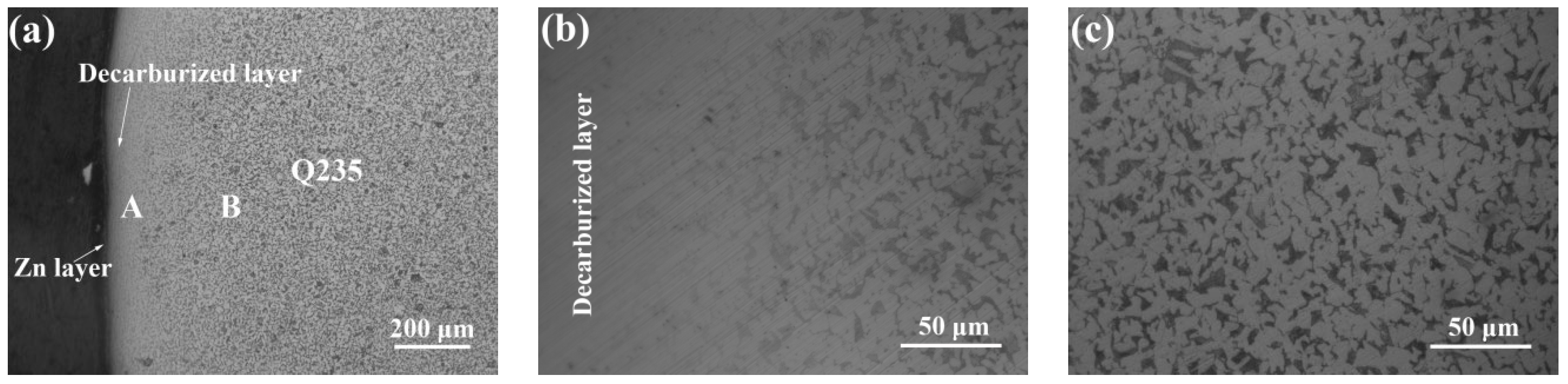
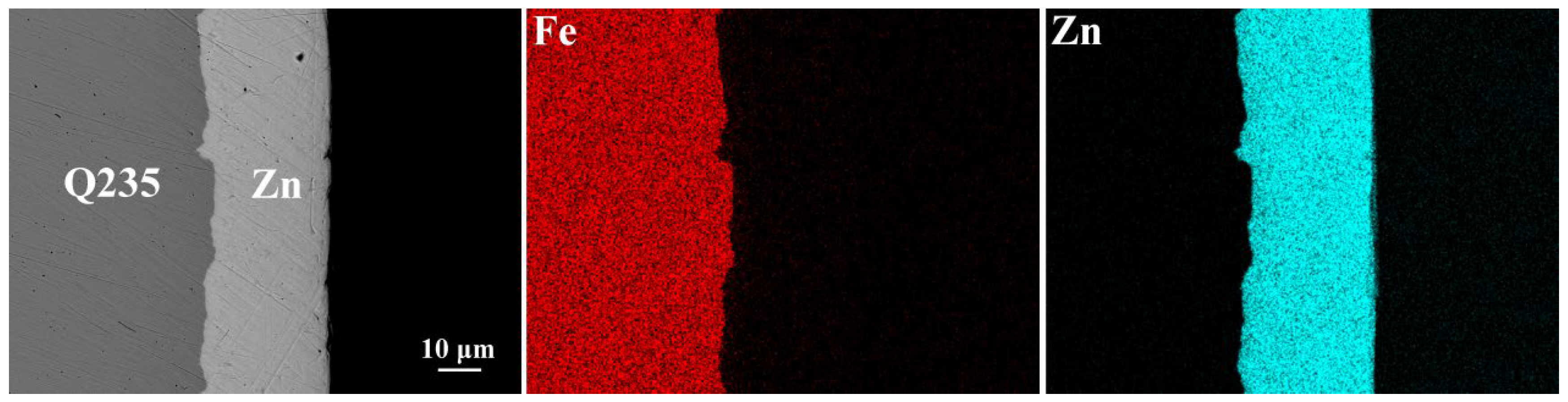
3.1. Galvanized Q235 Microstructure
3.2. Microstructure of the Interfaces between AZ63 and Q235 Bimetallic Composites
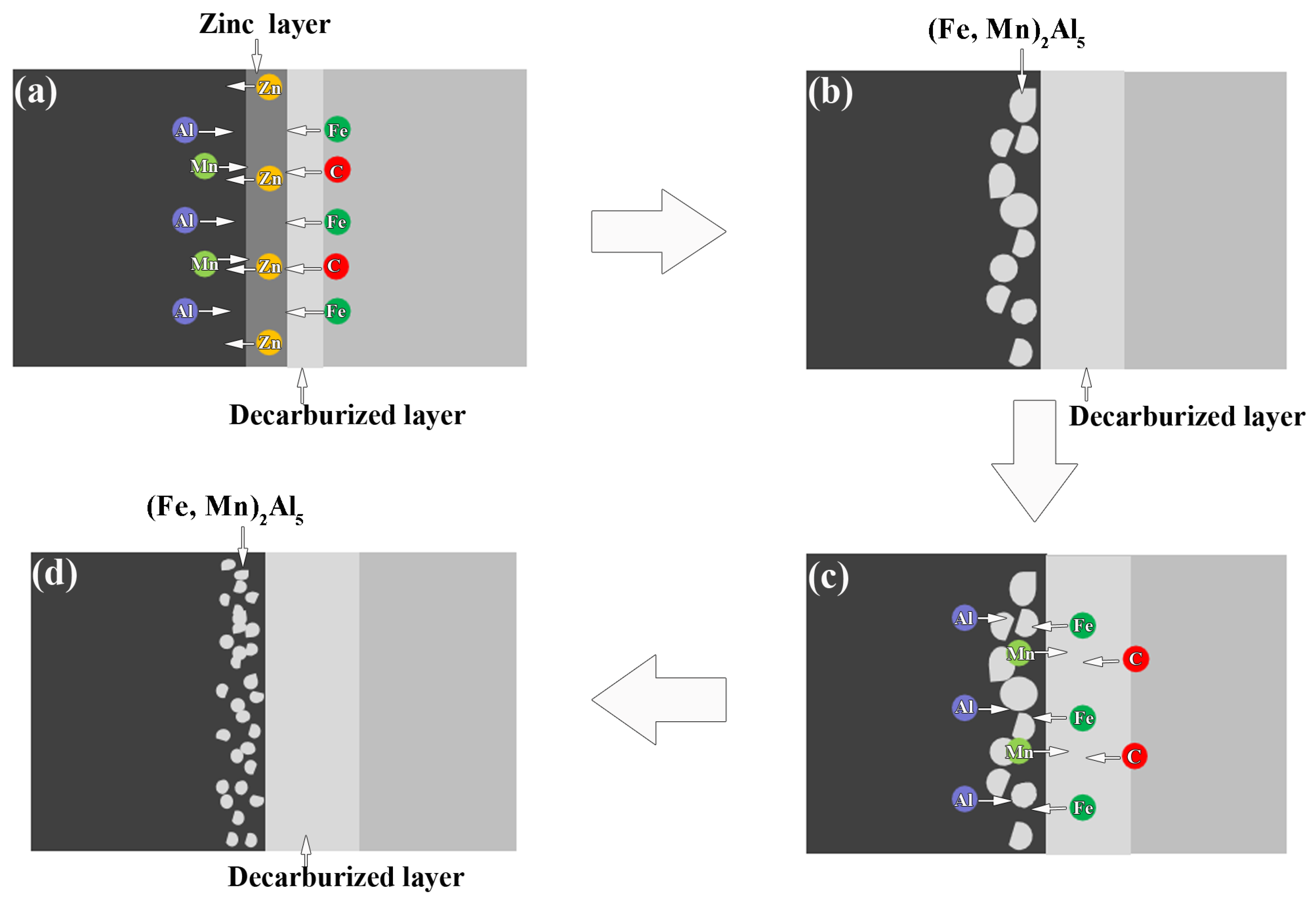
3.3. Reaction Mechanism of AZ63 and Q235 Interfaces
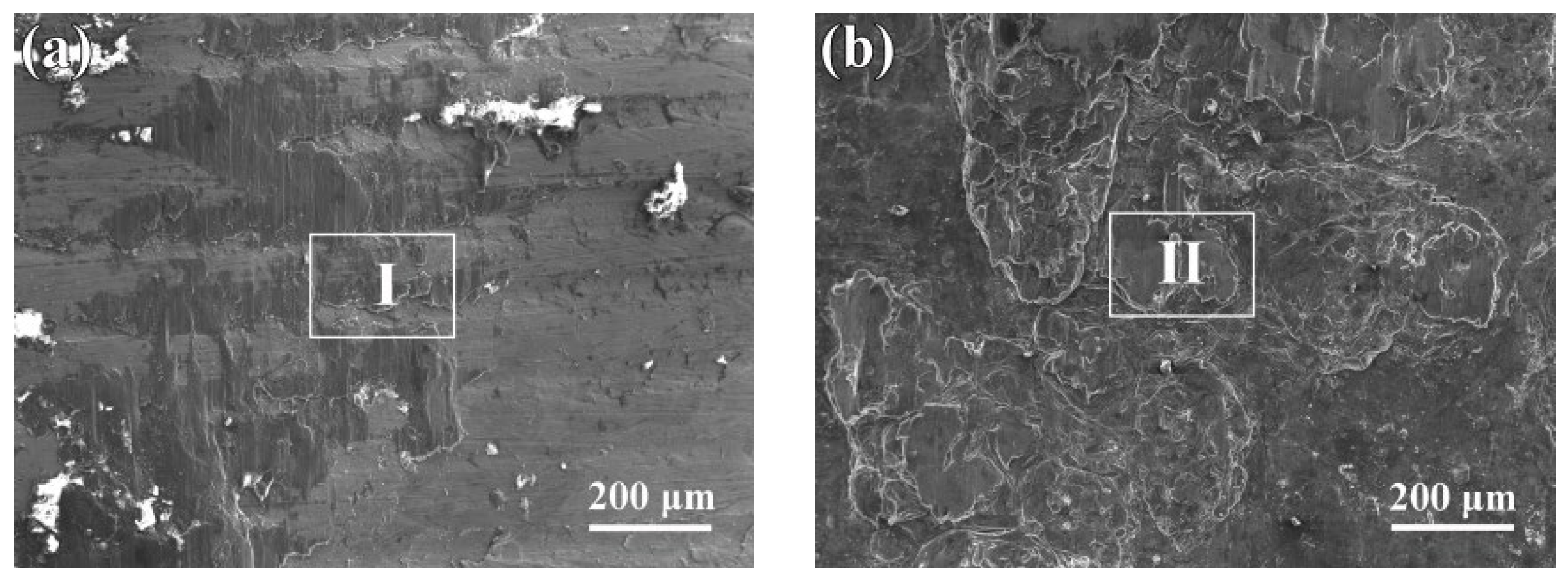
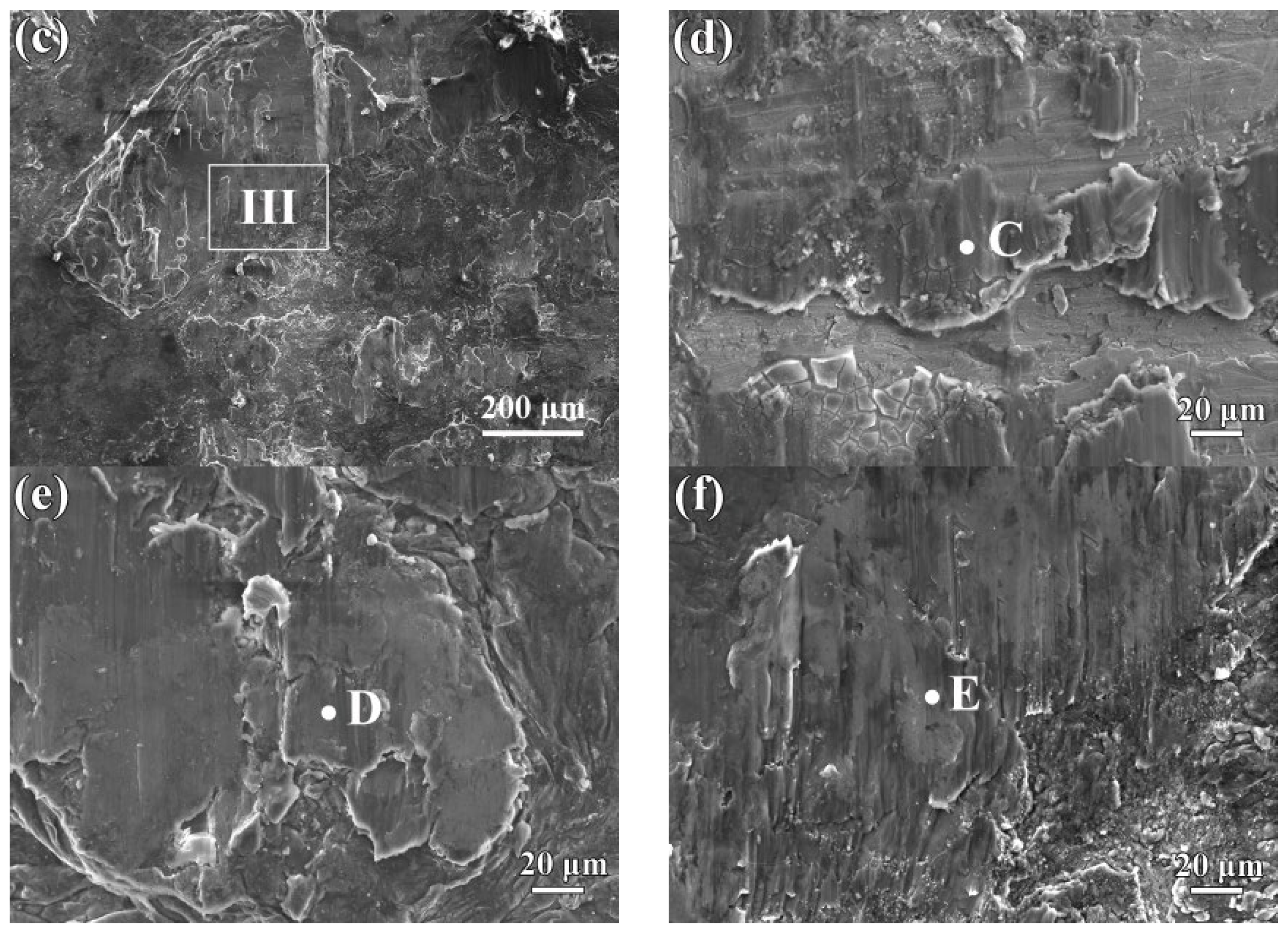
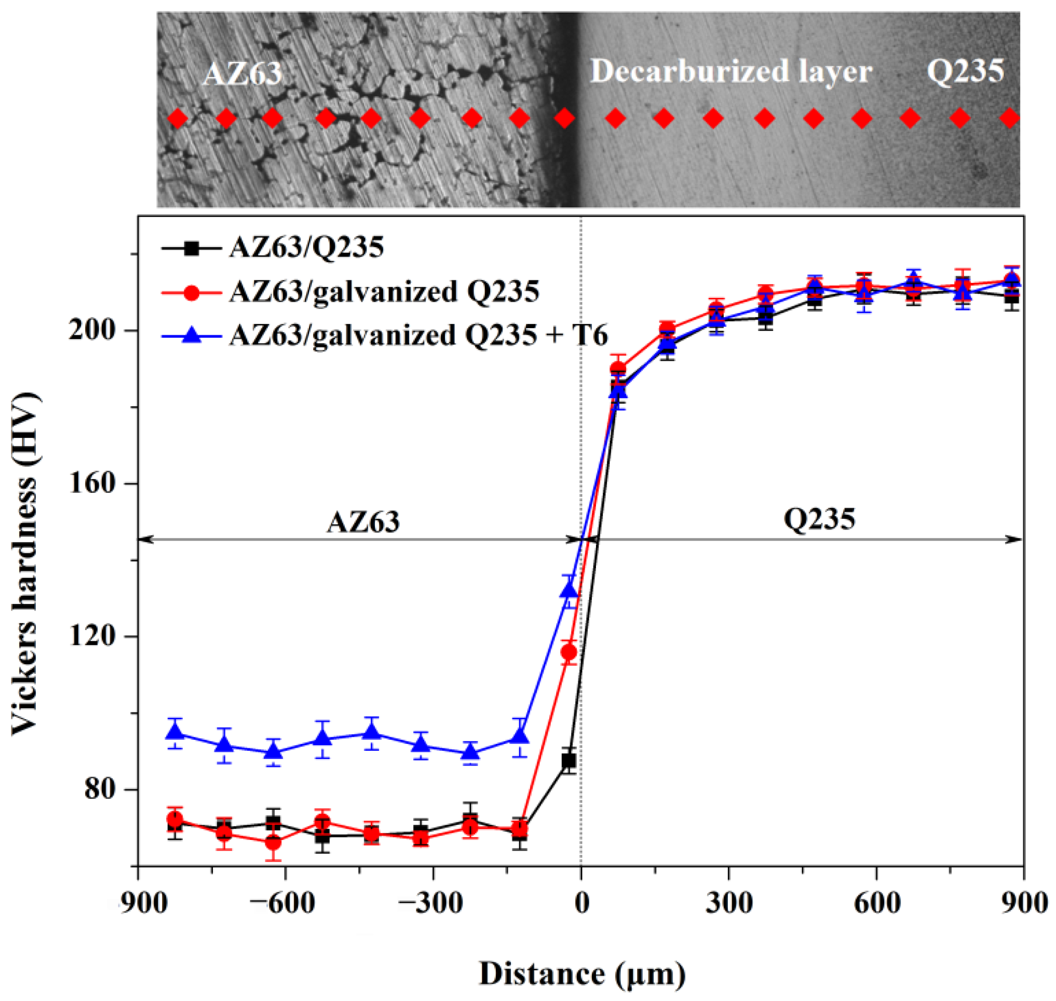
3.4. Mechanical Properties
4. Conclusions
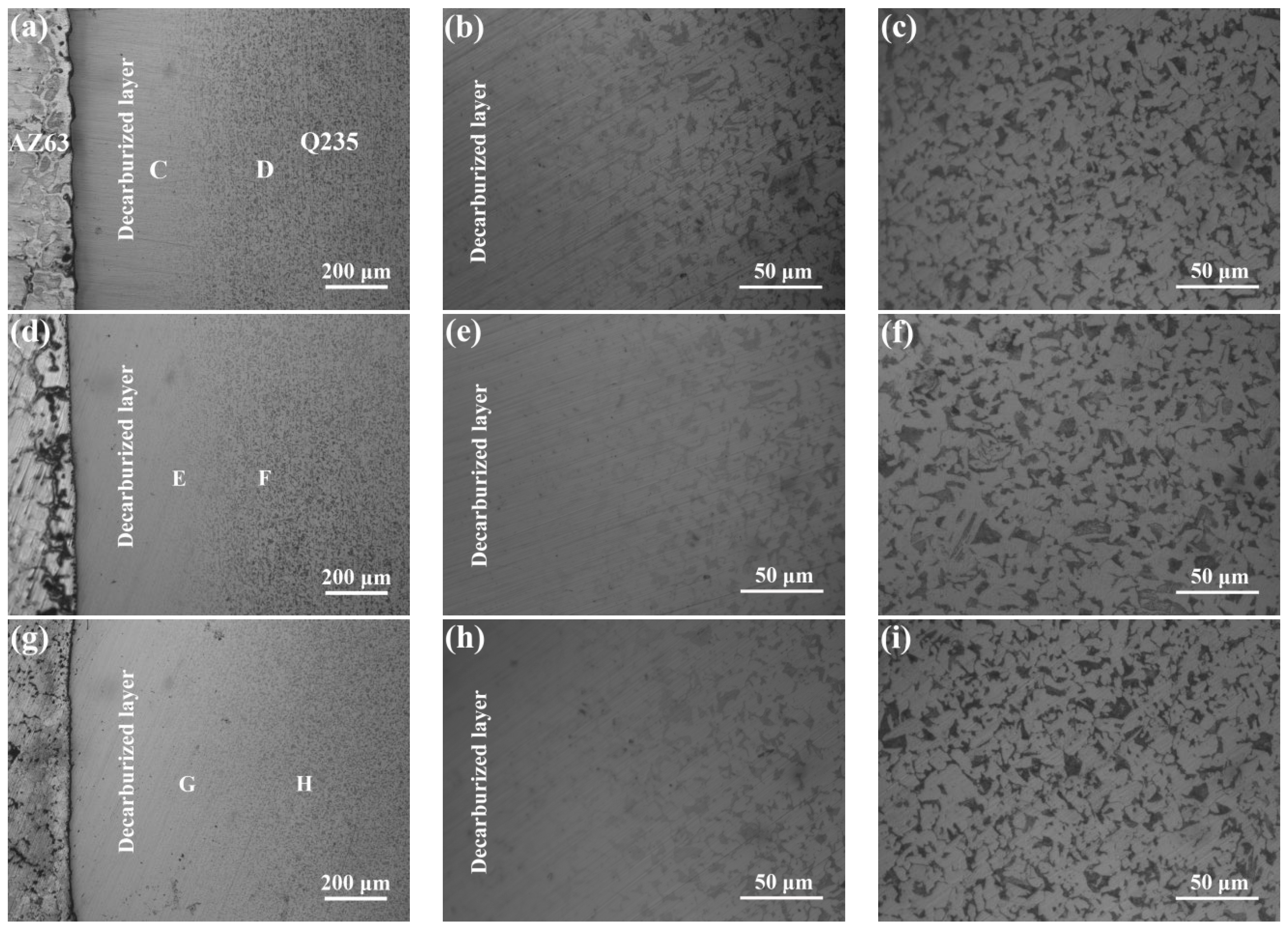
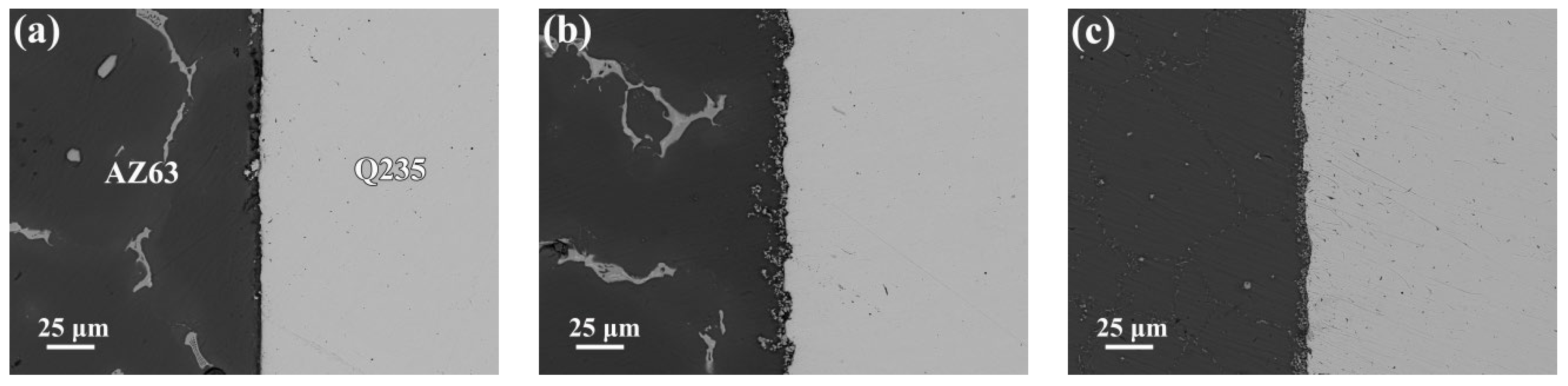
- The Q235 matrix of the AZ63/Q235, AZ63/galvanized Q235, and AZ63/galvanized Q235 + T6 treated samples formed a decarburized layer with a thickness of 300–350 μm near the interface. A small amount of intermetallic compounds was formed at the interface of AZ63/Q235, and a transition layer with an average thickness of about 15 μm was formed at the interface of AZ63/galvanized Q235. After T6 treatment, the average thickness of the interface transition layer between AZ63 and galvanized Q235 base layer was still about 15 μm, but the thickness of the transition layer became more uniform, and the size of the intermetallic compound was obviously refined.
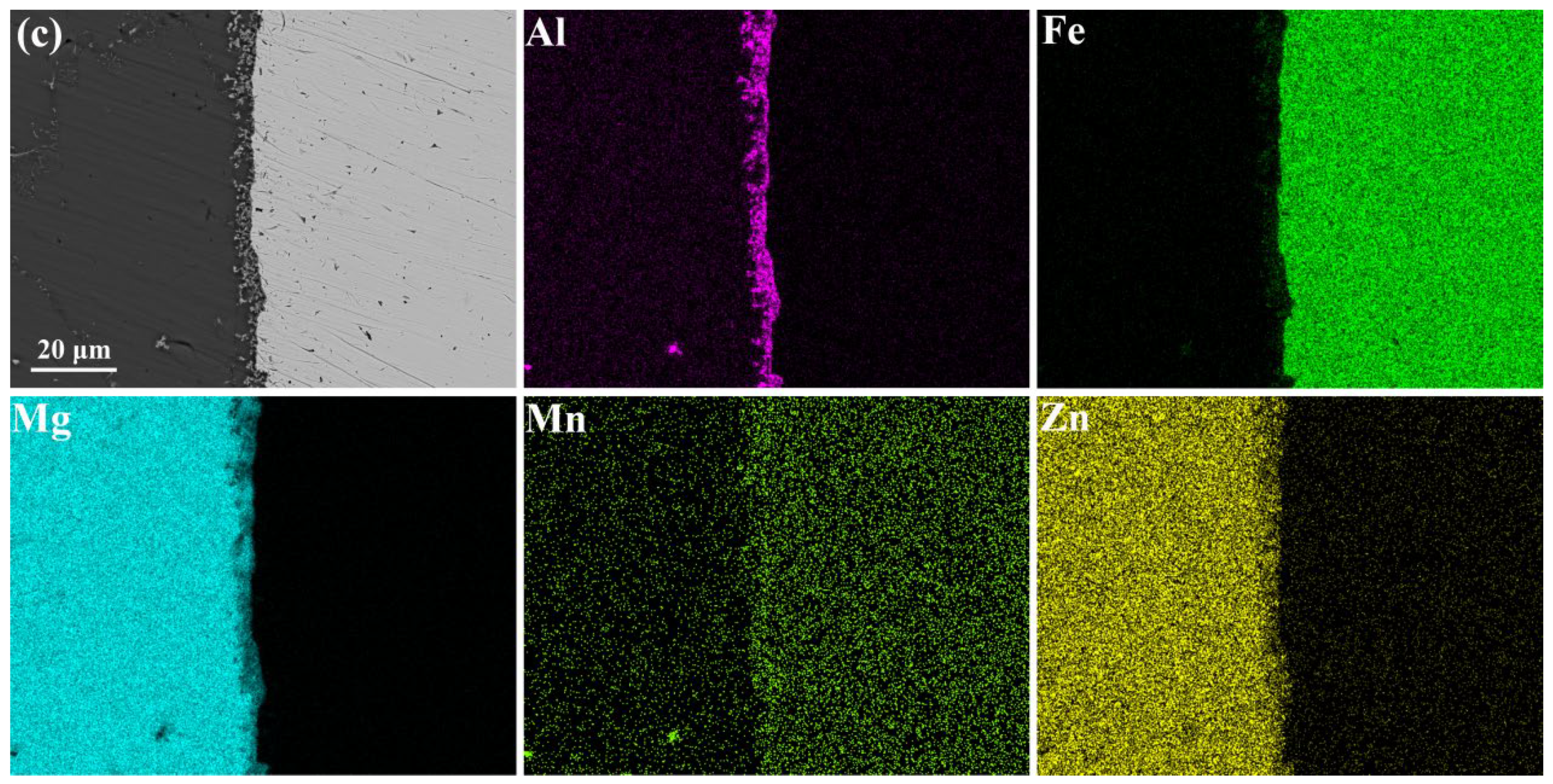
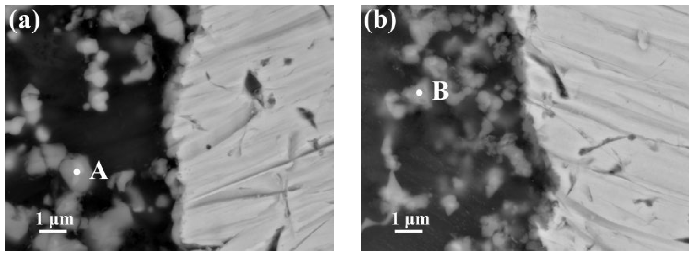
- The Al Mn, and Fe elements were obviously aggregated at the interface of AZ63/galvanized Q235. However, the zinc on the surface of the galvanized Q235 melted into the AZ63 magnesium alloy during the casting. After T6 treatment, the Al, Mn, and Zn elements in the matrixes were uniformly distributed, but the Al element at the interface was obviously increased, while the Mn element was obviously decreased. The intermetallic compound at the interfaces of AZ63/galvanized Q235 was (Fe, Mn)2Al5 before and after T6 treatment.
- The shear strength of AZ63/Q235, AZ63/galvanized Q235, and AZ63/galvanized Q235 + T6 metallurgical bonding presents an increasing tendency. The hardness of the interface near the AZ63 matrix was significantly higher than that of the AZ63 matrix, and the interface of the AZ63/galvanized Q235 + T6 has the highest hardness, while the hardness of the AZ63/Q235 is the lowest.
Author Contributions
Funding
Institutional Review Board Statement
Informed Consent Statement
Data Availability Statement
Conflicts of Interest
References
- Parthiban, G.T.; Parthiban, T.; Ravi, R.; Saraswathy, V.; Palaniswamy, N.; Sivanb, V. Cathodic protection of steel in concrete using magnesium alloy anode. Corros. Sci. 2008, 50, 3329–3335. [Google Scholar] [CrossRef]
- Kim, J.G.; Joo, J.H.; Koo, S.J. Development of high-driving potential and high-efficiency Mg-based sacrificial anodes for cathodic protection. J. Mater. Sci. Lett. 2000, 19, 477–479. [Google Scholar] [CrossRef]
- Pathak, S.S.; Mendon, S.K.; Blanton, M.D.; Rawlins, J.W. Magnesium-based sacrificial anode cathodic protection coatings (Mg-rich primers) for aluminum alloys. Metals 2012, 2, 353–376. [Google Scholar] [CrossRef]
- Yan, L.; Song, G.L.; Zheng, D. Magnesium alloy anode as a smart corrosivity detector and intelligent sacrificial anode protector for reinforced concrete. Corros. Sci. 2019, 155, 13–28. [Google Scholar] [CrossRef]
- Li, J.; Chen, Z.; Jing, J.; Hou, J. Effect of yttrium modification on the corrosion behavior of AZ63 magnesium alloy in sodium chloride solution. J. Magnes. Alloy. 2021, 9, 613–626. [Google Scholar] [CrossRef]
- Jafari, H.; Mohammad Hassanizadeh, B. Influence of Zr and Be on microstructure and electrochemical behavior of AZ63 anode. Mater. Corros. 2019, 70, 633–641. [Google Scholar] [CrossRef]
- Kim, J.G.; Koo, S.J. Effect of alloying elements on electrochemical properties of magnesium-based sacrificial anodes. Corrosion 2000, 56, 380–388. [Google Scholar] [CrossRef]
- Liu, L.; Qi, X.; Wu, Z. Microstructural characteristics of lap joint between magnesium alloy and mild steel with and without the addition of Sn element. Mater. Lett. 2010, 64, 89–92. [Google Scholar] [CrossRef]
- Nayeb-Hashemi, A.A.; Clark, J.B.; Swartzendruber, L.J. The Fe-Mg (Iron-Magnesium) system. Bull. Alloy. Phase Diagr. 1985, 6, 235–238. [Google Scholar] [CrossRef]
- Patel, V.K.; Bhole, S.D.; Chen, D.L. Formation of zinc interlayer texture during dissimilar ultrasonic spot welding of magnesium and high strength low alloy steel. Mater. Des. 2013, 45, 236–240. [Google Scholar] [CrossRef]
- Sacerdote-Peronnet, M.; Guiot, E.; Bosselet, F.; Dezellus, O.; Rouby, D.; Viala, J.C. Local reinforcement of magnesium base castings with mild steel inserts. Mat. Sci. Eng. A 2007, 445, 296–301. [Google Scholar] [CrossRef]
- Cheng, J.; Zhao, J.; Zhang, J.; Guo, Y.; He, K.; Shang-Guan, J.; Wen, F. Microstructure and mechanical properties of galvanized-45 steel/AZ91D bimetallic material by liquid-solid compound casting. Materials 2019, 12, 1651. [Google Scholar] [CrossRef] [Green Version]
- Cheng, J.; Zhao, J.; Zheng, D.; He, K.; Guo, Y. Effect of the vacuum heat treatment on the microstructure and mechanical properties of the galvanized-Q235/AZ91D bimetal material produced by solid-liquid compound casting. Met. Mater. Int. 2021, 27, 545–555. [Google Scholar] [CrossRef]
- Jiang, W.; Jiang, H.; Li, G.; Guan, F.; Zhu, J.; Fan, Z. Microstructure, mechanical properties and fracture behavior of magnesium/steel bimetal using compound casting assisted with hot-dip aluminizing. Met. Mater. Int. 2021, 27, 2977–2988. [Google Scholar] [CrossRef]
- Zhao, J.; Zhao, W.; Shen, Q.U.; Zhang, Y.Q. Microstructures and mechanical properties of AZ91D/0Cr19Ni9 bimetal composite prepared by liquid-solid compound casting. Trans. Nonferrous Met. Soc. China 2019, 29, 51–58. [Google Scholar] [CrossRef]
- Kartsonakis, I.A.; Stanciu, S.G.; Matei, A.A.; Hristu, R.; Karantonis, A.; Charitidis, C.A. A comparative study of corrosion inhibitors on hot-dip galvanized steel. Corros. Sci. 2016, 112, 289–307. [Google Scholar] [CrossRef]
- Chen, Y.C.; Nakata, K. Friction stir lap welding of magnesium alloy and zinc-coated steel. Mater. Trans. 2009, 50, 2598–2603. [Google Scholar] [CrossRef] [Green Version]
- Jafari, H.; Idris, M.H.; Ourdjini, A.; Payganeh, G. Effect of thermomechanical treatment on microstructure and hardness behavior of AZ63 magnesium alloy. Acta Metall. Sin. 2009, 22, 401–407. [Google Scholar] [CrossRef] [Green Version]
- Takeuchi, A.; Inoue, A. Classification of bulk metallic glasses by atomic size difference, heat of mixing and period of constituent elements and its application to characterization of the main alloying element. Mater. Trans. 2005, 46, 2817–2829. [Google Scholar] [CrossRef] [Green Version]
- Li, X.; Scherf, A.; Heilmaier, M.; Stein, F. The Al-rich part of the Fe-Al phase diagram. J. Phase. Equilib. Diff. 2016, 37, 162–173. [Google Scholar] [CrossRef] [Green Version]
- Shi, Y.; He, C.C.; Huang, J.K.; Fan, D. Thermodnamic Analysis of the Forming of Intermetallic Compounds on Aluminium-Steel Welding Interface. J. Lanzhou Univ. Technol. 2013, 39, 45–47. [Google Scholar]


| Materials | Al | Zn | Ni | Cu | Mn | Si | Mg | C | S | P | Fe |
|---|---|---|---|---|---|---|---|---|---|---|---|
| AZ63 | 5.7 | 3.1 | 0.001 | 0.002 | 0.51 | 0.08 | Bal. | - | - | - | 0.004 |
| Q235 | - | - | - | - | 0.5 | 0.3 | - | 0.12 | 0.04 | 0.0035 | Bal. |
| A–B | Al–Fe | Al–Mg | Al–Mn | Al–Zn | Fe–Mn | Fe–Zn | Mg–Mn | Mg–Zn | Mn–Zn |
|---|---|---|---|---|---|---|---|---|---|
| (kJ/mol) | −11 | −2 | −10 | 1 | 0 | 4 | 10 | −4 | −6 |
| Point | C | Fe | Al | Mn | Mg | Zn | Fe/Al |
|---|---|---|---|---|---|---|---|
| A | 4.417 | 20.374 | 48.802 | 16.821 | 9.439 | 0.146 | 0.41 |
| B | 6.347 | 16.66 | 41.766 | 3.961 | 30.633 | 0.633 | 0.40 |
| Sample | Average Shear Strength (MPa) |
|---|---|
| AZ63/Q235 | 8.2 ± 0.4 |
| AZ63/galvanized Q235 | 21.3 ± 0.5 |
| AZ63/galvanized Q235 + T6 | 31.9 ± 1.9 |
| Point | Mg | Al | Zn | Mn |
|---|---|---|---|---|
| C | 94.2 | 4.9 | 0.7 | 0.2 |
| D | 94.4 | 2.6 | 2.6 | 0.4 |
| E | 96.2 | 2.6 | 1.1 | 0.1 |
Publisher’s Note: MDPI stays neutral with regard to jurisdictional claims in published maps and institutional affiliations. |
© 2022 by the authors. Licensee MDPI, Basel, Switzerland. This article is an open access article distributed under the terms and conditions of the Creative Commons Attribution (CC BY) license (https://creativecommons.org/licenses/by/4.0/).
Share and Cite
Dai, J.; Xie, H.; Zhou, Y.; Zou, Q.; Tian, Y.; Yang, Q.; Peng, C.; Jiang, B.; Zhang, J. Effect of Q235 Hot-Dip Galvanized and Post-Casting T6 Heat Treatment on Microstructure and Mechanical Properties of Interfacial between AZ63 and Q235 by Solid-Liquid Compound Casting. Metals 2022, 12, 1233. https://doi.org/10.3390/met12071233
Dai J, Xie H, Zhou Y, Zou Q, Tian Y, Yang Q, Peng C, Jiang B, Zhang J. Effect of Q235 Hot-Dip Galvanized and Post-Casting T6 Heat Treatment on Microstructure and Mechanical Properties of Interfacial between AZ63 and Q235 by Solid-Liquid Compound Casting. Metals. 2022; 12(7):1233. https://doi.org/10.3390/met12071233
Chicago/Turabian StyleDai, Jiahong, Hongmei Xie, Yangyang Zhou, Qin Zou, Yuan Tian, Qingshan Yang, Cheng Peng, Bin Jiang, and Jianyue Zhang. 2022. "Effect of Q235 Hot-Dip Galvanized and Post-Casting T6 Heat Treatment on Microstructure and Mechanical Properties of Interfacial between AZ63 and Q235 by Solid-Liquid Compound Casting" Metals 12, no. 7: 1233. https://doi.org/10.3390/met12071233