Abstract
In this study, steel/aluminum bimetal gears were manufactured under different deformation degrees by using hot forging processing. Optical microscope (OM), scanning electron microscopy (SEM) and energy disperse spectroscopy (EDS) were used to observe morphologies and the element composition of the interface region of the bimetal gears with different deformation degrees. Results show that the interface region between steel and aluminum is of mechanical bonding characteristics when the deformation degree is 50% and 70%, and the steel–aluminum interface joining zone is of the metallurgical bonding feature when the deformation degree is 90%. Finite element (FE) simulation of the hot forging process of the bimetal gear was carried out by using DEFORM-3D software. The simulation results show that the increase in the difference between the interfacial radial stress and the flow stress of the steel helps to form metallurgical bonding at the steel–aluminum joining zone.
1. Introduction
Nowadays, some scholars focused their research on extending the present forming technology from a single material to a multi-material to reduce resource and energy consumption [1], and also to meet the different demands of the load [2]. Spur gears are widely used in the field of mechanical engineering as an important transmission part, and require good wear resistance of the tooth flank in service.
At present, gears are manufactured using mono-material with the conventional mechanical cutting method, and a narrow web or drilled hole in them are used to reduce the weight of the gear to save fuel and reduce emissions. So it is a new research trend to develop multi-material forming technology to lower the total weight and improve mechanical property on functional surfaces at the same time. Politis et al. [3] analyzed the material flow and thickness distribution of the copper-lead bimetal gears using the forging technique by combining numerical simulation and process experiments. Wu et al. [4] studied the material flow behavior and the effect of the gap and the height difference between the steel ring and the aluminum core on the forming process during the precision forging of steel–aluminum bimetal gear. Chavdar et al. [5] manufactured the gears by hot-hydraulic forging of steel and aluminum bimetallic billets to achieve the lightweight of gears. Yılmaz et al. [6] evaluated the static and dynamic behavior of bimetallic spur gears with different gear parameters by finite element analysis; the results indicate that bimetallic gears have a great potential in reducing the weight of gears without adverse effects on stress and dynamic behavior if properly designed.
As surveyed above in the references, the already existing works on forging of bimetal gears were primarily focused on forming processing, such as billet design, material flow and so on. However, there is also a challenge in how to design the forming processing parameters to achieve a good bond quality during forging of bimetal gears, because the forming of bimetal gears consists of dissimilar materials and their different thermo-physical and mechanical properties, such as melting points, thermal expansion coefficients and thermal conductivity; this will influence the resulting quality of the joining zone [7,8]. So it is necessary to study the interfacial bonding characteristics of steel and aluminum during hot forging of the steel and aluminum hybrid gears.
According to the Fe-Al phase diagram, a high solubility of Al into Fe is detected, and some intermetallic compounds could form during post-heat treatment, including FeAl, Fe3Al, FeAl3, Fe2Al5 and FeAl2 [9]. Generally speaking, the intermetallic phases between steel and aluminum have the same strength as the aluminum material when the thickness of an intermetallic compound is below 3 μm, but the jointing strength decreases when the thickness is 5–10 μm or more [10,11]. Bonding of steel and aluminum may be metallurgical and mechanical during hot forging processing. In metallurgical bonding, intermetallic compounds are formed generally [12]. Many researchers studied metallurgical bonding by observing formation and behavior of intermetallic compounds in different processing techniques. Mirza et al., as well as Xu et al. adopted steel and aluminum to manufacture bimetal sheets by using ultrasonic spot welding and investigated the formation of intermetallic compounds in dissimilar aluminum to steel welds [13,14]. Aizawa and Kaya et al. investigated microstructural characteristics of intermediate layers at the explosive welded Al/Fe interface by conventional microstructural methods and numerical analysis [15,16]. Many process parameters also influence the joining zone’s bonging strength, such as the flow stresses, temperatures and surface properties. Groche et al. investigated the influence of surface enlargement and contact normal stress on the bond formation of cold pressure welding of steel and aluminum by cold forging [17]. Akramifard et al. [18] presented an indirect method for estimation of bond strength based on the principles of mechanics of materials. Chen et al. [19] investigated the effect of melt pressure in the cast-rolling zone on process stability and bonding strength of a horizontal steel/aluminum clad sheet; it was found that bonding strength increases when melt pressure is high. With the development of computer software and hardware technologies, the finite element method has been widely applied to study interfacial bonding of dissimilar metals. Hosseini et al. adopted the accumulative roll-bonding technique to produce the Cu/Ti nanostructured bimetal composite and investigated the effect of material properties and reinforcement geometries on simultaneous deformation of the Ti and Cu constituents by ABAQUS software [20]. To gain a better understanding of the interfacial phenomena about the interface microstructure, heat transfer and mechanical stresses along the interface region of the bimetal, Babaee et al. used ProCAST and ANSYS software to study the Al/Al−Cu compound squeeze casting process [21,22]. Rezaii et al. [23] investigated the effects of some important parameters such as the amount of deformation on the bonding quality of dissimilar layers during the cold roll bonding of bimetal steel/Al strips using the ABAQUS software.
In this paper, steel/aluminum bimetal spur gears were manufactured under different amount of deformation, where the tooth parts were shaped using the steel with higher strength and the gear core was formed by the lighter pure aluminum according to the geometry characteristics and load requirement of the spur gear. The bonding characteristics of bimetal gears with different degrees of deformation were investigated by means of the hot forging process experiment and finite element simulation. The interface morphology was detected by optical microscope (OM), scanning electron microscopy (SEM) and energy disperse spectroscopy (EDS). Experimental results and simulation results reveal the influence of deformation degree of the gear and contact stress on the interfacial bonding between aluminum and steel.
2. Experimental Procedures
2.1. Materials
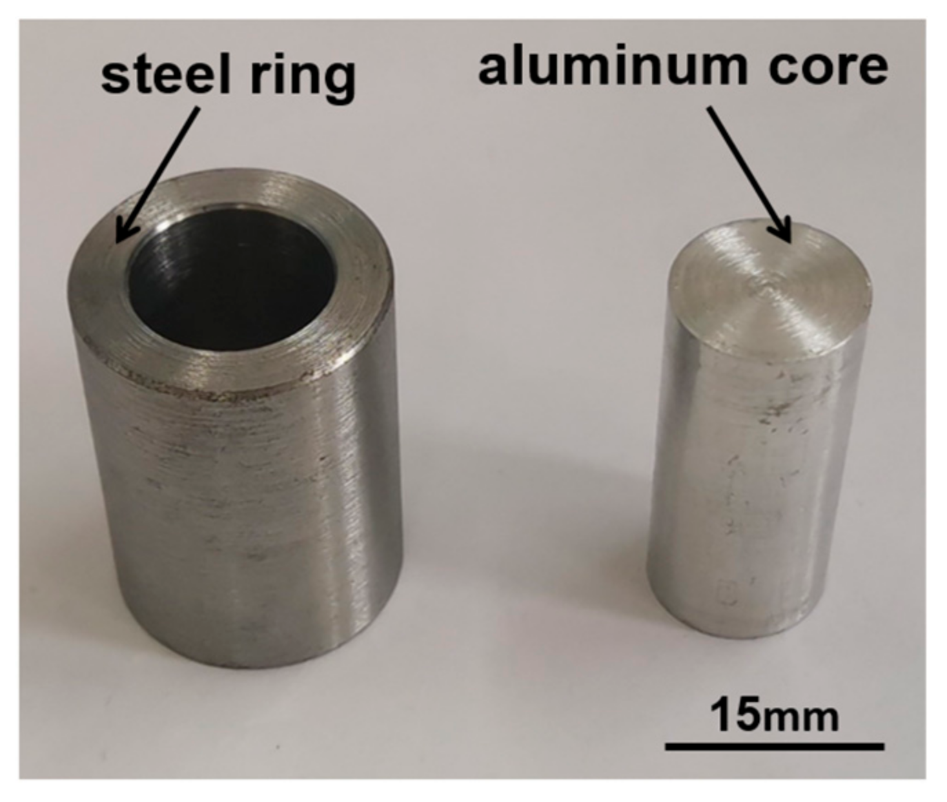
In this study, AISI 1045 medium carbon steel and 1060 aluminum alloy were selected for forming the outer teeth portion and inner core portion, respectively. Their chemical compositions are given in Table 1. The number of teeth, module, pressure angle, and teeth width of the forged steel/aluminum bimetal spur gear in this paper are 14, 2, 20° and 20 mm, respectively. The outer steel blank is designed as a ring and the inner aluminum core is designed as a solid cylinder, as shown in Figure 1. The inner diameter and outside diameter of the steel ring were designed as 14.1 mm and 22.5 mm, respectively, and the diameter of the aluminum core was designed as 14 mm. In accordance with the principle of volume constancy of the material before and after forming, the steel ring and the aluminum core have the same height of 30 mm.

Table 1.
Chemical composition (wt. %) of 1060 aluminum alloy and AISI 1045 medium carbon steel.
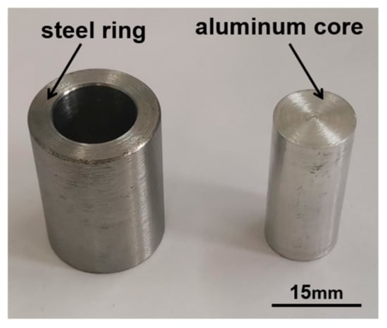
Figure 1.
Steel ring and aluminum core.
2.2. Hot Forging Process Experiment
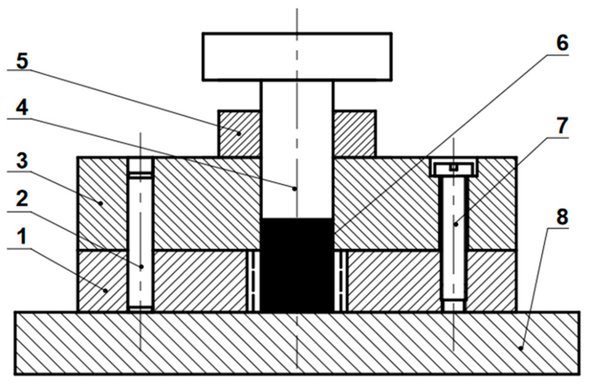
Figure 2 shows the tool structure assembly drawing for the hot forging process of the bimetal gear. The top punch was mainly used to compress the steel and aluminum alloy into the toothed die to form the gear. The pins and the screws were mainly used to fix the toothed die and the sleeve together. The role of the stop block was to control moving stroke of the top punch to avoid damage to the toothed die. When the height of the stop block is 15 mm and the stroke of the punch is 10 mm, the bimetallic billet could be fully filled into the cavity; meanwhile, the forging deformation degree of the gear is 100%. However, it is difficult for the tooth part of the gear to form in the later stage of forging, which causes the forming load to increase sharply and makes it difficult to eject the formed gear. In this research, three bimetallic gears with different degrees of deformation were forged by changing the height of the stop block; the processing plans for three bimetallic gears with different degrees of deformation are shown in Table 2.
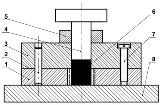
Figure 2.
Tool structure assembly drawing of the bimetal gear hot forging process: 1 toothed die, 2 pin, 3 sleeve, 4 top punch, 5 stop block, 6 billets, 7 screw, 8 workbench.
Table 2.
Processing plans of three bimetallic gears with different degrees of deformation.
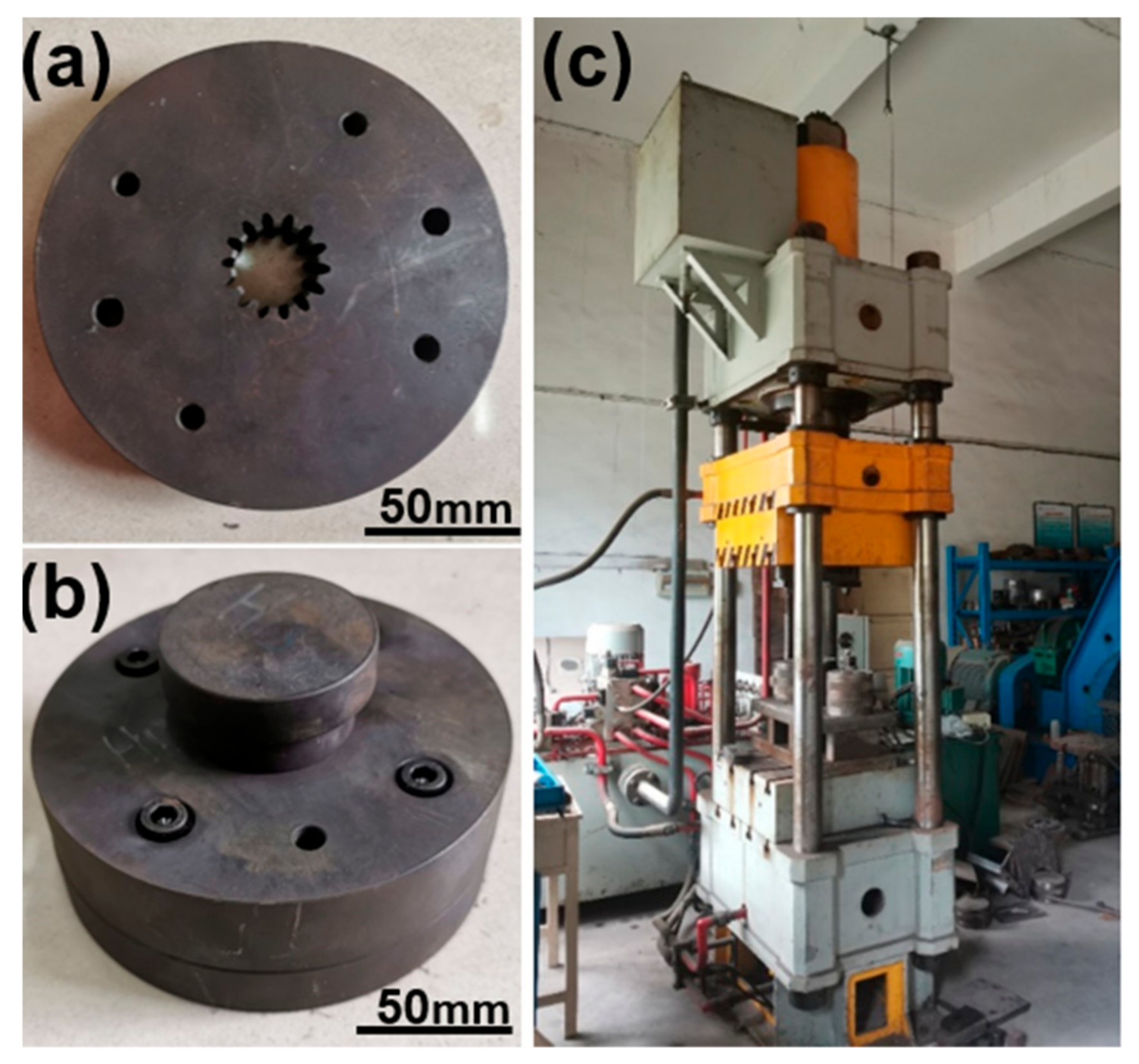
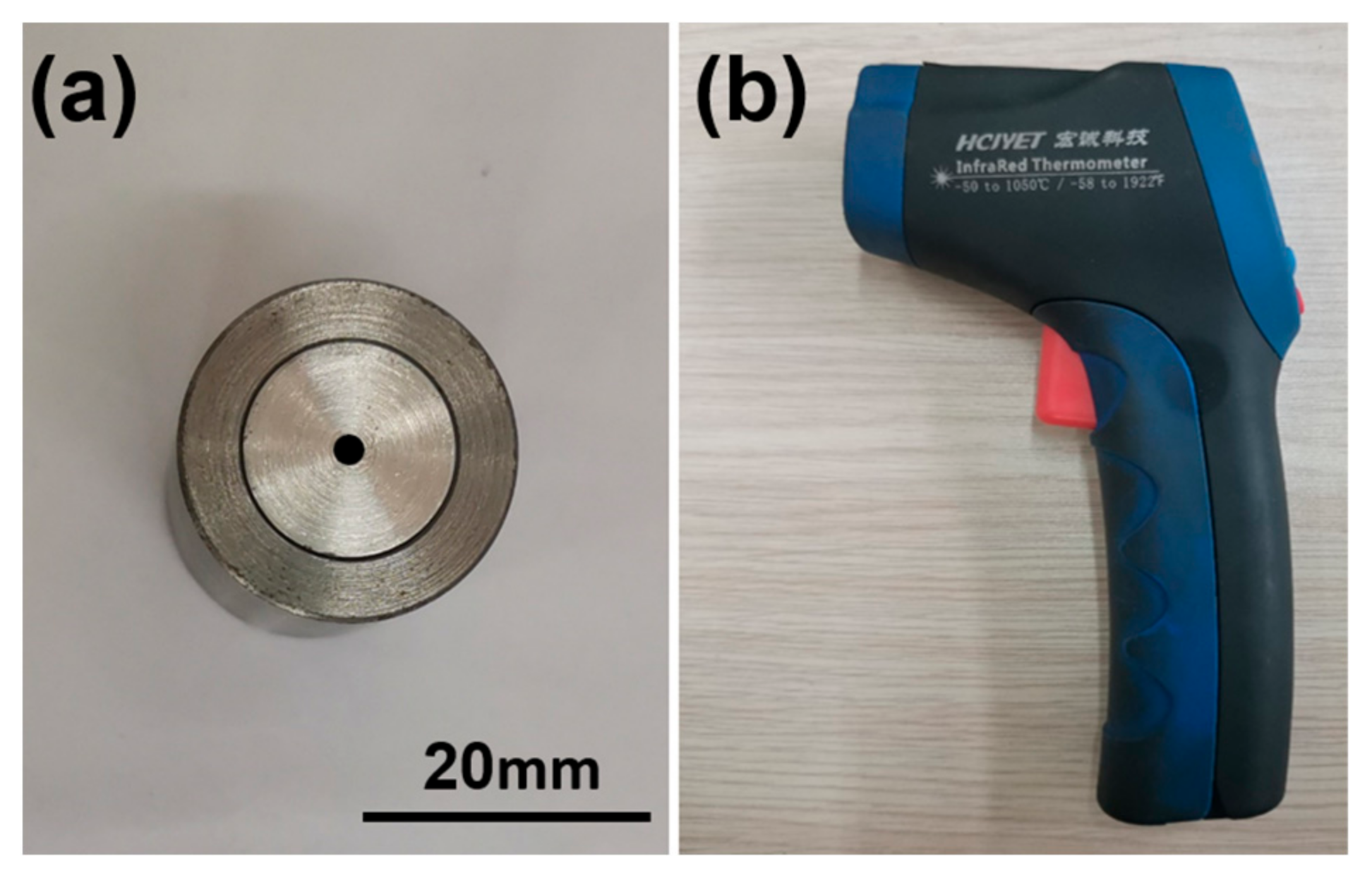
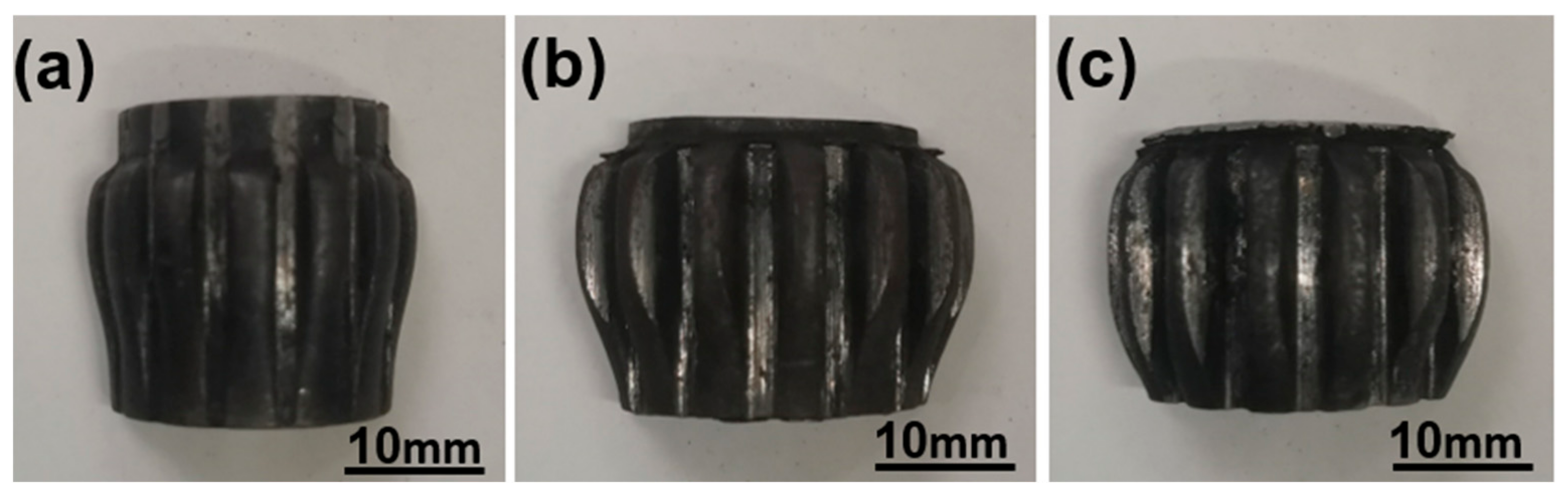
The experimental equipment is shown in Figure 3, and the toothed die was fabricated using electric discharge machining (EDM). The dies were made of H13 steel and heat treatment was carried out to improve their hardness. The hot forging experiments of steel/aluminum gear were carried out using the 160T hydraulic press (YJT26-160, Jiangdong machinery, Chongqing, China). The two billets were polished to remove any impurities existing on their surfaces. The preheating temperatures of the outer steel ring and the dies were 900 °C and 200 °C, respectively, and the temperature of the inner aluminum core was room temperature. The descending speed of the top punch was set at 5 mm/s. The central position of the top surface for each aluminum core was marked in black, as shown in Figure 4a, and the temperature at the central position was quickly measured using the infrared thermometer (HT8865, Hongcheng technology, Guangzhou, Guangdong, China) shown in Figure 4b as soon as the bimetal gear forming process was finished. Gear samples with different degrees of deformation were manufactured by replacing stop blocks with different heights, respectively, as shown in Figure 5.

Figure 3.
Experimental equipment: (a) toothed die, (b) forging die, (c) 160T hydraulic press.

Figure 4.
(a) Mark on aluminum core, (b) infrared thermometer.
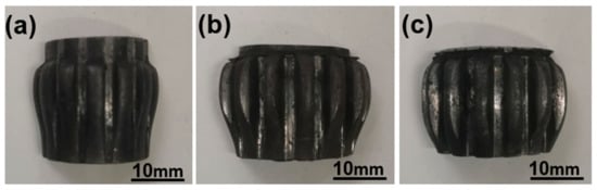
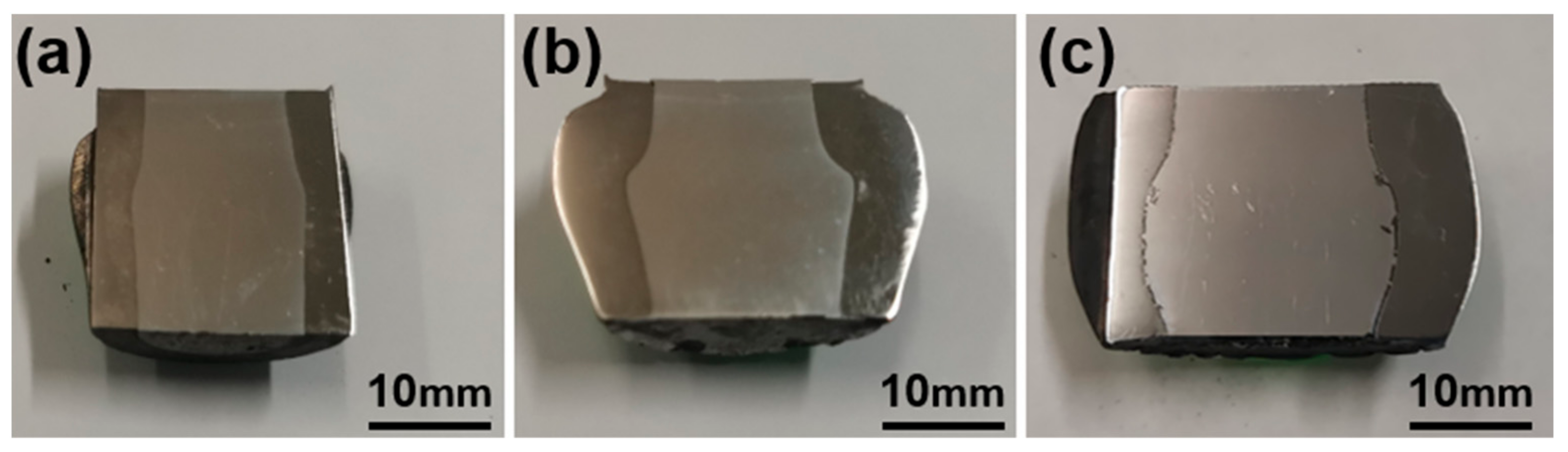
Figure 5.
Bi-metal gear samples with different degrees of deformation: (a) 50%, (b) 70%, (c) 90%.
2.3. Characterization of Interface Morphology
The steel/aluminum bimetallic gear samples were cut by EDM along the vertical cross-section and were ground and polished using metallographic sandpaper and polishing agent, as shown in Figure 6. As can be seen from Figure 6, with the increase in the degree of deformation, steel and aluminum fill the tooth die gradually, showing a classical drum-shaped expansion of cylindrical upsetting. Optical microscopy (OM, NF-120A, Precise instrument, Beijing, China), scanning electron microscopy (SEM, JSM-IT300, Oxford instruments, Abingdon, Oxfordshire, UK) and X-MaxN20 energy dispersive spectroscopy (EDS, Oxford instruments, Abingdon, Oxfordshire, UK) were used to detect morphologies and the element composition of the interface region of the bimetal gear in order to understand the interfacial bonding characteristics between steel and aluminum under different deformation degrees in detail.

Figure 6.
Vertical cross-section under different degrees of deformation: (a) 50%, (b) 70%, (c) 90%.
2.4. Simulation of Hot Forging Process
To gain a better understanding of the interface phenomenon and the stress distribution characteristics of the interface region during the hot forging process of the bimetal gear, the coupled thermo-mechanical finite element (FE) modeling for hot forging spur gear was established by DEFORM-3D V12.0 (Scientific Forming Technologies Corporation, Columbus, OH, USA) software. The one-seventh geometry models of the gear, the billets and the molds were selected to establish the FE model according to the symmetry of the spur gear to save computation time, as shown in Figure 7. According to the experimental process parameters, the temperatures of the outer steel ring, the molds and the inner aluminum core were set at 900 °C, 200 °C and 20 °C, respectively, and the descending speed of the top punch was set at 5 mm/s. The frictions at the ring–core interfaces and the billet–mold were both assumed to be of shear type and the friction factor between the steel ring and the aluminum core was set to 0.4, while friction factors between molds and the steel ring were assumed to be 0.3 and friction factors between molds and the aluminum core were assumed to be 0.4. The heat exchange boundary conditions with the environment were defined in order to guarantee the prediction accuracy of the FE model. The environment temperature was set 20 °C and the thermal conductivity and heat capacity and emissivity of AISI 1045 steel and 1060 aluminum were defined. The surface heat transfer coefficient and convection coefficient were defined to calculate the heat exchange between the ambient atmosphere and the contacting object. The surface heat transfer coefficient between the steel ring and molds was set as 5 N/(s·mm·°C), while the surface heat transfer coefficient between the aluminum core and the steel ring and the molds was defined as 11 N/(s·mm·°C), and the convection coefficient was defined as 0.02 N/(s·mm·°C).
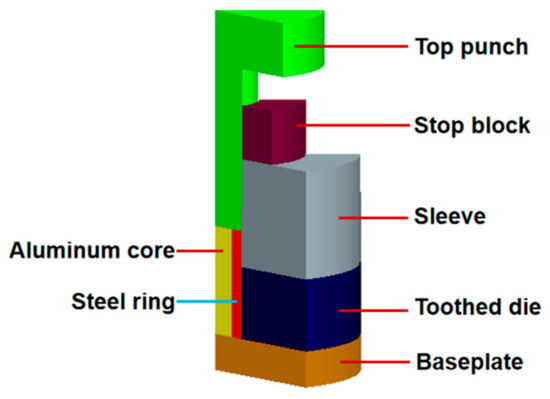
Figure 7.
The thermo-mechanical coupled FE model for hot forging steel/aluminum spur gear.
3. Results and Discussion
3.1. Microscopic Analyses of Interface
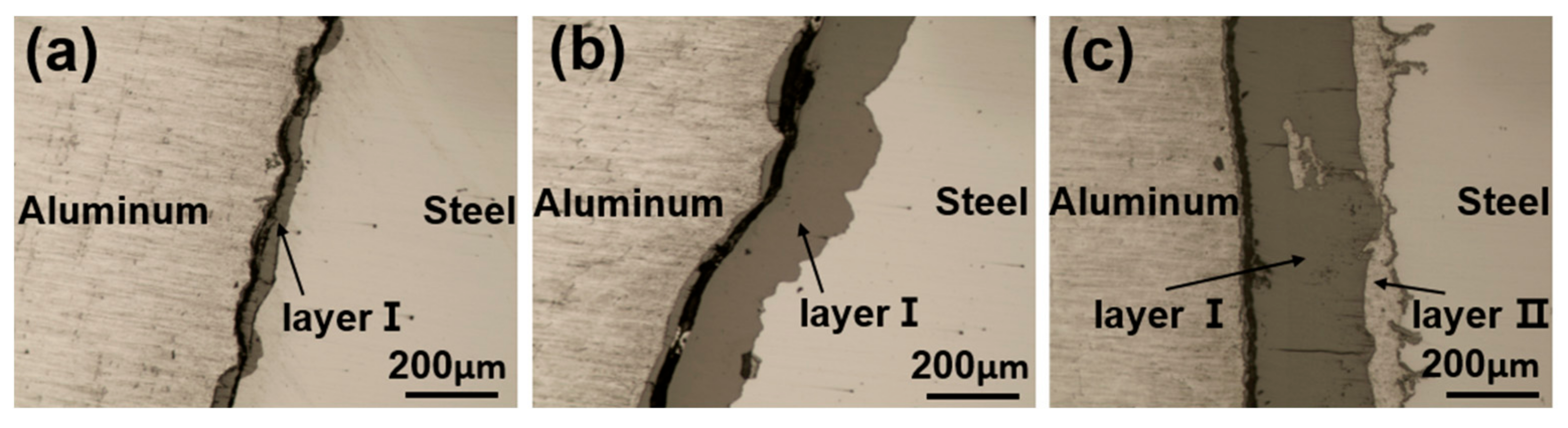
Metallographic analysis was used for the examination of interface layers between steel and aluminum in bimetal gears forged with different degrees of deformation. Figure 8 shows micrographs of the joining zone between steel and aluminum under different deformation degrees, steel–aluminum joining layer I gradually thickens as the deformation proceeds, and in optical microscopy, interfacial layer I is distinctly different from the base materials as a result of its different color. There is a dark substance along the interface zone close to the aluminum side. In addition, when the deformation degree of the gear is 90%, there is layer II with a color similar to that of aluminum alloy along the interface zone close to the steel side, as shown in Figure 8c.
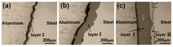
Figure 8.
Micrographs of the joining zone between steel and aluminum under different deformation degrees: (a) 50%, (b) 70%, (c) 90%.
In order to characterize the steel–aluminum joint in detail, the bimetal gear with 90% deformation degree was investigated by means of scanning electron microscopy (SEM); there is a distinct difference in color between the SEM micrograph and the OM micrograph of the interlayers and matrix by comparing Figure 8 with Figure 9. In order to further determine the composition of the joint zone, EDS analysis of seven points at different locations of the joining zone between steel and aluminum was performed, including point 1, 2, 3, 4, 5, 6 and 7, as shown in Figure 9, and the results are shown in Table 3. The results from points 2 to 5 indicate that layer I is composed of iron oxides, which is a product of the oxide film formed during the preheating process of steel. The dark substance next to the Al side is a mechanical mixture consisting of iron oxides, aluminum oxides and aluminum alloys according to the atom ratios of point 1. The results of points 6 and 7 show that the aluminum alloy passes through the oxide film of layer I and contacts the steel side at the late stage of forging, where layer II was formed. In addition, the elemental compositions of points a and b next to the Al and steel side in Figure 9 were also measured by means of the EDS; they are 100% Al atom ratio and 100% Fe atom ratio, respectively.
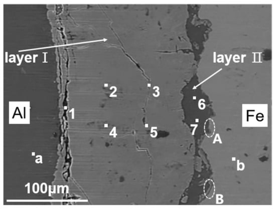
Figure 9.
SEM micrograph of the joining zone between steel and aluminum of the gear with 90% deformation degree.
Table 3.
The element composition of seven points in the joint zone by EDS spectrum analysis (at %).
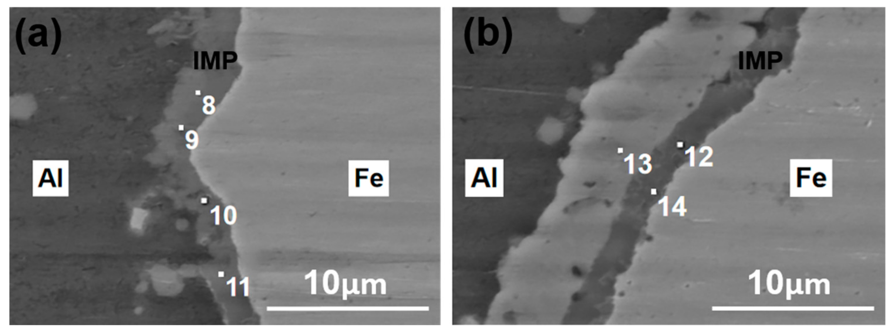
In order to further analyze interfacial bonding characteristics of steel/aluminum bimetal gears, positions A and B in the interface regions between the steel and layer II were examined using SEM and EDS analysis, as shown in Figure 9. Figure 10 shows that a complete bond without gaps was observed in the joining zone between steel and aluminum; moreover, the diffusion of Al and Fe occurs at the bonding zone according to the EDS spectrum analysis results of points 8–12 and 14 in Table 4. The increase in contact pressure and plastic deformation intensifies the diffusion of Al and Fe at high temperature and ensures a reliable metallurgical bond between both base materials. The SEM-EDS analysis results showed that the intermetallic phases (IMP) formed an interface between the steel and layer II, and their color is different compared to the two base materials [24,25]. The scanning results from points 12–14 indicate that residual iron oxides prevented the diffusion of Al into Fe and the reduction in the aluminum atom ratio in intermetallic compounds is more obvious. Figure 10 shows that the IMP can form at the interface between the aluminum alloy and steel after the aluminum alloy passed through the oxide film and contacted the Fe side, and the thickness of IMP is about 1.5–3.9 μm.

Figure 10.
SEM micrograph of the joining zone between steel and layer II: (a) position A, (b) position B.
Table 4.
The element composition of points 8 to 14 in the joint zone by EDS spectrum analysis (at %).
3.2. Interfacial Bonding Characteristics of Bi-Metal Gears
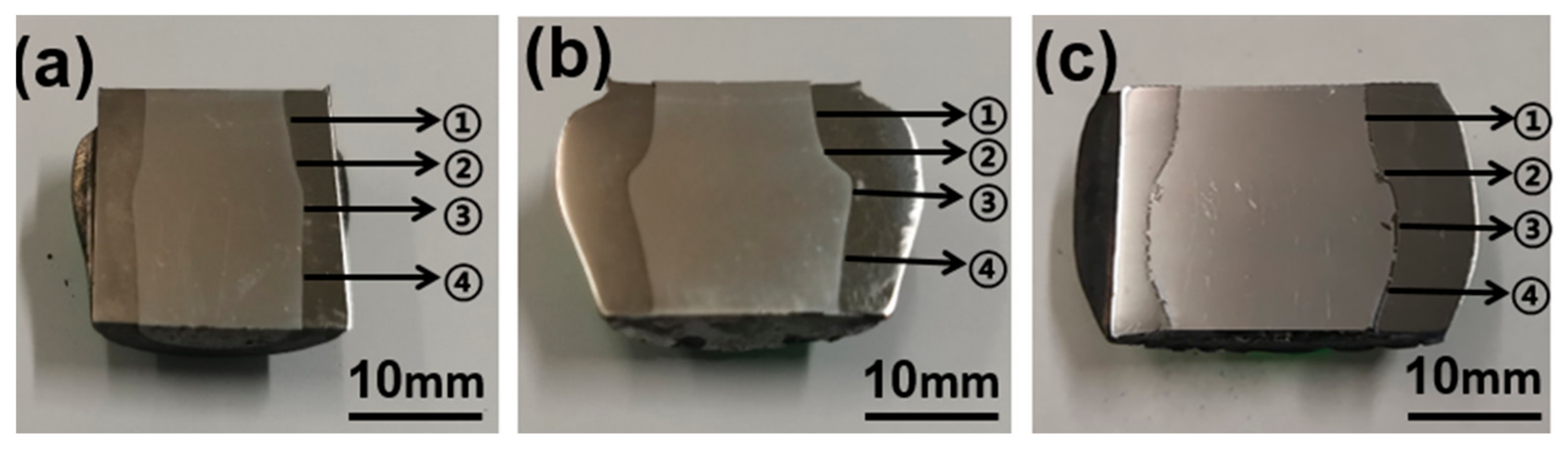
In order to investigate the interface bonding characteristics of bimetal gears under different degrees of deformation, the optical microscope was used to observe each gear interface along the drum-shape contour, and four positions were selected for discussion, including position ①, ②, ③ and ④, as shown in Figure 11.
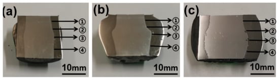
Figure 11.
Measurement positions of the gears under different degrees of deformation: (a) 50%, (b) 70%, (c) 90%.
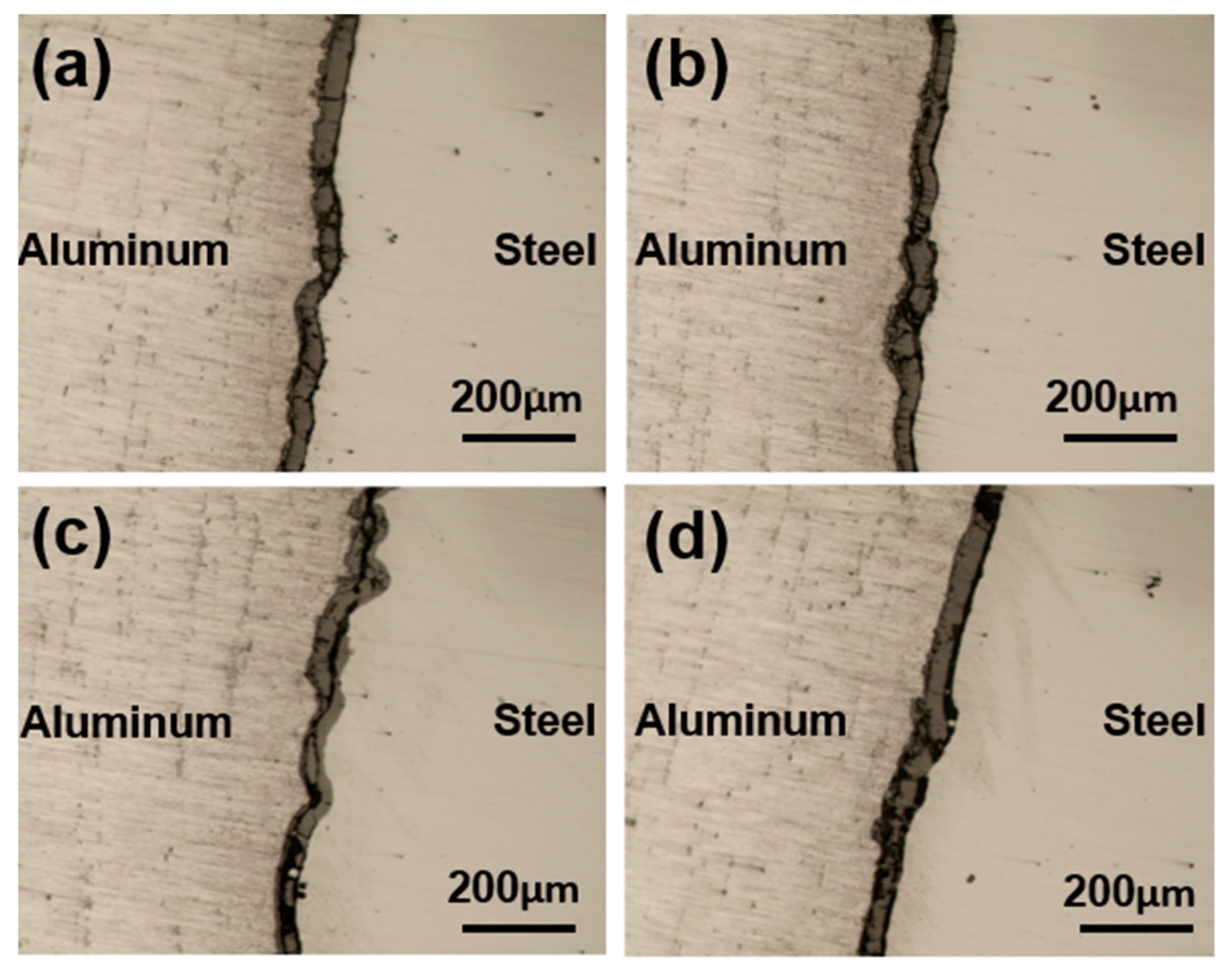
Figure 12, Figure 13 and Figure 14 illustrate the interface micrographs of the steel/aluminum bimetal gears forged under different deformation degrees. As can be seen from Figure 12, Figure 13 and Figure 14, there are both oxide layer joint zones between steel and aluminum under different gear deformation, and the width of the joint zones increases with the increase in deformation degree. In addition, the color of the joint zone is also different with the increase in deformation degree, which indicates the formation of dissimilar intermetallic compound.
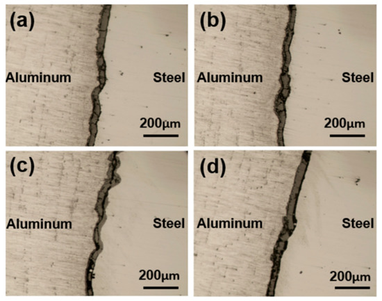
Figure 12.
Interface micrographs of the bimetal gear with deformation degree of 50%: (a) position ①, (b) position ②, (c) position ③, (d) position ④.
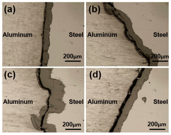
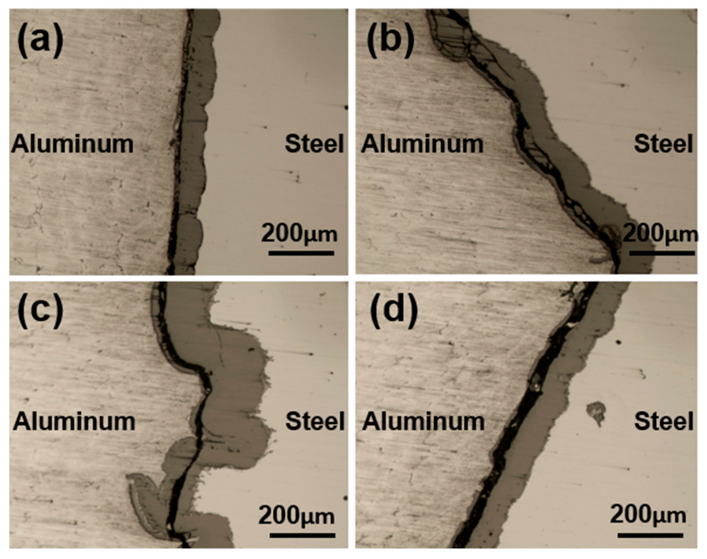
Figure 13.
Interface micrographs of the bimetal gear with deformation degree of 70%: (a) position ①, (b) position ②, (c) position ③, (d) position ④.
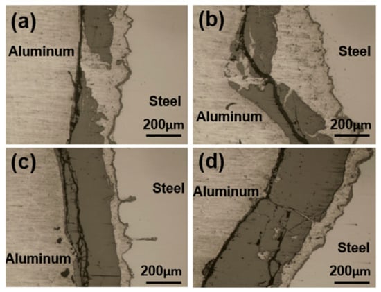
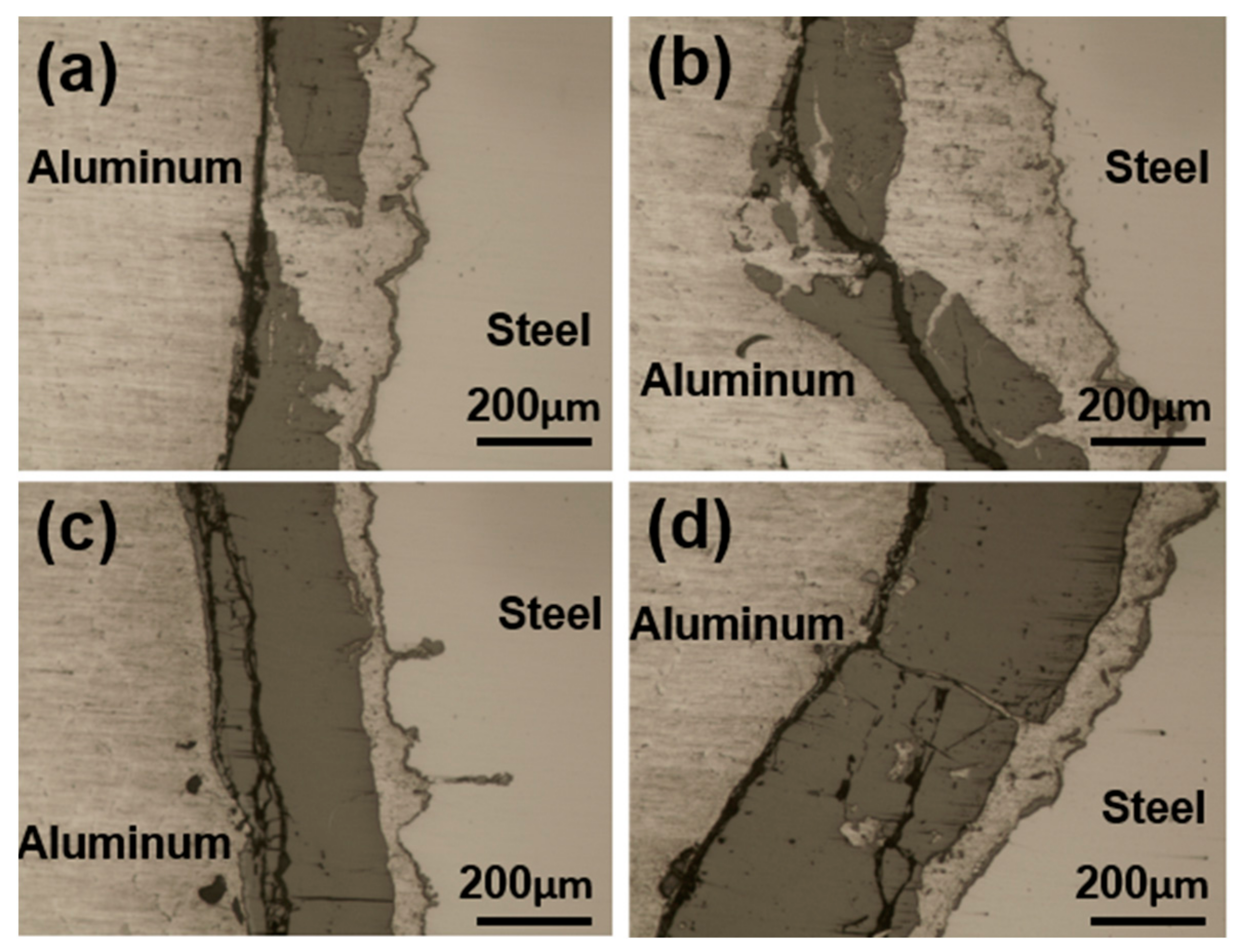
Figure 14.
Interface micrographs of the bimetal gear with deformation degree of 90%: (a) position ①, (b) position ②, (c) position ③, (d) position ④.
When the gear deformation degree is 50%, there is the iron oxide layer along the interface between both base materials, as shown in Figure 12. The width of the iron oxide layer is relatively uniform in each position, but a large amount of dark material appears in the middle of the oxide layer in position ③ due to larger plastic deformation in the middle of the drum shape, as seen in Figure 12c. There were no intermetallic compounds in the joining zone between steel and aluminum as a result of the barrier effect of the iron oxide layer, which shows that a mechanical bonding between steel and aluminum is achieved when the gear deformation degree is 50%.
When the gear deformation degree is 70%, the width of the iron oxide layer at various points increases obviously, especially at position ③, as shown in Figure 13. This is because the contact surface enlarges with increasing deformation degree, and normal and shear stresses in the interface zone intensify the fracture in the brittle oxide layer [26]. A lot of the iron oxide accumulated along the interface, resulting in an increase in the thickness of the iron oxide layer. A black mechanical mixture is formed between the iron oxide layer and the aluminum alloy, and it is composed of iron oxide, aluminum oxide and pure aluminum. There are still no intermetallic compounds in the joining zone between steel and aluminum due to the barrier effect of the iron oxide layer, which indicates that a mechanical joint between steel and aluminum is achieved when the gear deformation degree is 70%.
As shown in Figure 14, when the gear deformation degree is 90%, the iron oxide layer continues to widen, but fractures of the iron oxide layer are intensified sharply as the deformation proceeds. Aluminum alloy passed through the oxide film to the steel side due to the increase in normal stresses in the interface zone. According to the results in Section 3.1, when the gear deformation degree is 90%, the IMP formed in the bonding zone between steel and aluminum next to the iron substrate. Meanwhile, the intermixing of the aluminum matrix and the iron oxides results in mechanical occlusion, which is beneficial for increasing the interfacial bonding strength, as shown in Figure 14a. Besides the metallic bond, the wavy interface could provide an assistant mechanical lock to the two kinds of matrix materials, which is beneficial to the interface bonding of the bimetal gear [27]. It can be stated that the metallurgical joint has been formed locally at the steel–aluminum joining zone at a degree of deformation of 90% during the hot forging process of bimetal gear.
3.3. Finite Element Analysis
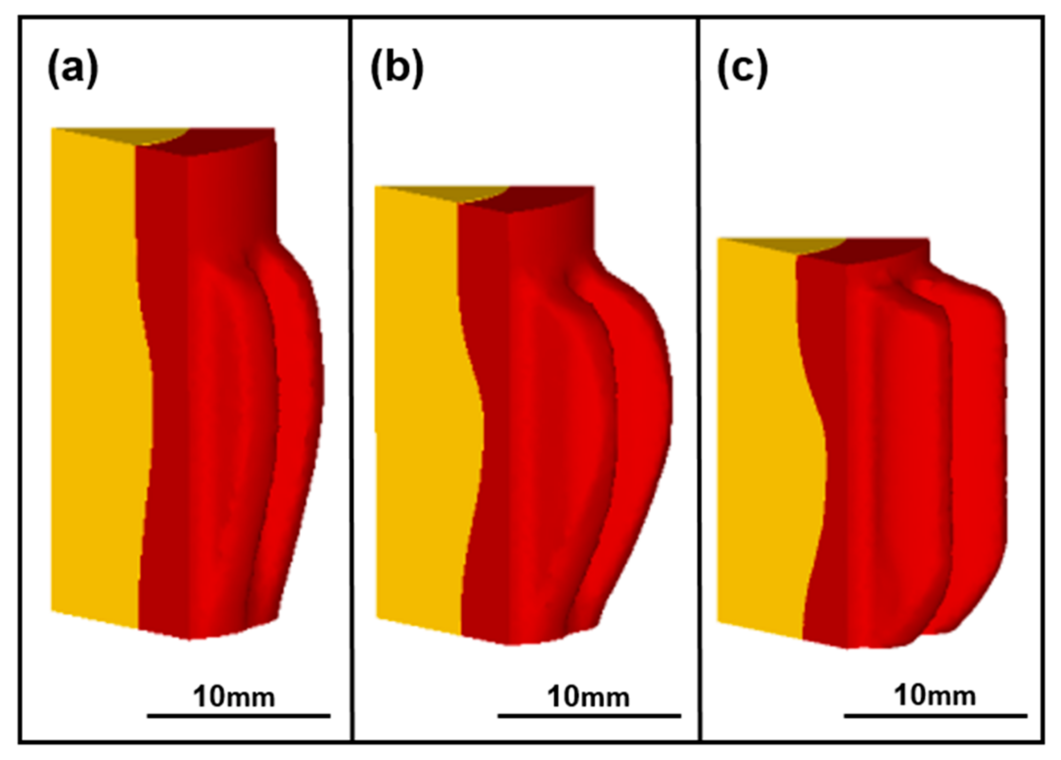
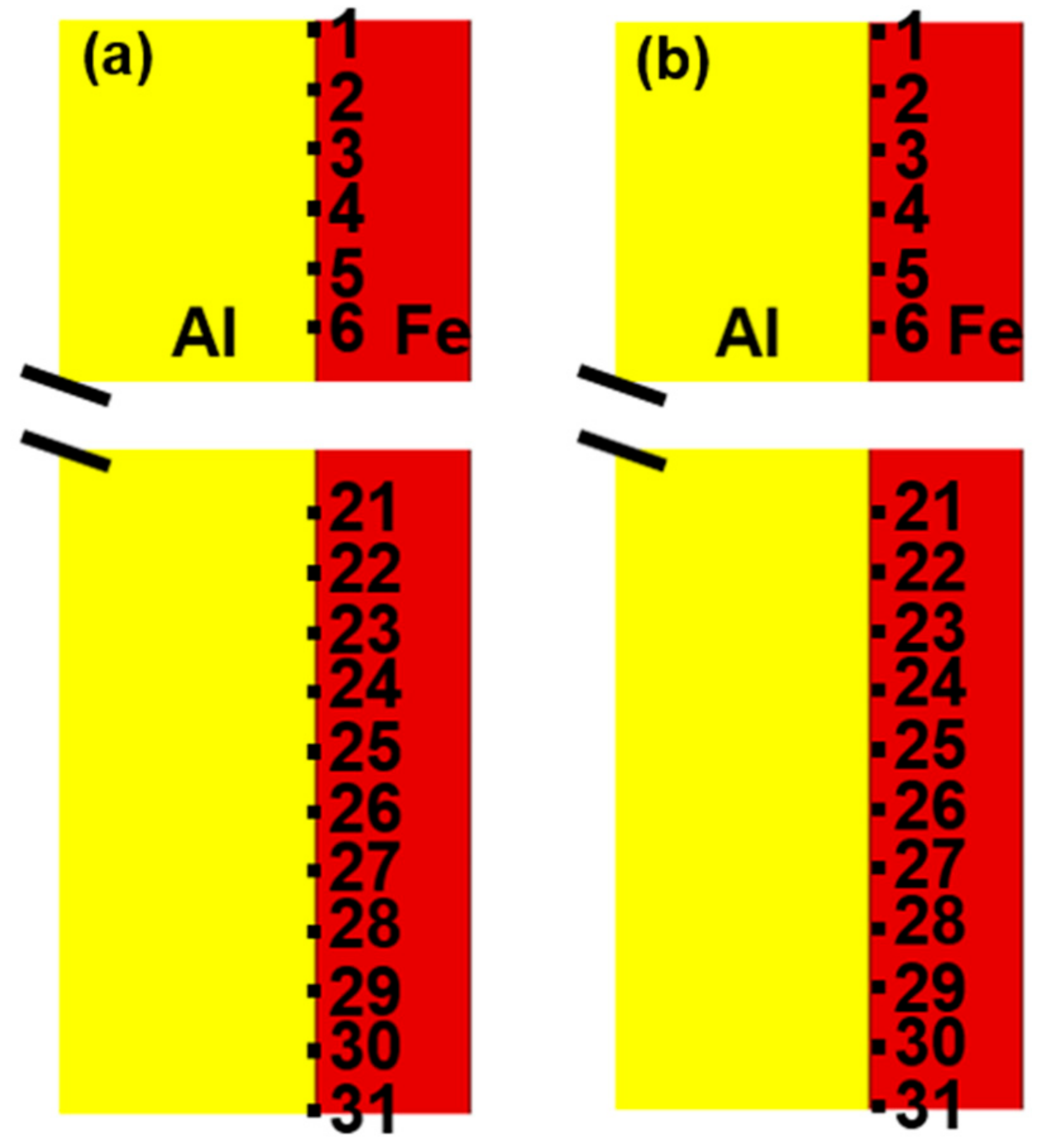
In order to analyze heat transfer and stress distribution at the interface of bimetallic gears, finite element (FE) simulation of hot forging process was carried out by using DEFORM-3D software. Figure 15 shows the interface profile and the filling of tooth profile of bimetal gears under different degrees of deformation. The red part is steel and the yellow part is pure aluminum. As can be seen from Figure 15, steel and aluminum fill the tooth die gradually with the increase in the degree of deformation and the interface profiles show a classical drum-shaped expansion, which is in good agreement with the experimental results, as shown in Figure 5 and Figure 6. The temperature at the central position of the top surface of the aluminum core with different degrees of deformation was extracted by the DEFORM-3D software. The experimental and simulation results are shown in Table 5, the maximum temperature difference between simulation and experiment is 5 °C, which shows that the temperature predicted by FE simulation is reliable. In order to study the interface characteristics in detail, 31 points were selected on the interface of the aluminum core and steel ring along the heights of billets by using the point-tracking method; points 1 and 31 are situated at the top surface and bottom surface, respectively, and all the 31 points were selected at equal spacing distance, as shown in Figure 16a,b, respectively. Based on the finite element simulation results, the interface temperature and normal stress of each point under different degrees of deformation were extracted, respectively, as shown in Figures 17 and 19.
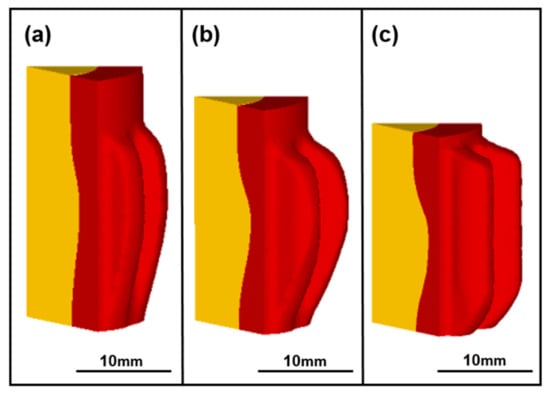
Figure 15.
Simulation results of bimetal gears with different degrees of deformation: (a) 50%, (b) 70%, (c) 90%.
Table 5.
Temperature at the central position of aluminum core.
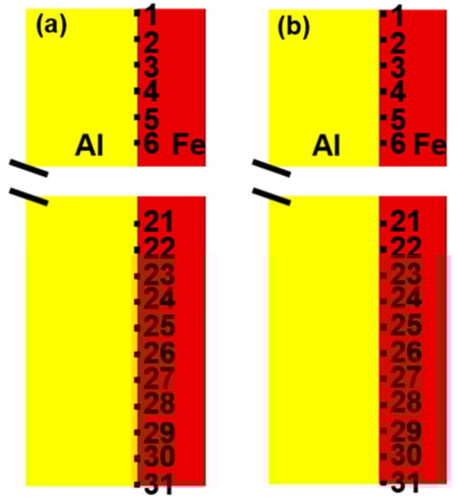
Figure 16.
Tracking points: (a) the aluminum interface, (b) the steel interface.
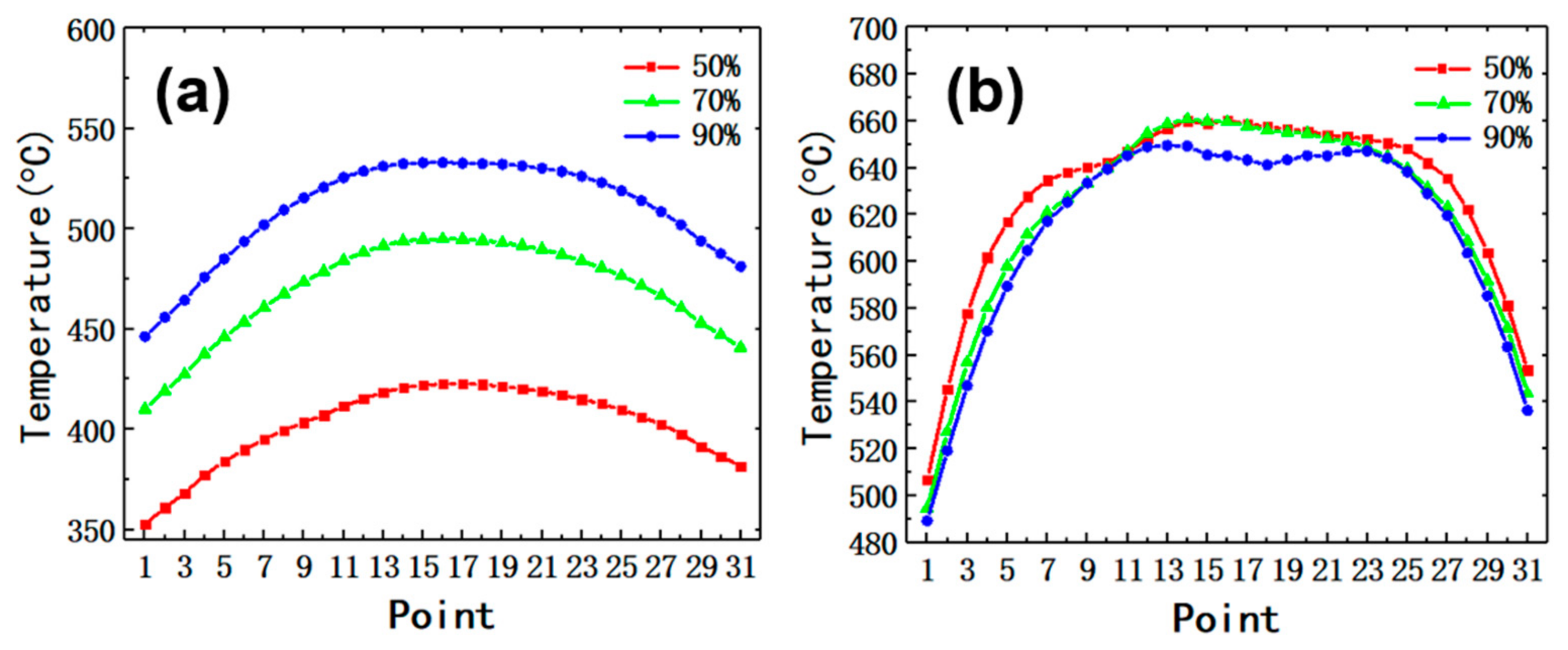
Figure 17 shows the interface temperature of aluminum- and steel-forming gears with different degrees of deformation. As can be seen from Figure 17, the interface temperature of aluminum and steel at the central position is higher than that at the upper and lower end. This is because the upper and lower parts of the gear are in direct contact with the mold. As can also be seen in Figure 17, the interface temperature of aluminum increases continuously and the interface temperature of the steel drops slowly with the increase in the deformation degree of the gear. When the deformation degree of the gear is 90%, the interface temperature of aluminum is about 450–530 °C and the interface temperature of steel is about 490–650 °C. The increasing interface temperature of aluminum helps to strengthen the diffusion of aluminum at the interface during hot forging of bimetal gear. In addition, the interface temperature affects the flow stress of metal.
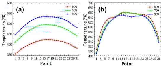
Figure 17.
Distribution of temperature of interface between aluminum and steel under different degrees of deformation: (a) aluminum, (b) steel.
The experimental results of hot forging of bimetallic gear show that the increase in plastic deformation of the base materials leads to the fracture of oxide film, which is conducive to the metallurgical bonding between aluminum and steel. The plastic deformation of the base metal is closely related to the flow stress distribution at the interface, so it is necessary to study the distribution of the flow stress of two base materials along the interface. When the deformation degree of the gear exceeds 50%, the temperature of aluminum at the interface is above 350 °C, as seen in Figure 17a. According to flow stress–strain curves of 1060 aluminum alloy at different strain rates [28], when the temperature of aluminum is above 350 °C, its flow stress is below 150 MPa. In addition, the flow stress of the aluminum at the interface decreases continuously with the increase in temperature.
According to reference [29], the flow stress model of AISI 1045 steel can be presented using Equations (1)–(6):
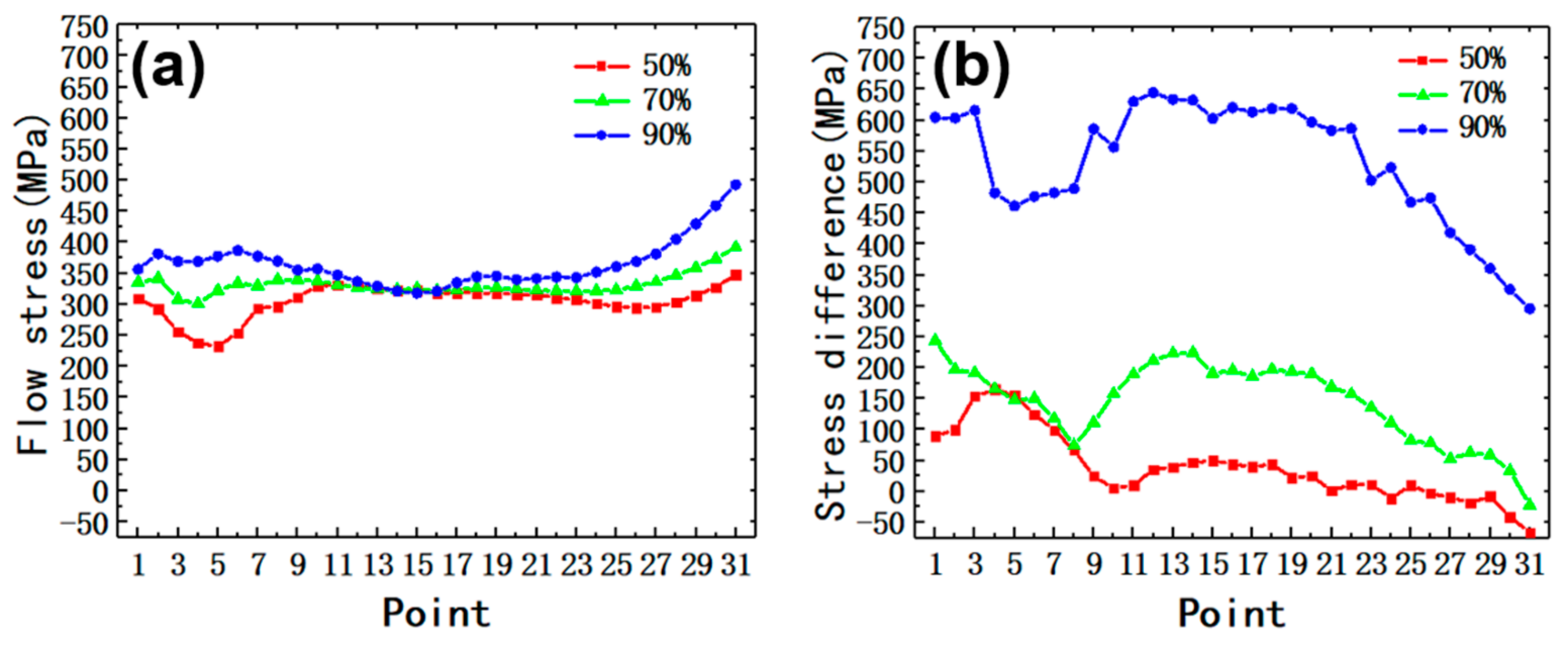
where σ is the flow stress, σp is the peak stress, σdrec is the extensional stress without considering the recrystallization, Z is the Zener–Hollomon parameter, ε is the equivalent plastic strain, εc is the critical strain, is the equivalent strain rate and T is the interface temperature of steel. The flow stress at the interface was calculated by extracting the strain, strain rate and temperature using the point-tracking method, and the flow stress distribution along the interface is shown in Figure 18a. It is stated, in accordance with Figure 18a, that the flow stress of the steel at the interface is above 220 MPa when the deformation degrees of the gear exceed 50% and the flow stress of steel is always much greater than that of aluminum. The increase in metal flow stress will hinder its plastic deformation at the interface, so the deformation resistance of the steel is the main hindrance to interface bonding, which is consistent with the experimental phenomenon. The flow stress of the steel at the interface is above 300 MPa when the deformation degree of the gear is 90%.
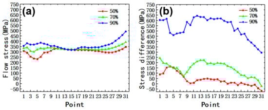
Figure 18.
(a) The flow stress of AISI 1045 steel; (b) the difference between radial stress and flow stress of AISI 1045 steel.
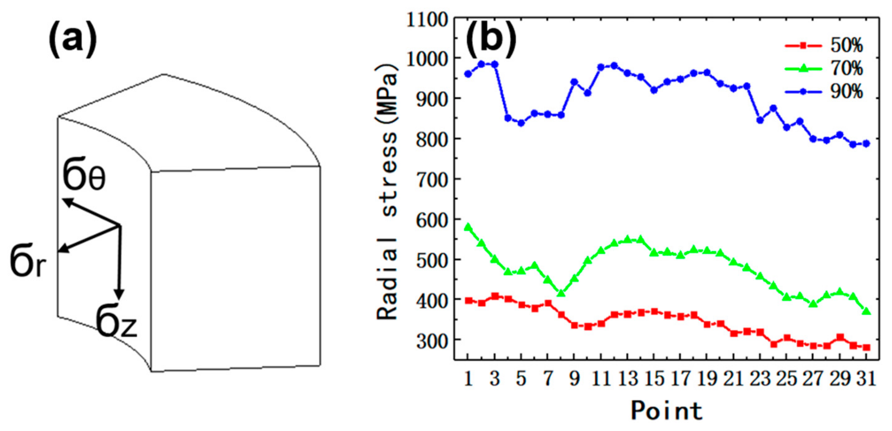
The contact normal stress also plays a very important role during the formation of the interface bond [17], so it is necessary to study the contact normal stress of two base materials along the interface. In this study, the bimetal gear forging process is axisymmetric forming, the cylindrical coordinate system is selected to analyze the interface contact stress distribution between steel and aluminum, and the contact stress is decomposed into axial stress, circumferential stress and radial stress, as shown in Figure 19a, in which the radial stress is equivalent to the contact normal stress of the interface. Figure 19b shows the interface radial stress, as can be seen from Figure 19b, the interface radial stress increases with the increase in deformation degree and rises sharply in the later period of forging due to the increase in flow resistance of the billet filling the tooth part of the gear, which is consistent with the growth trend of the forming load. When the deformation degree of the gear is 90%, the interface radial stress is above 800 MPa. The increase in radial stress is the key to the rupture of the oxide film and the formation of IMP.
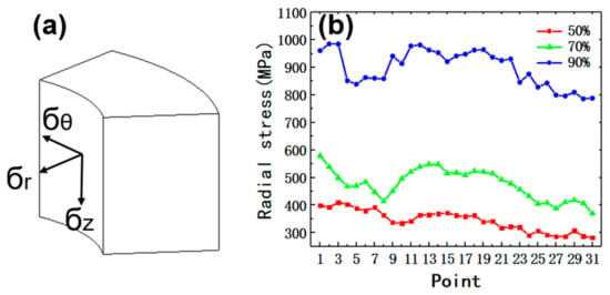
Figure 19.
(a) Stress element in a cylindrical coordinate system, (b) radial stress at interface.
It is favorable for plastic deformation of steel and fractures of oxide layers when the radial stress at the interface is greater than the flow stress of the steel. Figure 18b shows the difference between radial stress and flow stress of the steel at the interface. When the stress difference is less than 0, the radial stress is lower than the steel flow stress. As can be seen from Figure 18b, the stress difference increases with the increase in gear deformation degree and the value is above 300 MPa when the deformation degree of the gear is 90%. According to the experiment results in Section 3.2, the bonding between steel and aluminum is mechanical when the deformation degree is 50% and 70%, and the metallurgical bond has been formed locally at the steel–aluminum joining zone when the deformation degree is 90%, which shows the increase in the difference between the interfacial radial stress and the flow stress of AISI 1045 steel contributes to the formation of a metallurgical bond at the steel–aluminum joining zone.
4. Conclusions
In this study, bimetal gears have been forged using the AISI-1045 steel and the 1060 aluminum alloy. The interfacial bonding characteristics of bimetal gears with different degrees of deformation were investigated by means of OM, SEM and EDS. The heat transfer and stress distribution at the interface of bimetallic gears were analyzed by using DEFORM-3D software. The following conclusions are made:
- (1).
- The width of the iron oxide layer along the interface zone increases with the increase in gear deformation degree.
- (2).
- The bonding between steel and aluminum is mechanical when the deformation degree is 50% and 70% and the metallurgical bond has been formed locally at the steel–aluminum joining zone when the deformation degree is 90%.
- (3).
- The increase in the difference between the interfacial radial stress and the flow stress of the AISI 1045 steel contributes to the formation of metallurgical bonds at the steel–aluminum joining zone.
Author Contributions
Z.M. and W.F. conceived and designed this study and wrote the paper, X.J. conducted the experiments and wrote the paper, W.Z. and M.W. provided experimental supports. All authors have read and agreed to the published version of the manuscript.
Funding
This research was supported by National Natural Science Foundation of China (No.51475344), National Natural Science Foundation of China (No. 52005375) and China Postdoctoral Science Foundation (No. 2020M672429).
Institutional Review Board Statement
Not applicable.
Informed Consent Statement
Not applicable.
Data Availability Statement
Data is contained within the article.
Acknowledgments
The authors gratefully acknowledge the financial support of National Natural Science Foundation of China (No.51475344), National Natural Science Foundation of China (No. 52005375) and China Postdoctoral Science Foundation (No. 2020M672429).
Conflicts of Interest
The authors declare no conflict of interest.
References
- Groche, P.; Wohletz, S.; Brenneis, M.; Pabst, C.; Resch, F. Joining by forming—A review on joint mechanisms, applications and future trends. J. Mater. Processing Technol. 2014, 214, 1972–1994. [Google Scholar] [CrossRef]
- Behrens, B.A.; Bistron, M.; Kueper, A.; Moehwald, K. Investigation of load adapted gears and shafts manufactured by compound-forging. J. Adv. Manuf. Syst. 2008, 7, 175–182. [Google Scholar] [CrossRef]
- Politis, D.J.; Lin, J.; Dean, T.A.; Balint, D.S. An investigation into the forging of Bi-metal gears. J. Mater. Processing Technol. 2014, 214, 2248–2260. [Google Scholar] [CrossRef]
- Wu, P.; Wang, B.; Lin, J.; Zuo, B.; Zhou, J. Investigation on metal flow and forming load of bi-metal gear hot forging process. Int. J. Adv. Manuf. Technol. 2017, 88, 2835–2847. [Google Scholar] [CrossRef]
- Chavdar, B.; Goldstein, R.; Ferguson, L. Hot hydroforging of lightweight bimaterial gears and hollow products. In Proceedings of the 23rd IFHTSE World Congress, Savannah, GA, USA, 18–21 April 2016. [Google Scholar]
- Yılmaz, T.G.; Doğan, O.; Karpat, F. A comparative numerical study of forged bi-metal gears: Bending strength and dynamic response. Mech. Mach. Theory 2019, 141, 117–135. [Google Scholar] [CrossRef]
- Behrens, B.A.; Kosch, K.G. Development of the heating and forming strategy in compound forging of hybrid steel-aluminum parts. Mater. Und Werkst. 2011, 42, 973–978. [Google Scholar] [CrossRef]
- Behrens, B.A.; Kosch, K.G. Production of Strong Steel-Aluminum Composites by Formation of Intermetallic Phases in Compound Forging. Steel Res. Int. 2011, 82, 1261–1265. [Google Scholar] [CrossRef]
- Springer, H.; Kostka, A.; Santos, J.F.; Raabe, D. Influence of intermetallic phases and Kirkendall-porosity on the mechanical properties of joints between steel and aluminium alloys. Mater. Sci. Eng. A 2011, 528, 4630–4642. [Google Scholar] [CrossRef]
- Yamamoto, N.; Takahashi, M.; Aritoshi, M.; Ikeuchi, K. Formation of intermetallic compounds in friction bonding of Al alloys to steel. Materials science forum. Mater. Sci. Forum 2007, 539, 3865–3871. [Google Scholar] [CrossRef]
- Yang, Y.C.; Zhang, F.Y.; Qin, Y.F.; He, J.; Liu, B.X.; Yang, M.X.; Yin, F.X. Microstructure, growth kinetics and mechanical properties of interface layer for roll bonded aluminum-steel clad sheet annealed under argon gas protection. Vacuum 2018, 151, 189–196. [Google Scholar] [CrossRef]
- Kim, H.J.; Kim, T.H.; Shin, J.S.; Park, S.Y.; Hyun, S.; Lim, K.M. Effect of Surface Treatments on Cast-Bonding Characteristics of Steel-Aluminum Hybrid Composite Materials. Arch. Metall. Mater. 2019, 64, 889–892. [Google Scholar] [CrossRef]
- Mirza, F.A.; Macwan, A.; Bhole, S.D.; Chen, D.L.; Chen, X.G. Effect of welding energy on microstructure and strength of ultrasonic spot welded dissimilar joints of aluminum to steel sheets. Mater. Sci. Eng. A 2016, 668, 73–85. [Google Scholar] [CrossRef]
- Xu, L.; Wang, L.; Chen, Y.C.; Robson, J.; Prangnell, P. Effect of interfacial reaction on the mechanical performance of steel to aluminum dissimilar ultrasonic spot welds. Metall. Mater. Trans. A 2016, 47, 334–346. [Google Scholar] [CrossRef]
- Aizawa, Y.; Nishiwaki, J.; Harada, Y.; Muraishi, S.; Kumai, S. Experimental and numerical analysis of the formation behavior of intermediate layers at explosive welded Al/Fe joint interfaces. J. Manuf. Processes 2016, 24, 100–106. [Google Scholar] [CrossRef]
- Kaya, Y. Microstructural, mechanical and corrosion investigations of ship steel-aluminum bimetal composites produced by explosive welding. Metals 2018, 8, 544. [Google Scholar] [CrossRef]
- Groche, P.; Wohletz, S.; Erbe, A.; Altin, A. Effect of the primary heat treatment on the bond formation in cold welding of aluminum and steel by cold forging. J. Mater. Processing Technol. 2014, 214, 2040–2048. [Google Scholar] [CrossRef]
- Akramifard, H.R.; Mirzadeh, H.; Parsa, M.H. Estimating interface bonding strength in clad sheets based on tensile test results. Mater. Des. 2014, 64, 307–309. [Google Scholar] [CrossRef]
- Chen, G.; Xu, G. Effects of melt pressure on process stability and bonding strength of twin-roll cast steel/aluminum clad sheet. J. Manuf. Processes 2017, 29, 438–446. [Google Scholar] [CrossRef]
- Hosseini, M.; Pardis, N.; Manesh, H.D.; Abbasi, M.; Kim, D. Structural characteristics of Cu/Ti bimetal composite produced by accumulative roll-bonding (ARB). Mater. Des. 2017, 113, 128–136. [Google Scholar] [CrossRef]
- Babaee, M.H.; Niroumand, B.; Maleki, A.; Lashani, Z.M. Simulation and experimental verification of interfacial interactions in compound squeeze cast Al/Al–Cu macrocomposite bimetal. Trans. Nonferrous Met. Soc. China 2019, 29, 950–963. [Google Scholar] [CrossRef]
- Babaee, M.H.; Maleki, A.; Niroumand, B. A novel method to improve interfacial bonding of compound squeeze cast Al/Al− Cu macrocomposite bimetals: Simulation and experimental studies. Trans. Nonferrous Met. Soc. China 2019, 29, 1184–1199. [Google Scholar] [CrossRef]
- Rezaii, A.; Shafiei, E.; Ostovan, F.; Daneshmanesh, H. Experimental & theoretical investigation of roll bonding process of multilayer strips by finite element method. J. Manuf. Processes 2020, 54, 54–69. [Google Scholar] [CrossRef]
- Carvalho, G.; Galvão, I.; Mendes, R.; Rui, M. Leal Aluminum-to-steel cladding by explosive welding. Metals 2020, 10, 1062. [Google Scholar] [CrossRef]
- Yu, X.; Fan, D.; Huang, J.; Li, C.L.; Kang, Y.T. Arc-assisted laser welding brazing of aluminum to steel. Metals 2019, 9, 397. [Google Scholar] [CrossRef]
- Bay, N.; Clemensen, C.; Juelstorp, O. Bond strength in cold roll bonding. CIRP Ann. 1985, 34, 221–224. [Google Scholar] [CrossRef]
- Zhang, Z.; Xu, W.; Gu, T.; Shan, D. Fabrication of steel/aluminum clad tube by spin bonding and annealing treatment. Int. J. Adv. Manuf. Technol. 2018, 94, 3605–3617. [Google Scholar] [CrossRef]
- Li, P.; Li, F.G.; Cao, J.; Ma, X.K.; Li, J.H. Constitutive equations of 1060 pure aluminum based on modified double multiple nonlinear regression model. Trans. Nonferrous Met. Soc. China 2016, 26, 1079–1095. [Google Scholar] [CrossRef]
- Zhou, J.L.; Shi, M.; Zhang, P.M.; Yang, G.Y.; Yu, R.; Dai, Y. Research on Hot deformation behavior of 45 steel in low temperature region. Iron Steel 2014, 49, 62–65. [Google Scholar] [CrossRef]


Publisher’s Note: MDPI stays neutral with regard to jurisdictional claims in published maps and institutional affiliations. |
© 2022 by the authors. Licensee MDPI, Basel, Switzerland. This article is an open access article distributed under the terms and conditions of the Creative Commons Attribution (CC BY) license (https://creativecommons.org/licenses/by/4.0/).