Article

Effect of Heat Treatment on Ductility and Precipitation Size of Additively Manufactured AlSi10Mg

by
Sandra Megahed
1,*,
Jannik Bühring
2,
Tobias Duffe
3,
Aleksandar Bach
4,
Kai-Uwe Schröder
2 and
Johannes Henrich Schleifenbaum
1
1
Digital Additive Production, RWTH Aachen University, Campus-Boulevard 73, 52074 Aachen, Germany
2
Institute of Structural Mechanics and Lightweight Design, RWTH Aachen University, Wülnerstraße 7, 52062 Aachen, Germany
3
Ford Product Development Center Cologne, Spessartstr, 50725 Köln-Merkenich, Germany
4
Ford Research & Innovation Center Aachen, Süsterfeldstr. 200, 52072 Aachen, Germany
*
Author to whom correspondence should be addressed.
Metals 2022, 12(8), 1311; https://doi.org/10.3390/met12081311
Submission received: 10 July 2022 / Revised: 27 July 2022 / Accepted: 29 July 2022 / Published: 4 August 2022

Abstract

:
Laser powder bed fusion (LPBF) is a promising technology to manufacture complex components. Aluminium (Al) alloys are extensively implemented in automotive and aerospace applications for their exceptional strength and stiffness to weight ratios. AlSi10Mg is a precipitation strengthened alloy. Due to the high cooling rate during the LPBF process, a fine microstructure in as-built samples is expected, increasing strength and hardness values. However, the ductility of as-built AlSi10Mg alloys is limited. Heat treatment allows control of microstructure influencing the mechanical properties and ductility. In this study, AlSi10Mg samples with a relative density >99.5% were manufactured with LPBF. Surface roughness values of 10.86 µm were achieved. Tensile and three-point bending samples were printed for analysis. Since load conditions of lattice structures in compression are much more complex compared to that of volume samples, increasing tensile ductility is not sufficient to determine the suitability of lattice structures for applications where high deformations are required. Therefore, lattice structures for compression testing were manufactured and individually heat treated to achieve a ductility of at least 20%. The precipitation size was found to increase depending on heat treatment from 0.44 µm up to 2.25 µm, giving insight on deformation behavior.

Graphical Abstract

1. Introduction

Laser powder bed fusion (LPBF) is an additive manufacturing technique, which produces parts on a substrate plate by scanning metal powder with a laser beam melting the material layer by layer [1]. Highly complex geometries, which cannot be achieved using conventional subtractive manufacturing processes, can be created using LPBF. Lightweight structures with a weight reduction of up to 50% can be manufactured, as well as topologically optimized components [2,3,4].
Aluminium alloys are very attractive for the aerospace, automotive, chemical and food industries due to their low density and high mechanical properties. Aluminium–silicon (Al–Si) alloys show good castability, weldability, high strength and good corrosion resistance [5,6]. Furthermore, due to the formation of Si precipitates, Al–Si alloys can obtain a higher tensile strength by adding magnesium without influencing other mechanical properties [6]. Although AlSi10Mg (Al alloy with approx. 10 wt.% Si and up to 0.3 wt.% Mg content) powders exhibit high reflectivity and high thermal conductivity [1], this alloy is processable by laser technologies due to the relatively small solidification range between liquidus and solidus temperatures (see Figure 1) compared to high-strength Al alloys [3], reducing the susceptibility to hot cracking. The schematic time-temperature-transition (TTT) diagram in Figure 1 shows the expected phases.
LPBF AlSi10Mg components can achieve a relative density larger than 99.8% and a higher tensile strength, impact energy and hardness than cast components [4,5,6]. This enhancement is attributed to the fine distribution of Si phase and a finer microstructure [6]. The residual porosity, observed in the final product, plays a limiting role in the fatigue performance [10,11]. LPBF AlSi10Mg components do, however, exhibit a lower surface quality when compared with parts produced by subtractive manufacturing processes [12].
While strength and hardness of AlSi10Mg alloys are high enough to fulfil many application requirements, the ductility is often limiting, especially in the as-built state. A low ductility can lead to unexpected failure, limiting the widespread use of AlSi10Mg in critical parts. For applications where multiple requirements, such as low density, high strength and high ductility, are needed, for example, in deforming crash parts, common LPBF–Al alloys, such as AlSi10Mg, do not fulfil the requirements. To obtain higher ductility, specific heat treatments can be applied to control microstructure and, hence, mechanical properties. Most heat treatment cycles are developed for conventionally manufactured materials, e.g., casting. Since the LPBF as-built microstructure is significantly different; the effect of the heat treatments on the LPBF microstructure also varies [3].
Aboulkhair et al. [13] and Maskery et al. [14,15] investigated the effect of T6 heat treatments on tensile and compressive behavior of AlSi10Mg samples. After the T6 heat treatment, ultimate tensile strength (UTS), yield strength and hardness were reduced by up to 20%. The following values were reported [13]:
  • Hardness: 125 HV (as-built); 100 HV (heat treated)
  • Yield strength: 268 MPa (as built); 238 MPa (heat treated)
  • UTS: 333 MPa (as built); 292 MPa (heat treated)
  • Elongation: 1.4% (as-built); 3.9% (heat treated)
The compressive strength was reduced by up to 56% [13]. Ductility, on the other hand, was improved by a factor of 4. Thereby, they showed that T6 heat treatments do not have a strengthening effect on LPBF AlSi10Mg samples due to the difference in starting microstructure in cast AlSi10Mg samples [13]. Maskery et al. [14] reported on UTS values of 330 MPa and 292 MPa for as-built and heat-treated AlSi10Mg samples, respectively. Compressive stresses of AlSi10Mg LPBF lattice structures of up to 18 MPa were reported by Li et al. [16].
Li et al. [17] conducted a similar study testing the effect of solution and aging heat treatments on microstructure and mechanical properties. Elongations of up to 24% were achieved while reporting a significant reduction in tensile strengths. Both studies observed a fine as-built microstructure after the LPBF process, with Si precipitates increasing strength and hardness values.
The following values were reported [17]:
  • Yield strength: 322.17MPa (as built); 90.52 MPa–196.58 MPa (depending on heat treatment)
  • UTS: 434.25 MPa (as built); 168.11 MPa–282.36 MPa (depending on heat treatment)
  • Elongation: 5.3% (as-built); 13.4–23.7% (depending on heat treatment)
The current literature studying LPBF of AlSi10Mg mainly focuses on process parameter optimization to achieve a relative density close to 99.95% [3,13,18,19,20,21]. Depending on scan strategy, the literature recommends an increase in laser power (up to 1 kW) or a pre-sinter scan to produce dense AlSi10Mg parts of up to 99.8% relative density [13,20]. Since high cooling rates (up to 106 K/s [22]) are characteristic for the LPBF process, fine microstructures with small grain sizes are expected. Grain refinement is a hardening mechanism leading to high UTS, yield strength and hardness values [6]. Ductilities up to 9% in as-built conditions have been reported [23]. While an increase in strength is advantageous, the successive heating and cooling cycles during LPBF induce residual stresses and anisotropic properties, which must be relieved and/or altered with the use of heat treatments [22].
The interest in lattice structures is increasing due to the reduced weight and improved damping of sudden mechanical loads. Qiu et al. [24] investigated the effect of different laser powers and scan speeds on the compressive behavior of lattice LPBF AlSi10Mg structures. It was found that processing parameters for lattice structures need to be adapted from bulk material.
Most studies focus the effect of heat treatment on the tensile properties. Especially in the case of compressions of lattice structures, the load situation is much more complex. The study of tensile properties would not be sufficient, since the proportion of bending is extremely significant. Only if the ductility under tensile loads and the ductility in the bending test is sufficient, the material will be suitable for lattice structures in applications where high deformations are required. For this purpose, in this research, different heat treatments were applied to increase the ductility of LPBF AlSi10Mg under bending and compression. Different samples with relative density above 99.5% were produced with LPBF. Microstructure and hardness properties were investigated for as-built and heat-treated specimens. Furthermore, tensile and three-point bending tests were performed. Furthermore, compression tests on graded lattice structures were carried out to evaluate the suitability for crash applications.

2. Materials and Methods

2.1. Material

AlSi10Mg is one of the most commonly used Al alloys due to the combination of mechanical properties and light weight. The nominal composition is shown in Table 1.

2.2. LPBF Build Job

The test samples were built using an EOS M290 LPBF machine (EOS GmbH, Krailling, Germany) with an ytterbium fiber YLR-400 laser (IPG Photonics, Oxford, MA, USA). The laser beam had a spot size of approximately 105 µm. The process operated in an argon-shielded chamber with a residual oxygen content of less than 100 ppm. Key LPBF parameters include laser power P, scanning speed v, hatch spacing h, and layer thickness L, which can be combined into a volumetric energy density EV=P/(v·h·L).
The relative density of solid samples was measured to evaluate the build quality. Based on preliminary results, h and L were fixed as 190 µm and 30 μm, respectively. Samples were manufactured with a volume energy density of ~50 J/mm3 and preheating temperature of 180 °C.
Twelve lattice structures with face-centered cubic cells with vertical struts (F2CC,Z) for compressive testing were produced. This unit cell was chosen since it has excellent requirements for manufacturing [26] and showed good performance for crash applications in a preliminary study [27]. A unit cell size of 10 mm and a total number of 4 × 4 × 4 unit cells in x,y,z-direction was chosen to manufacture all structures in one job for better comparability.For a layer-wise collapse of the lattice structures, the strut diameters d of each cell row were graded with increasing diameter from bottom to top, resulting in d 1 = 1.0   m m ,   d 2 = 1.2   m m ,   d 3 = 1.4   m m and d 4 = 1.6   m m . Seventeen cylinders for tensile testing and seventeen cubes for relative density and microstructural analysis are built in one print job (see Figure 2a). In a second build job, 15 thin plates (30 mm × 60 mm × 2 mm) were produced to perform three-point bending tests. Once the LPBF processes are completed, the samples are removed from the substrate by electron discharge machining (EDM). The porous lattice structures were sand blasted prior to mechanical testing with glass beads (100 µm–200 µm, pressure 6 bar). The cylinders were machined to B6 × 30 tensile samples. The build jobs ran with no interruptions and are shown in Figure 2b. The samples did not show any surface defects.

2.3. Heat Treatment

The lattice structures (12), tensile samples (12), cubes (12) and bending samples (12) were heat treated in accordance with the T6 standard to investigate the effect on mechanical properties. The remaining tensile samples and cubes were left in as-built condition. Three heat treatments are based on the literature [13,17,28,29,30,31,32] and compared to the conventional T6 heat treatment and the as-built LPBF condition. The heat treatments are shown Table 2. The heat treatments include solution treatment at different temperatures, followed by water quenching and aging at different temperatures and durations. The heat treatments were not carried out in inert atmosphere.

2.4. Relative Density and Surface Roughness

For the determination of relative density, samples were hot mounted and ground using an abrasive sheet starting from grade 80 to 4000. Subsequently, the samples were polished with 1 µm diamond solution. Relative density was measured using Keyence VHX7000 microscope (Keyence Deutschland GmbH, Germany). Using 100× magnification, images of the entire surface were taken and stitched together. The built-in Keyence software (VHX7000, Keyence Deutschland GmbH, Neu-Isenburg, Germany) distinguishes pores and solid material using contrast gradients.
The surface roughness was measured in build direction away from the inert gas flow on as-built and on sand-blasted samples using a Keyence VHX 7000 microscope. By analyzing the depth of focus, a 3D model of the surface is obtained on which surface roughness can be measured.

2.5. Precipitation Analysis

For the analysis of the precipitates, samples were etched with 5% NaOH solution. A Zeiss scanning electron microscope (SEM; Carl Zeiss Microscopy Deutschland GmbH, Oberkochen, Germany) was used for the microstructural analysis. An energy dispersive X-ray (EDX) spectrum was measured to verify the chemical composition. The identification of phases was derived from the chemical distribution and verified with the literature. For the measurement of precipitation size, SEM images were taken and the length and width of multiple precipitates was measured and averaged using ImageJ open-source software A standard deviation was then calculated.

2.6. Hardness

The same samples as for density measurements were used for hardness measurements. The Vickers hardness (HV = 0.2) was measured with Qness 30A+ micro hardness tester (ATM Qness GmbH, Mammelzen, Germany). Hardness was measured on the cross-section along build direction in the middle of the sample. A mean of 3 measurements per location was calculated.

2.7. Tensile and Compression Testing

Tensile tests were carried out according to DIN EN ISO 6892-1:2009 at room temperature. Compression tests were carried out according to DIN 50134:2008 for lattice structures with more than 50% porosity [33]. A ZwickRoell Allround Line testing system (ZwickRoell GmbH & Co. KG, Ulm, Germany) was used for both tensile and compression tests. After the test, stress–strain diagrams were extracted. As-built LPBF results were compared to those of heat-treated specimens.

2.8. Three-Point Bending

Three-point bending tests were conducted according to DIN EN ISO 7438:2020. A total number of 12 specimens was tested under the same conditions until failure. The tests were displacement controlled with a cross-head speed of   u   ˙ = 5   mm / min on an Instron 5567 electric tensile/compression testing machine (Instron GmbH, Darmstadt, Germany) with 30 kN load cell. The cross-head displacement and the measured reaction force in the load cell were documented. The distance between the bearing roles was 16 mm. The load was applied to the specimen middle.

3. Results

3.1. Relative Density

Representative images of the center X–Z planes are shown in Figure 3 for as-built, as well as heat-treated specimens. Relative densities of min. 99.9% were achieved. The highest relative density was measured after the T6 heat treatment. The lowest relative density was measured in the as-built LPBF condition. The cubes show little to no deformation at the edges and small pores mostly at the edges. The surface roughness of the cubes lies around Ra: 10.86 µm and Sa: 15.26 µm.

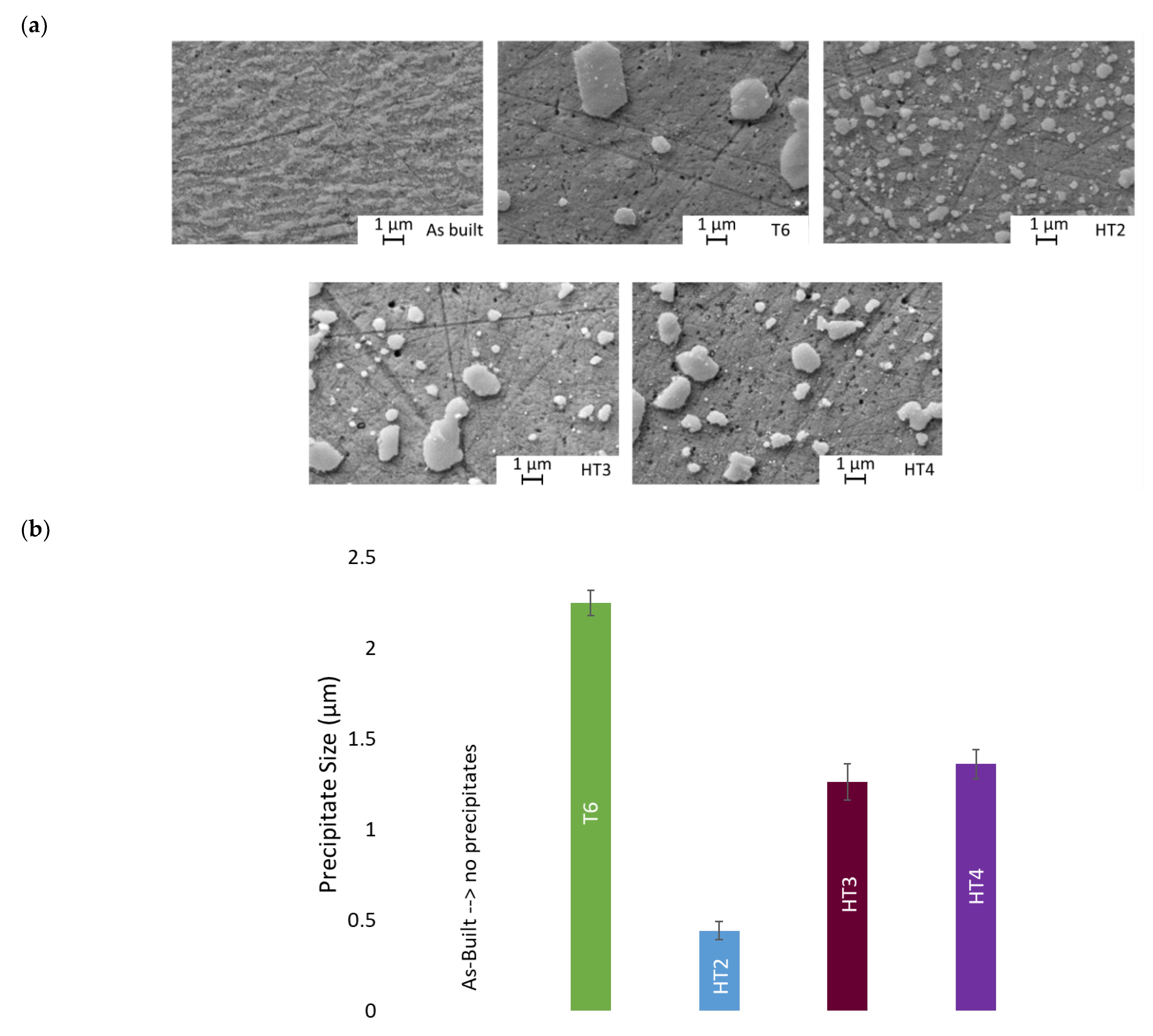
3.2. Precipitation Analysis

Figure 4a shows SEM images of as-built, T6, HT2, HT3 and HT4 state. As-built shows no precipitates, whereas T6 shows very large precipitates. The average precipitate size after T6 heat treatment is 2.25 µm. HT2 shows the smallest precipitates among all four heat treatments (mean: 0.44 µm), leading to a more homogenous distribution of the precipitates. HT3 and HT4 show larger irregular precipitates, with mean sizes of 1.26 µm and 1.36 µm, respectively (see Figure 4b). The varying mean precipitate sizes affect the precipitation hardening mechanisms, which will, in turn, define mechanical properties. The precipitates are platelet-shaped.
Distributionwise, T6, HT3 and HT4 show precipitate-rich and precipitate-poor areas with varying precipitate sizes. HT2 shows uniform precipitate sizes homogneously spread across the sample.
In terms of chemical composition (see Figure 4c), EDX analysis showed a rich Al matrix for all conditions (as-built, T6, HT2, HT3 and HT4). The precipitate compositions of T6, HT3 and HT4 were Si-rich. For HT2, the precipitations showed Al and Si with a 40:55 wt% ratio. Due to the small precipitation size and the Al-rich matrix, it is assumed that the EDX measurement included the matrix and that the precipitate compositions of all heat treatments are similar.

3.3. Vickers Hardness (HV)

Figure 5 shows the hardness of the respective heat treatments compared to the as-built condition. As expected, the as-built condition shows the highest hardness, with a value of 96.7 HV. It should be noted that the standard deviation of the as-built condition (4.01 HV) is the largest compared to the heat-treated conditions (ranging between 0.57 HV and 1.88 HV). HT2 shows the lowest hardness values, with 61.2 HV, meaning a loss of ~37% compared to the as-built condition.

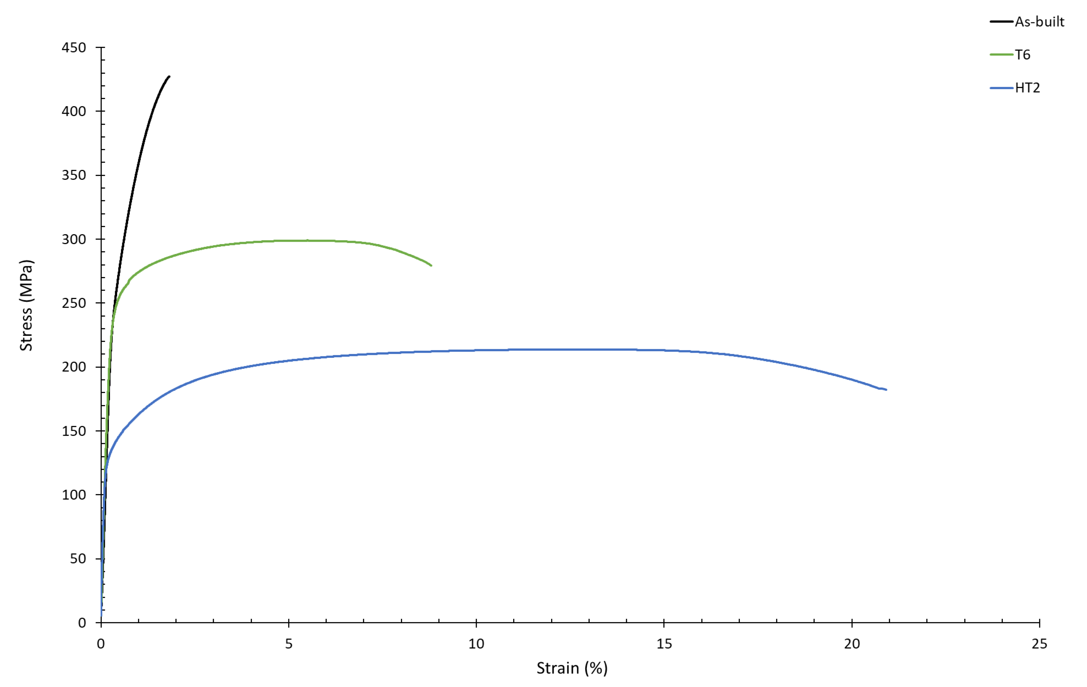
3.4. Tensile Testing

As can be seen from the precipitate size and hardness, as-built, HT2 and T6 show the extreme cases and HT3 and HT4 values lie in between. Therefore, the tensile results excluded HT3 and HT4 and focused solely on as-built, T6 and HT2. Figure 6 shows the corresponding stress–strain curves. One representative curve out of three is shown for as-built, T6 and HT2. The as-built curve indicates brittle behavior, with a maximum strain just below 2%. By heat treating the samples, ductilities of up 21% are achieved. This means an increase in factor of 10.5.

3.5. Three-Point Bending Tests

As can be seen from the precipitate size and hardness, as-built, HT2 and T6 show the extreme cases and HT3 and HT4 values lie in between. Therefore, the three-point bending results excluded HT3 and HT4 and focused solely on as-built, T6 and HT2. Figure 7 shows the force–displacement curves of the three-point bending tests. One representative curve out of three is shown for as-built, T6 and HT2. It can be clearly seen that HT2 reaches a significant increase in strain compared to the T6 and as-built state. The samples post-three-point bending are shown on the right of Figure 7. The as-built samples show little deformation, T6 shows slightly more and HT2 shows a significant increase in bending before crack initiation and ultimate failure.

3.6. Compression Testing
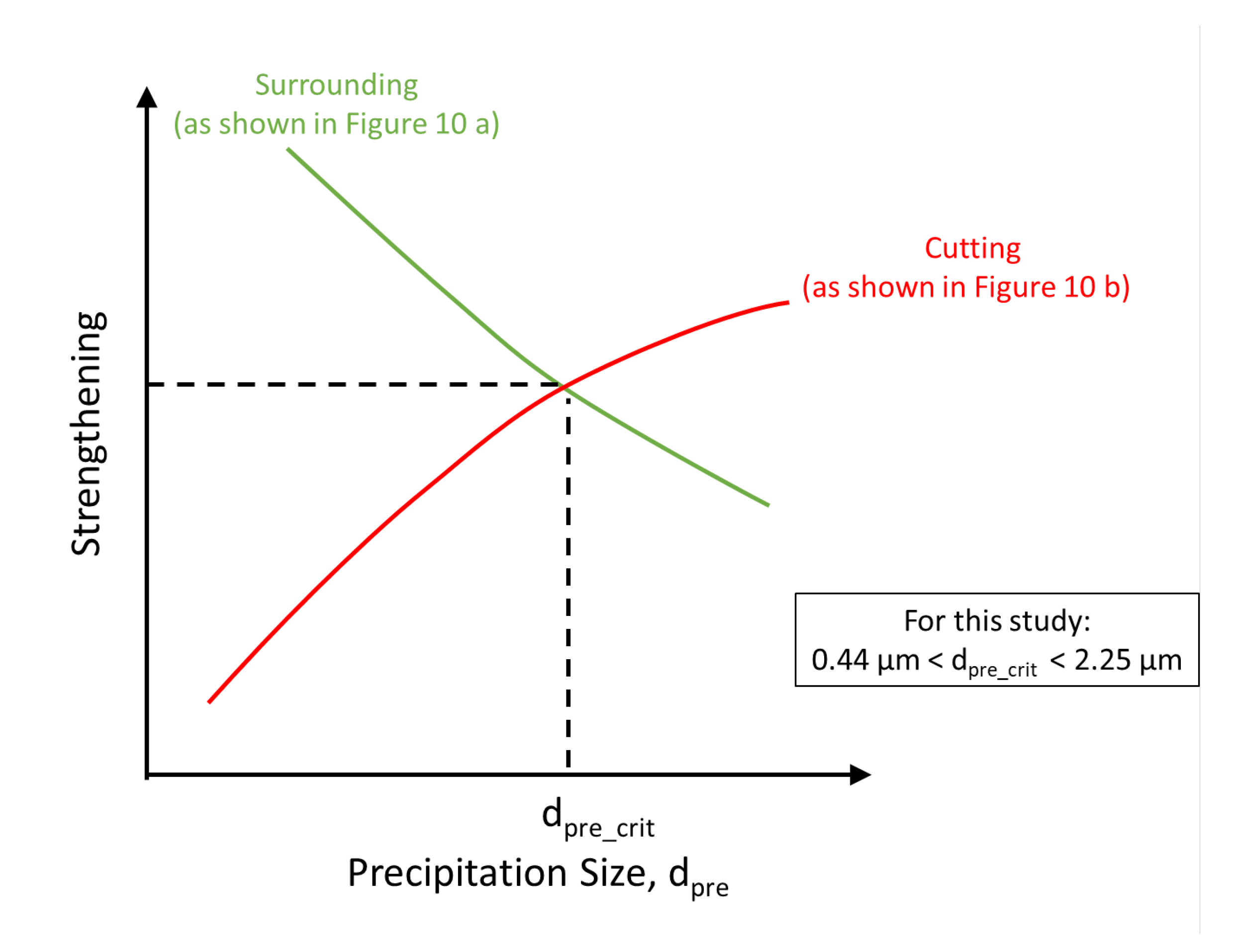
Figure 8 shows a T6 lattice structure before and after compression testing. After the compression test, the lattice structure is separated into pieces showing no signs of ductile fracture. Figure 9 shows the compression stress–strain diagrams for the T6 heat treatment, HT2, HT3 and HT4. One representative curve out of three is shown for each heat treatment. The respective samples after testing are also shown in the figure. In a preliminary study, as-built AlSi10Mg lattice structures have already been tested. Since the ductility was not sufficient (similar to that of as-built tensile ductility [34]), the tests have not been repeated and the heat treated tests were focused on in this study. T6 shows brittle fracture after limited strain. The HT2 sample withstood a maximum stress of ~27 MPa. This effective stress was calculated by relating the measured load to the outer dimensions of the lattice structure (A = 41.6 mm × 41.6 mm). Compared to the T6 heat treatment, HT2 withstood roughly double the compression stress. The HT2 strain increased from ~80% to ~90% compared to the T6 heat treatment. The images of the HT2 sample after compression testing show ductile behavior. It should be highlighted that the sample does not show failure at any of the struts. Similar observations can be made for HT3 and HT4.

4. Discussion

The relative density of the samples shown in Figure 3 shows an increase from 99.9% up to 99.97% when using heat treatments. T6 shows the highest relative density. The minimal increase of 0.07% in relative density values cannot definitively be attributed to the heat treatments of the respective samples.
The surface roughness is not affected by heat treatment. The measured values are in agreement with Liu et al. [35] and Kamarudin et al. [36]. When comparing the surface roughness of AlSi10Mg manufactured via die casting to that achieved by LPBF, the surface roughness of die casting is significantly lower (i.e., ~1.6 µm). Hence, either LPBF process parameters need to be adjusted, as shown by Mohammadi et al. [37], or abrasive postprocessing needs to be carried out to reduce surface roughness.
The EDX analysis showed Si-rich precipitates in an Al-rich matrix. When combining this result with that of the TTT diagram shown in Figure 1, the phases present in heat-treated condition are the α-matrix and either β-precipitates (Mg2Si) or Si-precipitates. This derivation agrees with the results of [38]. Considering the precipitate shape (platelet: see Figure 4a), the assumption of Mg2Si β-phase is further supported by Fiocchi et al. [38]. In order to identify whether the precipitates are Mg2Si or Si-precipitates, TEM analysis is required. Wei et al. found Mg2Si and Si-precipitates in T6 heat treated samples [39]. In the as-built state, a clear Al–Si eutectic network can be identified. Similar images in as-built conditions are found by Li et al. [17]. Similar to the results of Li et al. [17], the eutectic Al–Si network in this study dissolves after heat treatment. Further analysis of the microstructure is suggested.
The mean precipitation size allows substantial insights to the material behavior. HT2 shows the smallest precipitation size, with 0.44 µm, and T6 shows the maximum size of 2.25 µm (see Figure 4b for all mean precipitation sizes). The hardening mechanisms caused by precipitation can be achieved by cutting and/or dislocations surrounding the precipitates (schematically shown in Figure 10).
As illustrated in Figure 11, the critical precipitation size (dpre_crit) is the point of intersection of the cutting and surrounding an incoherent precipitation line. The dpre_crit reflects the threshold of switching from cutting to surrounding the precipitate [40].
T6 shows the largest precipitate size, with 2.25 µm, and a higher strength and higher hardness, tensile and bending strength, with a reduced ductility, see Figure 5, Figure 6, Figure 7 and Figure 9 and Table 3. The mechanical properties (hardness, compression, bending and tensile strength) for HT2 samples (see Figure 5, Figure 6, Figure 7 and Figure 9 and Table 3) show an increase in ductility but a significant reduction in strength. The images of the samples after compression testing showed brittle fracture for T6 and a large amount of deformation for HT2 (shown in Figure 9). This indicates an increase in plasticity in HT2 samples, which is assumed to occur by precipitation cutting processes combined with dislocation movement around the precipitates. Since the cutting of precipitates with dislocations is limited by a critical particle size (see Figure 11), this leads to the assumption that the critical precipitate size of AlSi10Mg is in the range of dpre_HT2 < dpre_crit < dpre_T6 (0.44 µm < dpre_crit < 2.25 µm).
In addition to the precipitation strengthening mechanisms, grain refinement should also be considered. The high cooling rate during LPBF [22] leads to a finer microstructure compared to conventional manufacturing technologies. Grain refinement leads to increased strength according to the Hall–Petch relation [41]. Since the amount of solid solution strengtheners is limited (see Table 1), the effect of solid solution strengthening is considered to be negligible.
The drop in strength and hardness could be explained by the increase in grain size due to the increased heat and time during the heat treatment.
As can be seen from the hardness and compression, HT3 and HT4 results lie within the bounds of T6 and HT2. Since the mean precipitate sizes are similar, this result is as expected. The as-built samples show the highest hardness compared to the heat-treated samples due to the finer grain size caused by the rapid solidification during LPBF. The grains of the heat-treated samples coarsen with increasing temperature and time. Since HT2 has the longest heat treatment duration, the largest grain size is to be expected. A reduced hardness with increased heat treatment time was also found by Fiocchi et al. [22].
Compared to Li et al., HT2 reaches a similar ductility of greater than 20% [17]. This is an increase of approximately factor 10 compared to as-built.
The difference in UTS and yield strength can also be attributed to the difference in grain size and precipitates. Compared to the as-built state, the yield strength and UTS of HT2 is reduced by more than half (see Table 3). As expected, T6 lies in between as-built and HT2.

5. Conclusion and Outlook

The aim of this study is to increase the ductility of additively manufactured AlSi10Mg by implementing adjusted heat treatments. Three heat treatments were chosen based on the literature and compared to the standard heat treatment T6 and as-built condition. Relative density, surface roughness, precipitation size, hardness, tensile, compression and three-point-bending tests were carried out. It turned out that the critical precipitation size is estimated to a range of dpre_HT2 < dpre_crit < dpre_T6 (0.44 µm < dpre_crit < 2.25 µm).
In addition to this, it was identified that the tensile ductility of AlSi10Mg can be increased up to 20%. The compression ductility reached ~90%. While HT2 significantly increases ductility, the strength of the material drops between 40–50%. This effect should be considered when choosing the mechanical application.
In future work, microstructural analysis should be carried out with regard to grain size and grain structure. The precipitates and the precipitate substructures should be analyzed with XRD and TEM. The heat treatment should be adjusted to not only increase ductility, but also to consider strength.

Author Contributions

Conceptualization, S.M.; Formal analysis, S.M., J.B. and T.D.; Funding acquisition, A.B.; Investigation, J.B.; Methodology, S.M., J.B. and A.B.; Supervision, T.D., A.B., K.-U.S. and J.H.S.; Visualization, S.M. and J.B.; Writing—original draft, S.M.; Writing—review and editing, S.M., J.B., T.D., K.-U.S. and J.H.S. All authors have read and agreed to the published version of the manuscript.

Funding

This research received no external funding.

Institutional Review Board Statement

Not applicable.

Informed Consent Statement

Not applicable.

Data Availability Statement

The raw/processed data required to reproduce these findings cannot be shared at this time, as the data also form part of an ongoing study.

Conflicts of Interest

The authors declare no conflict of interest.

References

  1. Aboulkhair, N.T.; Everitt, N.M.; Ashcroft, I.; Tuck, C. Reducing porosity in AlSi10Mg parts processed by selective laser melting. Addit. Manuf. 2014, 1–4, 77–86. [Google Scholar] [CrossRef]
  2. Cabrini, M.; Lorenzi, S.; Pastore, T.; Testa, C.; Manfredi, D.; Cattano, G.; Calignano, F. Corrosion resistance in chloride solution of the AlSi10Mg alloy obtained by means of LPBF. Surf. Interface Anal. 2019, 51, 1159–1164. [Google Scholar] [CrossRef]
  3. Louvis, E.; Fox, P.; Sutcliffe, C.J. Selective laser melting of aluminium components. J. Mater. Processing Technol. 2011, 211, 275–284. [Google Scholar] [CrossRef]
  4. Buchbinder, D.; Wissenbach, K.; Meiners, W. Rapid manufacturing of aluminium parts for serial production via selective laser melting (SLM). In Proceedings of the 11th International Conference on Aluminium Alloys, Aachen, Germany, 22–26 September 2008; pp. 2394–2400. [Google Scholar]
  5. Lefebvre, W.; Rose, G.; Delroisse, P.; Baustert, E.; Cuvilly, F.; Simar, A. Nanoscale periodic gradients generated by laser powder bed fusion of an AlSi10Mg alloy. Mater. Des. 2021, 197, 109264. [Google Scholar] [CrossRef]
  6. Kempen, K.; Thijs, L.; van Humbeeck, J.; Kruth, J.-P. Mechanical Properties of AlSi10Mg Produced by Selective Laser Melting. Phys. Procedia 2012, 39, 439–446. [Google Scholar] [CrossRef] [Green Version]
  7. Alghamdi, F.; Haghshenas, M. Microstructural and small-scale characterization of additive manufactured AlSi10Mg alloy. SN Appl. Sci. 2019, 255, 22. [Google Scholar] [CrossRef] [Green Version]
  8. Osuch, P.; Walkowicz, M.; Knych, T.; Dymek, S. Impact of the Direct Ageing Procedure on the Age Hardening Response of Al-Mg-Si 6101 Alloy. Materials 2018, 11, 1239. [Google Scholar] [CrossRef] [Green Version]
  9. Jordovic, B.; Nedeljkovic, B.; Mitrovic, N.; Zivanic, J.; Maricic, A. Effect of heat treatment on structural changes in metastable AlSi10mg alloy. J. Min. Metall. B Metall. 2014, 50, 133–137. [Google Scholar] [CrossRef] [Green Version]
  10. Tang, M.; Pistorius, P.C. Fatigue life prediction for AlSi10Mg components produced by selective laser melting. Int. J. Fatigue 2019, 125, 479–490. [Google Scholar] [CrossRef]
  11. Siddique, S.; Imran, M.; Wycisk, E.; Emmelmann, C.; Walther, F. Influence of process-induced microstructure and imperfections on mechanical properties of AlSi12 processed by selective laser melting. J. Mater. Processing Technol. 2015, 221, 205–213. [Google Scholar] [CrossRef]
  12. Ostermann, F. Anwendungstechnologie Aluminium; Springer: Berlin/Heidelberg, Germany, 2014; ISBN 978-3-662-43806-0. [Google Scholar]
  13. Aboulkhair, N.; Maskery, I.; Tuck, C.; Ashcroft, I.; Everitt, N. The microstructure and mechanical properties of selectively laser melted AlSi10Mg: The effect of a conventional T6-like heat treatment. Mater. Sci. Eng. A 2016, 667, 46. [Google Scholar] [CrossRef]
  14. Maskery, I.; Aboulkhair, N.T.; Aremu, A.O.; Tuck, C.J.; Ashcroft, I.A. Compressive failure modes and energy absorption in additively manufactured double gyroid lattices. Addit. Manuf. 2017, 16, 24–29. [Google Scholar] [CrossRef]
  15. Maskery, I.; Aboulkhair, N.T.; Aremu, A.O.; Tuck, C.J.; Ashcroft, I.A.; Wildman, R.D.; Hague, R.J.M. A mechanical property evaluation of graded density Al-Si10-Mg lattice structures manufactured by selective laser melting. Mater. Sci. Eng. A 2016, 670, 264–274. [Google Scholar] [CrossRef] [Green Version]
  16. Li, Z.H.; Nie, Y.F.; Liu, B.; Kuai, Z.Z.; Zhao, M.; Liu, F. Mechanical properties of AlSi10Mg lattice structures fabricated by selective laser melting. Mater. Des. 2020, 192, 108709. [Google Scholar] [CrossRef]
  17. Li, W.; Li, S.; Liu, J.; Zhang, A.; Zhou, Y.; Wei, Q.; Yan, C.; Shi, Y. Effect of heat treatment on AlSi10Mg alloy fabricated by selective laser melting: Microstructure evolution, mechanical properties and fracture mechanism. Mater. Sci. Eng. A 2016, 663, 116–125. [Google Scholar] [CrossRef]
  18. Kempen, K.; Thijs, L.; van Humbeeck, J.; Kruth, J.-P. Processing AlSi10Mg by selective laser melting: Parameter optimisation and material characterisation. Mater. Sci. Technol. 2015, 31, 917–923. [Google Scholar] [CrossRef]
  19. Dadbakhsh, S.; Hao, L.; Jerrard, P.G.E.; Zhang, D.Z. Experimental investigation on selective laser melting behaviour and processing windows of in situ reacted Al/Fe2O3 powder mixture. Powder Technol. 2012, 231, 112–121. [Google Scholar] [CrossRef]
  20. Buchbinder, D.; Schleifenbaum, H.; Heidrich, S.; Meiners, W.; Bültmann, J. High Power Selective Laser Melting (HP SLM) of Aluminum Parts. Phys. Procedia 2011, 12, 271–278. [Google Scholar] [CrossRef]
  21. Olakanmi, E.O. Selective laser sintering/melting (SLS/SLM) of pure Al, Al–Mg, and Al–Si powders: Effect of processing conditions and powder properties. J. Mater. Processing Technol. 2013, 213, 1387–1405. [Google Scholar] [CrossRef]
  22. Fiocchi, J.; Tuissi, A.; Biffi, C.A. Heat treatment of aluminium alloys produced by laser powder bed fusion: A review. Mater. Des. 2021, 204, 109651. [Google Scholar] [CrossRef]
  23. Girelli, L.; Tocci, M.; Gelfi, M.; Pola, A. Study of heat treatment parameters for additively manufactured AlSi10Mg in comparison with corresponding cast alloy. Mater. Sci. Eng. A 2019, 739, 317–328. [Google Scholar] [CrossRef]
  24. Qiu, C.; Yue, S.; Adkins, N.J.E.; Ward, M.; Hassanin, H.; Lee, P.D.; Withers, P.J.; Attallah, M.M. Influence of processing conditions on strut structure and compressive properties of cellular lattice structures fabricated by selective laser melting. Mater. Sci. Eng. A 2015, 628, 188–197. [Google Scholar] [CrossRef]
  25. DIN EN 1706:2020-06; Aluminium und Aluminiumlegierungen-Gussstücke-Chemische Zusammensetzung und mechanische Eigenschaften; Deutsche Fassung EN_1706:2020. Beuth Verlag GmbH: Berlin, Germany, 2020.
  26. Rehme, O. Cellular Design for Laser Freeform Fabrication, 1st ed.; Cuvillier Verlag: Göttingen, Germany, 2010; ISBN 9783736932739. [Google Scholar]
  27. Bühring, J.; Aghdam, N.J.; Mekala, N.R.; Schröder, K.-U. Numerical investigations about the use of lattice structures in energy absorbing systems. Proc. Appl. Math. Mech. 2019, 19, e201900278. [Google Scholar] [CrossRef]
  28. Brandl, E.; Heckenberger, U.; Holzinger, V.; Buchbinder, D. Additive manufactured AlSi10Mg samples using Selective Laser Melting (SLM): Microstructure, high cycle fatigue, and fracture behavior. Mater. Des. 2012, 34, 159–169. [Google Scholar] [CrossRef]
  29. Aboulkhair, N.T.; Tuck, C.; Ashcroft, I.; Maskery, I.; Everitt, N.M. On the Precipitation Hardening of Selective Laser Melted AlSi10Mg. Metall. Mat. Trans. A 2015, 46, 3337–3341. [Google Scholar] [CrossRef]
  30. Tiryakioğlu, M. The effect of solution treatment and artificial aging on the work hardening characteristics of a cast Al–7%Si–0.6%Mg alloy. Mater. Sci. Eng. A 2006, 427, 154–159. [Google Scholar] [CrossRef]
  31. Ogris, E.; Wahlen, A.; Lüchinger, H.; Uggowitzer, P.J. On the silicon spheroidization in Al–Si alloys. J. Light Met. 2002, 2, 263–269. [Google Scholar] [CrossRef]
  32. Zhang, D.L.; Zheng, L.H.; StJohn, D.H. Effect of a short solution treatment time on microstructure and mechanical properties of modified Al–7wt.%Si–0.3wt.%Mg alloy. J. Light Met. 2002, 2, 27–36. [Google Scholar] [CrossRef]
  33. DIN 50134:2008-10; Prüfung von Metallischen Werkstoffen- Druckversuch an Metallischen Zellularen Werkstoffen. Beuth Verlag GmbH: Berlin, Germany, 2008.
  34. Sert, E.; Hitzler, L.; Hafenstein, S.; Merkel, M.; Werner, E.; Öchsner, A. Tensile and compressive behaviour of additively manufactured AlSi10Mg samples. Prog. Addit. Manuf. 2020, 5, 305–313. [Google Scholar] [CrossRef] [Green Version]
  35. Liu, B.; Li, B.-Q.; Li, Z. Selective laser remelting of an additive layer manufacturing process on AlSi10Mg. Results Phys. 2019, 12, 982–988. [Google Scholar] [CrossRef]
  36. Kamarudin, K.; Wahab, M.S.; Shayfull, Z.; Ahmed, A.; Raus, A.A. Dimensional Accuracy and Surface Roughness Analysis for AlSi10Mg Produced by Selective Laser Melting (SLM). MATEC Web Conf. 2016, 78, 1077. [Google Scholar] [CrossRef] [Green Version]
  37. Mohammadi, M.; Asgari, H. Achieving low surface roughness AlSi10Mg_200C parts using direct metal laser sintering. Addit. Manuf. 2018, 20, 23–32. [Google Scholar] [CrossRef]
  38. Lam, L.P.; Zhang, D.Q.; Liu, Z.H.; Chua, C.K. Phase analysis and microstructure characterisation of AlSi10Mg parts produced by Selective Laser Melting. Virtual Phys. Prototyp. 2015, 10, 207–215. [Google Scholar] [CrossRef]
  39. Wei, P.; Chen, Z.; Zhang, S.; Fang, X.; Lu, B.; Zhang, L.; Wei, Z. Effect of T6 heat treatment on the surface tribological and corrosion properties of AlSi10Mg samples produced by selective laser melting. Mater. Charact. 2021, 171, 110769. [Google Scholar] [CrossRef]
  40. Bergmann, W. Werkstofftechnik, 7th ed.; Hanser: München, Germany, 2013; ISBN 9783446435810. [Google Scholar]
  41. David, A.P.; Kenneth, E.E. Phase Transformations in Metals and Alloys (Revised Reprint); CRC Press: Boca Raton, FL, USA, 2009; ISBN 9780429112256. [Google Scholar]
Figure 1. Schematic phase and TTT diagram of Al–Si alloys, reproduced and adjusted from [7,8,9].
Metals 12 01311 g001
Figure 2. (a) Substrate plate (250 mm × 250 mm) with 12 lattice structures, 17 tensile samples, 17 cubes; (b) images of build job with 12 lattice structures, 17 cylinders, 17 cubes and 15 bending samples.
Metals 12 01311 g002
Figure 3. Images of cross-section with relative density measurement.
Metals 12 01311 g003
Figure 4. (a) SEM images of as-built, T6, HT2, HT3 and HT4 specimens for precipitation analysis. As-built shows no precipitates,T6 shows the largest precipitates, followed by HT4, HT3 and HT2; (b) mean precipitation size and standard deviation for all sample conditions; (c) EDX analysis of matrix and precipitate compositions.
Metals 12 01311 g004aMetals 12 01311 g004b
Figure 5. Vickers hardness of as-built, T6, HT2, HT3 and HT4. As-built shows the highest hardness, HT2 shows the lowest hardness. Values shown are a mean out of three measurements.
Metals 12 01311 g005
Figure 6. Tensile stress–strain diagramm for as-built, T6 and HT2. As-built LPBF condition showed the lowest strain, HT2 showed the highest tensile strain.
Metals 12 01311 g006
Figure 7. Force–displacement curves of the 3-point bending tests of as-built, T6 and HT2. The respective samples are shown on the right.
Metals 12 01311 g007
Figure 8. Lattice structure (T6) before (left) and after compression test (right).
Metals 12 01311 g008
Figure 9. Compressive stress–strain diagramm for T6, HT2, HT3 and HT4. T6 showed the lowest strain, HT2, HT4 and HT4 showed the highest compressive strain.
Metals 12 01311 g009
Figure 10. Precipitation hardening mechanisms: (a) dislocations surround precipitates; (b) dislocations cut precipitates (if below critical precipitation size).
Metals 12 01311 g010
Figure 11. Schematic illustration of the influence of precipitate sizes on cutting or circulating a precipitation in the matrix material, reproduced and adjusted from [40].
Metals 12 01311 g011
Table 1. Nominal composition of AlSi10Mg, Data from [25].
ElementAlSiMgFeCuTiMnNiZnPbSn
Wt.%Bal. 9–110.25–0.45<0.55<0.05<0.15<0.45<0.05<0.1<0.050.05
Table 2. Investigated ASI10Mg heat treatments Data from [13,17].
T6HT2HT3HT4
  • ▪ Solution treatment: 525 ℃ for 4.5 h
  • ▪ Water quenching
  • ▪ Aging: 165 ℃ for 7 h
  • ▪ Solution treatment: 450 ℃ for 2 h
  • ▪ Water quenching
  • ▪ Aging: 180 ℃ for 12 h
  • ▪ Solution treatment: 500 ℃ for 2 h
  • ▪ Water quenching
  • ▪ Aging: 300 ℃ for 0.5 h
  • ▪ Solution treatment: 500 ℃ for 2 h
  • ▪ Water quenching
  • ▪ Aging: 180 ℃ for 12 h
Table 3. Overview of mechanical properties in this study for as-built, T6 and HT2.
As-builtT6HT2
Hardness (HV)~97~90~61
UTS (MPa)~430~290~205
Yield Strength (MPa)~260~180~100
Tensile Elongation (%)~2~9~21
Compressive Strength (MPa)-~14~27
Compressive Elongation (%)-~80~91
Bending Strength (MPa)~80~68~55
Precipitation size (µm)-~2.25~0.44
Publisher’s Note: MDPI stays neutral with regard to jurisdictional claims in published maps and institutional affiliations.

