
In-Process Fingerprints of Dissimilar Titanium Alloy Diffusion Bonded Layers from Hole Drilling Force Data


Abstract
:1. Introduction
2. Materials and Methods
2.1. FAST Sample Manufacture
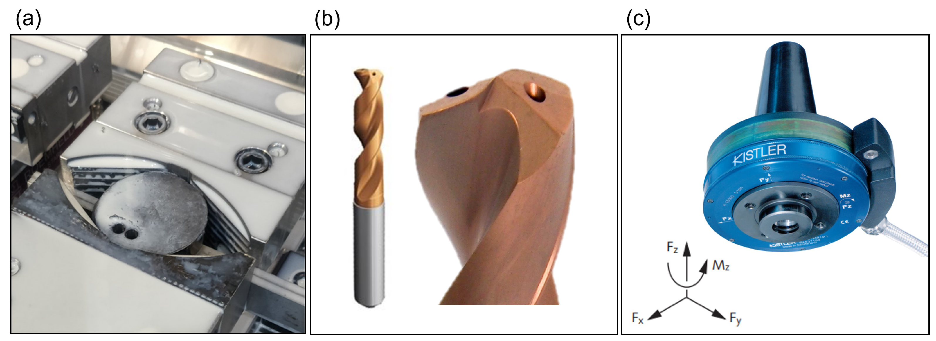
2.2. Machine and Tooling
2.3. Measurement and Analysis
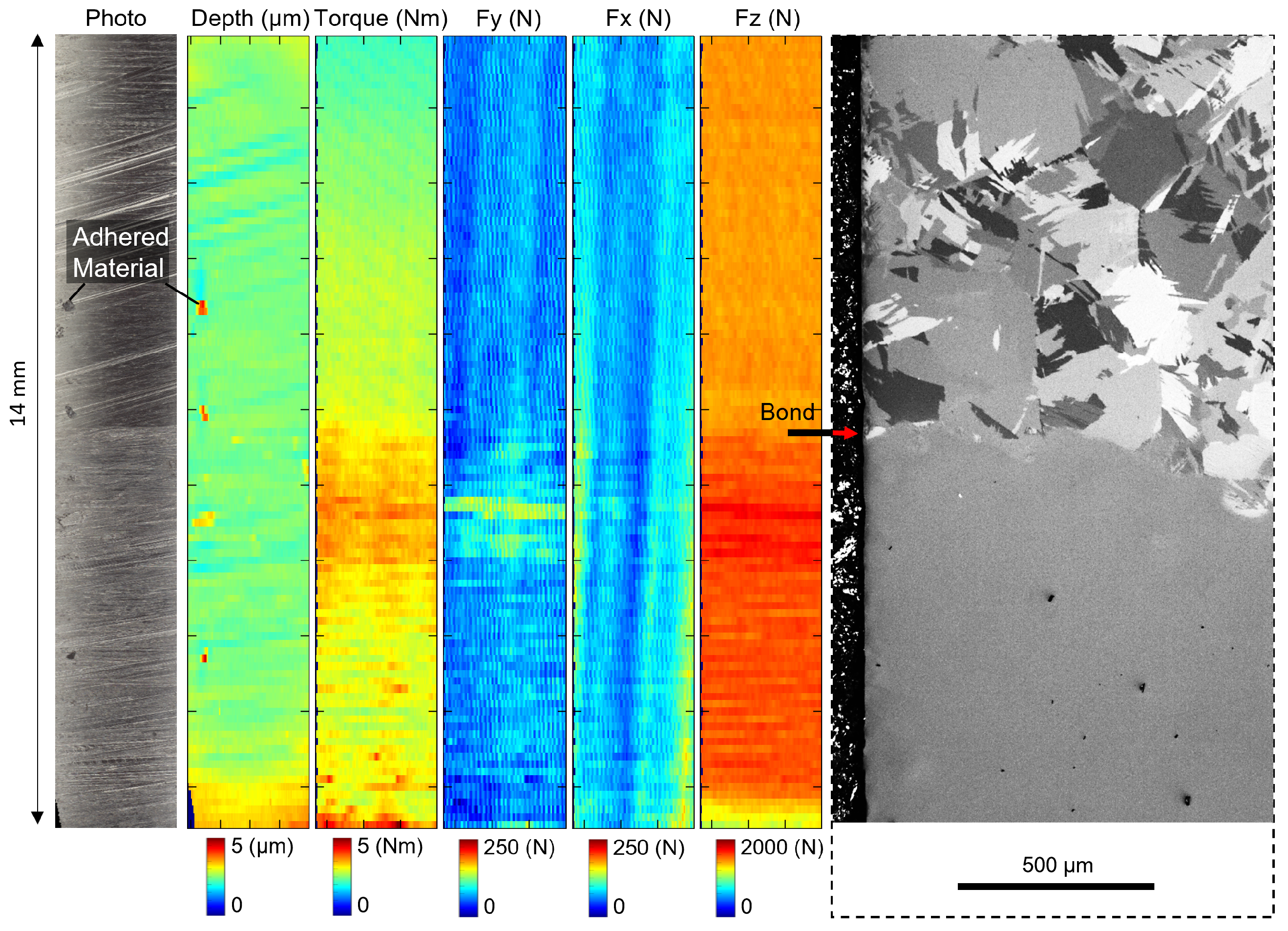
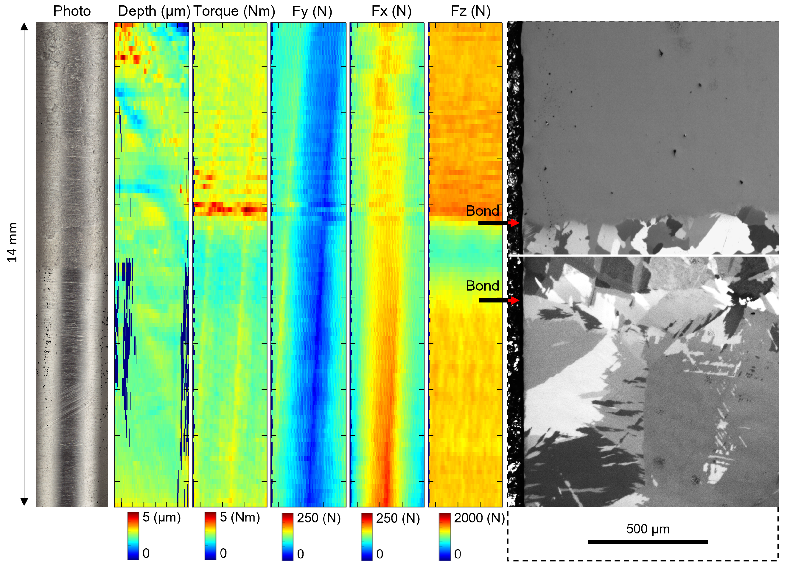
2.4. Force Feedback Fingerprint Reconstruction
3. Results
4. Discussion
5. Conclusions
- It is possible to drill multi-material workpieces without substantial surface or subsurface damage or hole quality issues at bond locations.
- When many alloys are drilled in a single workpiece the operation has poorer stability which can reduce hole quality.
- As in turning there is a directionality effect between each alloy pair, however for drilling there is is also a more significant effect influenced by the number of alloys drilled in a workpiece and therefore stability.
- Smart drilling strategies can be implemented from the results presented in this work. It is better to machine alloys at the very end of the machining operation and the machining of CP should be placed as closer to the contact point to avoid chemical contamination and that similar chemistry alloy compositions are easier to machine.
- Force feedback fingerprinting is effective for investigating aspects of multialloy machinability and can be used to idenitfy the location of bonds within multi alloys.
Author Contributions
Funding
Data Availability Statement
Acknowledgments
Conflicts of Interest
References
- Metallurgy, P. Titanium: Physical Metallurgy, Processing, and Applications; Froes, FHe., ASM International: Novelty, OH, USA, 2015. [Google Scholar]
- Joshi, V.A. Titanium Alloys; CRC Press: Boca Raton, FL, USA, 2006. [Google Scholar] [CrossRef]
- Fernández, D.S.; Wynne, B.; Crawforth, P.; Fox, K.; Jackson, M. The effect of forging texture and machining parameters on the fatigue performance of titanium alloy disc components. Int. J. Fatigue 2021, 142, 105949. [Google Scholar] [CrossRef]
- Lütjering, G. Influence of processing on microstructure and mechanical properties of (α + β) titanium alloys. Mater. Sci. Eng. A 1998, 243, 32–45. [Google Scholar] [CrossRef]
- Cotton, J.D.; Briggs, R.D.; Boyer, R.R.; Tamirisakandala, S.; Russo, P.; Shchetnikov, N.; Fanning, J.C. State of the Art in Beta Titanium Alloys for Airframe Applications. Jom 2015, 67, 1281–1303. [Google Scholar] [CrossRef]
- Levano Blanch, O.; Lunt, D.; Baxter, G.J.; Jackson, M. Deformation Behaviour of a FAST Diffusion Bond Processed from Dissimilar Titanium Alloy Powders. Metall. Mater. Trans. A 2021, 52, 3064–3082. [Google Scholar] [CrossRef]
- Suarez, M.; Fernandez, A.; Menendez, J.; Torrecillas, R.; Kessel, J.H.U.; Kirchner, R.; Kessel, T. Challenges and Opportunities for Spark Plasma Sintering: A Key Technology for a New Generation of Materials. In Sintering Applications; IntechOpen: London, UK, 2013. [Google Scholar] [CrossRef]
- Brinksmeier, E. Prediction of Tool Fracture in Drilling. CIRP Ann.-Manuf. Technol. 1990, 39, 97–100. [Google Scholar] [CrossRef]
- Patil, S.; Kekade, S.; Phapale, K.; Jadhav, S.; Powar, A.; Supare, A.; Singh, R. Effect of α and β Phase Volume Fraction on Machining Characteristics of Titanium Alloy Ti6Al4V. Procedia Manuf. 2016, 6, 63–70. [Google Scholar] [CrossRef]
- Arrazola, P.J.; Garay, A.; Iriarte, L.M.; Armendia, M.; Marya, S.; Le Maître, F. Machinability of titanium alloys (Ti6Al4V and Ti555.3). J. Mater. Process. Technol. 2009, 209, 2223–2230. [Google Scholar] [CrossRef]
- Graves, A.; Norgren, S.; Crawforth, P.; Jackson, M. A novel method for investigating drilling machinability of titanium alloys using velocity force maps. Adv. Ind. Manuf. Eng. 2021, 2, 100043. [Google Scholar] [CrossRef]
- Xu, J.; El Mansori, M. Experimental study on drilling mechanisms and strategies of hybrid CFRP/Ti stacks. Compos. Struct. 2016, 157, 461–482. [Google Scholar] [CrossRef]
- Uthayakumar, M.; Prabhaharan, G.; Aravindan, S.; Sivaprasad, J. Study on aluminum alloy piston reinforced with cast iron insert. Int. J. Mater. Sci. 2008, 3, 1–10. [Google Scholar]
- Uthayakumar, M.; Prabhakaran, G.; Aravindan, S.; Sivaprasad, J. Influence of cutting force on bimetallic piston machining by a cubic boron nitride (CBN) tool. Mater. Manuf. Process. 2012, 27, 1078–1083. [Google Scholar] [CrossRef]
- Saligheh, A.; Hajialimohammadi, A.; Abedini, V. Cutting Forces and Tool Wear Investigation for Face Milling of Bimetallic Composite Parts Made of Aluminum and Cast Iron Alloys. Int. J. Eng. 2020, 33, 1142–1148. [Google Scholar]
- Manikandan, G.; Uthayakumar, M.; Aravindan, S. Machining and simulation studies of bimetallic pistons. Int. J. Adv. Manuf. Technol. 2013, 66, 711–720. [Google Scholar] [CrossRef]
- Levano Blanch, O.; Suárez Fernández, D.; Graves, A.; Jackson, M. MulTi-FAST: A Machinability Assessment of Functionally Graded Titanium Billets Produced from Multiple Alloy Powders. Materials 2022, 15, 3237. [Google Scholar] [CrossRef] [PubMed]
- Suárez Fernández, D.; Jackson, M.; Crawforth, P.; Fox, K.; Wynne, B. Using machining force feedback to quantify grain size in beta titanium. Materialia 2020, 13, 100856. [Google Scholar] [CrossRef]
- Naisson, P.; Rech, J.; Paris, H. Analytical modeling of thrust force and torque in drilling. Proc. Inst. Mech. Eng. Part B J. Eng. Manuf. 2013, 227, 1430–1441. [Google Scholar] [CrossRef]
- Suárez Fernández, D.; Wynne, B.; Crawforth, P.; Jackson, M. Titanium alloy microstructure fingerprint plots from in-process machining. Mater. Sci. Eng. A 2021, 811, 141074. [Google Scholar] [CrossRef]
- Mills, B. Machinability of Engineering Materials; Springer Science & Business Media: Berlin/Heidelberg, Germany, 2012. [Google Scholar]
- Pope, J.J.; Calvert, E.L.; Weston, N.S.; Jackson, M. FAST-DB: A novel solid-state approach for diffusion bonding dissimilar titanium alloy powders for next generation critical components. J. Mater. Process. Technol. 2019, 269, 200–207. [Google Scholar] [CrossRef]
- Cox, A.; Herbert, S.; Villain-Chastre, J.P.; Turner, S.; Jackson, M. The effect of machining and induced surface deformation on the fatigue performance of a high strength metastable β titanium alloy. Int. J. Fatigue 2019, 124, 26–33. [Google Scholar] [CrossRef]
- Graves, A.; Norgren, S.; Crawforth, P.; Jackson, M. Surface roughness response to drilling of Ti-5Al-5Mo-5V-3Cr using Ti-Al-N PVD coated and uncoated WC/Co tools. Procedia CIRP 2020, 87, 170–175. [Google Scholar] [CrossRef]


| Alloy Name | Nominal Composition (wt.%) |
|---|---|
| Ti-CP | bal.Ti |
| Ti-3-2.5 | 3Al, 2.5V, bal. Ti |
| Ti-64 | 6Al, 4V, bal. Ti |
| Ti-6242 | 6Al, 4Zr 2Mo 2Sn bal Ti |
| Ti-5553 | 5 Al, 5V, 5Mo, 3Cr, bal. Ti |
| Ti Beta C | 3Al, 8V, 6Cr, 4Mo, 4Zr, bal. Ti |
| Plate No. | Order of Titanium Alloys in Multi-Material Billets | Blind (Y/N) |
|---|---|---|
| 1 | Ti-64, Beta C | N |
| 2 | Beta C, Ti-64, Ti-CP | N |
| 3 | Ti-CP, Ti-6242, Ti-64, Ti-5553, BetaC | N |
| 4 | Ti-64, Ti-CP, Beta C | Y |
| 5 | Ti-3-2.5, Ti-6242, Ti-CP, Ti-5553, Beta C, Ti-64 | Y |
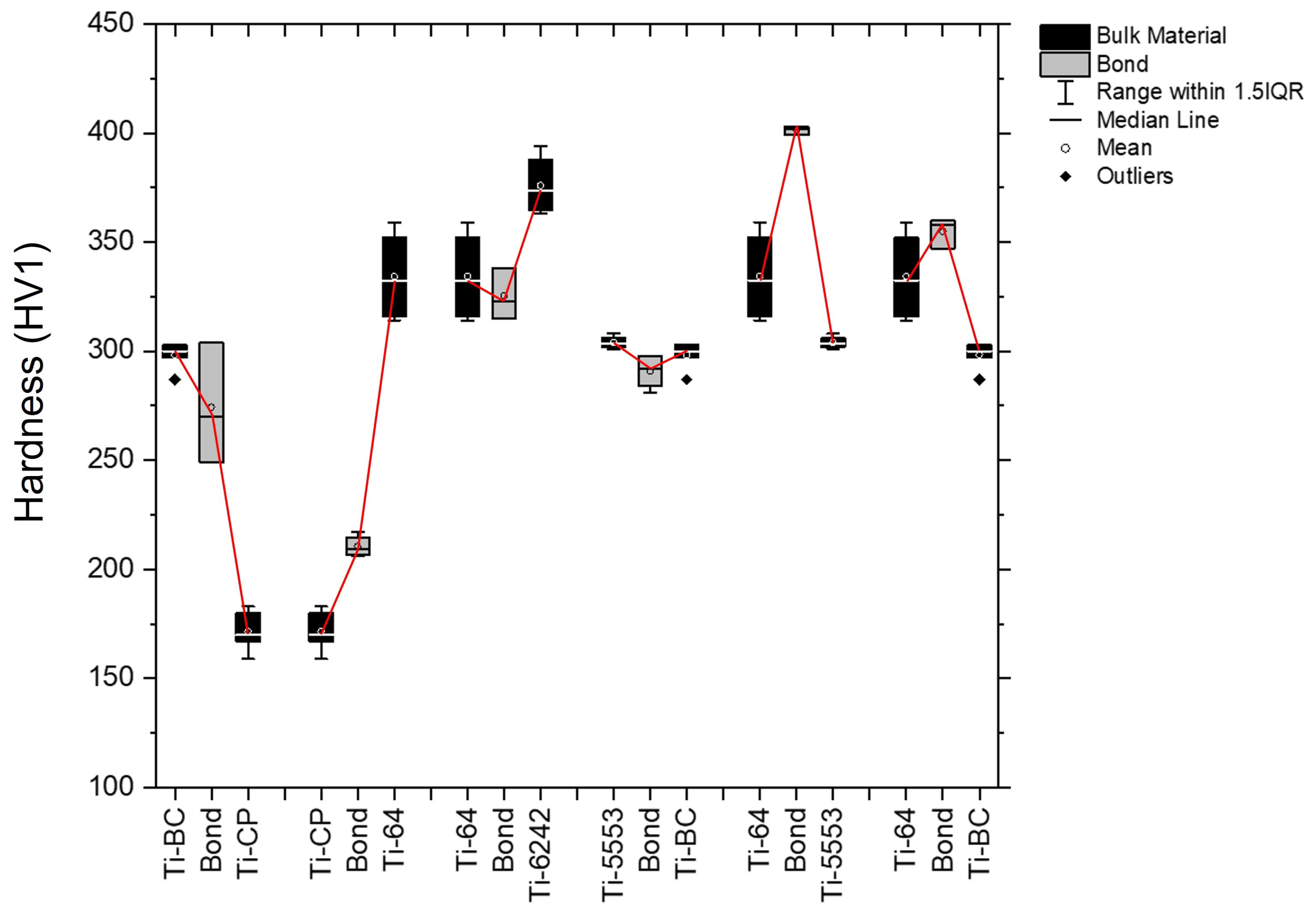
| Alloy Name | Vickers Hardness (HV1) |
|---|---|
| Ti-CP | 175 (±10) |
| Ti-3-2.5 | 278 (±17) |
| Ti-64 | 330 (±20) |
| Ti-6242 | 375 (±15) |
| Ti-5553 | 305 (±3) |
| Beta C | 300 (±3) |
Publisher’s Note: MDPI stays neutral with regard to jurisdictional claims in published maps and institutional affiliations. |
© 2022 by the authors. Licensee MDPI, Basel, Switzerland. This article is an open access article distributed under the terms and conditions of the Creative Commons Attribution (CC BY) license (https://creativecommons.org/licenses/by/4.0/).
Share and Cite
Graves, A.; Blanch, O.L.; Fernández, D.S.; Jackson, M. In-Process Fingerprints of Dissimilar Titanium Alloy Diffusion Bonded Layers from Hole Drilling Force Data. Metals 2022, 12, 1353. https://doi.org/10.3390/met12081353
Graves A, Blanch OL, Fernández DS, Jackson M. In-Process Fingerprints of Dissimilar Titanium Alloy Diffusion Bonded Layers from Hole Drilling Force Data. Metals. 2022; 12(8):1353. https://doi.org/10.3390/met12081353
Chicago/Turabian StyleGraves, Alex, Oliver Levano Blanch, Daniel Suárez Fernández, and Martin Jackson. 2022. "In-Process Fingerprints of Dissimilar Titanium Alloy Diffusion Bonded Layers from Hole Drilling Force Data" Metals 12, no. 8: 1353. https://doi.org/10.3390/met12081353