Article

Pure-Bend and Over-Bend Straightening Theory for In-Plane Curved Beams with Symmetrical Section and Straightening Mechanism Analysis

1
School of Mechanical and Energy Engineering, NingboTech University, Ningbo 315100, China
2
Key Laboratory of Advanced Forging & Stamping Technology and Science of Ministry of Education of China, Yanshan University, Qinhuangdao 066004, China
3
School of Information and Intelligent Engineering, Zhejiang Wanli University, Ningbo 315175, China
4
Ningbo Vorias Machinery Technology Co., Ltd., Ningbo 315100, China
*
Author to whom correspondence should be addressed.
Metals 2022, 12(8), 1362; https://doi.org/10.3390/met12081362
Submission received: 23 July 2022 / Revised: 13 August 2022 / Accepted: 15 August 2022 / Published: 16 August 2022
(This article belongs to the Special Issue Plastic Forming, Microstructure, and Property Optimization of Metals)

Abstract

:
Straightening is an important process in the production and application of shafts, tubes, and various profiles. According to the springback theory of small curvature plane bending, the pure bending process and springback of in-plane curved beam with symmetrical section were analyzed, and the over-bend straightening theory was established. Based on this, the straightening mechanism of the existing over-bend straightening process was revealed; that is, a zigzag straightening moment was applied in the three-point multi-step straightening process to approximate the smooth curve of theoretical moment, while the multi-point one-time straightening technology was to discretize the theoretical curve using the broken line, so both of them needed a load correction coefficient to compensate the error between the actual load and theoretical calculation. In order to realize the complete loading of theoretical curve, a new technology of three-roll continuous straightening was further proposed and the experimental equipment for shafts and tubes was built. In order to match the characteristics of a pipe section, an accurate moment calculation equation was established. Three-roll continuous straightening experiments of the tube showed that the straightness of the straightened workpiece could be controlled within 1.5‰, which meets the standard requirements. Therefore, it is suggested that the over-bend straightening theory can predict the load required for straightening in-plane curved parts with any symmetrical cross-section, and the three-roller continuous straightening process is an efficient and highly accurate straightening technique.

1. Introduction

Shafts, tubes, and various profiles inevitably deform during heat treatment, transportation, and application. If straightening is not performed, it affects subsequent processing and product performance. Therefore, the straightening process is widely used in metal processing, machinery manufacturing, and instrument production. Moreover, straightening not only affects the macroscopic shape and size of the workpiece but also changes the microstructure and internal stress distribution of the material.
For in-plane curved parts, the common straightening methods are three-point press straightening and parallel roll straightening, as shown in Figure 1. According to their forming process, the roll straightening consists of multiple three-point press straightening; that is, three-point straightening is the basis. The key of the pressure straightening process is to determine the straightening force’ that is, a reasonable load can make the workpiece straight after the springback, while the section is not severely deformed. This load is related to the initial deflection [1], cross-sectional shape [2], and material properties [3,4] of the workpiece.
In order to predict the straightening load, the elastic-plastic deformation process of shaft and tube parts was fully analyzed to establish an accurate mathematical model. Focus on press straightening, Zhao et al. [5,6] proposed the multi-step three-point bending and the multi-point bending one-off straightening process for LSAW pipes and established the mechanical model and press straightening control strategy, respectively. Li et al. [7] established and verified a mathematical load-deflection model of press straightening process for shafts; Pei et al. [8] proposed the straightening prediction models for the D-type cross-section shaft to calculate the straightening reverse curvature analytically; and Song [9] gave the load-deflection model for the T-section rail press straightening process under lateral loads.
On the other hand, for multi-roll straightening, Yu et al. [3] analyzed the deformation of bar in the two-roller straightening process, established the equation of residual curvature and the unified equation of residual curvature, and then studied the springback problems of multiple reciprocating bending based on different hardening models [4]. Yin et al. [10] and Liu et al. [11] investigated the residual stress and stress-inheriting behavior of H-beam in multiple roll systems. Moreover, Huang et al. [12,13] analyzed the process of continuous and synchronous calibration of roundness and straightness by three rollers and established a mechanical model of axial and circumferential bidirectional deformation. Guan et al. [14] analyzed the sectional stress-inheriting mode during repeated elastic-plastic bending and its effect on the section’s bending properties.
In addition, numerical calculation and numerical simulation based on iterative ideas combined with experiments are also important means to analyze the straightening process. Based on the iterative method, Ma et al. [15,16] proposed a compensation mechanism to control the springback in the free-bending and stretch-bending processes, and Lu et al. [17] solved the straightening stroke in the pressure straightening process. Meanwhile, for the same pressure straightening problem, Song [18] used the finite element method to establish a load-deflection model. Nassiraei et al. [19,20] investigated the local joint flexibility of various T/Y-joints mainly by numerical simulation. In contrast, numerical simulation has more obvious advantages in analyzing complex straightening processes, such as the three-roller continuous and synchronous adjusting straightness and roundness process [21], reciprocating bending straightening process [22], multi-roller straightening process [23,24], and heavy rail straightening process [25].
The studies conducted so far have shown that both theoretical and numerical simulations are difficult to establish a general analysis model to guide the straightening process. Therefore, this paper intended to establish an analytical model of over-bend straightening which can be applied to in-plane curved workpieces with arbitrary symmetrical sections. Then, the straightening mechanism of the existing technology was analyzed, and a new technology was proposed. Based on the general model, the process of straightening a tube with new technology was analyzed and verified by physical experiment.

2. Pure-Bend and Over-Bend Straightening Theory

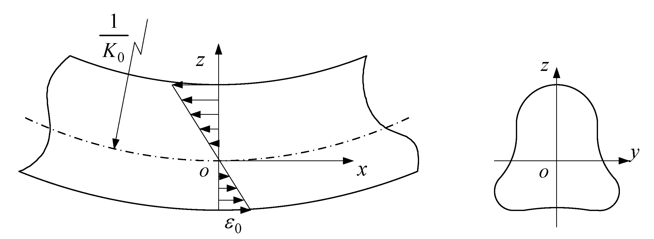
2.1. Basic Assumptions

Since the pure-bend and over-bend straightening process for an in-plane curved beam with a symmetrical section is an in-plane bending problem, some concepts are introduced which were defined in the springback theory of small curvature plane bending [26].
(1)
Plane-curved beam: the cross-sectional centroid curve of the beam; that is, the axis is an in-plane curve, which is different from a straight beam and a space-curved beam, and the plane where the axis lies is called the bending plane;
(2)
Micro-beam section: an infinitesimal beam along the core line of cross-section can fully reflect the geometry information of the cross-section;
(3)
In-plane bending of the curved beam: the load applied to the curved beam only causes its deformation in the initial bending plane.
According to the above definition, for the plane-curved beam segment with any symmetrical section shown in Figure 2, the rectangular coordinate system o x y z is established with the geometric center point o as the coordinate origin. Then, x o z is the bending plane, y o z is the cross-section of the micro-beam section, and K 0 is the initial bending curvature of the geometric center layer of the section.
At the same time, since the over-bend straightening process is a small deformation, the following basic assumptions of engineering problems are introduced.
(1)
Neutral layer coinciding: the strain neutral layer, stress neutral layer, and geometric neutral layer always coincide during the deforming process;
(2)
Plane section: any cross-section of the curved beam remains a plane before and after deformation, and the cross-section is not distorted. Therefore, the strain on the cross-section is linearly distributed;
(3)
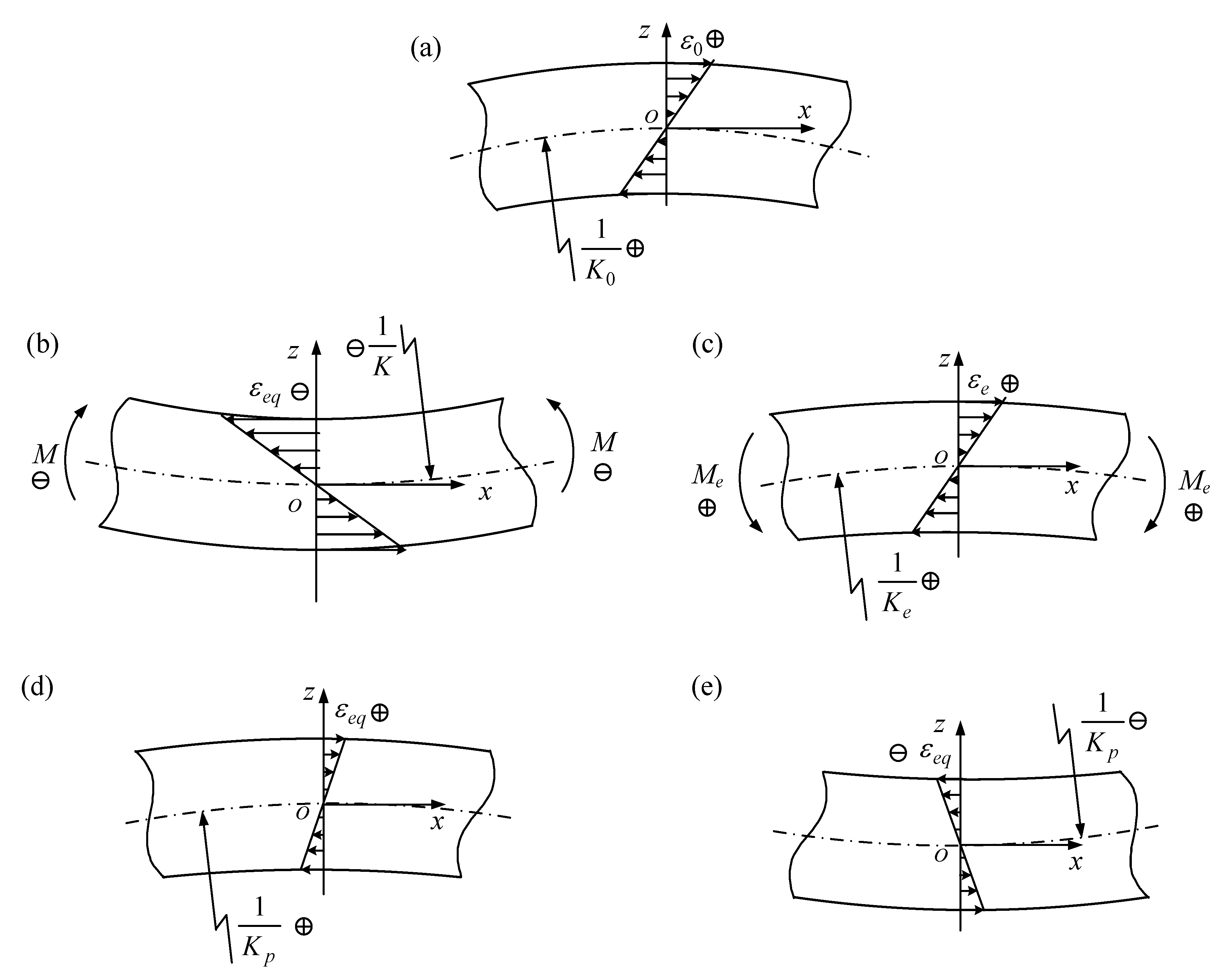
Conventional elastic-plastic material model: the curved beam is a continuous homogeneous linear elastic body, which is consistent with Hooke’s law and classical elastic-plastic unloading law, as shown in Figure 3. The stress–strain relationship during loading is
σ = f ( ε )
f ( ε ) 0
where σ is the true stress, and ε is the true strain.
(4)
Initial equivalent strain: the initial curvature of the initial micro-beam section is K 0 , and the initial equivalent strain is ε 0 , where it is assumed that the curved beam is obtained by bending the straight beam in some way, and there is no distortion of the cross-section. According to the basic Assumption (2), the initial equivalent strain should satisfy the relationship:
ε 0 = z K 0
where z is the distance from the neutral layer. Further, after pure bending of the curved beam, the equivalent strain ε e q considering the initial curvature is:
ε e q = ε + ε 0

2.2. Symbol System

To unify the curvature and moment, the symbol system is defined as follows: the normal direction of the geometric center layer of the curved beam with a circular cross-section is the z coordinate axis, the tangent direction is the x coordinate axis, and the upward direction is the positive direction of the z coordinate axis. The curvature of a curved beam is positive when it is positive in the z -axis; otherwise, it is negative. Bending with a greater bending curvature is defined as forward bending, and the loading moment is positive; otherwise, it is reverse bending, and the moment is negative. Thus, both the bending curvature and the bending moment are vectors.
According to the above definition, the over-bend straightening process can be either positive pure bending or reverse pure bending, as shown in Figure 4, which depends on the establishment of a coordinate system.

2.3. Springback Analysis in Over-Bend Straightening

According to the above definition and curvature change, over-bend straightening process can be considered as that the curvature of the geometric center layer changes from K 0 to K under the action of the loading bending moment M and then changes to 0 after springback so as to achieve a straight state, as shown in Figure 5.
According to the springback equation of plane bending with small curvature, the springback equation of a plane-curved beam with a symmetrical section in pure bending is
K p = K M E I
where K and K p are the curvature of the neutral layer of the curved beam after loading and unloading, respectively, M is the loading moment, E is the elastic modulus, and I is the sectional moment of inertia.
According to the Assumptions (2) and (4), the true strain ε of a curved beam in pure bending is
ε = ε e q ε 0 = ( K K 0 ) z
According to the mechanics of materials, the moment of a curved beam with any section is equal to the integral of the moment of the infinitesimal element on the whole section area. Therefore, the moment in the loading process can be simply described as
M = A σ z d A
where A is the cross-sectional area.
According to the basic Assumption (3) and Equations (6) and (7), the loading moment is
M = A f [ ( K K 0 ) z ] z d A
The purpose of straightening is to make the curvature after springback be 0; that is, K p = 0 . Therefore, from Equation (5), the springback equation in the over-bend straightening process of plane-curved beam is
M = K E I
For the pure-bend and over-bend straightening process of curved beam with an arbitrary symmetrical section, if the material properties, section shape, and initial curvature are known, the theoretical straightening curvature K and the theoretical straightening moment M can be obtained by combining the section equilibrium Equation (8) and the springback Equation (9).
The above analysis shows that for the in-plane curved parts with known symmetrical section shape, material properties, and initial curvature K 0 ( x ) , if the theoretical straightening moment M ( x ) is applied to the corresponding section by some technical means so that the curvature distribution after bending is K ( x ) , then one-time complete straightening can be realized in theory. In other words, the essence of over-bend straightening technology of a plane-curved beam with a symmetrical section is the loading process of the theoretical straightening moment or the realization process of the theoretical straightening curvature.

3. Process Mechanism of Over-Bend Straightening

Based on the over-bend straightening theory, straightening is to realize straightening moment by using load control or to realize straightening curvature by using mold surface control. In contrast, curvature control has poor flexibility and higher difficulty or cost. Therefore, the following analyzes the mechanism of three straightening processes by controlling the load.

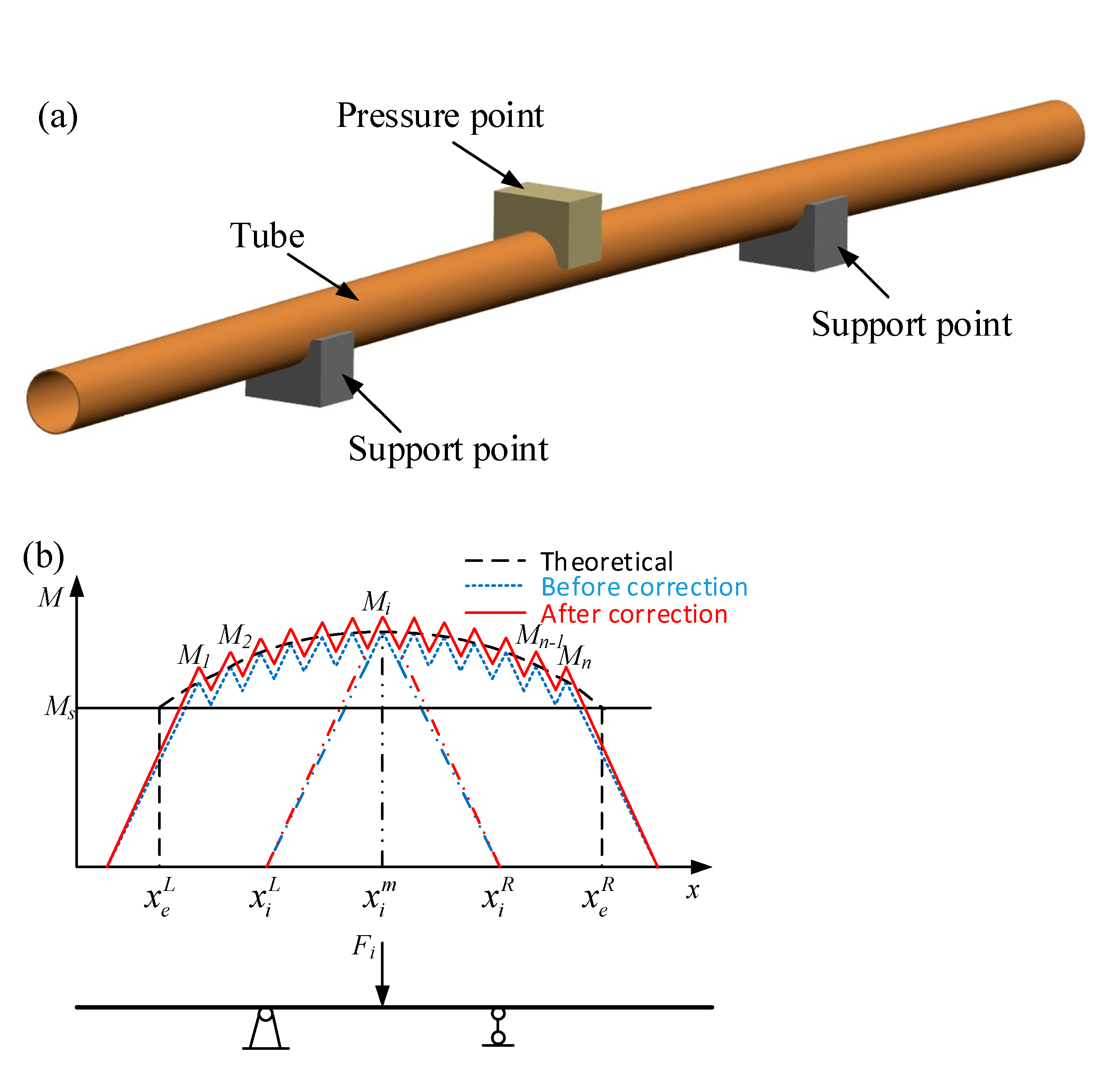
3.1. Three-Point Multi-Step Mold-Straightening Process

3.1.1. Straightening Mechanism and Strategy

Three-point mold-pressing is the most commonly used over-bend straightening process; that is, the maximum bending position of the curved workpiece placed on the two support points with adjustable distance is pressured and reaches the straight state after springback. When the initial deflection is small, the straightness can be repaired to within the requirements by a single press, and in practice, it is often necessary to load multiple times to correct the larger deflection.
Based on the over-bend straightening theory and the traditional pressure straightening method, the three-point multi-step mold-straightening process is proposed, and the process principle and straightening mechanism are shown in Figure 6. The straightening device consists of a pressing point and two supporting points symmetrically distributed. In the single straightening process, the workpiece has elastic-plastic deformation under the action of pressing point, where the load distribution is a moment diagram of an isosceles triangle, and the essence is symmetrical three-point bending. Then, the tube is moved to repeat the three-point bending, along with the triangle superposition forming a zigzag moment diagram. Therefore, the straightening mechanism of three-point multi-step mold-straightening process is to approach the theoretical straightening moment of a smooth continuous curve with the loading moment of a zigzag line.
In the three-point multi-step mold-straightening process, the actual loading moment of the finite three-point bending is always less than the theoretical moment, and the fewer the number of straightening, the greater the error. As a result, to obtain the straightening effect equivalent to the theoretical moment with less bending, a macroscopic load correction factor is introduced to compensate for the zigzagged polyline, and the load correction coefficient is greater than 1. In this paper, the optimization method of load correction coefficient based on equal bending deformation energy was adopted.
According to the over-bend straightening theory and mechanism, the straightening strategy and process planning steps of the three-point multi-step mold-straightening process are determined as follows:
(1)
Determine the initial curvature distribution K 0 ( x ) and material performance parameters;
(2)
Calculation of theoretical straightening moment distribution M ( x ) : the moment is calculated according to the section shape, material performance, and initial curvature distribution;
(3)
Process planning: determine span L (generally 1/3–2/3 of tube length), straightening times n , left support point position x 1 L of the first straightening and right support point position x n R of the n -th straightening, and calculate the support point and pressure point positions of the i -th ( 1 i n ) straightening as follows:
{ x i L = x i m L / 2 x i m = x 1 m + i 1 n 1 ( x n m x 1 m ) x i R = x i m + L / 2
where x i L , x i m , and x i R are the positions of the left support point, the pressing point, and the right support point of the i -th straightening, respectively.
(4)
Determine the load correction coefficient λ :
Specifically, the bending deformation energy under the theoretical moment M ( x ) and the actual loading moment M ( x , n , λ ) is U t r and U e q , respectively, and a correction factor with the minimum difference between the two energies is defined as the optimal value. Further, the expression of energy difference U can be obtained from the relationship between moment and curvature as follows:
U = | U t r U e q | = | x e L x e R { K 0 ( x ) K ( x ) M ( K 0 ( x ) , K ) d K K 0 ( x ) K ( x , n , λ ) M ( K 0 ( x ) , K ) d K } d x | = | x e L x e R K ( x , n , λ ) K ( x ) M ( K 0 ( x ) , K ) d K d x |
where K ( x , n , λ ) is the geometric neutral layer curvature of the cross-section after M ( x , n , λ ) is loaded at position x . After the number of bending is determined, the above equation is optimized according to the golden segmentation to calculate the optimal load correction factor λ .
(5)
Determine the straightening load: the straightening force F i at the i -th straightening is calculated as
F i = λ M i ( x i R x i L ) ( x i R x i m ) ( x i m x i L )
where M i is the theoretical straightening moment at pressure point x i m .
(6)
Pressure straightening: press and straighten the workpiece according to the predicted process parameters;
(7)
Detect the residual straightness: the residual deflection after the straightening is detected, and then straightness is calculated and evaluated; if unqualified, repeat the above steps for second straightening; otherwise, the straightening is finished.

3.1.2. Process Evaluation

The three-point multi-step straightening technology is an over-bend straightening process controlled by moment. It can press a continuous large arc into several small arcs with an S-shaped distribution by mold pressing. The pure-bend and over-bend straightening theory can provide theoretical support and technical guidance for this process to improve the accuracy.
However, there are two problems in this molding method:
(1)
Based on the straightening theory, the macro load correction coefficient can reduce the error between the actual load and the theoretical calculation to obtain a better straightening effect but not eliminate it. Therefore, this method does not fully realize the continuous and complete loading of the theoretical straightening moment;
(2)
In the straightening process, the pipe has been moved many times, and the pressure point has to be loaded and unloaded repeatedly, so the straightening efficiency is low.

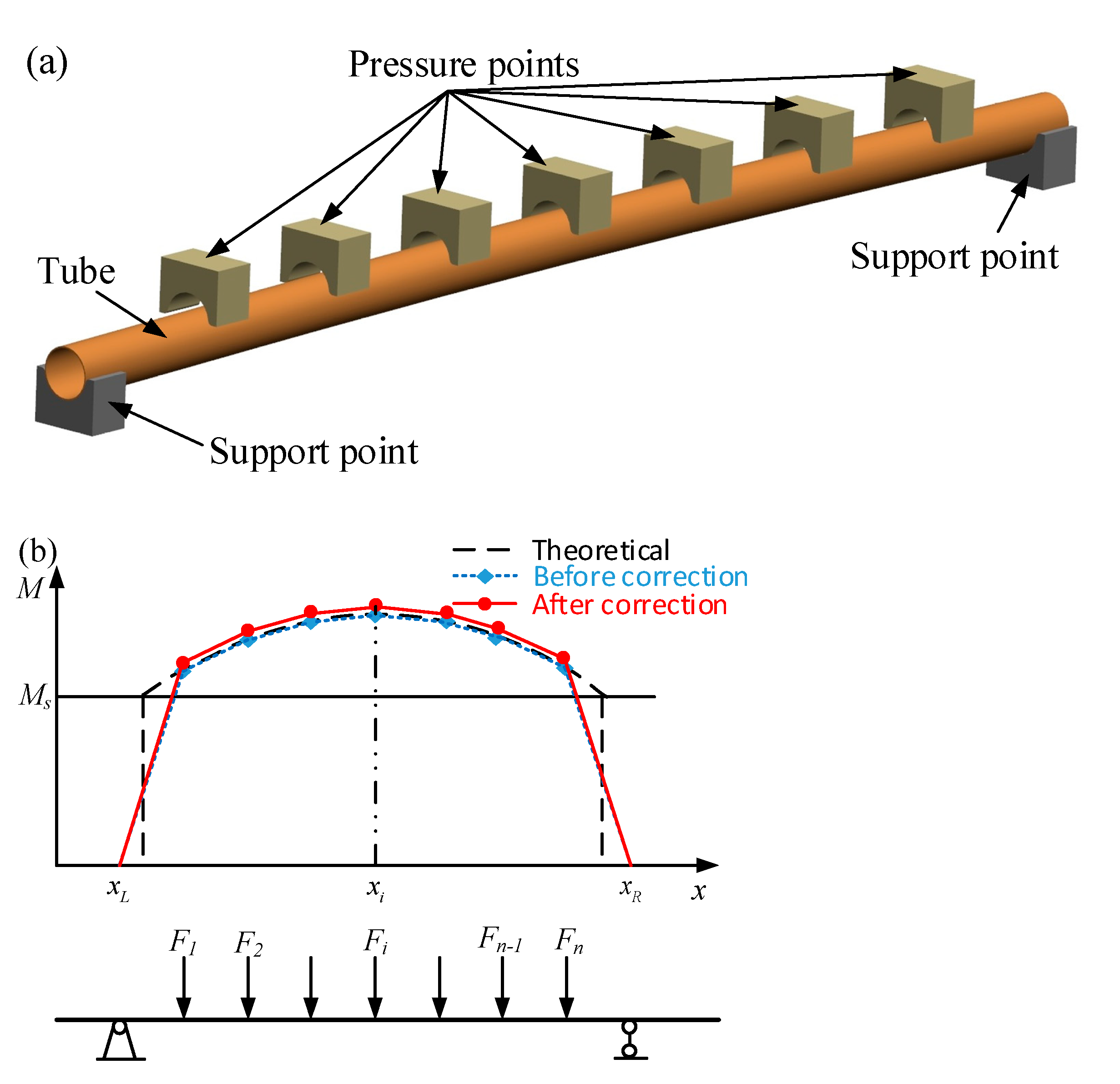
3.2. Multi-Point One-Time Mold-Straightening Process

3.2.1. Straightening Mechanism and Strategy

In the three-point multi-step mold-straightening process, repeated loading and unloading lead to low efficiency. In view of this problem, a multi-point one-time mold-straightening process is further proposed, as shown in Figure 7. The straightening mechanism of this technology is to discretize the theoretical straightening moment distribution curve and use the broken line to approach the continuous curve. Therefore, this method also needs a load correction coefficient, which is similar to the three-point multi-step straightening process.
According to the process mechanism, the straightening strategy and process planning steps were established as follows:
(1)
Determine the initial curvature distribution and material performance parameters;
(2)
Calculate the theoretical straightening moment distribution M ( x ) ;
(3)
Process planning: determine the positions x L and x R of supporting points at both ends and the number of pressing points n (usually n 3 ). Calculate the position of the i -th ( 1 i n ) pressing point as follows:
x i = x L + i x R x L n + 1
(4)
Determine the load correction coefficient λ ;
(5)
Determine the straightening load: according to the theoretical straightening moment M i at the i -th pressing point x i , determine the straightening force F i as
F i = { λ · ( M 1 x 1 x L · x 2 x L x 2 x 1 M 2 x 2 x 1 )                                                             i = 0 λ · ( M i 1 x i x i 1 + M i x i x i 1 · x i + 1 x i 1 x i + 1 x i M i + 1 x i + 1 x i )       1 < i < 0 λ · ( M n 1 x n x n 1 + M n x n x n 1 · x R x n 1 x R x n )                                     i = n
(6)
Pressure straightening: according to the predicted parameters to straighten the workpiece by mold pressing;
(7)
Check the straightness after straightening: if the straightness after straightening is unqualified, repeat the above steps for the second straightening; otherwise, the straightening is finished.

3.2.2. Process Evaluation

Based on the pure-bend and over-bend straightening theory, it can be seen that the multi-point one-time straightening process has not fully realized the continuous and complete loading of the theoretical straightening moment, which is similar to the three-point multi-step mold-straightening process.
At the same time, this method realizes one-time straightening by simultaneously pressing multiple pressure points, which requires each point to be equipped with an independent pressure control system to provide different loads. Imperfectly, this puts forward higher requirements for straightening equipment and increases the production cost of pipes.

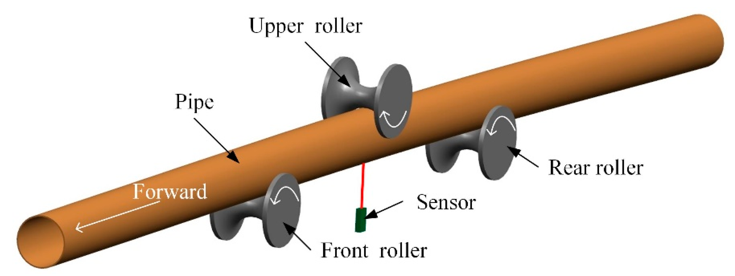
3.3. Three-Roll Continuous Straightening Process

3.3.1. Straightening Mechanism and Strategy

The three-roll continuous straightening process was innovatively put forward in Ref. [1] to solve the problems of the above two technologies; that is, the actual loading moment is not the theoretical value. As shown in Figure 8, in a roll system composed of one upper roll and two lower rolls, the rotation of the upper roll drives the axial movement of the tube, while the continuous loading realizes the complete theoretical moment and one-time continuous straightening. It is convenient to install a laser displacement sensor between the two lower rollers by using its structural features, which can realize the on-line deflection detection at the same time.
As shown in Figure 9, the flow of the three-roll continuous straightening process is determined as follows:
(1)
Deflection detection and straightness calculation: according to the local deflection detected by the laser displacement sensor, calculate the overall deflection and straightness and determine whether straightening is required;
(2)
Theoretical straightening moment calculation: calculate the initial curvature distribution according to the overall deflection K 0 ( x ) and the corresponding theoretical straightening moment distribution M ( x ) based on the pure-bend and over-bend straightening theory;
(3)
Process planning: determine the distance L between the two lower rollers;
(4)
Overall deflection control: the workpiece is continuously bent according to the predicted parameters;
(5)
Residual deflection detection: the laser displacement sensor is used to detect the residual deflection and calculate the straightness to determine whether it is qualified.

3.3.2. Process Evaluation

Compared with the current straightening process, the technical advantages of the new process are as follows:
(1)
Using roller straightening instead of traditional mold-pressing can greatly improve straightening efficiency;
(2)
The continuous loading and precise control of the upper roll can completely load the theoretical moment to the corresponding section to achieve the precise straightening;
(3)
The integration of deflection detection and continuous straightening on one equipment simplifies the process flow and is easy to realize intellectualization.

4. Experimental Study on Three-Roll Continuous Straightening Process for Tube
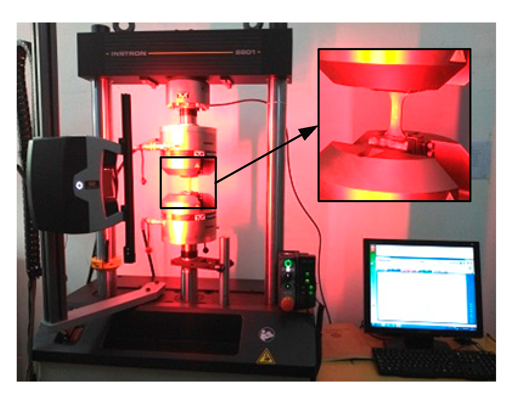
4.1. Measured Tubes

The measured tubes were commercially available cold-drawn pipes of ASTM 1020 steel with straightness standards. In order to study the straightening process, curved tubes must be prepared first, but the material properties will change due to the Bauschinger effect. Therefore, a tension–compression loading test was carried out INSTRON 8801 testing machine, as shown in Figure 10. According to the fatigue test standard [27], a full-thickness longitudinal arc test piece was processed. The experimental data were fitted by the bilinear hardening material model of which the stress–strain relation is be shown in Equations (15) and (16). The results accompanied by the geometric dimensions are shown in Table 1.

4.2. Experimental System and Scheme

The three-roller continuous straightening process uses roller loading instead of the step-by-step loading of traditional molding, and the process based on closed-loop control is easy to achieve high accuracy and automation. Considering the laboratory conditions, a semi-automatic three-roll continuous straightening system was set up [1], which integrated deflection detection and continuous straightening, as shown in Figure 11.
In order to improve the prediction accuracy of the theoretical straightening moment and reduce the distortion of the cross-section, the roller design principle of equal diameter holes was adopted; that is, the radius of the straightening roller was 30.2 mm, and the span of the two lower rollers was determined to be 400 mm.
The working principle and experimental scheme were as follows:
(1)
Curved tube preparation: using a three-roll continuous straightening experimental system to roll straight tube to prepare different initial curvature distribution;
(2)
Deflection detection and deflection curve fitting: detect the local deflection, and use the eighth-order polynomial fitting to calculate the overall deflection distribution and straightness;
(3)
Calculation of straightening moment and straightening load: according to the initial deflection curve and over-bend straightening theory, calculate the theoretical straightening moment and load distribution;
(4)
Overall deflection control experiment: according to the calculated load, three-roll continuous straightening experiment was carried out to correct the overall deflection distribution;
(5)
Straightness inspection: local deflection inspection and overall deflection calculation were carried out for the straightened tube to evaluate whether the straightness is qualified.

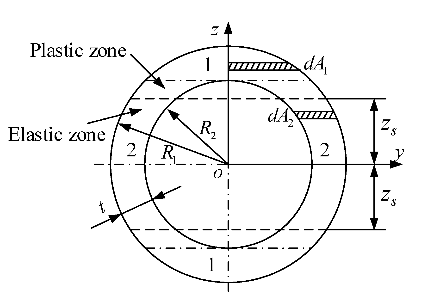
4.3. Theoretical Straightening Moment Calculation

For a small deformation, the bilinear hardening model is used [2] to describe the stress–strain relationship of the material:
σ = { D ε + σ 0                                 ε > σ s E E ε               σ s E     ε   σ s E   D ε σ 0                           ε < σ s E
σ 0 = ( 1 D E ) σ s
where σ s is the yield stress and D is the plastic modulus.
In the circular section of the pipe, as shown in Figure 12, the coordinate system is established with the geometric center as the coordinate origin. According to the area expression d A of the micro-element, the cross-section is divided into two regions, Zone 1 and Zone 2, and the corresponding micro-element area is:
d A = { d A 1 = R 1 2 w 2 d z z [ R 1 , R 2 ] [ R 2 , R 1 ] d A 2 = ( R 1 2 w 2 R 2 2 w 2 ) d z z [ R 2 , R 2 ]
where R 1 is the outer radius, and R 2 is the inner radius. The moment of inertia of the circular section is
I = π 4 ( R 1 4 R 2 4 )
During the straightening process, the micro-beam with an initial curvature K 0 undergoes a pure-bending elastoplastic deformation under the action of the moment M . z s is defined as the boundary position of the elastic-plastic distinction on the section. According to its value, that is, the deformation state of the section, the reverse pure bending of the micro-segment of the curved beam with a ring section can be divided into three stages.
The first stage is the full elastic deformation of the micro-beam; that is, z s > R 1 . In this process, the relationship between the sectional moment and the curvature of geometric neutral layer can be obtained from Equation (7) as
M = A σ z d A = A E ( K K 0 ) z 2 d A = E ( K K 0 ) [ A 1 z 2 d A 1 + A 2 z 2 d A 2 ]   = E I ( K K 0 )
After unloading, the micro-beam springback to the initial state; that is, K 0 . When z s = R 1 , the moment is defined as the elastic ultimate moment M s . It can be seen from Equations (6) and (19)
M s = I σ s R 1
It can be seen that the elastic ultimate moment M s is not related to K 0 but only to the geometric size and material properties of the tube.
The second stage is the plastic deformation of Zone 1; that is, R 2 < w s < R 1 and M > M s . According to the section equilibrium Equation (7), the relationship between moment M and curvature under loading K is
M = 4 ( z s R 1 ( σ 0 + D ε ) z d A 1 + R 2 z s E ε z d A 1 + 0 R 2 E ε z d A 2 ) = 4 σ 0 3 ( K K 0 ) 3 [ ( K K 0 ) 2 R 1 2 ε s 2 ] 3 2 + 1 2 ( E D ) ( K K 0 ) R 1 4 arcsin ( ε s ( K K 0 ) R 1 ) + π 4 ( K K 0 ) ( D R 1 4 E R 2 4 ) + σ 0 2 ( K K 0 ) 3 ( 2 ε s 2 [ ( K K 0 ) R 1 ] 2 ) [ ( K K 0 ) R 1 ] 2 ε s 2 = f 1 ( K , K 0 )
With the increase in the loading moment M , the plastic deformation of the section gradually extends to the center. It is defined that the moment when the plastic deformation just occurs at z = R 2 is the boundary moment M d , which is determined by Equation (6) as
M d = 4 ( R 2 R 1 ( σ 0 + D ε ) z d A 1 + 0 R 2 E ε z d A 2 ) = 4 3 σ 0 ( R 1 2 R 2 2 ) 3 2 + π σ s 4 E R 2 ( D R 1 4 E R 2 4 ) + σ 0 R 2 [ R 1 4 2 arcsin ( R 2 R 1 ) + R 2 2 ( 2 R 2 2 R 1 2 ) R 1 2 R 2 2 ]
In this case, the curvature of the central layer is defined as the boundary curvature K d , and its expression is
K d = M d E I ε s R 2
When M M d , the plastic deformation does not penetrate into the inner diameter of the pipe. On the contrary, it can be inferred that the inner area produces plastic deformation. Moreover, it can be seen from Equations (22) and (23) that the boundary moment M d has nothing to do with the curvature K d and K 0 but only with the geometric size and material properties.
The third stage is the plastic deformation in the inner diameter area of the section; that is, z s < R 2 . In this process, M > M d , and the relationship between moment M and curvature K is satisfied
M = 4 ( R 2 R 1 ( σ 0 + D ε ) z d A 1 + w s R 2 ( σ 0 + D ε ) z d A 2 + 0 w s E ε z d A 2 ) = 1 2 ( E D ) ( K K 0 ) [ R 1 4 arcsin ( ε s ( K K 0 ) R 1 ) R 2 4 arcsin ( ε s ( K K 0 ) R 2 ) ]         + 4 σ 0 3 ( K K 0 ) 3 { [ ( K K 0 ) 2 R 1 2 ε s 2 ] 3 2 [ ( K K 0 ) 2 R 2 2 ε s 2 ] 3 2 }     + π 4 D ( K K 0 ) ( R 1 4 R 2 4 )   + σ 0 ( 2 ε s 2 [ ( K K 0 ) R 1 ] 2 ) 2 ( K K 0 ) 3 [ ( K K 0 ) R 1 ] 2 ε s 2 σ 0 ( 2 ε s 2 [ ( K K 0 ) R 2 ] 2 ) 2 ( K K 0 ) 3 [ ( K K 0 ) R 2 ] 2 ε s 2 = f 2 ( K , K 0 )
It can be seen from Equations (19), (21) and (24) that the initial curvature K 0 directly affects the relationship between the loading moment M and the loading curvature K . In addition, according to the definition of the symbol system, the direction of the initial curvature K 0 and the loading moment M is always the opposite, no matter in the forward or reverse bending. Therefore, according to the relationship between the initial curvature | K 0 | and the boundary curvature | K d | , the solution of theoretical straightening curvature K by combining Equations (9), (21), and (24) is
K = { f 1 ( K , K 0 ) E I + K 0                   | K 0 |     | K d | f 2 ( K , K 0 ) E I + K 0                   | K 0 |   >   | K d |
The theoretical straightening moment M can be further determined by substituting the above result into Equation (9).

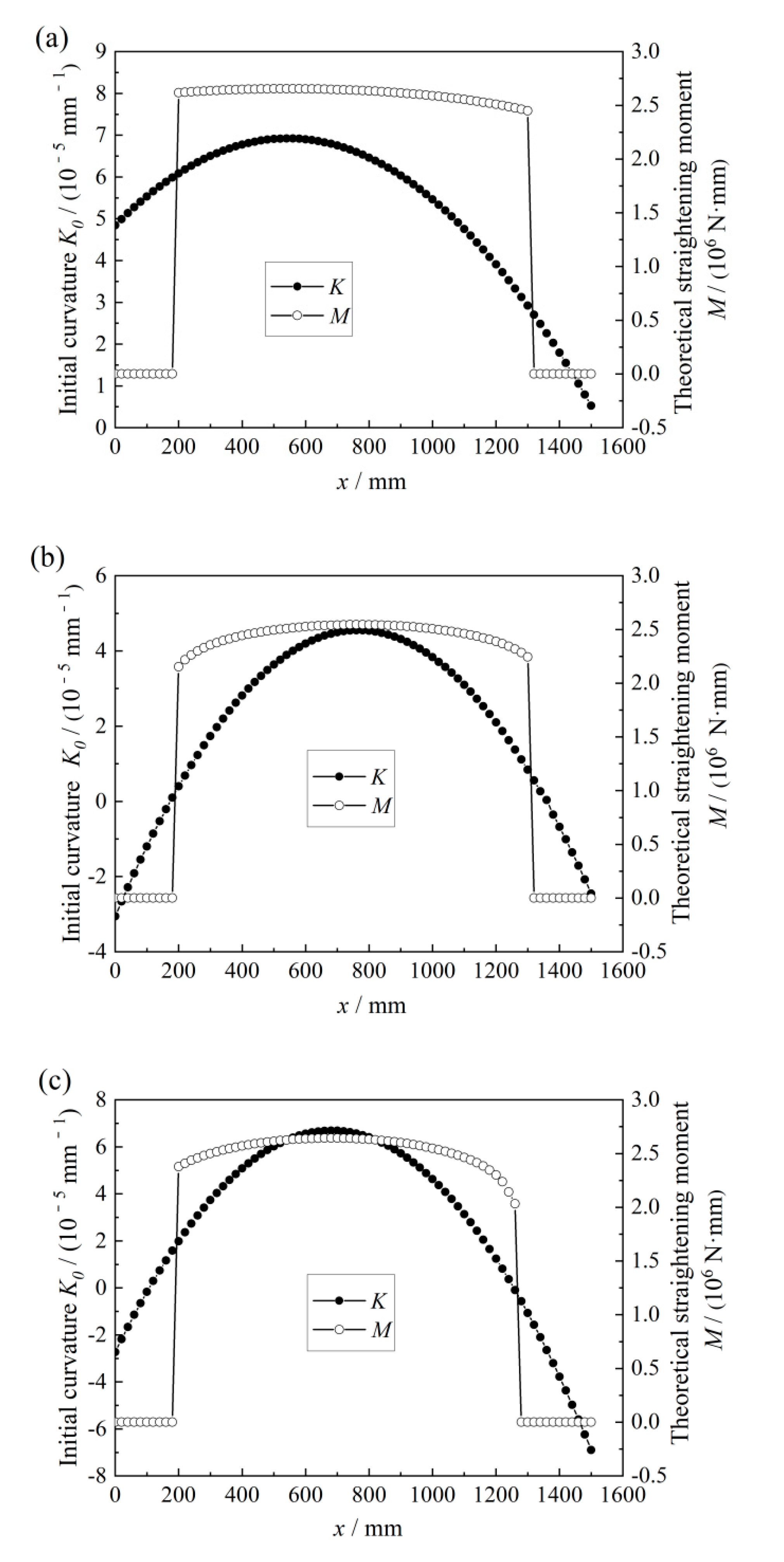
4.4. Results and Discussions

Using the three-roll continuous straightening experimental system, the deflection of three curved pipes was detected, and the theoretical straightening moment was calculated according to the above theory and process, as shown in Figure 13.
The straightness of the straightened pipe as 1.29‰, 1.62‰, and 1.09‰, which were all controlled within 1.50‰ to meet the general engineering requirements. This shows that the over-bend straightening theory could predict the load required for straightening an in-plane curved pipe and also verifies the feasibility of the three-roller continuous straightening process.

5. Conclusions

(1)
A pure-bend and over-bend straightening theory for in-plane curved beam with symmetrical section was proposed based on the springback theory of small curvature plane bending. According to the general theory, the essence of the over-bend straightening process was revealed; that is, straightening is the loading process of the theoretical straightening moment or the realization process of the theoretical straightening curvature.
(2)
The straightening mechanism of the existing over-bend straightening process was analyzed based on the pure-bend and over-bend straightening theory. Specifically, a zigzag bending moment was applied in the three-point multi-step straightening process to approximate the smooth curve of theoretical straightening moment, while the multi-point one-time straightening technology was to discretize the theoretical distribution curve using the broken line, so both of them needed a load correction coefficient to compensate the error between the actual load and theoretical calculation.
(3)
Aiming at the problem of the mold-press straightening process, the three-roll continuous straightening process was proposed. The theoretical straightening moment is fully loaded into the corresponding section through the continuous loading of the upper roll, which theoretically realizes the one-time straightening. Moreover, the roll-pressing instead of mold-pressing can greatly improve the straightening efficiency.
(4)
Based on the over-bend straightening theory, and the characteristics of the annular section of the tube, a calculation model of the straightening moment distribution related to the initial curvature was further established.
(5)
The three-roll continuous straightening experiments were carried out, and the results showed that the straightness of the straightened tube could be controlled within 1.5‰, which meets the standard requirements. Therefore, it is suggested that the over-bend straightening theory can predict the load required for straightening an in-plane curved part, and the three-roller continuous straightening process is an efficient and highly accurate straightening technique.

Author Contributions

Conceptualization, C.W. and W.L.; methodology, G.Y. and J.Z.; software, C.W. and G.Y.; validation, C.W., G.Y. and J.Z.; formal analysis, W.L.; investigation, C.W.; resources, C.W. and J.Z.; data curation, C.W.; writing—original draft preparation, C.W. and W.L.; writing—review and editing, C.W. and W.L.; visualization, G.Y.; supervision, G.Y. and J.Z.; project administration, C.W. and W.L.; funding acquisition, C.W. and G.Y. All authors have read and agreed to the published version of the manuscript.

Funding

The authors would like to thank the National Natural Science Foundation of China (Grant NO: 52005431), National Natural Science Foundation of Hebei province (Grant NO: E2020203086), and Ningbo key research and development plan in 2022 (Grant NO: 2022Z057).

Institutional Review Board Statement

Not applicable.

Informed Consent Statement

Not applicable.

Data Availability Statement

Not applicable.

Conflicts of Interest

The authors declare that they have no conflict of interest.

Notations

σ true stress
ε true strain
ε 0 initial equivalent strain
ε e q equivalent strain
K 0 initial bending curvature
K the curvature after loading
K p the curvature after unloading
M loading moment
F straightening force
E Young’s modulus
I the sectional moment of inertia
A cross-sectional area
L span, the distance between the two lower rollers
λ load correction coefficient
M ( x ) theoretical straightening moment distribution
K 0 ( x ) initial bending curvature distribution
U bending deformation energy
D 0 outer diameter of pipe
twall thickness of pipe
Dplastic tangent modulus
σ s yield strength
M s elastic ultimate moment

References

  1. Wang, C.G.; Yu, G.C.; Wang, W.; Zhao, J. Deflection detection and curve fitting in three-roll continuous straightening process for LSAW pipes. J. Mater. Process. Technol. 2017, 255, 150–160. [Google Scholar] [CrossRef]
  2. Wang, C.G.; Zhang, Z.Y.; Zhai, R.X.; Yu, G.C.; Zhao, J. Cross-sectional distortion of LSAW pipes in over-bend straightening process. Thin-Walled Struct. 2018, 129, 85–93. [Google Scholar] [CrossRef]
  3. Yu, G.C.; Zhai, R.X.; Zhao, J.; Ma, R. Theoretical analysis and numerical simulation on the process mechanism of two-roller straightening. Int. J. Adv. Manuf. Technol. 2017, 94, 4011–4021. [Google Scholar] [CrossRef]
  4. Meng, Q.D.; Zhao, J.; Mu, Z.K.; Zhai, R.X.; Yu, G.C. Springback prediction of multiple reciprocating bending based on different hardening models. J. Manuf. Process. 2022, 76, 251–263. [Google Scholar] [CrossRef]
  5. Zhao, J.; Song, X.K.; Cao, H.Q.; Liu, J. Press straightening control strategy of multi-step three-point bending for LSAW pipes. J. Harbin Inst. Technol. 2014, 46, 90–96. [Google Scholar] [CrossRef]
  6. Zhao, J.; Song, X.K.; Cao, H.Q.; Liu, J. Principle of Multi-point Bending One-off Straightening Process for Longitudinally Submerged Arc Welding Pipes. Chin. J. Mech. Eng. 2014, 50, 92–97. [Google Scholar] [CrossRef]
  7. Li, J.; Xiong, G.L. Study on calculation method of press straightening stroke based on straightening process model. In Key Engineering Materials; Trans Tech Publications Ltd.: Stafa-Zurich, Switzerland, 2007; Volume 340–341, pp. 1345–1350. [Google Scholar] [CrossRef]
  8. Pei, Y.-C.; Wang, J.-W.; Tan, Q.-C.; Yuan, D.-Z.; Zhang, F. An investigation on the bending straightening process of D-type cross section shaft. Int. J. Mech. Sci. 2017, 131–132, 1082–1091. [Google Scholar] [CrossRef]
  9. Song, Y. Load-deflection model for T-section rail press straightening process under lateral loads. Clust. Comput. 2018, 22, 2955–2961. [Google Scholar] [CrossRef]
  10. Yin, J.; Zhao, J.; Wang, S.; Li, Y. Multiroller straightening analytical model of H-beam. Ironmak. Steelmak. 2013, 41, 521–528. [Google Scholar] [CrossRef]
  11. Liu, X.W.; Zhang, S.Q.; Wang, H.G.; Liu, H.S. Theoretical research of residual stress on H-beam roller straightening. In Advanced Materials Research; Trans Tech Publications Ltd.: Stafa-Zurich, Switzerland, 2012; pp. 258–262. [Google Scholar] [CrossRef]
  12. Huang, X.; Yu, G.; Sun, H.; Zhao, J. A mechanical model of axial and circumferential bidirectional deformation for large thin-walled pipes in the process of continuous and synchronous calibration of roundness and straightness by three rollers. Int. J. Adv. Manuf. Technol. 2021, 116, 3809–3826. [Google Scholar] [CrossRef]
  13. Huang, X.Y.; Yu, G.C.; Wang, C.G.; Zhao, J. Deformation mechanism analysis of three-roller continuous and synchronous calibration process of straightness and roundness for LSAW pipes. Int. J. Adv. Manuf. Technol. 2022, 121, 1731–1742. [Google Scholar] [CrossRef]
  14. Guan, B.; Zang, Y.; Wu, D.; Qin, Q. Stress-inheriting behavior of H-beam during roller straightening process. J. Mater. Process. Technol. 2017, 244, 253–272. [Google Scholar] [CrossRef]
  15. Ma, R.; Wang, C.G.; Zhai, R.X.; Zhao, J. An iterative compensation algorithm for springback control in plane deformation and its application. Chin. J. Mech. Eng. 2019, 32, 212–223. [Google Scholar] [CrossRef]
  16. Mu, Z.; Ma, R.; Zhao, J.; Yu, G.; Sun, H. Research on iterative compensation method for springback control based on implicit equation. Int. J. Mater. Form. 2021, 14, 1097–1108. [Google Scholar] [CrossRef]
  17. Hong, L.; Xiong, X. Research on straightening process model based on iteration and self-learning. In Proceedings of the 2016 IEEE 11th Conference on Industrial Electronics and Applications (ICIEA), Hefei, China, 5–7 June 2016; pp. 2400–2406. [Google Scholar] [CrossRef]
  18. Song, D.F. Numerical Simulation of Straightening of Steel Pipe for Press Straightening Machine. Adv. Mater. Res. 2010, 145, 493–498. [Google Scholar] [CrossRef]
  19. Nassiraei, H.; Lotfollahi-Yaghin, M.; Ahmadi, H.; Zhu, L. Static strength of doubler plate reinforced tubular T/Y-joints under in-plane bending load. J. Constr. Steel Res. 2017, 136, 49–64. [Google Scholar] [CrossRef]
  20. Nassiraei, H.; Rezadoost, P. Local joint flexibility of tubular T/Y-joints retrofitted with GFRP under in-plane bending moment. Mar. Struct. 2021, 77, 102936. [Google Scholar] [CrossRef]
  21. Huang, X.Y.; Yu, G.C.; Zhai, R.X.; Ma, R.; Zhou, C.; Gao, C.L.; Zhao, J. Roller Design and Numerical Simulation of Three-roller Continuous and Synchronous Adjusting Straightness and Roundness Process on LSAW Pipes. Chin. J. Mech. Eng. 2021, 57, 148–159. [Google Scholar] [CrossRef]
  22. Meng, Q.; Yu, G.; Huang, X.; Sun, H.; Zhao, J. Study on a straightening process by reciprocating bending for metal profiles. Met. Res. Technol. 2021, 118, 605. [Google Scholar] [CrossRef]
  23. Lee, J.-S.; Huh, H.; Bae, J.-G.; Lee, J.-W.; Kim, D.-T. Design Optimization of Roller Straightening Process for Steel Cord using Response Surface Methodology. AIP Conf. Proc. 2007, 908, 581–588. [Google Scholar] [CrossRef]
  24. Cao, H.Q.; Yu, G.C.; Yang, C.F.; Zhao, J. Research on a Control Strategy of the Symmetrical Four-Roller Bending Process Based on Experiment and Numerical Simulation. Symmetry 2021, 13, 940. [Google Scholar] [CrossRef]
  25. Timakov, E.V.; Dubinskiy, F.S. Numerical Analysis and Simulation of the Straightening Process of Heavy Rails on a Horizontal Roller-Straightening Machine. In Materials Science Forum; Trans Tech Publications Ltd.: Stafa-Zurich, Switzerland, 2019; Volume 946, pp. 775–781. [Google Scholar] [CrossRef]
  26. Zhao, J.; Yin, J.; Ma, R. Springback equation of small curvature plane bending. Sci. China Technol. Sci. 2011, 54, 2386–2396. [Google Scholar] [CrossRef]
  27. American Society of Testing Materials. Standard Practice for Strain-Controlled Fatigue Testing; American Society for Testing and Materials: West Conshohocken, PA, USA, 1998. [Google Scholar]
Figure 1. The straightening forming methods for in-plane curved parts. (a) Three-point press straightening; (b) Parallel-roller straightening.
Metals 12 01362 g001
Figure 2. The cross-section and coordinate of the curved beam.
Metals 12 01362 g002
Figure 3. Conventional elastic-plastic material model.
Metals 12 01362 g003
Figure 4. Symbol system in over-bend straightening. (a) Forward bending, (b) reverse bending.
Metals 12 01362 g004
Figure 5. Curvature and strain in the over-bend straightening. (a) Initial, (b) loading, (c) unloading, (d) after springback ( K 0 and K p have the same sign), and (e) after springback ( K 0 and K p have the opposite sign).
Metals 12 01362 g005
Figure 6. Three-point multi-step mold-straightening process. (a) Schematic diagram and (b) straightening principle, where M s is the elastic ultimate moment.
Metals 12 01362 g006
Figure 7. Multi-point bending one-off straightening process. (a) Schematic diagram and (b) straightening principle.
Metals 12 01362 g007
Figure 8. Three-roll continuous straightening process [1].
Metals 12 01362 g008
Figure 9. The technological process of three-roll continuous straightening.
Metals 12 01362 g009
Figure 10. Tension–compression loading test [1].
Metals 12 01362 g010
Figure 11. Semi-automatic experimental prototype: (1) hydraulic system, (2) electrical control system, (3) CMM, (4) force sensor display instrument, (5) laser displacement sensor display instrument, (6) hydraulic cylinder, (7) frame, (8) workbench, (9) handwheel, (10) reducer, (11) block, (12) roller, (13) pipe, (14) sprocket chain, (15) laser displacement sensor, (16) balance device, and (17) force sensor [1].
Metals 12 01362 g011
Figure 12. Circular section of tubes.
Metals 12 01362 g012
Figure 13. The initial curvature and the theoretical straightening moment distribution of the experimental curved tubes. (a) Tube 1, (b) Tube 2, and (c) Tube 3.
Metals 12 01362 g013
Table 1. Geometric dimensions and mechanical properties of tube [1].
Outer Diameter
D 0 /mm
Wall Thickness
t/mm
Length
L/mm
Young’s Modulus
E/GPa
Plastic Tangent Modulus
D/MPa
Yield Strength σ s /MPa
633.1150020421,684253
Publisher’s Note: MDPI stays neutral with regard to jurisdictional claims in published maps and institutional affiliations.

