Review

Development of Carbon Nanotube (CNT)-Reinforced Mg Alloys: Fabrication Routes and Mechanical Properties

1
Department of Mechanical Engineering, GLA University, Mathura 281406, Uttar Pradesh, India
2
Department of Mechanical Engineering, Lingayas Vidyapeeth, Faridabad 121002, Haryana, India
3
Department of Mechanical Engineering, UIET, Panjab University, Chandigarh 160014, India
4
Department of Medical Physics, Hilla University College, Babylon 51002, Iraq
5
School of Mechanical Engineering, Lovely Professional University, Phagwara 144411, Punjab, India
6
Peter the Great St. Petersburg Polytechnic University, 195251 Saint Petersburg, Russia
7
Division of Research & Innovation, Uttaranchal University, Dehradun 248007, Uttarakhand, India
*
Authors to whom correspondence should be addressed.
Metals 2022, 12(8), 1392; https://doi.org/10.3390/met12081392
Submission received: 12 June 2022 / Revised: 27 July 2022 / Accepted: 28 July 2022 / Published: 22 August 2022

Abstract

:
Properties such as superior specific strength, being imponderous, and the ability to reprocess are the key features that have drawn attention to magnesium. In the last few years, applications such as automotive, aerospace, and medical applications have been seeking light-weight equipment, and light-weight materials are required for making them. These demands were matched by developing metal matrix composites with magnesium as a base and reinforced with carbon nanotubes (CNTs), grapheme nanoplatelets (GNPs), or ceramic nanoparticles. CNTs have been adopted for developing high-strength metal matrix composites (MMCs) because of their delicately superior thermal conductivity, surface-to-volume ratio, and tensile strength, but lower density. In developing high-performance light-weight magnesium-based MMCs, a small number of CNTs result in refined properties. However, making Mg-based MMCs has specific challenges, such as achieving uniform reinforcement distribution, which directly relates to the processing parameters. The composition of CNT, CNT sizes, their uniform distribution, Mg-CNT interfacial bonding, and their in-between alignment are the characteristic deciding factors of Mg-CNT MMCs. The current review article studies the modern methods to develop Mg-CNT MMCs, specifications of the developed MMCs, and their vital applications in various fields. This review focuses on sifting and summarizing the most relevant studies carried out on the methods to develop Mg-CNT metal matrix composites. The article consists of the approach to subdue the tangled situations in highlighting the Mg-CNT composites as imminent fabrication material that is applicable in aerospace, medical, and automotive fields.

1. Introduction

In the current scenario, light in weight and high strength are the prime features of the materials used in aerospace, medical, and automotive applications. The property of magnesium that enables it to be used in vital applications is its density of 1.738 g/cm3, which is nearly two-thirds of aluminum, making it the lightest structural material. In addition, some other properties, such as the ability to reprocess, its appreciable damping character, treatable machinability, good electromagnetic shielding, and plenteousness, make Mg an adequate selection among all other materials [1,2,3]. Due to these properties, the abovementioned applications have adopted magnesium as a prime material [4,5,6]. However, corrosion resistant strength and mechanical strength are the properties in which magnesium is inferior to aluminum. Mg alloys consists hexagonally closed packed crystal structure (HCP) and atomic packing in HCP does not allow slipping to occur easily, due to this Mg alloys offers restrictions in deformation at normal temperature conditions. The strength of Mg alloys can be further increased by reinforcing them with metallic particulates, ceramic particulates, and carbon fiber reinforcing agents [7,8,9]. Recently, as Mg-based composites have attracted attention, their mechanical and electric properties are being enhanced to a higher level by incorporating reinforcing agents, such as carbon nanotubes (CNTs) and graphene nanoplatelets (GNPs). This has evolved into a wide research area [10,11,12]. The exclusive optical, electrical, thermal and mechanical characteristics and the enhanced surface area and aspect ratio make CNTs a superior candidate for vital application areas [13,14]. Studies have revealed that CNTs contain diamond and graphite characteristics. It has been said that due to their possession of high conductivity with regard to thermal as well as electric behavior, they are as formable as graphite and hard as diamond [15]. Studies have confirmed that the CNT-reinforced composites have significantly improved characteristics due to their high modulus and strength of CNTs. Photovoltaic cells, fuel cells [16], energy depository products [17], physical properties detectors and responding devices, amplification devices, electron escape process guns, energy source inverters [17,18], medicine distribution systems [19], and biological sensors [20] are the various other fields of applications of CNTs. Conclusively, a new research area in the field of material science has been explored by incorporating nanotechnology in developing metal matrix nanocomposites (MMNCs).
Recently, many studies have been carried out on developing metal matrix composites (MMCs) reinforced with CNTs, especially aluminum and copper particulates [20,21,22]. In addition, in depth work has already been carried out on CNTs reinforced with polymer matric nanocomposites (PMNCs), and various advantageous outcomes have already been drawn [23,24,25]. The application of carbon nanoparticles in the metal matrix is still a hot cake in research due to the challenges in its homogeneous distribution [23,26,27] and inferior wettability. This poor wettability in CNT arises due to its considerable surface tension difference from metals. This difference is responsible for the development of weak interfacial bonding between the metal matrix and the CNT. Studies have shown that in polymer matrix nanocomposites, the constituents interact at the molecular level and highly refine the composite’s properties. However, this phenomenon has not yet been studied in the metal matrix composites composed of CNTs. Several investigations have been carried out using various fabrication processes to conquer the issue of uniform distribution of carbon constituents in the metal matrix [28,29,30,31,32,33].
Hence, the generation of lumps of nano-reinforcement and permeability in the synthesis and fabrication process are the areas that need to be resolved for CNTs to be considered as a prime choice for developing MMCs. The earlier gravity casting method was found unsatisfactory due to the low yield point of the developed nanocomposites. This low yield point is caused by its high permeability. However, these permeability levels can be reduced by techniques such as squeeze casting. The distribution of reinforcing particles and reduction in the formation of lumps are factors of the development techniques that are adopted to develop the metal matrix nanocomposites (MMNCs) [34]. These development techniques can be categorized generally as liquid state and solid-state techniques. Casting under the liquid state category and powder metallurgy under solid state are two techniques that are utilized in developing particle-reinforced magnesium-based composites. Several investigations have been performed to develop magnesium-based composites and to study their characteristic behavior using the powder metallurgy route [14,30,31,32,33,34,35,36]. The powder metallurgy process is a chain of various processes, creating the uniform mixture of fine powders of constituents, compacting the uniform constituent’s mixture, and finally sintering the compacted shape. The steps mentioned above are executed to enhance the density of the composites by minimizing the porosity level. The properties of the composites, such as poor ability to machine, appreciably low fracture toughness, and inferior tendency to deform easily, can be overcome easily by reducing the size of the reinforcement from the particle to nano level and as a result, the characteristics are refined. These appreciable enhancements in mechanical characteristics are due to grain refinement and Orowan strengthening. The attention-catching factor of metal matrix nanocomposites (MMNCs) is their creep resistive property even at high temperature conditions, and this property becomes more anticipatory in the magnesium-based MMNCs. Several studies have been carried out on strengthening Mg/CNT composites to refine their mechanical characteristics [33,37,38]. Emerging of various innovative fields of application of nanotechnology in recent time, have contributed to a significantly reasonable decrease in the cost of CNTs [39]. As a result, CNT nano particles are currently available as chief reinforcing agents for developing Mg-based nanocomposites at reasonable prices. The current review article is a summary of the studies that have been conducted about the objectives of refining the mechanical, corrosion, and tribological characteristics. This article also involves the development-related suggestions/findings of authors in their respective research towards the development of Mg/CNT composite materials.

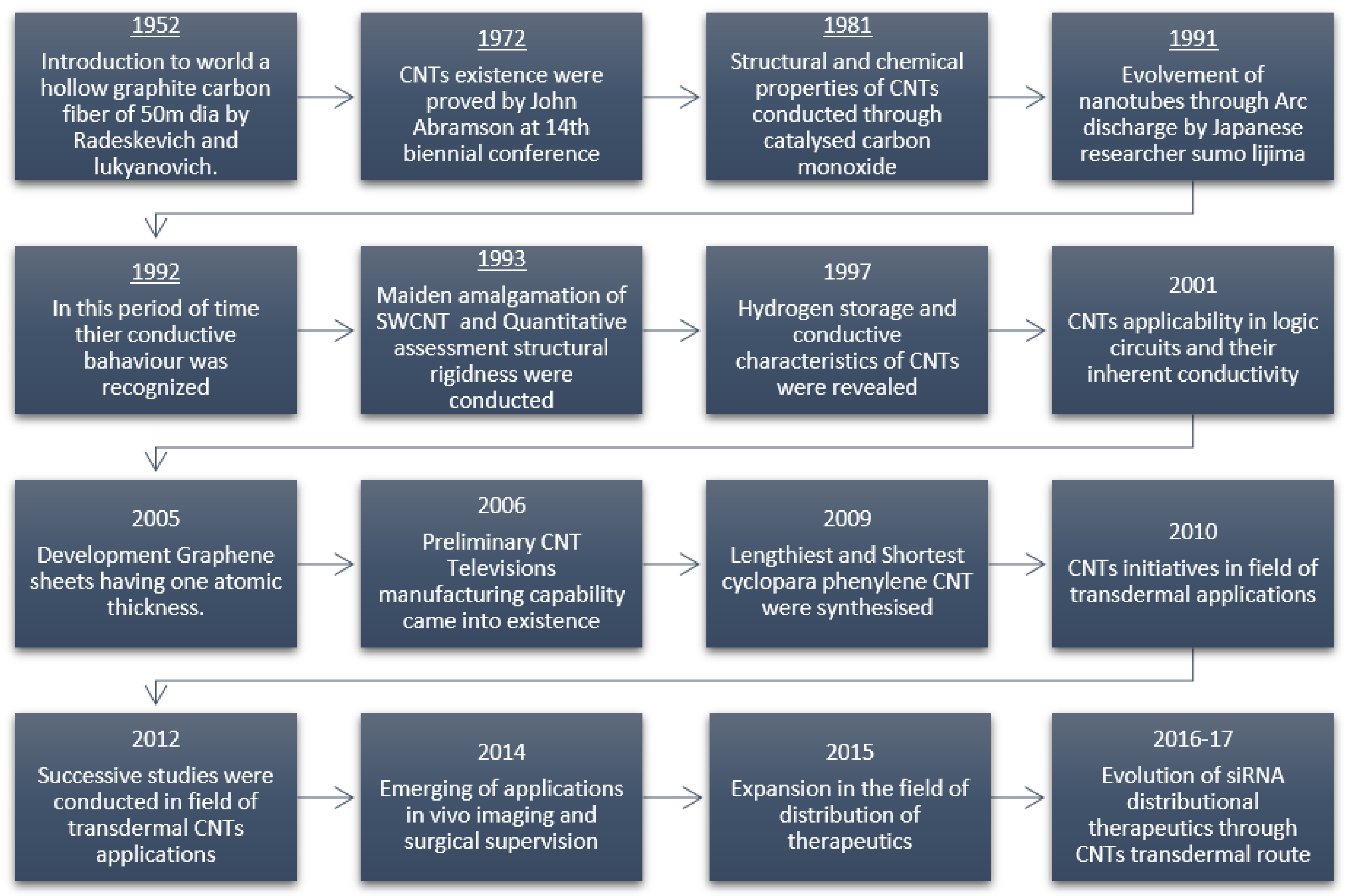
2. Carbon Nanotubes (CNTs)

At the beginning of the 1990s, during the study of spherical carbon molecules in electric arc equipment, Japanese scientist Sumino Iijima unintentionally found the existence of coaxial nanotubes of carbon molecules [40]. The mentioned carbon atom layer, graphene, was loped in a cylindrical shape for developing CNTs. These coaxial tubes were called multi-walled carbon nanotubes (MWCNTs) [41]. Later, Iijima and Ichihashi and their teammates, based on the above findings, further investigated and successfully found refined single-walled carbon nanotubes (SWCNTs) [42]. The configurations of carbon atoms in SWCNTs and MWCNTs are depicted in Figure 1. The techniques adopted by Iijima et al. for developing MWCNTs, consisting of diameters up to 100 nm, were further utilized with minor adjustments to develop the SWCNTs. The SWCNTs were designed by transforming the single graphene sheet to a cylinder-shaped tube (0.4 to 2.5 nm diameter) by rolling and they were extensively adopted due to their outstanding electrical, optical, physical and chemical characteristics. The property of SWCNTs that empowers them to carry numerous molecules in π-π piling connections is due to their well-defined walls, possessing extremely high surface areas [43]. Rather than being straight, these nanotubes curled and coiled towards inside, having the diameter of about 1 nm [43,44]. CNTs has evolved into the most widely explored nanostructured materials, due to the availability of their extremely unique characteristics, such as high flexibility, enhanced strength, sp2 hybridized carbons, and the capability to align those atoms in rope-like structures [45,46,47,48,49]. Figure 2 shows the historical evolvement of CNTs, which involves the wide developments that were achieved during its journey. Since 2010, some extraordinary notable applications of CNTs have evolved [20].
The axial dimensions of CNT are in microns and in radial direction they are in nano size. As a one-dimensional nanomaterial, their surface area ranges from 50 to 1315 m2/g. The property that makes CNT a low weight nanomaterial is its lower density of about 1.3 g/cm3. The aspect ratio of CNT is much more refined compared to conventional fiber materials, ranging from 100 to 1000. The most stable carbon–carbon covalent bonds can assume the strength of CNT in their carbon loops, which possess heat conductivity of nearly 3000 W/mK. This much high thermal conductivity of CNT is analogous to the thermal conductivity of diamond. CNT holds some unique mechanical, thermal and electrical characteristics, along with a lower density, which plays a role in the development of strengthened MMNC. Studies has been executed to find the rigidity, strength and density of the CNT relative to the values of steel. It has already been stated by some researchers in their respective investigations that the density of CNT is extremely low. In a relative study of CNT with steel, the density was approximately one-sixth of that of steel, the strength was found to be approximately 100 times higher and Young’s modulus was approximately 1 TPa. This Young’s modulus is analogous to diamond and is the maximum value among all the carbon allotropes [51]. These unique characteristics of CNT have evolved due to the carbon–carbon (C-C) bond that they possess with a sp2 hybridized nature [15,17,18]. By containing higher stiffness as compared to diamond, CNTs also have appreciable formability because of their locked and muffled configurations [52]. As a result, the CNTs can deform their structure to a small angle ring shape when subjected to external stresses and can regain their previous shape after the removal of stresses. Stone–Wales defects are a kind of defect studied in CNTs, which has become advantageous for them with regard to deformation beyond the elastic range. Due to this defect, CNTs have developed the capability to bear 40% of the applied tensile strain without undergoing brittle failure [53]. Electrolysis, chemical vapor deposition, arc evaporation, laser ablation, and flame synthesis are the various CNT development techniques. The techniques that are adopted the most for the production of CNTs are the vacuumed depositing method, metal depositing through dispersal of arc and photoablation [54]. The above-mentioned unique characteristics of CNTs make them suitable for use in various fields of applications.

3. Carbon Nanotube-Reinforced Mg Composites

In recent times, it has been observed that rigorous and vital investigations have been conducted to decrease the weight of the materials used in various applications without compromising their strength. These investigations are specially carried out for the materials used in automobile and aerospace applications [55]. The density of magnesium has been found to be even lower than aluminum and titanium. The characteristics of magnesium that restrict its use in industrial applications are its inferior ductility and lower strength. These inferior characteristics of Mg are due to its hexagonally closely packed (HCP) crystal structure [54,55]. Because of the mentioned restrictions with magnesium, it is required to improve the characteristics of magnesium to enhance its use in various applications by adding reinforcing agents through different process routes. For increasing the strength and other characteristics of pure magnesium, involvement of nanoscale reinforcing agents, such as GNPs, Al2O3, SiC, and CNTs, in Mg matrices have been performed [28,56,57]. The low density and attractive strength of CNT make them an attractive selection among other reinforcing agents reinforced in the Mg matrix [5,6]. Highly stiff and strengthened MMCs may develop through the addition of CNTs in Mg matrices. The characteristics such as high ultimate strength (approximately 30 GPa) and great Young’s modulus, of developed MMCs enhances by these CNTs addition [11,14,58,59,60].
Furthermore, CNTs have also emerged as a reinforcing agent to improve the characteristics of Mg alloys, such as AZ81 [61] and AZ31 [59,60,61,62], monolithic Mg [11], and Mg-6AL [63]. However, MMCs developed through reinforcing CNTs do not possess mechanical properties that are as refined as when they ae reinforced with nano-platelets (GNPs). This deficiency in the properties of MMCs developed with CNTs is due to the inferior reinforcement bonding with the Mg matrix material. This inferior bonding is due to CNT’s inferior wettability in Mg matrix material. Utilization of Mg and its alloys in various fields of applications is poor due to the different inferior characteristics that they possess, such as poor anti-corrosive strength, less formability, and inferior mechanical characteristics. The poor anti-corrosive characteristic of Mg and its alloys is due to their lower standard electrode potential (−2.36 V), resulting in interaction with other elements, enhancing corrosion in Mg [59,60,62,63]. Hence, the frequency of corrosion deposition in monolithic Mg becomes unexpectedly unstable at the ppm level, due to the amalgamation of contaminations of Fe, Cu, or Ni [64]. CNTs have been introduced into the matrix of Mg material to enhance the characteristics of Mg and its alloys. However, the effect of this amalgamation of CNTs on the inferior anti-corrosive characteristic of Mg has not been thoroughly studied [65]. Possibly, attractive changes in the corrosive behavior of Mg material could emerge by reinforcing CNT particles because of its unique electrical characteristics relative to all its allotropes. The corrosive behavioral changes in the Mg alloy AZ31, when subjected to the CNT reinforcing agents, were studied by Fukuda et al. [66].
Furthermore, potential surface investigations, immersion, and polarization examinations of CNT-reinforced AZ31 were performed to obtain accurate results on the corrosion behavior changes [67,68]. The study mentioned the above-concluded remarkable changes in corrosion behavior of MMC due to the galvanic corrosion development in-between the Mg matrix and the CNTs. For further refinement of the characteristics of MMCs reinforced with CNTs, the uniform distribution of CNTs in the Mg matrix is needed. Numerous approaches have been implemented to achieve a more uniform distribution of CNTs.

4. Fabrication Routes to Fabricate Mg-CNTs Composites

Magnesium-based MMCs reinforced with CNT material have been developed by incorporating numerous development routes [31,35,36,53,55]. Among all the development routes of Mg/CNT MMC, the most acceptable method is powder metallurgy. Figure 3 depicts various development routes that have been incorporated to develop Mg/CNT MMCs [11,15]. Even in numerous routes, the uniform distribution of CNT particles in the Mg matrix is still a tedious job because of the clustering of CNT particles. This clustering is due to the poor wettability of CNT. The poor wettability of CNT is also responsible for inferior bonding between CNTs and Mg matrix material. Inferior bonding alters the load transfer between CNTs and the Mg matrix [59,66]. Numerous process routes have been adopted to develop Mg/CNT MMCs to achieve uniform distributions; they can be categorized as follows: liquid distribution routes (ultrasonic curing and mechanical stirring, gemini dispersant), apparent physical reformation (ball milling (BM)), friction stir welding (FSW), applying glazing material (such as Si [69], Ni [70], and MgO [71]) to CNTs to enhance their wettability, doping of CNTs and hybridization of CNTs with other materials (such as hybrid Al-CNT reinforcement [72]). The investigations have concluded that CNTs’ distribution in the Mg matrix with the stir casting process route is extremely non-homogeneous because of the lower wettability of CNT particles in a molten matrix of Mg [14,34]. However, outstanding distribution of CNTs has been observed in some development routes, such as ball milling. However, they harm the apparent physical structure of reinforced CNTs, resulting in lower strength of MMCs.

4.1. Powder Metallurgy (PM)

Many investigations have been carried out to develop Mg/CNTs through the powder metallurgy route [30,57,71,72,73]. The general powder metallurgy route involves the following steps: obtaining a mixture of Mg and CNT particles by mechanical alloying or grinding, compression of the developed mixture through sintering. Some other processes for obtaining more refined characteristics are also performed with regard to further sintering, such as hot and cold pressing and spark plasma sintering. The investigations that have been carried out so far to develop the Mg/CNT MMCs majorly abide by specific post-processing of deformation, such as extrusion and rolling. These investigations were focused on obtaining a uniform distribution of CNT in the Mg matrix by developing good bonding between CNT and Mg, irrespective of the process route phases. These phases and their respective characteristic parameters are discussed in the following sections.

4.1.1. Ball Milling (BM)

The process of producing powders of composite materials and blending them to obtain a uniform mixture is known as mechanical alloying [74,75]. For the development of Mg/CNT MMCs, researchers have performed numerous investigations with the adoption of significant modifications in their process routes to encounter the issues discussed in the above section. Zou et al. [74] have investigated the effects on MMC, developed with various compositions of CNT and varying porosities in the Mg matrix. The process route that they adopted for developing MMCs was power metallurgy, which comprised processes of mixing, compressing, and sintering powder material. First, powdered Mg and CNTs were mixed to obtain a uniform mix; furthermore, this mix was compressed in a true shape die and lastly, the compressed and compacted shape of the powder mixture was sintered in a furnace to obtain the final strengthened product. Li et al. [76] also developed Mg/CNT MMCs with the same powder metallurgy route, but they followed certain specific process restrictions in the process. Thornby J. et al. [77] fabricated Mg-based composite material reinforced with 0, 0.25, 0.5, and 0.75 vol.% of CNTs through the PM route. The prime objective of the study was to analyze the creep-deformational analysis of the fabricated composites with nano-indentation. The matrix material was blended with reinforcing agents through a ball milling machine for 2 h at 200 rpm; the produced blend was compacted, followed by sintering in hybrid microwave at 640 °C for 15 min and left for 1 h for further soaking to 400 °C in a constant temperature-maintained oven. For producing the fabricated material in billet form, it was extruded at 350 °C with the extrusion ratio 20:25:1. For analyzing the creep deformation, a two-step test was adopted by incorporating a shielded environment of Ar gas. In the primary stage, any of the three 0.5, 5, or 50 /s loading rates at any of 298, 373, 473 and 573 K temperature were applied to each of the sample to a maximum loading of 50 MN. In the secondary stage, the duration for which the indentation load was consistently applied was 120 s, and then the deformational behavioral data were documented. Fewer micro-cracks and grain modifications were observed in the microstructural investigation relative to pure Mg, which promoted the improvement in material ductileness. It was observed that the dimensions of indentation at elevated temperature conditions did not deviated by much extent; this is due to the agglomeration of the large number of developed dislocations. The variation in the modulus of elasticity for different compositions was observed to be limited at 373 K, although it was found to be reductive until the vol.% of the CNTs was raised to 0.5 and abruptly increased at 0.75 vol.% of the CNTs. The creep deformation characteristics of the fabricated composites were observed as the only function of the testing temperature and were unaffected by the loading rate of the CNTs. Habibi et al. [72] have developed Mg-based MMC by using Al and CNT nanoparticle hybrid reinforcement. The process route that they adopted was PM and the Al content in the hybrid reinforcement that they used was approximately 1 wt.%. Their process was initiated with the mixing of Mg powder with hybrid reinforcing nanoparticles by adopting ball milling. This uniform mix was then compressed in die to create an initial bond between the discrete powder particles under a pressure of 97 bars. These compressed and compacted geometries were heated/sintered in an advanced oven, which had a two-way sintering feature. For fusing the powders into one another, the molded shape of the powder was heated to their melting point temperatures, and finally, the sintered material was extruded. Their study found the satisfactory distribution of hybrid reinforcing agents up to 1 wt.% of Al and further increasing the composition of Al showed the agglomeration of the reinforcing agents. Goh et al. [31] also adopted the PM process route for developing Mg/CNT MMC. Their study found an appreciable adherence among the reinforcing agent CNT and the matrix material Mg. However, this adherence between the particles was completely mechanical, and no chemical binding was involved.

4.1.2. Ball Milling (BM) Followed by Direct Current Sintering

Due to time, the powder metallurgy process route has evolved by adopting certain modifications in its processes, for example, the conventional sintering of PM was replaced by hot press sintering (HPS) [71,73]. The study followed the mentioned modification in PM and has shown remarkable improvement in the hardness, bending strength and compressive strength of the developed Mg/CNT MMC. The process of hot press sintering is basically the sintering of powder mix along with compression, which endorses the changes in their microstructure due the development of linkages in CNTs [71,78]. Endu et al. [79] proposed in their study that the anticorrosive nature of MMNC could be boosted by adding certain reinforcing agents in the Mg matrix. In their study, they developed composites by using AZ91 as the matrix material and MWCNTs as the reinforcing agent through the PM route. Their process of development of MMNCs began with grating the AZ91D alloy into a fine powder by processing the AZ91D alloy through a ball miller with argon shielding. Furthermore, this grated powder was mixed with the reinforcing agent MWCNT in the same ball miller. The uniform mixture of the matrix and reinforcing material then underwent hot pressure sintering (HPS). The hot sintered part was further extruded, and certain post processes, such as solution curing and aging, were performed. These post processes are performed for further enhancement of the anticorrosive nature of the MMNCs. Ding, Y. et al. [73] developed MMNCs by grating pure Mg by employing a high energy ball milling (HEBM) setup, which provided argon shielding. During this ball milling, a controlling agent (stearic acid) was added. These milled, pure Mg granulates were further mixed with CNTs of 1 vol.% through the previously used HEBM. This uniform mix of CNTs and Mg further underwent HPS to be sintered. Li, Q. et al. [78] introduced CNTs into Mg matrix material in an enhanced composition of 2 wt.%. The process of development of MMNC included the dry powder mixing of Mg and CNT. The mixtures produced were sintered in a vacuum environment using HPS; a compacting pressure of 50 MPa for 30 min was utilized, along with sintering at 600 °C. For the final touch to the samples, hot isostatic pressing (HIP) was performed at 600 °C for a duration of 60 min. The researchers concluded that the above-mentioned processes result in regular distribution of reinforcing agents in the Mg matrix.

4.1.3. Pulsed Electric Current Sintering (PECS)

Researchers have further modified the PM process that was adopted to develop CNT-reinforced Mg composites, in which sintering was replaced by pulsed electric current sintering (PECS) [57,64,77]. The application of sparks in the PECS sintering process involves pressure, electric field diffusion, and heating. In PECS, the methodology adopted for rapid heating of the powder mix is carried out by passing the AC supply through the die containing the powder mixture of the matrix and reinforcing agent [78,79,80,81]. Due to this, the powder contained in the die has a high density and low porosity in the sintered part. The applicability of PECS was assumed by the fact that even in a short period of PECS sintering, the chances of agglomeration of CNT particles in Mg matrix were lowered significantly. Adopting the PECS technique reduces the chances of agglomeration and reduces the need for post-processing material formation [14].

4.2. Semi-Powder Metallurgy (SPM)

The research above has proven that grating the powder of Mg and producing a homogenous mix with CNTs using the ball mill is tedious. The tediousness of the ball milling process is because the process depends on various processing factors; also, the processing through cluster balls produces heat that may result in the fusion of Mg powder. Additionally, the ball milling process also ruptures the geometry and unique structure of the CNTs, which results in less strengthened composite development. To overcome these issues, semi powder metallurgy (SPM) came into existence to develop MMNCs. Here, in the SPM technique, a liquid solvent is utilized rather than planetary clustering in ball milling for developing the mix of the matrix material and reinforcing agent [28,79,80,82]. A study and its associated investigations revealed that an appreciable amount of local pressure of approximately 50 MPa was generated due to ultrasonic cavitation [83,84]. This noticeable amount of local pressure enhanced the mechanical properties of the developed composite by achieving refined distribution of CNTs in the Mg matrix. Abazari S. et al. [85] fabricated Mg-3Zn/CNTs composites through the semi powder metallurgy route. The process was initiated by developing the Mg-3Zn alloy through the ball milling process in a shielding environment of Ar gas. Before introducing the reinforcing CNTs to the matrix material, they were acidic and treated with sulfuric and nitric acids. To observe the effect of CNTs on the properties of the fabricated composites, samples were created with 0, 0.2, 0.4 and 0.8 wt.% of CNTs. The Mg-3Zn alloy was magnetically stirred with ethanol for 1 h at 600 rpm; simultaneously, MWCNTs associated with functional groups were separated in ethanol by ultrasonication for 1 h. A droplet of definite solution of CNTs was introduced to the powder suspension in ethanol at 600 rpm for 3 h. Furthermore, this mix was dehydrated in the vacuumed furnace at 344 K for 24 h. The dry mixture was compacted under a pressure of 650 MPa, sintered at 874 K for 2 h, and at the last extrusion based on hot working was performed. The researchers concluded that semi-powder metallurgy and extrusion were efficient process routes. The microstructures improved due to the presence of functional groups associated with CNTs, which raised the nucleation sites and enhanced the strengths of the load transfer mechanisms found to be responsible.

4.2.1. Gemini Dispersant

The objective of loading the Mg matrix material with CNT reinforcing agents faces hurdles due to the clustering of the CNT particles in the Mg matrix in the process of developing the mix, which results in the degradation of unique features of CNTs, due to the generation of weak bonding between CNT and Mg particles [59,66]. The issue mentioned above can be overcome, and for obtaining the desired uniform distribution, the method of reform in covalent and non-covalent bonding is utilized and the process of doing so is termed as chemical reformation [82,83,86,87]. This chemical reformation method efficiently executes the uniform distribution of CNTs; however, this also alters the CNTs’ internal structure by inducing a covalent bonding surface through chemical and physical oxidation [86]. In recent times, researchers have investigated the use of new dispersants named gemini in respective investigations and the results has shown appealing characteristics [84,85,88,89]. The gemini dispersant constitutes two identical amphiphiles. These amphiphiles are integrated with one another through a chemical bond. Aromatic rings, hydrophilic groups, and hydrophilic chains develop these amphiphiles. The even distributions of CNTs are possible with the gemini dispersant due to the phenomena of generation of π-π assembling and also as a result of the tendency of gemini to be adsorbed on the CNTs’ surfaces [64,80,86,87,88,89]. The gemini dispersant’s hydrophobic and lipophilic nature also generates uniform distribution [90]. Hou et al. [91] developed Mg/CNT MMNCs by incorporating the gemini dispersant in the mix and the dispersants they utilized were of ionic characteristics. The researchers concluded in their study that, by using the mentioned dispersant, they achieved a more refined distribution of CNTs, even with CNT’s untouched unique structure. From the purity of the developed MMNCs, these dispersants can be extracted through annealing. To obtain the desired dispersal of the CNT particles throughout the matrix of Mg, the investigators dissolved MWCNTs in the die ionized water and ionic gemini dispersant. The authors observed in their study that the reason behind the refined distribution of the CNTs in the Mg matrix was due to the formation of negative charge in the MWCNTs developed by the DSDM route. The generated negative charge raises the intermediate particle repulsion in MWCNTs in DSDM water solution. Even more refined distribution and less agglomeration were observed in enhancing the surface potential of MWCNTs [91]. Furthermore, the powdered forms of Mg and Al were added to the MWCNT mix with a steady rate, along with moderate ethanol and to obtain a perfect mix, stirring was performed for 20 min. Vacuum distillations were performed for drying the stirred Mg-Al-MWCNT mixture. The removal of dispersant from the MWCNT mix was performed through the annealing process in an argon shielding environment. The annealed mix was placed under compression, heat-treatment, and extrusion, resulting in the development of MWCNT’s outstanding characteristics [55]. Figure 4 depicts the characteristic defining steps in the development of Mg/CNT composites through the gemini dispersant.

4.2.2. Development of CNT’s Surface Functional Groups

The development of the Mg/CNT composites is vulnerable to the agglomeration of CNTs and generation of their clusters, which occurs due to CNTs’ possession of certain unique characteristics, such as their enhanced L/D ratio, extraordinary Van der Waals force, and immense specific surface area. This clustering of CNTs in the Mg matrix is responsible for the generation of porous composites [92]. For overcoming the disadvantages of CNTs, function groups such as hydroxyls (–OH) and carboxyl (–COOH) carbonyls (>C=O) can be generated on their surfaces. The uniform distributions of CNTs were also achieved by applying sound energy to agitate the CNTs in an anhydrous ethanol solution. The process of doing so is called sonication of CNT particles, which also leads to eradicating the contamination from CNT’s surfaces [70], [75]. Rashad et al. [82], in the attempt to develop a hybrid composite, produced a slurry of powders in an Mg-3Al-1Zn composition in ethanol. Furthermore, this slurry was added to 1.5 wt.% CNTs, which were layered with nickel. The additions were executed through mechanical stirring at 1500 rpm for a duration of 2 h. Finally, vacuum filtration was performed, and the composite powder was compressed in an SS die. Fatih Aydin et al. [93] developed MWCNT-reinforced Mg composites through a process route that started with preparing the material powder through SPM, extraction and sonication using ultrasonic waves in ethanol; for distribution of CNTs, mechanical stirring was used and lastly, extrusion through dies was performed.

4.3. Extrusion Based on Hot Working

The deformation of material through cold working processes results in work-hardening of the materials. The Mg/CNT composites are deformed through hot extrusion to overcome this issue. However, the hot extrusion process is optimal only when the amount of composite material fabricated through the PM route is in a large quantity. During the development of Mg/CNT composites, the generation of carbides has been observed at the interface of the Mg matrix and CNTs when the working temperature rises above 500 °C; this leads to lower composite strength [94]. The hot extrusion step in the process route may overcome the issue mentioned above. Shimizu et al. [95] developed AZ91D alloy-based composites using MWCNT as a reinforcing agent in different wt.% compositions, ranging from 0.5 to 5 wt.%. The process route that they adopted involved ball milling, vacuum-operated HPS, and hot extrusion. In their observations, they stated that until the 1 wt.% was reached, they observed proper CNT distribution. Once it raised above 5 wt.%, they observed clusters of CNTs in the mix. In addition, they summarized that the strength of the fabricated composite was enhanced due to the lying of the shorter and in line CNTs on the outermost surface of the Mg particles, which offered restricted deformation; hence, the strength of the composite was raised. Harun Mindivana et al. [96] fabricated Mg-6Al/CNT composites and their observation was based on variations in the composition of CNTs, which were 0.5, 1, 2, and 4 wt.%. The fabrication process consisted of ball milling, cold compacting, and hot extrusion. The generated composites after hot extrusion underwent microstructural study. It was concluded that the CNTs were uniformly distributed over the Mg chips and added that this distribution of CNTs suffers from the increments in CNTs’ wt.%. In their study, Han et al. [59] summarized that the CNTs in Mg matrix material enhance the development of twinning and also deteriorate the basal consistency in Mg-based nanocomposites processed through hot extrusion.

4.4. Metal Fusion and Solidifying Technique

Plenteous attempts have been carried out to develop CNT-reinforced metal matrix composites through the melting and solidification technique. The melting and solidification route incorporates high-temperature conditions, which may affect the characteristics of CNTs and involve chemical reactions at CNT-matrix interfaces. It has been advised to include this process route in low-temperature working conditions. Furthermore, the uniform distribution of CNTs in the metal matrix through mechanical stirring is a tedious job; due to surface tension, CNTs are generally agglomerated with each other and develop in bunches. Mg’s low melting point temperature enables the incorporation of the melting and solidification route for reinforcing the Mg matrix with CNTs [14,88,93].

4.4.1. Stir Casting (SC)

The fabrication of Mg/CNT composites can also be performed through the stir casting route. However, the process of stir casting possesses certain restrictions, such as the clustering of CNT particles and oxidation of molten Mg. In addition to the issues mentioned above, the mechanical stirring in stir casting damages the unique crystallographic characteristics of CNTs, resulting in inferior mechanical characteristics of the Mg/CNT composites. The issue of clustering of CNTs in the stir casting route may be overcome by modulation and controlling the various parameters of the stir casting technique [97]. The oxidation of molten Mg can be prevented by maintaining the vacuum in the stirring container [91,94,98]. In recent times, numerous investigations have been carried out, intending to optimize the process parameters of the stir casting technique for obtaining the uniform distribution of CNT particles by overcoming the above-mentioned issues. Gupta M. et al. [99] experimented with fabricating the Mg matrix composite reinforced with different reinforcements, such as ceramic nanoparticles, metallic and CNTs. The objective of the experiment was to study the variance in mechanical characteristics of the fabricated composites [93,94,95,96,100]. The microstructural porosity in the Mg/CNT composites fabricated through the stir casting route was comparatively lower; this has been concluded by the study conducted by Tun, K.S. et al. [101]. Kumar et al. [102] fabricated AZ91D-based composite material by insertion of MWCNTs. The process route that they adopted was stir casting. In the outcome of the study, they concluded that uniform distributions of CNTs in the AZ91D matrix were observed with well-fabricated microstructures. Selvamani et al. [103] employed the semi-automatic stir casting route in their AZ91D/MWCNT fabrication process. The amount of MWCNT reinforcement that they dispersed in the Mg alloy matrix was from 2 to 4 wt.%. As a result of the study, they found that CNT particles were dispersed in the eutectic matrix and the developed composite consisted of a dendritic structure of lower porous nature in comparison to the pure Mg alloy [103]. Abbas et al. [36] conducted an experiment to decrease the porous nature of the fabricated composites through the stir casting route by increasing the amount of CNTs dispensed in the Mg matrix. Different wt.%. of MWCNTs were added in the AZ31 matrix in their composite fabrication process. This increment in mass density effectively enhanced the mobilization and compaction of metal atoms. The continuous stirring caused grains to be refined and shearing of the particles in the molten mix. Consequently, the porous nature of the composites was reduced. Additionally, they summarized the factors that influence the porous nature of the composites, which were reinforcement distribution, appreciable wettability, and effective linkages. Hong Yuan et al. [104] adopted a unique and innovative technique for developing ZM1alloy-based CNT-reinforced MMCs. A ZM1 matrix material was prepared separately, with 3.50, 5.50, 0.50–1.00, 0.10 and 0.01 wt.% of Zn, Zr, Cu, Ni, Mg and impurities, respectively. Instead of feeding the reinforcing material in o the matrix, primarily, they were pre-disbursed in Zn powder through liquid mixing and mechanical alloying. In liquid mixing, 1000 mL of ethanol was added with 10.0 g CNTs and ultrasonication was performed. Later, simultaneous sonication along with stirring were carried out after adding 3.0 g of powdered Zn to develop CNT-Zn heterogeneous solution. In the secondary stage of mechanical alloying, for obtaining the CNT-Zn mix, 10.0 g of CNTs, 3.0 g of Zn and 1.0 g of stearic acids were blended and then ball milled at 100 rpm for 4 h. For obtaining the solid pieces of CNT-Zn, the mixes obtained in both stages were further compressed through a hydraulic pressing machine. Finally, these solid CNT-Zn pieces were fed in (1.0 wt.%) as reinforcing agents in separately prepared 3.0 kg ZM1 Mg alloys through mechanical stirring. Sample testing revealed appreciable modifications in the dispersion of the reinforcing material, leading to enhanced mechanical characteristics, in addition to the fact that the fracture modes were also transformed from brittle to ductile.

4.4.2. Deposition of Disintegrated Melt (DDM)

The DDM route of fabrication of composites has been adopted generally for those fabricated with reinforcing nano-sized particles. The method involves the heating of Mg above the superheated temperature of 750 °C, which contains the provision of argon shielding. A mechanical stirrer is provided to disperse the reinforcing agents uniformly throughout. The heating pot has a bottom nozzle for pouring out the molten material, which also has the provision of disintegration with argon jets. Lastly, the poured-out material is extruded. Chan et al. [11] employed an innovative electromagnetic concept to stir the Mg/CNT molten mix. The molten pot used in the fabrication had inducting coils at the outer surface; these coils induced the magnetic field that enabled the molten mix to be stirred. Furthermore, the molten mix was heated to 700 °C in an environmentally shielded manner. Lastly, the composite slurry was poured into the die for developing the composites. Paramsothy et al. [105] conducted their experiment of developing a composite through the dispersion of CNT particles into the ZK60A matrix. The process of development was carried out through deposition of the disintegrated melt route, trailed by hot extrusion. The vibrant accumulation of composite slurry on the substrate through hot extrusion, material shielding through argon gas, and least gravity-associated segregation, due to proper selection of the stirring factors, resulted in the uniform distribution of the CNT particles.

4.5. Friction Stir Processing (FSP)

FSP is a solid phase processing approach that generates an adequate grained microstructure. Analogous to friction stir welding (FSW), a rotating tool, is adopted in the process to rotate at the substrate surface. This generates the required plastic deformation resulting from the fine and uniaxial grains on the friction plastic deformation surface. This process of development of fine and uniaxial grains is termed as dynamic recrystallization. FSP is a productive technique that is generally employed to fabricate the composites. However, it has been employed for dynamic recrystallization of the substrate surface. The outcome found by researchers in the process of Mg/CNT composite fabrication through FSP involves the welding zones of CNT and matrix material [32,101,106]. Sharma et al. [107] fabricated composites by introducing nano-sized MWCNTs and graphene as the reinforcing material to the rolled matrix material plates of AZ31B through FSP. The process constraints were as follows: axial load of 5.4 kN, transitional velocity of tool of 40 mm/min, and 2° tool inclination. The composites were fabricated with 1000, 1200 and 1400 rpm rotational tool speeds. The characteristic investigations of the developed samples revealed that tensile and compressive strength of the fabricated composites increased by enhancing the reinforcing material distribution, which was achieved through enhancing the rotational tool speed. In addition, they observed a drop in the tensile strength in the case of the hybrid composite. They concluded that the mechanical characteristics of the fabricated composites were satisfactory at a toll rotational speed of 1400 rpm. Jamshidijam, M. [108] fabricated AZ31-based composite material reinforced with MWCNTs through FSP. The FSP process involved adequately grained rigid interfacial bonding between the matrix alloy AZ31 and reinforcing agents MWCNTs, resulting in hardened surface composites. Morisada et al. [33] employed the process of FSP to develop Mg/CNT composites. The method of composite development was initiated by creating an indent in a solid piece of the matrix material Mg alloy and that indent was filled by the reinforcing agent CNTs. Then, a revolving tool was projected in the groove for distribution and bonding of the CNTs with the Mg material. The revolving tools were employed to rotate at 1500 rpm, providing the desired frictional force to produce intermetallic bonding. They concluded from their findings that the size of grains was reduced by the process; however, the grains were refined and proper distribution of the CNTs was observed in the Mg matrix. Additionally, it was concluded that the distribution of CNTs was found to be more uniform with a lower rotational speed of the tool, but that resulted in increased process duration. Huang et al. [109] employed the stir casting route followed by FSP for fabrication of Mg-6Zn-based composites reinforced with CNTs. The researchers found in their investigations that the mechanical characteristics of the fabricated composites were enhanced due to the development of appreciable intermetallic bonding and refined grains.

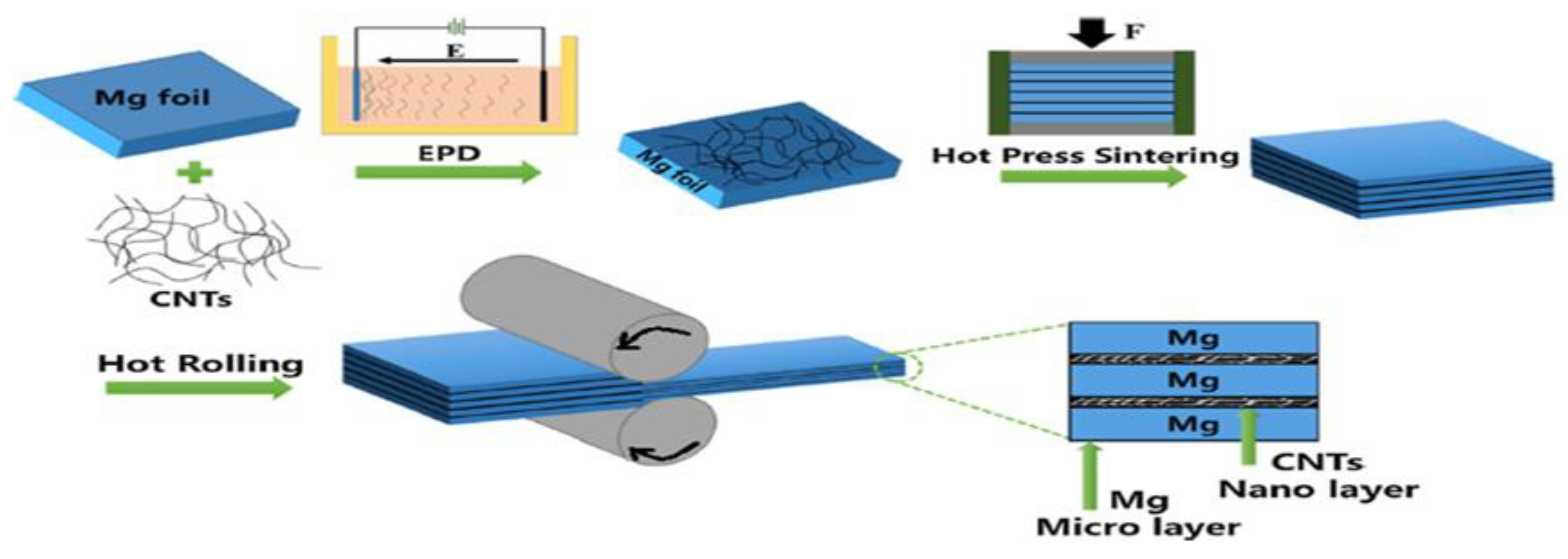
4.6. Spread Dispersion (SD)/Rolling Process

Spread dispersion/rolling process is an innovative route to fabricate Mg matrix composites by developing a layered micro-nano configuration. Xiang et al. [75] employed the SD/rolling process route to fabricate Mg/CNT-laminated composites. For obtaining the layered micro-nano configuration, they were the first to employ the method of electrophoretic deposition (EPD) for combining the CNTs with 50 µm Mg foils. The tests were oriented towards characteristic identification and revealed no clustering of the CNTs or proper dispersion of the CNT particles. They added that the characteristics of the layered configured composites can be customized by adopting variable thicknesses of Mg foils. Furthermore, the deposition time is the most important factor in deciding the thickness of the CNT layer. The process of fabrication ended with hot rolling of the stacked Mg foils, which resulted in the reduction in the total thickness by up to 60%. The researchers also investigated dislocation/slip vector movement in the fabricated composites; their observations and findings reported the presence of blockages in dislocation movement in the fabricated composite. The presence of these dislocation blockages resulted in a highly strengthened composite compared to the composites fabricated through conventional routes. Figure 5. illustrates the process route of fabrication of Mg/CNTs through the layered micro-nano configuration [75].

5. Mechanisms Responsible for Strengthening of Nano-Composites

The fabrication of metal matrix nanocomposites (MMNCs) through any of the routes mentioned above is commonly employed to enhance their mechanical characteristics, such as strength and stiffness, relative to the pure matrix material. These composite characteristics are accomplished by effectively transferring the working stress from the matrix material to the reinforcing agents, i.e., CNTs. Interfacial bonding of the CNTs and matrix material, homogenous dispersion of the CNTs in the matrix material, and aspect ratio are the chief deciding factors of the characteristics of a fabricated composite [110]. It has been observed that the observation of a crack at interfacial bonding between the reinforcement and matrix materials affects the composite’s toughness, and the ductility of the composite will be the factor of moderation of uttermost stresses near the interface [111]. Additionally, fabricated composites’ characteristics are highly altered through the process route employed in fabrication [11]. Four mechanisms have been suggested for understanding and gauging the strengthening effect in the fabricated composites, which are discussed further.

5.1. Load Transfer

Nardon and Prewo [112] have stated that the load transfer is the most acceptable mechanism. Following this mechanism, the interfacial bonding created in the fabricated composite enables the matrix material to transfer the applied stresses from the matrix material to the reinforcing agent. This will enhance the composite strength to bear the stresses. Although, for transferring the stresses and strengthening the composite, there should be an appropriate aspect ratio associated with the nano reinforcing materials [107,108,109,113,114,115]. Consequently, employing a reinforcing agent of greater hardness will be more effective in stress transfer and may strengthen the composite. The shear model [116] is widely accepted for analyzing the concept of load transfer mechanism. The perception made in the shear lag model is that a 3-D fiber will be considered as a 1-D object during the analysis. The shear model is also employed for analyzing the consequences of the presence of broken fiber in a metal matrix with various complexities [117]. Li P. et al. [118] conducted a study for developing AZ91D-based composites by introducing CNT-Mg2Sip as the reinforcing material through the in-situ process route. At the initial stage, the CNTs were oxidized through magnetic stirring in a 1:3 acidic mixture of concentrated H2SO4 and HNO3. The CNTs underwent acidic treatment with powdered AZ91D and were mechanically stirred in a C2H5OH solution for 2 h. The developed precipitated particles were dehydrated in a vacuum furnace at 60 °C for 10 h. These dehydrated particles and powdered Sip underwent ball milling in atmospheric shielding of Ar gas to develop 0.3 vol%CNTs-0.37 vol%Sip/AZ91D composite powders. This powdered CNT-Sip/Mg form was hot compacted at 200 °C in a vacuum environment. The compacted bar of the material was reheated in a capillary furnace at 585 °C for 60 min. Finally, the desired composite was developed by pouring the partial solid into a preheated mold under the pressure of 224 MPa. The same procedure was followed for the fabrication of 0.75 vol%CNTs-0.75 vol%Mg2Sip/AZ91D, 1.5 vol%CNTs/AZ91D, 1.5 vol%Mg2Sip/AZ91D and 3 vol%Mg2Sip/AZ91D. The results concluded that load transfer and thermal incongruity were the prime strengthening mechanisms in the developed composites. The most feasible mechanical characteristics among all the compositions fabricated were found for 0.3CNTs-1.2Mg2Sip/AZ91D.

5.2. Orowan Mechanism

Composite material undergoes plastic deformation beyond its yield limit. Plastic deformation of composites is due to crystallographic movement of dislocations; this plastic deformation consists of the Orowan mechanism [119]. The phenomenon of generation of residual dislocation loops near to the dispersed CNT particles in Mg matrix, occurs through the succeeding slip bends and sidestepping of the integrated agent’s incompliance with the Orowan mechanism. Thus, the generation of the residual loops consecutively strengthened the work material; hence, the dispersion of reinforcing agents in the metal matrix occurs in the developed composite [34,36,55,70,73,74,103]. Earlier studies have summarized that in order to analyze the Orowan mechanism in a fabricated composite, it is required to have interparticle spaces among the reinforcing agents. Additionally, it was concluded that appreciably strengthened composites were developed when cylindrically shaped reinforcing agents were incorporated instead of spherical ones [120]. For the composites that are fabricated through reinforcing the particles of comparatively smaller and shorter shapes, the Orowan mechanism plays a major role [121].

5.3. Thermal Incongruity

The thermal incongruity mechanism emerges when the generation of the enhanced dense dislocation site emerges around the reinforcing agents. This emergence is due to the appreciable variation in the coefficient of thermal expansion (CTE) between the reinforcing agent and matrix material. The presence of variation in CTE between the reinforcing agent and matrix causes the composite to undergo thermal changes, resulting in the generation of thermal and internal stresses. Due to the developed thermal variation, the dislocations are generated around the reinforcing agents to lower the stored energy. The dislocation density present in a composite is related to the thermal strain present in composites. These developed dislocations are the measuring parameters for the level of strengthening produced in the fabricated composites. Strengthening of the composite is enhanced with the enhancement in the density of dislocations [115,116,122]. Multiple strengthening mechanisms [60] due to the dispersion of CNTs in the metal matrix may be characterized according to the following equation:
σc = σmt + ∆σL + ∆σT + ∆σOrowan
In the above equation, σcm and σmt are the composite strength and matrix strengths, respectively, ∆σL, ∆σT, ∆σOrowan are the quantum enhancement in strength due to the mechanisms related to the transfer of the load, thermal incongruity, and Orowan.

5.4. Grain-Boundary Strengthening

Grain-boundary strengthening is also a member of the group of mechanisms that plays a chief role in strengthening the fabricated metal-based CNT-reinforced composites. Unlike all the other mechanisms mentioned above, the grain-boundary strengthening mechanism deals with the compressive strength of the composite. The mechanism is initiated through the refining of grains and results in enriched compressive strength of the composite. It has been experimentally observed that the grain-boundary strengthening befall during the composite development process routes involves refining the grain sizes [53,66,69,103,117]. It has also been observed that different process routes adopted to fabricate the CNT-reinforced composites result in dissimilar grain-boundary strengthening coefficients [123,124,125]. During the fabrication process of the composites, the reinforcing mechanism based on particle size is expected to occur by simple reinforcing principles based on stress transmission, such as “rule of mixture”. Compared to conventional reinforcing agents, such as SiC, the high aspect ratio property of CNTs enables the fabrication of the composite, which may contain minor voids to lock the dislocation movement, even with lower wt.% of the CNTs. The deformations through these composites are only possible if either the dislocation bypasses the hindrance created by the Orowan mechanism or with the shearing of CNTs. The characteristic feature of CNTs such as the smaller diameter and stress concentration at the head, contribute to the dislocation growth which results in the yielding.
Furthermore, a significant rise in resistance to creeping in the fabricated composite may be realized, as a result of the difficulty regarding the dislocation climb [126]. “Crack divergence”, “CNT’s linking” and “CNT’s bug-out” are the general Mg/CMT composite strengthening mechanisms. At the moment of failure in CNT-reinforced Mg-based composites, many CNTs pull out from the matrix. The pulling out of the CNTs lowers the crack propagation speed by overcoming the stresses at the crack tip. In addition, CNTs pulling out results in generated interfaces that require external work that must be carried out. Thus, crack propagation consumes surplus energy. When these bridged CNT composites are subjected to external stresses, the stresses generated on the crack surface are compressive. These compressive stresses develop near the crack surface, restricting further crack enhancement; consequently, the toughness of the composite rises. Xiang et al. [75] employed a layered micro-nano configuration to fabricate Mg/CNT composites. The study aimed to investigate the fractured format in fabricated Mg/CNT composites. Compared to pure Mg, in which a localized strain was observed, the fractured surface of the Mg/CNT composites was found to be smooth. The Mg/CNTs underwent advanced strain hardening and showed a substantial modification in even cleavage to a rough, jagged fractured surface. This progressive rate of strain hardening results in even more uniform deformation. CNT’s layers restrict the crack propagation; consequently, the CNT layers refine the toughness of the composite.

6. Mechanical Properties of Developed Composites Depending on the Production Process

Various studies have been carried out to investigate the mechanical properties concerned with fabricated Mg/CNT composites. The investigated mechanical properties obtained in Mg/CNT composites fabricated through different process routes are summarized in Table 1. Ding et al. [73] conducted an experiment to evaluate the mechanical characteristics related to Mg-based, CNT-reinforced composites fabricated through the powder metallurgy route. The fabrication process illustrated that the refinement of Mg powder could be achieved by ball milling before the dispersion of CNTs, which enabled CNTs to be uniformly dispersed in the matrix material. Furthermore, the sintering of Mg/CNTs was executed. The grain sizes of the sintered composite observed through optical microscopy were found to be approximately 2–25 µm. No considerable refinement in the grain size was observed in the sintered samples after ball milling (2–18 µm). The fabricated composite was further tested for the evaluation of mechanical properties. The results of these tests were concluded as follows: malleability of 11% was observed, compression strengths were found 504 MPa, and yield strengths were 454 MPa, respectively. Li et al. [35] developed Mg-MWCNT composites by employing a process route that consisted of two basic steps. The first step was executed for the pre-distribution of MWCNTs on matrix material Mg chips through a distributing block polymer. In a further step, the Mg chips containing the MWCNTs finely distributed on their surface were converted into molten form. This heating process of Mg chips was followed by stirring. Furthermore, this molten Mg alloy/MWCNT composite mix was solidified after it was poured into the mold. The sample analysis ensured that the addition of only 0.1 wt.% MWCNTs resulted in the outstanding rise of 36% in CYS and UCS. The investigators further concluded that the Mg matrix material’s deformability was enhanced due to thermal incongruity, load transfer, and Orowan strengthening mechanisms. In addition, they added that the CNT’s distribution in the base Mg matrix material effectively offered obstacles in crack propagation. Yuan et al. [71] initiated their study to evaluate the mechanical characteristics of the AZ91/CNT composites coated with MgO. Their experimental outcomes highlighted the enriched mechanical characteristics. The researchers concluded that the causes of enrichment were the Orowan mechanism, thermal mismatch, grain size modifications, and stress transfer mechanism. Zeng et al. [127] employed a manual stirring process route of distribution of MWCNTs in the AZ31 matrix. The MWCNTs that they utilized as reinforcing agents had 30 nm diameters and lengths of 1–10 µm. As an outcome of the experiment, they found extraordinary improvement in hardness, tensile strength, and Young’s modulus when the AZ31 matrices were loaded with 1 wt.% MWCNTs. They concluded that when the loading of MWCNTs rises from 1 wt.%, this resulted in the alteration of the tensile characteristics due to the development of clusters of MWCNTs in the AZ31 matrix. Hou et al. [55] developed MWCNT-reinforced Mg-9Al-based composites. Their experiment revealed the alterations in length from micron to nano size of the Mg17Al12 phase. During the study of Mg-9A/MWCNT composites, it was found that the addition of 0.4 wt.% of MWCNTs resulted in a UTS value of 355 MPa and elongation of 15%, which is represents 18% and 150% enhancement, respectively, compared to pure Mg. Proper dispersal of the nano-sized Mg17Al12 phase and appreciable inter-metallic bonding between the matrix and reinforcement were the responsible phenomena for the enhancement in the characteristics, according to the researchers. Goh et al. [31] employed the powder metallurgy route to develop Mg/MWCNT composites. For the MWCNTs, they adopted a diameter of 20 nm, and these reinforcing agents were added in different compositions from 0.06 to 0.3 wt.%. The fabrication proceeded by blending the MWCNTs and Mg powder, followed by sintering and hot extrusion. Regarding the study outcomes, they concluded that the addition of maximum wt.% in the adopted range, i.e., 0.3 wt.%, generated clusters in the matrix material.
Furthermore, they added that by increasing the wt.% of the CNTs, the yield strength and deformability of the composites rises. However, negligible impact was found on the composite’s UTS value by enhancing the wt.% of the CNTs. Shimizu et al. [95] carried out their study by fabricating AZ91D-based MWCNT-reinforced composites through the PM route. The route included ball mill, HPS, and extrusion processes. Their study was focused on refining the distribution of reinforcing MWCNT particles. They reported that the maximum yield strength (YS) and ultimate tensile strength (UTS) were observed with reinforcing 1 wt.% of the MWCNTs. They found proper distribution of the CNTs over the Mg matrix particles. Consequently, these generated restrictions in the deformations, and thus strengthened the composite material. Liu et al. [128] experimented with developing Mg-based composites reinforced with MWCNTs with a loading of 1.5 wt.%. The MWCNTs that they employed were 20–40 nm in diameter and 1–5 µm in length. The process route that they followed was mechanical stirring, with the incorporation of the high-intensity ultrasonic process. They reported that yield strength (YS), ultimate tensile strength (UTS) and elongation of the Mg matrix material were enriched by the dispersion of 1.5 wt.% MWCNTs as a reinforcing agent.
Sun, F. et al. [129] employed the CVD method to develop MWCNT-reinforced Mg-based composites. The CVD technique was performed at 480 °C by incorporating a Co/Mg catalyst and acetylene gas. The process was initiated with argon-shielded ball milling of the matrix material dispersed with MWCNTs in the range of 1.8, 2.4, and 3 wt.%, for 400 rpm for 2 h. The ball milled mixture was further sintered at 580 °C for 2 h and lastly extruded in a heated form. During observations, it was reported that the tensile strength of the matrix Mg was enhanced to 285 MPa with increments in the reinforcing agent up to 2.4 wt.%. This increment in tensile strength was about 45% of the pure Mg Matrix, which was 220 MPa. Increasing the composition of MWCNTs further up to 3 wt.% resulted in the clustering of the reinforcements. The matrix material Mg possesses HCP crystal geometry, which was the hindrance that Mg provided in tensile deformation. With the dispersion of MWCNTs and further extrusion, the prismatic and cross-slip dislocations vectors activated in the Mg matrix enhanced the composite’s deformability. Goh C.S. et al. [88,93] developed Mg/MWCNT composites by employing deposition of disintegrated melt and extrusion, incorporating variable wt.% reinforcing MWCNTs. In the study mentioned above, they concluded that with MWCNT incorporation of 0.3 and 1.3 wt.%, the tensile elongation, UTS and YS of the matrix material improved. Upon further increment of the reinforcement to 1.6 and 2 wt.%, the clustering of the MWCNTs was observed in the Mg matrix, and consequently reduced the tensile strength, deformability, and YS. It has also been reported that the fabrication of Mg/MWNCTs with MWCNTs consisting of length less than 100 µm, diameter of 20 nm and inferior loading lower than 1.3 wt.%, this resulted in the enhanced tensile deformability of the composites. The instigation of prismatic slipping and advancement in basal slipping resulted in this enhancement in deformability [97]. Figure 6 illustrates the CNTs that sheared and buckled under compressive loading. The shearing and buckling of the CNTs generated is due to the inhomogeneity of the tensile yield strength (TYS) or compressive yield strength CYS [105]. The buckling of CNTs occurs when these dispersed CNTs within the matrix material undergo fracture after experiencing compressive deformation.
Paramsothy, M. et al. [105] fabricated ZK60A matrix-based composites reinforced with CNTs of 40–70 nm outer diameter and an aspect ratio of about 100. They stated through their study that the dispersion of 1 vol.% of CNTs in the ZK60A matrix resulted in an improvement in UCS by about 5% and decrement in CYS of about 14%, compared to unreinforced ZK60A. With the same dispersion value of CNTs, the compressive strength (CS) of the developed composites was found to be inferior at any given strain value, compared with unreinforced ZK60A. Figure 6 illustrates the causes of this decrement in CS, which could be because of the adverse effects of (i) inferior intermetallic phase dilution in the fabricated composite or (ii) the phenomena of the generation of buckling in reinforced CNTs in the ZK60A matrix. The researchers have further stated that fabrication of the ZK60A/CNT composites was performed by employing CNTs with an aspect ratio of about 100. When the fabricated composites were subjected to compressive deformation, buckling of the CNTs was reported and consequently, they fractured within the matrix material [123,124,130,131]. The above-mentioned buckling in CNTs can also be carried out even more smoothly by enhancing the width to height ratio of the CNTs being used, which as a result lowers the limits of the characteristics concerning to reinforcement [100,125].
Table 1. Summarized investigated mechanical properties obtained in Mg/CNT composites fabricated through different process routes.
Sample(s)Fabrication Method(s)Young’s Modulus (GPa)Tensile ProprietiesCompressive PropertiesHardnessRef.
0.2%TYS (MPa)UTS (MPa)Elongation (%)CYS (MPa)UCS (MPa)Failure Strain (%)
Mg-1AlSPM + VS + HTEET:12.7 ± 0
EC:5.1 ± 0.2
156 ± 3201 ± 36.8 ± 0.4100 ± 3378 ± 717 ± 0.449 ± 3[29]
Mg-1Al-0.60 GNPsSPM + VS + HTEET: 17.1 ± 0.2
EC: 7.5 ± 0.6
202 ± 7263 ± 64.1 ± 0.7228 ± 4405 ± 412 ± 0.462 ± 3[29]
Mg-1Al-0.60 CNTsSPM + VS + HTEET: 15.5 ± 0.2
EC: 6.6 ± 0.3
211 ± 4286 ± 311 ± 0.2236 ± 3422 ± 312.3 ± 0.360 ± 6[29]
Mg-6Zn-0.5 CNTBM + ultrasonic treatment + SC 91193-----[30]
Mg-1Al-0.60 (1:5) (CNT + GNPs)SPM + VS + HTEET: 15.2 ± 0.3
EC: 6.8 ± 0.3
184 ± 5232 ± 516.1 ± 0.3166 ± 5398 ± 416 ± 0.357 ± 4[29]
Mg (98.5% purity)MBM + CP + HTE 126 ± 4203 ± 98 ± 1---47 ± 1[31]
Mg-0.06 CNTsMBM + CP + HTE 131 ± 3201 ± 313 ± 1---45 ± 1[31]
Mg-0.18 CNTsMBM + CP + HTE 136 ± 5204 ± 613 ± 2---47 ± 0[31]
Mg-0.30 CNTsMBM + CP + HTE 147 ± 4212 ± 57 ± 1---46 ± 1[31]
AZ91SI4.8 ± 282 ± 4204 ± 6----81[32]
AZ91-5 MWCNTsSI1.2 ± 2212 ± 11242 ± 9----151[32]
AZ91-5 (Si-MWCNTs)SI1.3 ± 2251 ± 11294 ± 9----159[32]
AZ91-0.1 MWCNTsSC----160 ± 4.741423.6 [35]
AZ31-0.1 MWCNTsSC + aged--------[36]
AZ31-0.5 MWCNTsSC + aged--------[36]
AZ31-1 MWCNTsSC + aged--------[36]
AZ31-1 CNTsBM + extrusion + welding 185 ± 5.7271 ± 7.37 ± 1.6 65 ± 3.5[37]
Mg-9AlSPM + HTE 234 ± 3300 ±45 ± 1 80.2 ± 2.6[55]
Mg-9Al-0.2 MWCNTsSPM + HTE 240 ± 3345 ± 315 ± 1 91.4 ± 1.8[55]
Mg-9Al 0.4 MWCNTsSPM + HTE 247 ± 4354 ± 614 ± 3 94.1 ± 2.6[55]
Mg-9Al-0.6 MWCNTsSPM + HTE 232 ± 3328 ± 212 ± 1 89.3 ± 4.7[55]
AZ31PM + extrusion 196 ± 5.1284 ± 2.814.4 ± 1.4161 ± 6.2361 ± 3.416.2 ± 1.659 ± 3.1[57]
AZ31-0.3 GNPPM + extrusion 172 ± 6.3274 ± 5.821.8 ± 2.7160 ± 4.6396 ± 5.416.1 ± 1.770 ± 2.3[57]
AZ31-0.3 CNTPM + extrusion 211 ± 2.7311 ± 5.213.2 ± 3.1241 ± 5.6458 ± 6.114.1 ± 1.279 ± 2.7[57]
Mg- 0.08 CNTsPM + PECS + HTE 18623716.2 [59]
AZ81DMD + HTE 2243357.7154 ± 16486 ± 1317.1 ± 0.2118 ± 2[62]
AZ81-1.5 CNTsDMD + HTE 27939112.7127 ± 18487 ± 1116.2 ± 1.6115 ± 7[62]
AZ91SPM + HTE 166 ± 5.0213 ± 6.06.8 ± 0.2 72.1 ± 2.0[71]
AZ91-1 CNTSPM + HTE 172 ± 4.2226 ± 5.28.4 ± 0.2 79.1 ± 2.1[71]
AZ91-2 CNTSPM + HTE 196 ± 4.4262 ± 5.48.6 ± 0.1 87.2 ± 1.6[71]
AZ91-3 CNTSPM + HTE 252 ± 3.6300 ± 4.49.2 ± 0.2 94.2 ± 2.1[71]
AZ91-4 CNTSPM + HTE 188 ± 3.4247 ± 3.88.4 ± 0.2 84.1 ± 1.7[71]
AZ91-5 CNTSPM + HTE 153 ± 4.6227 ± 5.57.6 ± 0.1 80.1 ± 1.6[71]
AZ91-1(MgO-CNT)SPM + HTE 191 ± 3.5261 ± 4.17.5 ± 0.2 80.1 ± 1.6[71]
AZ91-2(MgO-CNT)SPM + HTE 211 ± 5.1293 ± 6.18.1 ± 0.1 89.4 ± 1.1[71]
AZ91-3(MgO-CNT)SPM + HTE 283 ± 4.5330 ± 5.18.4 ± 0.2 96.3 ± 1.1[71]
AZ91-4(MgO-CNT)SPM + HTE 205 ± 3.6271 ± 4.78.1 ± 0.2 86.4 ± 1.1[71]
AZ91-5(MgO-CNT)SPM + HTE 174 ± 5.6254 ± 5.17.3 ± 0.1 83.4 ± 1.4[71]
MgPM + HTE 104 ± 09238 ± 1419.7 ± 1.642 ± 4[72]
Mg-0.5Al-0.18 CNTPM + HTE 121 ± 08356 ± 1311.1 ± 1.451 ± 3[72]
Mg-1Al-0.18 CNTPM + HTE 131 ± 03420 ± 1412.4 ± 1.257 ± 4[72]
Mg-1.50Al-0.18 CNTPM + HTE 142 ± 06420 ± 1011.1 ± 1.661 ± 3[72]
Pure MgBM + HPS 13716572.2 [73]
Mg-(Ni-CNTs)BM + HPS 0.4345350210.4503 [73]
Mg-0.05 CNT with 20% overall porosityPM 71.4 ± 19.3 [74]
Mg-0.05 CNT with 30% overall porosityPM 47 ±19 [74]
Mg-0.05 CNT with 40% overall porosityPM 19 ±9 [74]
Mg-1 CNT with 20% overall porosityPM 87.2 ± 25.7 [74]
Mg-1 CNT with 30% overall porosityPM 51.6 ± 19.4 [74]
Mg-1 CNT with 40% overall porosityPM 24.4 ± 10.6 [74]
Mg-0.05 CNTsEPD + HPS + HR 114 ± 4.1151 ± 4.64.7 ± 0.8 [75]
Mg-0.10 CNTsEPD + HPS + HR 142 ± 7.7173 ± 2.75.6 ± 0.8 [75]
Mg-2 wt.% CNTsBM + HPS38.7 ± 0.6871412 [78]
Mg-6Al-0.5 CNTMBM + CP + HTE ~161 ~41[96]
Mg-6Al-1 CNTMBM + CP + HTE ~141 ~37[96]
Mg-6Al-2 CNTMBM + CP + HTE ~106 ~35[96]
Mg-6Al-4 CNTMBM + CP + HTE ~77 ~27[96]
AZ91DSC 203263 73[102]
AZ91D-2 CNTSC 215.13288.22 78.48[102]
AZ91D-3 CNTSC 227.24295.46 82.77[102]
AZ91D-4 CNTSC 221.19292.36 91.87[102]
AZ91D-2 CNTSC 291.2 81.21[103]
AZ91D-3 CNTSC 301.457 86.92[103]
AZ91D-4 CNT 294.67 92.3[103]
ZK60ADMD 161 ± 3.2267 ± 26.7 ± 0.4126 ± 10521 ± 1019.4 ± 0.8138 ± 7[105]
ZK60A-1.0 CNTDMD 179 ± 5294 ± 715.2 ± 0.6111 ± 6544 ± 233.6 ± 6.4113 ± 7[105]
Mg-6ZnAs-cast 71 ± 3.4128 ± 2.58.2 ± 2.0 54 ± 5.9[109]
Mg-6ZnFSP 135 ± 4.7280 ± 4.118.8 ± 1.2 68 ± 3.7[109]
Mg-6Zn-1.0 CNTsMBM + SC + FSP 170 ± 2.1331 ± 5.415.1 ± 1.3 82 ± 7.1[109]
Mg (98.5% purity)BM + MS + HTE 125 ± 2172 ± 47.7 ± 0.2 37 ± 2[110]
Mg-0.3 CNTsBM + MS + HTE 117 ± 3161 ± 65.5 ± 0.3 35 ± 2[110]
Mg-0.3 (Ni-CNTs)BM + MS + HTE 205 ± 3236 ± 26.3 ± 0.2 53 ± 2[110]
Mg-3Al-1ZnSPM44.214824715.22 47.33 ± 3.4[132]
Mg-3Al-1Zn -0.5 CNTsSPM50.116126815.93 57.31 ± 4.4[132]
Mg-3Al-1Zn -1.0 CNTsSPM55.318529521.58 60.35 ± 2.1[132]
Mg-3Al-1Zn -1.5 CNTsSPM52.317726121.38 60.87 ± 3.2[132]
Li et al. [68] employed CNTs with diameters of 40–60 nm and lengths of 2 µm to fabricate Mg/CNT composites. It was observed through the testing that the CNTs’ distributions were dependent on the degree of solidification. Through the observations, they stated that with an inferior degree of solidification, CNTs were found to be projected out of the solidification front and clustered besides the gain boundaries. Furthermore, at a higher degree of solidification, appreciable CNT-matrix interface bonding was observed, resulted in improved UTS and YS of the fabricated composite. Park et al. [32] fabricated composites using AZ91 matrix material reinforced through Si-coated MWCNTs with diameters of 5–10 nm and lengths of 0.5–10 µm.
The microstructural study depicted the formation of a uniform structure and consequently, the mechanical characteristics of the fabricated AZ91-based composite reinforced with MWCNTs were improved. Nai et al. [110] employed Ni coating on reinforced CNTs with the diametric specification of 10–20 nm for fabricating composites in Mg matrices. The generation of Mg2Ni intermetallic phases in the fabricated composite was observed as the consequence of employing Ni coating on CNTs, which resulted in the improved distribution of CNTs (Ni coated) and strengthening of the linkages was observed between the CNTs and matrix. Conclusively, they stated that the mechanical characteristics, such as micro-hardness, universal tensile strength, and yield strength, of the fabricated composite were improved by 41%, 39%, and 64%, respectively, compared to the unreinforced Mg material. Corrosion resistivity in composite material is also a major issue, which has attracted the focus of various researchers to investigate that area of study. The studies discussed above did not focus on the resistance offered by the fabricated composites to corrosion. In a further section of this article, the consequences of the dispersion of CNTs on the corrosion behavior of Mg matrix material are discussed.

7. Corrosion Properties

Magnesium is a prime material used in automotive, aerospace, and medical lightweight applications. Nevertheless, the low corrosion resistivity of magnesium material provides hurdles regarding its adaptability in various other applications, and this also degrades the life cycle of the servicing period. Several studies have been conducted so far regarding the enhancement of the mechanical characteristics of developed composites [88,91,93]. However, no such in-depth studies have been conducted yet for observing the corrosion characteristics. The tendency of Mg to become easily corrosive in various environments is due to the development of a substandard magnesium oxide or magnesium hydroxide layer of low ordinary electrode voltage (−2.36 V) [130,131,132]. The MMCs fabricated by incorporating the particulate reinforcements of ceramics or carbon fibers are found to have low anti-corrosive properties, when subjected to environments containing chloride ions. These chloride ions affect the matrix and the reinforcing material interfaces, leading to fissure and pitting corrosion [133]. It has been also observed that the rate of corrosion on Mg-based MMCs was found to be enhanced due to the presence of Cu [134], Al2O3 [135], Mo [130] and SiC [131] reinforcing materials. Corrosion behavior of MMCs composed of CNTs as reinforcing agents lies in their matrix material, along with the process route adopted for their fabrication. In the case of Mg as a matrix material, it has been observed that the presence of CNTs as reinforcing material enhances the corrosion behavior [63,130,131]. This enhancement in corrosion behavior is due to the formation of galvanic couples between the reinforcing material CNTs and the matrix material Mg, resulting from their large in-between variation in standard electrode potentials. Additionally, it has been observed that the presence of intermetallic phases, such as β-Mg17Al12, Al–Mn and Al–Mn–Fe in Mg alloys, behaves as cathode terminals to promote micro-galvanic corrosion at the anodic Mg-based matrix [88,132,133,134,135,136,137,138,139]. As CNTs possesses high electrode potential, their reinforcement in Mg to develop composites, also enhances the galvanic corrosion in developed MMCs.c8
The electrical characteristics of CNTs are diverse in comparison to other carbon allotropes. Because of this, the behavior of Mg matrix material could be divergent when reinforced with CNTs [11]. Endo et al. [79] proposed that the rate of corrosion could be reduced by separating the oxide layers from the Mg matrix by MWCNTs, which leads to decelerating the corrosive layer formation. The researchers examined a pure AZ91D Mg alloy, fabricated AZ91D/CNT composites in salt water, and observed the development of rigid oxide layers at the Mg-alloy matrix material grain boundaries. They concluded that surface protective layers were found to be reinforced through CNTs and possess water shielding characteristics. The researchers in their investigation did not report on the relevance of galvanic corrosion between Mg and CNTs; additionally, it was not clearly explained if development of the oxide layers could boost the overall anti-corrosive nature of the Mg matrix. The rate of corrosion of MMCs could be degraded by developing passive layers on the fabricated composite surfaces [11]. Furthermore, the study performed to fabricate Mg/CNT composites did not revealed the development of such passive behavior in inhibiting further corrosion [140,141,142,143,144,145]. The microstructural study of fabricated Mg/CNT composites revealed that a major percentage of CNTs were stacked near to primary particle boundary, the fabricated composite’s surface was locally damaged and severe galvanic corrosion occurred in the CNT’s vicinity [136,137]. Fukuda et al. [66] fabricated an AZ31B Mg alloy-based MMC, by incorporating the MWCNTs as the reinforcing agents through the PECS route. To study the corrosion characteristics of the fabricated composites, the researchers performed an immersion and polarization test by subjecting it to NACL. Because of the appreciable amount of the potential difference between the matrix and reinforcing material in the NACL solution, similar conditions to the galvanic cell were developed. Furthermore, the anticorrosive characteristics of AZ31B degraded due to the large number of corrosive byproducts stacked in the CNTs’ vicinity. The pH value of the solution in which the fabricated composites were dipped was enhanced comparatively to the AZ31B pure alloy. Monolithic Mg underwent progressive chemical reactions with aqueous solutions and these are as follows [138,139,140,146,147]:
2H2O + 2e → H2 + 2OH
Mg →Mg2+ + 2e
Mg2+ + 2OH → Mg(OH)2
Mg(OH)2 was not developed adequately enough to restrict the further corrosion of the fabricated composites in a corrosive environment. According to the above-mentioned reactions, the magnesium fusion enhances the solution’s pH value. Furthermore, the Mg(OH)2 layer could be converted into MgCl2 salt due to the presence of Cl ions, resulting in an increment in Mg dissolution according to the following chemical reaction:
Mg + 2Cl → MgCl2
Aung et al. [65] developed Mg-based CNT-reinforced composites and subjected them to NACL solution in order to observe the corrosive characteristics through the mass loss due to the immersion test, hydrogen evolution measurement, and polarization curves. It was reported that the corrosive characteristics of the fabricated composites were enhanced, as compared to unreinforced Mg. The reason for this enhancement is the development of intermediate corrosion, sandwiched between Mg and CNTs of galvanic nature. Saikrishna N. et al. [148] conducted experimental work to develop Mg/MWCNT composites through FSP. Unadulterated 10 mm thick Mg sheets of size 100 × 80 × 10 mm3 were prepared for the process. Before execution of the FSP process, dual zig-zag blind holes in multiple rows were developed on the Mg plates to fill with the MWCNTs. To prevent the reinforcing particles from ejecting out from the holes, a pin-less FSP tool with a revolving speed of 1400 rpm and a travel speed of 25 mm/min was adopted to execute the process. Sample investigations concluded that the presence of CNTs improved the micro-hardness of the fabricated composite relative to unadulterated Mg. However, the fabricated composites’ corrosion behavior was sacrificed, leading to enhanced galvanic corrosion. Turhan et al. [137], Aung et al. [65], and Li et al. [138] also concluded in their studies that reinforcing the Mg matrix with CNTs results in lower anticorrosive strength of the fabricated composites, due to the generation of galvanic couples. Table 2 depicts the corrosion characteristics of the fabricated Mg/CNT composites. Funatsu et al. [149] attempted to examine the corrosion behavior of developed AZ61B-based CNT-reinforced composites through the PM route. In the experimentation, they employed thermal treatment of 823 K for the duration of 10 h while introducing Al atoms into the fabricated composites, resulting in an accumulation of Al atoms adjacent to the CNTs’ surface. The presence of Al atoms in CNTs’ vicinity was reported to lower the potential difference between the matrix and reinforced material. The researchers further performed an immersion test on the fabricated composite to examine the effect on the corrosion rate by immersion in NACL solution and reported that the rate was lowered down to 30% of the composite in which Al atoms were not introduced. Say Y. et al. [150] fabricated AZ61 and AZ91 matrix material-based composites by introducing CVD’s prepared CNTs as the reinforcing agent through the PM process route. For producing the CNTs through CVD, the substrate used was p-type Si wafer. Before preparing the substrate, the furnace capillary was washed 5 times in a vacuum of 10-3 Torr and further heated along with Ar gas. The developed CNTs in 0.1, 0.2 and 0.5 wt.% were added with a predefined exact ratio of powdered matrix material and ethanol solution. This mix was further ball milled at 200 rpm for a duration of 90 min. The prepared ball milled mixture was compacted in die of 12 mm diameter at 500 MPa and sintered at 500 °C for 2 h. Characteristic identification concluded that the increments of wt.% of the CNTs sacrificed the strength of the fabricated composite in both matrix materials. The corrosion resistive capability of the fabricated composites with higher wt.% CNTs was also found to be degraded, as compared to 0.1 and 0.2 wt.%. For both matrix alloys, the highest corrosive currents were reported for the samples containing 0.5 wt.% of CNT. Aydin et al. [93] fabricated Mg/MWCNT composites through the PM route and performed plasma electrolytic oxidation (PEO) to develop the coating on the fabricated composites. Furthermore, they examined the fabricated composites through potential-dynamic corrosion tests. They reported that the corrosion rate of the coated material decreased by 1.6 times that of the uncoated composite. Davaari M. et al. [151] studied the corrosion behavior of the fabricated AZ31B-H24 Mg alloy-based composite reinforced with PEO/PCL-coated MWCNTs. Initially, the specimens of the base material of 15 mm × 15 mm × 2.5 mm were prepared and microstructural study was performed after polishing and etching. A jacketed electrochemical cell with continuous electrolyte stirring adoption was adopted for the PEO coating for 10 min with enforced voltage amplitudes of + 405/ −25 V for 60 s and output current density restricted to 100 mA/cm2. Similarly, the PEO process was also performed for 5 g/L of MWCNTs containing electrolytes. The counter electrode employed for the process was a cylindrical mesh of SS 316. The coated specimens were cleaned with water and isopropanol and dehydrated in lukewarm airflow. For detecting the uncoated, PEO coated and PEO-MWCNTs, the employed acronyms were BM, PEO and PCT, respectively. PEO and PCT were sealed using either a thinner or dual PCL layer. Investigations concluded that thrusting pitting corrosion in the PEO samples was due to successively generated stress, agglomeration of the corrosive byproducts and undercoating corrosion. The PCT coating developed on the samples delayed the undercoating corrosion by 48 h. Sealing of the PCL layer resulted in appreciable enhancement of the corrosive resistive strength by 15%, in comparison to PCT.

8. Wear and Friction Properties

Mg-based composites have been recognized as one of the prime selections among the lightweight materials, with applications in aerospace, automotive, and biomedical fields. The superior properties of Mg, such as the ability to reprocess, appreciable damp character, treatable machinability, good electromagnetic shielding, and plenteousness, makes Mg an adequate selection among all the other materials. However, the specific properties of Mg that make it an inferior choice for tribological applications include remarkably low hardness and wear resistance. The hardness and wear resistivity of the Mg-based composites can be altered according to the fabrication route that is adopted for their fabrication, even though the coefficient of friction and wear resistivity of the fabricated composites may be enhanced by introducing ceramic as the reinforcing agent in the Mg matrix [11]. It has been reported that composites composed of Mg matrix and CNTs as reinforcing agents have commendable self-lubricating and mechanical characteristics, low coefficient of friction, and high wear resistance [11,143,144,145,154,155]. Recently, CNTs have emerged as an attractive reinforcing material that can be used for reinforcing Mg. Numerous investigations have been performed to examine the effect of CNTs on composites regarding their mechanical and corrosion properties. Additionally, some studies have been conducted to evaluate the wear characteristics of Mg-CNT nanocomposites.
Jamshidijam et al. [108] developed metal matrix composites by adding the MWCNT reinforcement into AZ31 Mg matrix material through the FSP route. They conducted a relative study between reinforced and unreinforced MMCs on their respective wear resistive capabilities. As a result, they reported an outstanding improvement in mechanical characteristics in MMCs due to the presence of MWCNTs as a reinforcing agent. They argued that this improvement occurred due to the grain’s structural improvement, appreciable interfacial bonding between AZ31 and MWCNTs, and uniform dispersion of the reinforcing particles in the matrix material. Selvamani et al. [103] employed a stir casting fabrication route to fabricate AZ91D-based composites reinforced with CNTs. The MMCs were reinforced by loading 2, 3, and 4 wt.% of CNTs in order to examine the changes in the mechanical properties of the developed composites. They reported that the MMC samples that contained 3 wt.% showed extraordinary wear resistive nature, compared to unreinforced AZ91D. In addition to the mentioned phenomena, they experienced enhancement in the tensile strength of the same 3 wt.% sample, which was verified by their ductile mode facture. They reported extraordinary hardness values with further enhancement of the wt.% of the CNTs up to 4. Mindivan et al. [96] argued that uneven fragments and dragged out CNTs from fabricated Mg6Al-CNTs at the matrix–reinforcement interface could enhance the lubricating behavior. They also concluded that even high wt.% CNT loading may result in inferior wear resistive characteristics, if unsatisfactory interfacial linking is present among the chip layers.
Abbas et al. [36] fabricated AZ31-based composites reinforced with MWCNTs through the stir casting route, which was further processed through precipitation hardening for the duration of 10 h. The study was focused on examining the wear characteristics of the fabricated composites. The results of the respective study were graphically depicted in the form of bars, designated for the loss of mass and coefficient of friction, in contradiction to the increasing values of wt.% of the CNTs, as shown in Figure 7. Conclusively, the researchers argued that increments in the CNT wt.% decreased the wear-out weight loss of the composites. The researchers also stated that two factors were responsible for this decrement in weight loss. First, the increment in wt.% in CNTs enhanced the strength and hardness. Second, the self-lubricating characteristic of CNTs, which lowered the coefficient of friction, led to material loss. Abbas A. et al. [36] performed a study to reveal the wear characteristics of fabricated AZ31-CNT composites. In order to reveal the effects of CNTs on the fabricated composites and their wear behavior, CNTs were introduced in different wt.% in the AZ31 matrix. The manufactured composite part’s worn-out surfaces were studied through scanning electron microscopy (SEM) to obtain knowledge related to their erosion, oxidation, abrasion and permanent deformation patterns. Figure 8. depicts the worn-out surfaces of the SEM micrographs in non-wet sliding conditions.
Figure 8a depicts the SEM micrograph of the fabricated composites comprising 1 wt.% of CNTs. The micrograph clearly highlights the plenteous worn-out depression as well as the marks; most of them are tending towards the sliding direction. This abrasive nature of these wt.% CNTs raised due to clustering of the CNTs, which performed as plowing agent in the fabricated composites for promoting abrasion. As a result, the clustered zone of CNTs promoted to occur the phenomenon of 3-body abrasion. According to the 3-body abrasion phenomenon, a hard element stuck between two surfaces could lead to abrasion of one or both surfaces [108]. The 3-body abrasion could happen along with the wear-out and abrasion phenomenon [156]. Figure 8b depicts the micrograph of the fabricated composites comprising CNTs of 0.5 wt.%. The wear-out characteristics pertaining to oxidation could be read using the micrograph. The wear-out characteristics of the composites are highly affected by the thickness of the oxidation layer that developed. It has been reported that the wear rate of the composites was lowered due to the presence of a thicker oxidation layer, which prevents the surfaces from sliding, and hence consecutively generated an inferior wear environment [157]. Figure 8c depicts the SEM micrograph of the fabricated composite containing 0.5 wt.% of CNTs. Generated networks of major voids that developed on the wear-out surface can be easily observed from the micrograph. These major voids are the leftovers of shearing of the surface through the propagation of cracks, generated by the application of dynamic forces. The wear characteristics were also revealed by the heating of the surfaces that they are in contact with. This heating could lead the asperities to become soft, restricting them from adhering to the counterpart surface. The repeated continuous sliding motion enabled the asperities to gather at the contact surface, which led to nucleation, resulting in the erosion of the contact surfaces in a layered form. This type of wear mechanism, which is initiated without the generation of wear cracks damages, the surfaces more severely and is known as plastic wear. Figure 8d. depicts the SEM micrograph of the unreinforced AZ31 matrix material. The significance of the plastic wear can be observed through the micrograph. At elevated loading conditions, these layered wear characteristics become responsible for permanent deformation of the surfaces [158]. The tendency of the wear-out mechanism is to support permanent deformation, enhanced in the conditions of high surface roughness [159]. This permanent deformation phenomenon was forced to occur through the heat generation between the counter steel plate and fabricated composite sample and consequently, the permanent distortion of the surface is enabled towards the direction of sliding [160]. It has been observed that large uneven irregularities separated from part were deformed severely and extruded towards the sliding direction [36]. The anti-wear characteristics and the coefficient of friction of the fabricated composites was drastically enhanced through the presence of CNTs in their vicinity. Most of the studies performed so far that concern the wear characteristics of the fabricated composites have revealed the behavioral effect on the composites through different compositions of CNTs, but one must obtain more knowledge in order to establish the association of wear behavior of fabricated composites to their respective CNT loading.

9. Conclusions

The current article highlights the reputations of the factors that influence the conventional routes for fabricating Mg-based composites reinforced with CNTs, their potential, challenges, and scope for future developments. Their exclusive optical, electrical, thermal, and mechanical characteristics, as well as their enhanced surface area and aspect ratio, make CNTs a superior candidate for reinforcing metal matrices as a way of enriching their properties, such as self-lubrication characteristics, overall lightweight nature, and superior strength. These enriched properties in the fabricated composites could be achieved if the fabrication process could allocate the reinforcing agent uniformly. Throughout the article, knowledge has been gathered on the significance of several factors that play a role in various Mg/CNTs fabrication routes, along with various strengthening mechanisms, corrosion behavior, and wear properties and the following conclusions are suggested:
  • Due to various obstacles in the fabrication route of CNT-reinforced metal matrix composites (MMCs), inadequate studies have been accomplished in the mentioned domain. Only the fabrication routes pertaining to PM and stirring casting have been comprehensively studied.
  • The mechanical characteristics of fabricated Mg/CNT-reinforced composites that have been debated and observed demonstrate that they are broadly altered through the process route adopted to fabricate the composites. Additionally, uniform allocation of CNTs, specifications concerned with CNTs, wt.% of CNTs in matrix material, CNTs’ orientation with matrix material and their in-between interfacial bonding could be the responsible factors for enhancing the mechanical characteristics by an appreciable amount.
  • With regard to enhancing the strength of the composites to bear stresses, the load transfer mechanism is expected to happen at the interfaces of the Mg matrix and CNTs in fabricated composites. As a result, the composite will enable the transfer of the stresses to reinforce CNTs more adequately. The interfacial bonding is crucial due to poor wettability between CNTs and the Mg matrix, which arises due to their considerable surface tension difference. This difference in the surface tension prevents the Mg matrix material from being coated with CNTs. This interfacial bonding could be strengthened by enhancing the wettability by incorporating Cu, Ni, or Cr as the coating material for CNTs.
  • The mechanism through which the composites were reinforced with CNTs in the Mg matrix that undergoes corrosion is the micro-scale galvanic phenomenon in sodium chloride solution. The CNTs present in the Mg matrix behaved appreciably as cathodes; as a result, increasing the wt.% of CNTs in the Mg matrix could decrease the corrosion resistivity of the fabricated composite.
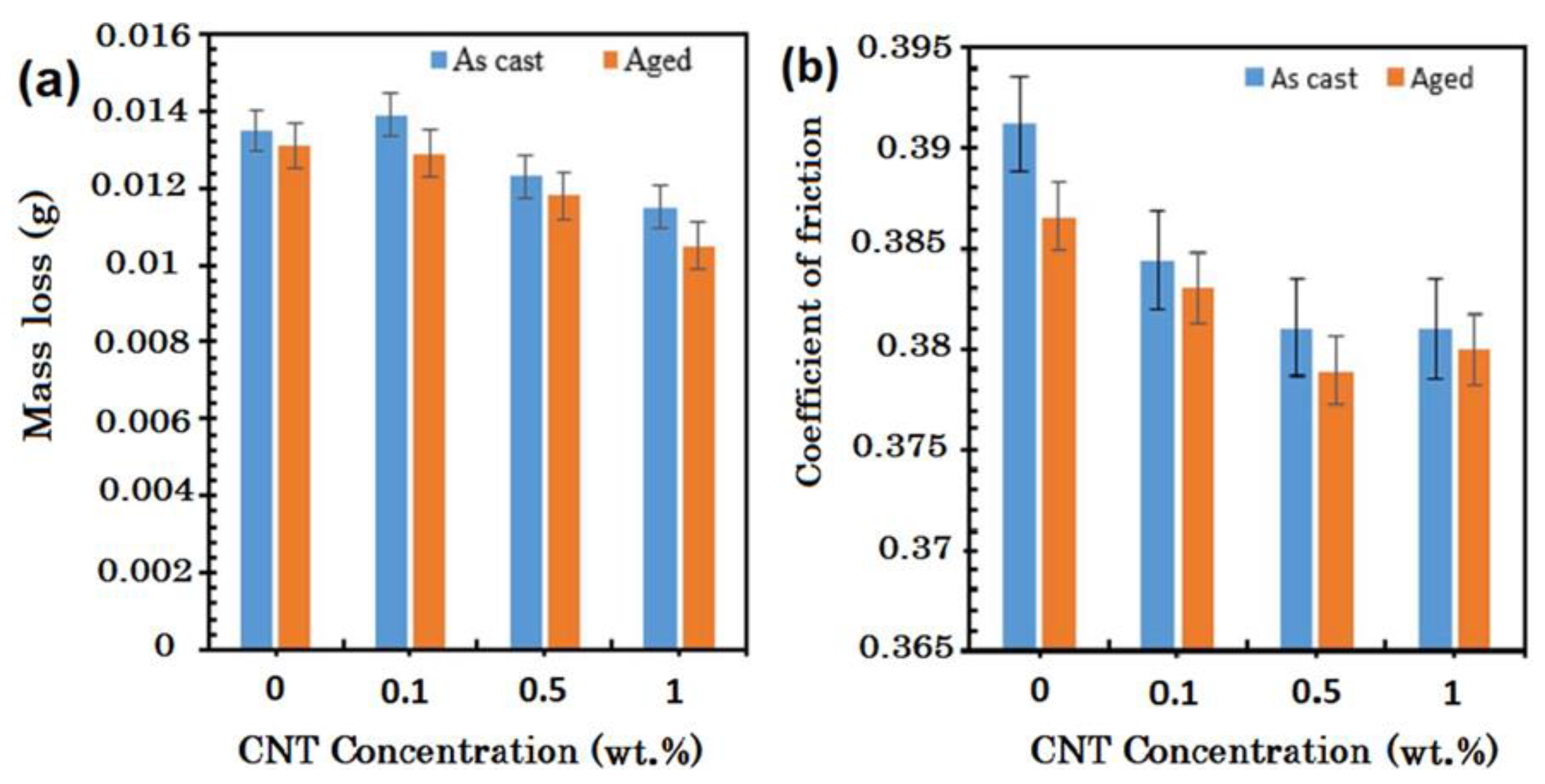
  • The coefficient of friction and wear resistivity of the fabricated composites could be altered according to the fabrication route adopted for fabricating them. Incorporating increased wt.% of CNTs in the Mg matrix could lead to enhanced self-lubrication characteristics, refined mechanical characteristics, low coefficient of friction, and high wear resistance.

Author Contributions

Conceptualization, G.U. and K.K.S.; methodology, S.S.; formal analysis, K.A.M.; writing—original draft preparation, G.U.; writing—review and editing, C.P., S.D.; supervision, D.B. All authors have read and agreed to the published version of the manuscript.

Funding

This research was funded by Ministry of Science and Higher Education of the Russian Federation as part of the World-class Research Center program: Advanced Digital Technologies: contract No. 075-15-2022-311 dated 20 April 2022.

Institutional Review Board Statement

Not applicable.

Informed Consent Statement

Not applicable.

Data Availability Statement

Not applicable.

Conflicts of Interest

No conflict of interest among all authors.

References

  1. Ali, Y.; Qiu, D.; Jiang, B.; Pan, F.; Zhang, M.X. Current research progress in grain refinement of cast magnesium alloys: A review article. J. Alloys Compd. 2015, 619, 639–651. [Google Scholar] [CrossRef]
  2. Saberi, A.; Bakhsheshi-Rad, H.R.; Karamian, E.; Kasiri-Asgarani, M.; Ghomi, H. Magnesium-graphene nano-platelet composites: Corrosion behavior, mechanical and biological properties. J. Alloys Compd. 2020, 821, 153379. [Google Scholar] [CrossRef]
  3. Chai, F.; Zhang, D.; Zhang, W.; Li, Y. Microstructure evolution during high strain rate tensile deformation of a fine-grained AZ91 magnesium alloy. Mater. Sci. Eng. A 2014, 590, 80–87. [Google Scholar] [CrossRef]
  4. Pollock, T.M. Weight Loss with Magnesium Alloys. Science 2010, 328, 985–986. [Google Scholar] [CrossRef]
  5. Barnett, M.R.; Ghaderi, A.; da Fonseca, J.Q.; Robson, J.D. Influence of orientation on twin nucleation and growth at low strains in a magnesium alloy. Acta Mater. 2014, 80, 380–391. [Google Scholar] [CrossRef]
  6. Zhang, L.; Liu, C.G.; Wang, H.Y.; Nan, X.L.; Liu, G.J.; Jiang, Q.C. Slip-induced texture evolution of rolled Mg–6Al–3Sn alloy during uniaxial tension along rolling and transverse directions. Mater. Sci. Eng. A 2014, 597, 376–380. [Google Scholar] [CrossRef]
  7. Wang, Q.; Liu, K.; Wang, Z.; Li, S.; Du, W. Microstructure, texture and mechanical properties of as-extruded Mg–Zn–Er alloys containing W-phase. J. Alloys Compd. 2014, 602, 32–39. [Google Scholar] [CrossRef]
  8. Allen, M.J.; Tung, V.C.; Kaner, R.B. Honeycomb carbon: A review of graphene. Chem. Rev. 2010, 110, 132–145. [Google Scholar] [CrossRef]
  9. Artiles, M.S.; Rout, C.S.; Fisher, T.S. Graphene-based hybrid materials and devices for biosensing. Adv. Drug Deliv. Rev. 2011, 63, 1352–1360. [Google Scholar] [CrossRef]
  10. Thostenson, E.T.; Ren, Z.; Chou, T.W. Advances in the science and technology of carbon nanotubes and their composites: A review. Compos. Sci. Technol. 2001, 61, 1899–1912. [Google Scholar] [CrossRef] [Green Version]
  11. Tjong, S.C. Recent progress in the development and properties of novel metal matrix nanocomposites reinforced with carbon nanotubes and graphene nanosheets. Mater. Sci. Eng. R Rep. 2013, 74, 281–350. [Google Scholar] [CrossRef]
  12. Shahin, M.; Munir, K.; Wen, C.; Li, Y. Magnesium matrix nanocomposites for orthopedic applications: A review from mechanical, corrosion, and biological perspectives. Acta Biomater. 2019, 96, 1–19. [Google Scholar] [CrossRef]
  13. Manchado, M.A.L.; Valentini, L.; Biagiotti, J.; Kenny, J.M. Thermal and mechanical properties of single-walled carbon nanotubes–polypropylene composites prepared by melt processing. Carbon 2005, 43, 1499–1505. [Google Scholar] [CrossRef]
  14. Bakshi, S.R.; Lahiri, D.; Agarwal, A. Carbon nanotube reinforced metal matrix composites—A review. Int. Mater. Rev. 2010, 55, 41–64. [Google Scholar] [CrossRef]
  15. Radhamani, A.V.; Lau, H.C.; Ramakrishna, S. CNT-reinforced metal and steel nanocomposites: A comprehensive assessment of progress and future directions. Compos. Part A Appl. Sci. Manuf. 2018, 114, 170–187. [Google Scholar] [CrossRef]
  16. Yu, F.; Wang, Y.; Liu, Y.; Hui, H.Y.; Wang, F.X.; Li, J.F.; Wang, Q. An aqueous rechargeable zinc-ion battery on basis of an organic pigment. Rare Met. 2022, 41, 2230–2236. [Google Scholar] [CrossRef]
  17. Fan, W.; Zhang, L.; Liu, T. Graphene-CNT Hybrids for Energy Applications. In Graphene-Carbon Nanotube Hybrids for Energy and Environmental Applications; Springer: Singapore, 2017; pp. 53–90. [Google Scholar] [CrossRef]
  18. de Vita, A.; Charlier, J.-C.; Blase, X.; Car, R. Electronic structure at carbon nanotube tips. Appl. Phys. A Mater. Sci. Process. 1999, 68, 283–286. [Google Scholar] [CrossRef]
  19. Popov, V.N. Carbon nanotubes: Properties and application. Mater. Sci. Eng. R: Rep. 2004, 43, 61–102. [Google Scholar] [CrossRef]
  20. Kuche, K.; Maheshwari, R.; Tambe, V.; Mak, K.K.; Jogi, H.; Raval, N.; Pichika, M.R.; Tekade, R.K. Carbon nanotubes (CNTs) based advanced dermal therapeutics: Current trends and future potential. Nanoscale 2018, 10, 8911–8937. [Google Scholar] [CrossRef]
  21. Zhao, X.; Song, B.; Fan, W.; Zhang, Y.; Shi, Y. Selective laser melting of carbon/AlSi10Mg composites: Microstructure, mechanical and electronical properties. J. Alloys Compd. 2016, 665, 271–281. [Google Scholar] [CrossRef]
  22. Huang, Y.; Ouyang, Q.; Zhang, D.; Zhu, J.; Li, R.; Yu, H. Carbon materials reinforced aluminum composites: A review. Acta Metall. Sin. 2014, 27, 775–786. [Google Scholar] [CrossRef]
  23. Singh, A.; Prabhu, T.R.; Sanjay, A.R.; Koti, V. An Overview of Processing and Properties of CU/CNT Nano Composites. Mater. Today Proc. 2017, 4, 3872–3881. [Google Scholar] [CrossRef]
  24. Mittal, G.; Dhand, V.; Rhee, K.Y.; Park, S.J.; Lee, W.R. A review on carbon nanotubes and graphene as fillers in reinforced polymer nanocomposites. J. Ind. Eng. Chem. 2015, 21, 11–25. [Google Scholar] [CrossRef]
  25. Cha, S.I.; Kim, K.T.; Arshad, S.N.; Mo, C.B.; Hong, S.H. Extraordinary strengthening effect of carbon nanotubes in metal-matrix nanocomposites processed by molecular-level mixing. Adv. Mater. 2005, 17, 1377–1381. [Google Scholar] [CrossRef]
  26. Prusty, R.K.; Rathore, D.K.; Ray, B.C. CNT/polymer interface in polymeric composites and its sensitivity study at different environments. Adv. Colloid Interface Sci. 2017, 240, 77–106. [Google Scholar] [CrossRef] [PubMed]
  27. Neubauer, E.; Kitzmantel, M.; Hulman, M.; Angerer, P. Potential and challenges of metal-matrix-composites reinforced with carbon nanofibers and carbon nanotubes. Compos. Sci. Technol. 2010, 70, 2228–2236. [Google Scholar] [CrossRef] [Green Version]
  28. Moghadam, A.D.; Omrani, E.; Menezes, P.L.; Rohatgi, P.K. Mechanical and tribological properties of self-lubricating metal matrix nanocomposites reinforced by carbon nanotubes (CNTs) and graphene—A review. Compos. Part B Eng. 2015, 77, 402–420. [Google Scholar] [CrossRef]
  29. Rashad, M.; Pan, F.; Tang, A.; Asif, M.; Aamir, M. Synergetic effect of graphene nanoplatelets (GNPs) and multi-walled carbon nanotube (MW-CNTs) on mechanical properties of pure magnesium. J. Alloys Compd. 2014, 603, 111–118. [Google Scholar] [CrossRef]
  30. Shi, H.; Wang, X.; Li, C.; Hu, X.; Ding, C.; Wu, K.; Huang, Y. A novel method to fabricate CNT/Mg-6Zn composites with high strengthening efficiency. Acta Metall. Sin. 2014, 27, 909–917. [Google Scholar] [CrossRef]
  31. Goh, C.S.; Wei, J.; Lee, L.C.; Gupta, M. Development of novel carbon nanotube reinforced magnesium nanocomposites using the powder metallurgy technique. Nanotechnology 2006, 17, 7–12. [Google Scholar] [CrossRef]
  32. Park, Y.; Cho, K.; Park, I.; Park, Y. Fabrication and mechanical properties of magnesium matrix composite reinforced with Si coated carbon nanotubes. Procedia Eng. 2011, 10, 1446–1450. [Google Scholar] [CrossRef] [Green Version]
  33. Morisada, Y.; Fujii, H.; Nagaoka, T.; Fukusumi, M. MWCNTs/AZ31 surface composites fabricated by friction stir processing. Mater. Sci. Eng. A 2006, 419, 344–348. [Google Scholar] [CrossRef]
  34. Moghadam, A.D.; Schultz, B.F.; Ferguson, J.B.; Omrani, E.; Rohatgi, P.K.; Gupta, N. Functional metal matrix composites: Self-lubricating, self-healing, nanocomposites-an outlook. JOM 2014, 66, 872–881. [Google Scholar] [CrossRef]
  35. Li, Q.; Viereckl, A.; Rottmair, C.A.; Singer, R.F. Improved processing of carbon nanotube/magnesium alloy composites. Compos. Sci. Technol. 2009, 69, 1193–1199. [Google Scholar] [CrossRef]
  36. Abbas, A.; Huang, S.J.; Ballóková, B.; Sülleiová, K. Tribological effects of carbon nanotubes on magnesium alloy AZ31 and analyzing aging effects on CNTs/AZ31 composites fabricated by stir casting process. Tribol. Int. 2020, 142, 105982. [Google Scholar] [CrossRef]
  37. Sabetghadam-Isfahani, A.; Abbasi, M.; Sharifi, S.M.H.; Fattahi, M.; Amirkhanlou, S.; Fattahi, Y. Microstructure and mechanical properties of carbon nanotubes/AZ31 magnesium composite gas tungsten arc welding filler rods fabricated by powder metallurgy. Diam. Relat. Mater. 2016, 69, 160–165. [Google Scholar] [CrossRef]
  38. Ferguson, J.B.; Sheykh-Jaberi, F.; Kim, C.S.; Rohatgi, P.K.; Cho, K. On the strength and strain to failure in particle-reinforced magnesium metal-matrix nanocomposites (Mg MMNCs). Mater. Sci. Eng. A 2012, 558, 193–204. [Google Scholar] [CrossRef]
  39. Nanostructured & Amorphous Materials, Inc. (NanoAmor). Available online: https://nanoamor.com/ (accessed on 4 October 2020).
  40. Lijima, S. Helical microtubules of graphitic carbon. Nature 1991, 354, 56–58. [Google Scholar]
  41. Hashimoto, S.; Iwamoto, T.; Kurachi, D.; Kayahara, E.; Yamago, S. Shortest Double-Walled Carbon Nanotubes Composed of Cycloparaphenylenes. Chempluschem 2017, 82, 1015–1020. [Google Scholar] [CrossRef] [Green Version]
  42. Lijima, S.; Lchihashi, T. Single-shell carbon nanotubes of 1-nm diameter. Nature 1993, 363, 603–605. [Google Scholar] [CrossRef] [Green Version]
  43. Liu, Z.; Tabakman, S.; Welsher, K.; Dai, H. Carbon nanotubes in biology and medicine: In vitro and in vivo detection, imaging and drug delivery. Nano Res. 2009, 2, 85–120. [Google Scholar] [CrossRef] [PubMed] [Green Version]
  44. Guo, J.; Zhang, Q.; Gao, L.; Zhong, W.; Sui, G.; Yang, X. Significantly improved electrical and interlaminar mechanical properties of carbon fiber laminated composites by using special carbon nanotube pre-dispersion mixture. Compos. Part A Appl. Sci. Manuf. 2017, 95, 294–303. [Google Scholar] [CrossRef]
  45. Hu, D.; Xing, Y.; Chen, M.; Gu, B.; Sun, B.; Li, Q. Ultrastrong and excellent dynamic mechanical properties of carbon nanotube composites. Compos. Sci. Technol. 2017, 141, 137–144. [Google Scholar] [CrossRef] [Green Version]
  46. Kumar, S.; Rani, R.; Dilbaghi, N.; Tankeshwar, K.; Kim, K.H. Carbon nanotubes: A novel material for multifaceted applications in human healthcare. Chem. Soc. Rev. 2017, 46, 158–196. [Google Scholar] [CrossRef] [PubMed]
  47. O’connell, M.J. Carbon Nanotubes: Properties and Applications; CRC Press: Boca Raton, FL, USA, 2006. [Google Scholar]
  48. Dong, Z.; Jiang, C.; Cheng, H.; Zhao, Y.; Shi, G.; Jiang, L.; Qu, L. Facile fabrication of light, flexible and multifunctional graphene fibers. Adv. Mater. 2012, 24, 1856–1861. [Google Scholar] [CrossRef]
  49. Ruoff, R.S.; Qian, D.; Liu, W.K. Mechanical properties of carbon nanotubes: Theoretical predictions and experimental measurements. Comptes Rendus Phys. 2003, 4, 993–1008. [Google Scholar] [CrossRef]
  50. Abazari, S.; Shamsipur, A.; Bakhsheshi-Rad, H.R.; Ismail, A.F.; Sharif, S.; Razzaghi, M.; Ramakrishna, S.; Berto, F. Carbon nanotubes (CNTs)-reinforced magnesium-based matrix composites: A comprehensive review. Materials 2020, 13, 4421. [Google Scholar] [CrossRef]
  51. Yu, Y.P. Preparation, purification and properties of carbon nanotubes. Adv. Mater. Res. 2012, 557–559, 472–477. [Google Scholar] [CrossRef]
  52. Terrones, M. Carbon nanotubes: Synthesis and properties, electronic devices and other emerging applications. Int. Mater. Rev. 2004, 49, 325–377. [Google Scholar] [CrossRef]
  53. Yang, S.; Yu, S.; Cho, M. Influence of Thrower–Stone–Wales defects on the interfacial properties of carbon nanotube/polypropylene composites by a molecular dynamics approach. Carbon 2013, 55, 133–143. [Google Scholar] [CrossRef]
  54. Ying, L.S.; Salleh, M.A.b.M.; Yusoff, H.B.M.; Rashid, S.B.A.; Razak, J.B.A. Continuous production of carbon nanotubes—A review. J. Ind. Eng. Chem. 2011, 17, 367–376. [Google Scholar] [CrossRef]
  55. Hou, J.; Du, W.; Parande, G.; Gupta, M.; Li, S. Significantly enhancing the strength + ductility combination of Mg-9Al alloy using multi-walled carbon nanotubes. J. Alloys Compd. 2019, 790, 974–982. [Google Scholar] [CrossRef]
  56. Wang, Q.; Du, W.; Liu, K.; Wang, Z.; Li, S.; Wen, K. Microstructure, texture and mechanical properties of as-extruded Mg–Zn–Er alloys. Mater. Sci. Eng. A 2013, 581, 31–38. [Google Scholar] [CrossRef]
  57. Rashad, M.; Pan, F.; Zhang, J.; Asif, M. Use of high energy ball milling to study the role of graphene nanoplatelets and carbon nanotubes reinforced magnesium alloy. J. Alloys Compd. 2015, 646, 223–232. [Google Scholar] [CrossRef]
  58. Rashad, M.; Pan, F.; Asif, M. Exploring mechanical behavior of Mg–6Zn alloy reinforced with graphene nanoplatelets. Mater. Sci. Eng. A 2016, 649, 263–269. [Google Scholar] [CrossRef]
  59. Han, G.Q.; Shen, J.H.; Ye, X.X.; Chen, B.; Imai, H.; Kondoh, K.; Du, W.B. The influence of CNTs on the microstructure and ductility of CNT/Mg composites. Mater. Lett. 2016, 181, 300–304. [Google Scholar] [CrossRef]
  60. Bakshi, S.R.; Agarwal, A. An analysis of the factors affecting strengthening in carbon nanotube reinforced aluminum composites. Carbon 2011, 49, 533–544. [Google Scholar] [CrossRef]
  61. Han, G.; Wang, Z.; Liu, K.; Li, S.; Du, X.; Du, W. Synthesis of CNT-reinforced AZ31 magnesium alloy composites with uniformly distributed CNTs. Mater. Sci. Eng. A 2015, 628, 350–357. [Google Scholar] [CrossRef]
  62. Paramsothy, M.; Tan, X.H.; Chan, J.; Kwok, R.; Gupta, M. Carbon nanotube addition to concentrated magnesium alloy AZ81: Enhanced ductility with occasional significant increase in strength. Mater. Des. 2013, 45, 15–23. [Google Scholar] [CrossRef]
  63. Fukuda, H.; Kondoh, K.; Umeda, J.; Fugetsu, B. Interfacial analysis between Mg matrix and carbon nanotubes in Mg–6 wt.% Al alloy matrix composites reinforced with carbon nanotubes. Compos. Sci. Technol. 2011, 71, 705–709. [Google Scholar] [CrossRef]
  64. Ghali, E.; Dietzel, W.; Kainer, K.U. General and Localized Corrosion of Magnesium Alloys: A Critical Review. J. Mater. Eng. Perform. 2004, 13, 7–23. [Google Scholar] [CrossRef]
  65. Aung, N.N.; Zhou, W.; Goh, C.S.; Nai, S.M.L.; Wei, J. Effect of carbon nanotubes on corrosion of Mg–CNT composites. Corros. Sci. 2010, 52, 1551–1553. [Google Scholar] [CrossRef]
  66. Fukuda, H.; Szpunar, J.A.; Kondoh, K.; Chromik, R. The influence of carbon nanotubes on the corrosion behaviour of AZ31B magnesium alloy. Corros. Sci. 2010, 52, 3917–3923. [Google Scholar] [CrossRef]
  67. Stansbury, E.E.; Buchanan, R.A. Fundamentals of Electrochemical Corrosion; ASM International: Novelty, OH, USA, 2000; ISBN 1615030670. [Google Scholar]
  68. Li, C.D.; Wang, X.J.; Liu, W.Q.; Shi, H.L.; Ding, C.; Hu, X.S.; Zheng, M.Y.; Wu, K. Effect of solidification on microstructures and mechanical properties of carbon nanotubes reinforced magnesium matrix composite. Mater. Des. 2014, 58, 204–208. [Google Scholar] [CrossRef]
  69. Honma, T.; Nagai, K.; Katou, A.; Arai, K.; Suganuma, M.; Kamado, S. Synthesis of high-strength magnesium alloy composites reinforced with Si-coated carbon nanofibres. Scr. Mater. 2009, 60, 451–454. [Google Scholar] [CrossRef]
  70. Liang, J.; Li, H.; Qi, L.; Tian, W.; Li, X.; Zhou, J.; Wang, D.; Wei, J. Influence of Ni-CNTs additions on the microstructure and mechanical properties of extruded Mg-9Al alloy. Mater. Sci. Eng. A 2016, 678, 101–109. [Google Scholar] [CrossRef]
  71. Yuan, Q.-H.; Zeng, X.-S.; Liu, Y.; Luo, L.; Wu, J.-B.; Wang, Y.-C.; Zhou, G.-H. Microstructure and mechanical properties of AZ91 alloy reinforced by carbon nanotubes coated with MgO. Carbon 2016, 96, 843–855. [Google Scholar] [CrossRef]
  72. Habibi, M.K.; Paramsothy, M.; Hamouda, A.M.S.; Gupta, M. Enhanced compressive response of hybrid Mg-CNT nano-composites. J. Mater. Sci. 2011, 46, 4588–4597. [Google Scholar] [CrossRef]
  73. Yuan, Q.H.; Zeng, X.S.; Liu, Y.; Luo, L.; Wu, J.B.; Wang, Y.C.; Zhou, G.H. High performance carbon nanotube-reinforced magnesium nanocomposite. Mater. Sci. Eng. A 2020, 771, 138575. [Google Scholar] [CrossRef]
  74. Zou, N.; Li, Q. Compressive mechanical property of porous magnesium composites reinforced by carbon nanotubes. J. Mater. Sci. 2016, 51, 5232–5239. [Google Scholar] [CrossRef]
  75. Xiang, Y.; Wang, X.; Hu, X.; Meng, L.; Song, Z.; Li, X.; Sun, Z.; Zhang, Q.; Wu, K. Achieving ultra-high strengthening and toughening efficiency in carbon nanotubes/magnesium composites via constructing micro-nano layered structure. Compos. Part A Appl. Sci. Manuf. 2019, 119, 225–234. [Google Scholar] [CrossRef]
  76. Li, Q.; Tian, B. Compression behavior of magnesium/carbon nanotube composites. J. Mater. Res. 2013, 28, 1877–1884. [Google Scholar] [CrossRef]
  77. Thornby, J.; Harris, A.; Bird, A.; Beake, B.; Manakari, V.; Gupta, M.; Haghshenas, M. Micromechanics and indentation creep of magnesium carbon nanotube nanocomposites: 298 K–573 K. Mater. Sci. Eng. A 2021, 801, 140418. [Google Scholar] [CrossRef]
  78. Carreño-Morelli, E.; Yang, J.; Couteau, E.; Hernadi, K.; Seo, J.W.; Bonjour, C.; Schaller, R. Carbon nanotube/magnesium composites. Phys. Status Solidi Appl. Res. 2004, 201, R53–R55. [Google Scholar] [CrossRef]
  79. Endo, M.; Hayashi, T.; Itoh, I.; Kim, Y.A.; Shimamoto, D.; Muramatsu, H.; Shimizu, Y.; Morimoto, S.; Terrones, M.; Iinou, S.; et al. An anticorrosive magnesium/carbon nanotube composite. Appl. Phys. Lett. 2008, 92, 063105. [Google Scholar] [CrossRef] [Green Version]
  80. Fukuda, H.; Kondoh, K.; Umeda, J.; Fugetsu, B. Fabrication of magnesium based composites reinforced with carbon nanotubes having superior mechanical properties. Mater. Chem. Phys. 2011, 127, 451–458. [Google Scholar] [CrossRef]
  81. Hulbert, D.M.; Anders, A.; Andersson, J.; Lavernia, E.J.; Mukherjee, A.K. A discussion on the absence of plasma in spark plasma sintering. Scr. Mater. 2009, 60, 835–838. [Google Scholar] [CrossRef]
  82. Rashad, M.; Pan, F.; Asif, M.; Tang, A. Powder metallurgy of Mg–1%Al–1%Sn alloy reinforced with low content of graphene nanoplatelets (GNPs). J. Ind. Eng. Chem. 2014, 20, 4250–4255. [Google Scholar] [CrossRef]
  83. Kondoh, K.; Fukuda, H.; Umeda, J.; Imai, H.; Fugetsu, B.; Endo, M. Microstructural and mechanical analysis of carbon nanotube reinforced magnesium alloy powder composites. Mater. Sci. Eng. A 2010, 527, 4103–4108. [Google Scholar] [CrossRef]
  84. Suslick, K.S.; Hammerton, D.A.; Cline, R.E. Sonochemical Hot Spot; McGraw-Hill: New York, NY, USA, 1986. [Google Scholar]
  85. Abazari, S.; Shamsipur, A.; Bakhsheshi-Rad, H.R.; Berto, F. Functionalized carbon nanotube-encapsulated magnesium-based nanocomposites with outstanding mechanical and biological properties as load-bearing bone implants. Mater. Des. 2022, 213, 110354. [Google Scholar] [CrossRef]
  86. Matsuda, T.; Minami, D.; Khoerunnisa, F.; Sunaga, M.; Nakamura, M.; Utsumi, S.; Itoh, T.; Fujimori, T.; Hayashi, T.; Hattori, Y.; et al. Aqueous Nanosilica Dispersants for Carbon Nanotube. Langmuir 2015, 31, 3194–3202. [Google Scholar] [CrossRef] [PubMed]
  87. O’Connell, M.J.; Bachilo, S.M.; Huffman, C.B.; Moore, V.C.; Strano, M.S.; Haroz, E.H.; Rialon, K.L.; Boul, P.J.; Noon, W.H.; Kittrell, C.; et al. Band gap fluorescence from individual single-walled carbon nanotubes. Science 2002, 297, 593–596. [Google Scholar] [CrossRef] [PubMed] [Green Version]
  88. di Crescenzo, A.; Cambré, S.; Germani, R.; di Profio, P.; Fontana, A. Dispersion of SWCNTs with imidazolium-rich surfactants. Langmuir 2014, 30, 3979–3987. [Google Scholar] [CrossRef] [PubMed]
  89. Liu, Y.; Yu, L.; Zhang, S.; Yuan, J.; Shi, L.; Zheng, L. Dispersion of multiwalled carbon nanotubes by ionic liquid-type Gemini imidazolium surfactants in aqueous solution. Colloids Surf. A Physicochem. Eng. Asp. 2010, 359, 66–70. [Google Scholar] [CrossRef]
  90. Chen, L.; Xie, H. Properties of carbon nanotube nanofluids stabilized by cationic gemini surfactant. Thermochim. Acta 2010, 506, 62–66. [Google Scholar] [CrossRef]
  91. Hou, J.; Du, W.; Meng, F.; Zhao, C.; Du, X. Effective dispersion of multi-walled carbon nanotubes in aqueous solution using an ionic-gemini dispersant. J. Colloid Interface Sci. 2018, 512, 750–757. [Google Scholar] [CrossRef]
  92. Goh, C.S.; Wei, J.; Lee, L.C.; Gupta, M. Simultaneous enhancement in strength and ductility by reinforcing magnesium with carbon nanotubes. Mater. Sci. Eng. A 2006, 423, 153–156. [Google Scholar] [CrossRef]
  93. Aydin, F.; Ayday, A.; Turan, M.E.; Zengin, H. Role of graphene additive on wear and electrochemical corrosion behaviour of plasma electrolytic oxidation (PEO) coatings on Mg–MWCNT nanocomposite. Surf. Eng. 2020, 36, 791–799. [Google Scholar] [CrossRef]
  94. Kumar, H.P.; Xavior, M.A. Graphene Reinforced Metal Matrix Composite (GRMMC): A Review. Procedia Eng. 2014, 97, 1033–1040. [Google Scholar] [CrossRef] [Green Version]
  95. Shimizu, Y.; Miki, S.; Soga, T.; Itoh, I.; Todoroki, H.; Hosono, T.; Sakaki, K.; Hayashi, T.; Kim, Y.; Endo, M.; et al. Multi-walled carbon nanotube-reinforced magnesium alloy composites. Scr. Mater. 2008, 58, 267–270. [Google Scholar] [CrossRef] [Green Version]
  96. Mindivan, H.; Efe, A.; Kosatepe, A.H.; Kayali, E.S. Fabrication and characterization of carbon nanotube reinforced magnesium matrix composites. Appl. Surf. Sci. 2014, 318, 234–243. [Google Scholar] [CrossRef]
  97. Goh, C.S.; Wei, J.; Lee, L.C.; Gupta, M. Ductility improvement and fatigue studies in Mg-CNT nanocomposites. Compos. Sci. Technol. 2008, 68, 1432–1439. [Google Scholar] [CrossRef]
  98. Li, Q.; Rottmair, C.A.; Singer, R.F. CNT reinforced light metal composites produced by melt stirring and by high pressure die casting. Compos. Sci. Technol. 2010, 70, 2242–2247. [Google Scholar] [CrossRef] [Green Version]
  99. Gupta, M.; Sharon, N.M.L. Magnesium, Magnesium Alloys, Magnesium Composites; John Wiley & Sons: Hoboken, NJ, USA, 2011; ISBN 1118102703. [Google Scholar]
  100. Tun, K.S.; Gupta, M. Improving mechanical properties of magnesium using nano-yttria reinforcement and microwave assisted powder metallurgy method. Compos. Sci. Technol. 2007, 67, 2657–2664. [Google Scholar] [CrossRef]
  101. Sherif, E.-S.M.; Latief, F.H.; Junaedi, H.; Almajid, A.A. Influence of Exfoliated Graphite Nanoplatelets Particles Additions and Sintering Temperature on the Mechanical Properties of Aluminum Matrix Composites. Int. J. Electrochem. Sci. 2012, 7, 4352–4361. [Google Scholar]
  102. Kumar, S.P.; Selvamani, S.T.; Vigneshwar, M.; Hariharan, S.J. Tensile, Microhardness, and Microstructural Analysis on Mg-CNT Nano Composites. Mater. Today Proc. 2018, 5, 7882–7888. [Google Scholar] [CrossRef]
  103. Selvamani, S.T.; Premkumar, S.; Vigneshwar, M.; Hariprasath, P.; Palanikumar, K. Influence of carbon nano tubes on mechanical, metallurgical and tribological behavior of magnesium nanocomposites. J. Magnes. Alloy. 2017, 5, 326–335. [Google Scholar] [CrossRef]
  104. Yuan, Q.H.; Liao, L.; Zhou, G.H.; Liu, Z.Y. ZM1 magnesium alloy reinforced by carbon nanotubes using an improved casting process. Rare Met. 2021, 40, 1275–1283. [Google Scholar] [CrossRef]
  105. Paramsothy, M.; Chan, J.; Kwok, R.; Gupta, M. Addition of CNTs to enhance tensile/compressive response of magnesium alloy ZK60A. Compos. Part A Appl. Sci. Manuf. 2011, 42, 180–188. [Google Scholar] [CrossRef]
  106. Mishra, R.S.; Ma, Z.Y. Friction stir welding and processing. Mater. Sci. Eng. R Rep. 2005, 50, 1–78. [Google Scholar] [CrossRef]
  107. Sharma, S.; Handa, A.; Singh, S.S.; Verma, D. Influence of tool rotation speeds on mechanical and morphological properties of friction stir processed nano hybrid composite of MWCNT-Graphene-AZ31 magnesium. J. Magnes. Alloy. 2019, 7, 487–500. [Google Scholar] [CrossRef]
  108. Jamshidijam, M.; Akbari-Fakhrabadi, A.; Masoudpanah, S.M.; Hasani, G.H.; Mangalaraja, R.v. Wear Behavior of Multiwalled Carbon Nanotube/AZ31 Composite Obtained by Friction Stir Processing. Tribol. Trans. 2013, 56, 827–832. [Google Scholar] [CrossRef]
  109. Huang, Y.; Li, J.; Wan, L.; Meng, X.; Xie, Y. Strengthening and toughening mechanisms of CNTs/Mg-6Zn composites via friction stir processing. Mater. Sci. Eng. A 2018, 732, 205–211. [Google Scholar] [CrossRef]
  110. Nai, M.H.; Wei, J.; Gupta, M. Interface tailoring to enhance mechanical properties of carbon nanotube reinforced magnesium composites. Mater. Des. 2014, 60, 490–495. [Google Scholar] [CrossRef]
  111. Clyne, T.W.; Withers, P.J. An Introduction to Metal Matrix Composites; Cambridge University Press: Cambridge, UK, 1995; ISBN 0521483573. [Google Scholar]
  112. Nardone, V.C.; Prewo, K.M. On the strength of discontinuous silicon carbide reinforced aluminum composites. Scr. Metall. 1986, 20, 43–48. [Google Scholar] [CrossRef]
  113. Chen, B.; Shen, J.; Ye, X.; Jia, L.; Li, S.; Umeda, J.; Takahashi, M.; Kondoh, K. Length effect of carbon nanotubes on the strengthening mechanisms in metal matrix composites. Acta Mater. 2017, 140, 317–325. [Google Scholar] [CrossRef]
  114. Chen, B.; Shen, J.; Ye, X.; Imai, H.; Umeda, J.; Takahashi, M.; Kondoh, K. Solid-state interfacial reaction and load transfer efficiency in carbon nanotubes (CNTs)-reinforced aluminum matrix composites. Carbon 2017, 114, 198–208. [Google Scholar] [CrossRef]
  115. Chen, B.; Li, S.; Imai, H.; Jia, L.; Umeda, J.; Takahashi, M.; Kondoh, K. Load transfer strengthening in carbon nanotubes reinforced metal matrix composites via in-situ tensile tests. Compos. Sci. Technol. 2015, 113, 1–8. [Google Scholar] [CrossRef]
  116. Xiang, S.; Wang, X.; Gupta, M.; Wu, K.; Hu, X.; Zheng, M. Graphene nanoplatelets induced heterogeneous bimodal structural magnesium matrix composites with enhanced mechanical properties. Sci. Rep. 2016, 6, 38824. [Google Scholar] [CrossRef]
  117. Landis, C.M.; McMeeking, R.M. A shear-lag model for a broken fiber embedded in a composite with a ductile matrix. Compos. Sci. Technol. 1999, 59, 447–457. [Google Scholar] [CrossRef]
  118. Li, P.; Tan, W.; Gao, M.; Shi, K. Strengthening of the magnesium matrix composites hybrid reinforced by chemically oxidized carbon nanotubes and in situ Mg2Sip. J. Alloys Compd. 2021, 858, 158673. [Google Scholar] [CrossRef]
  119. Park, J.G.; Keum, D.H.; Lee, Y.H. Strengthening mechanisms in carbon nanotube-reinforced aluminum composites. Carbon 2015, 95, 690–698. [Google Scholar] [CrossRef]
  120. Mirza, F.A.; Chen, D.L. A unified model for the prediction of yield strength in particulate-reinforced metal matrix nanocomposites. Materials 2015, 8, 5138–5153. [Google Scholar] [CrossRef] [PubMed] [Green Version]
  121. Ma, P.; Jia, Y.; Gokuldoss, P.K.; Yu, Z.; Yang, S.; Zhao, J.; Li, C. Effect of Al2O3 nanoparticles as reinforcement on the tensile behavior of Al-12Si composites. Metals 2017, 7, 359. [Google Scholar] [CrossRef] [Green Version]
  122. Li, J.; Liu, B.; Fang, Q.H.; Huang, Z.W.; Liu, Y.W. Atomic-scale strengthening mechanism of dislocation-obstacle interaction in silicon carbide particle-reinforced copper matrix nanocomposites. Ceram. Int. 2017, 43, 3839–3846. [Google Scholar] [CrossRef]
  123. Zhao, X.; Lu, C.; Tieu, A.K.; Pei, L.; Zhang, L.; Cheng, K.; Huang, M. Strengthening mechanisms and dislocation processes in <111> textured nanotwinned copper. Mater. Sci. Eng. A 2016, 676, 474–486. [Google Scholar] [CrossRef]
  124. Kim, K.T.; Eckert, J.; Menzel, S.B.; Gemming, T.; Hong, S.H. Grain refinement assisted strengthening of carbon nanotube reinforced copper matrix nanocomposites. Appl. Phys. Lett. 2008, 92, 12. [Google Scholar] [CrossRef] [Green Version]
  125. Wang, F.-C.; Zhang, Z.-H.; Sun, Y.-J.; Liu, Y.; Hu, Z.-Y.; Wang, H.; Korznikov, A.V.; Korznikova, E.; Liu, Z.-F.; Osamu, S. Rapid and low temperature spark plasma sintering synthesis of novel carbon nanotube reinforced titanium matrix composites. Carbon 2015, 95, 396–407. [Google Scholar] [CrossRef]
  126. George, R.; Kashyap, K.T.; Rahul, R.; Yamdagni, S. Strengthening in carbon nanotube/aluminium (CNT/Al) composites. Scr. Mater. 2005, 53, 1159–1163. [Google Scholar] [CrossRef]
  127. Zeng, X.; Zhou, G.H.; Xu, Q.; Xiong, Y.; Luo, C.; Wu, J. A new technique for dispersion of carbon nanotube in a metal melt. Mater. Sci. Eng. A 2010, 527, 5335–5340. [Google Scholar] [CrossRef]
  128. Liu, S.Y.; Gao, F.P.; Zhang, Q.Y.; Zhu, X.; Li, W.Z. Fabrication of carbon nanotubes reinforced AZ91D composites by ultrasonic processing. Trans. Nonferrous Met. Soc. China 2010, 20, 1222–1227. [Google Scholar] [CrossRef]
  129. Sun, F.; Shi, C.; Rhee, K.Y.; Zhao, N. In situ synthesis of CNTs in Mg powder at low temperature for fabricating reinforced Mg composites. J. Alloys Compd. 2013, 551, 496–501. [Google Scholar] [CrossRef]
  130. Thostenson, E.T.; Chou, T.W. Nanotube buckling in aligned multi-wall carbon nanotube composites. Carbon 2004, 42, 3015–3018. [Google Scholar] [CrossRef]
  131. Namilae, S.; Chandra, N. Role of atomic scale interfaces in the compressive behavior of carbon nanotubes in composites. Compos. Sci. Technol. 2006, 66, 2030–2038. [Google Scholar] [CrossRef] [Green Version]
  132. Wu, L.; Wu, R.; Hou, L.; Zhang, J.; Sun, J.; Zhang, M. Microstructure and Mechanical Properties of CNT-Reinforced AZ31 Matrix Composites Prepared Using Hot-Press Sintering. J. Mater. Eng. Perform. 2017, 26, 5495–5500. [Google Scholar] [CrossRef]
  133. Hamdy, A.S.; Alfosail, F.; Gasem, Z. Electrochemical behavior of a discontinuously A6092/SiC/17.5p metal matrix composite in chloride containing solution. Electrochim. Acta 2013, 88, 129–134. [Google Scholar] [CrossRef]
  134. Abhijeet, S.B.; Balasubramaniam, R.; Gupta, M. Corrosion behaviour of Mg–Cu and Mg–Mo composites in 3.5% NaCl. Corros. Sci. 2008, 50, 2423–2428. [Google Scholar] [CrossRef]
  135. Bakkar, A.; Neubert, V. Corrosion characterisation of alumina–magnesium metal matrix composites. Corros. Sci. 2007, 49, 1110–1130. [Google Scholar] [CrossRef]
  136. Tiwari, S.; Balasubramaniam, R.; Gupta, M. Corrosion behavior of SiC reinforced magnesium composites. Corros. Sci. 2007, 49, 711–725. [Google Scholar] [CrossRef]
  137. Turhan, M.C.; Li, Q.; Jha, H.; Singer, R.F.; Virtanen, S. Corrosion behaviour of multiwall carbon nanotube/magnesium composites in 3.5% NaCl. Electrochim. Acta 2011, 56, 7141–7148. [Google Scholar] [CrossRef]
  138. Li, Q.; Turhan, M.C.; Rottmair, C.A.; Singer, R.F.; Virtanen, S. Influence of MWCNT dispersion on corrosion behaviour of their Mg composites. Mater. Corros. 2012, 63, 384–387. [Google Scholar] [CrossRef]
  139. Aung, N.N.; Zhou, W. Effect of grain size and twins on corrosion behaviour of AZ31B magnesium alloy. Corros. Sci. 2010, 52, 589–594. [Google Scholar] [CrossRef]
  140. Zhou, W.; Aung, N.N.; Sun, Y. Effect of antimony, bismuth and calcium addition on corrosion and electrochemical behaviour of AZ91 magnesium alloy. Corros. Sci. 2009, 51, 403–408. [Google Scholar] [CrossRef]
  141. Aung, N.N.; Zhou, W. Effect of heat treatment on corrosion and electrochemical behaviour of AZ91D magnesium alloy. J. Appl. Electrochem. 2002, 32, 1397–1401. [Google Scholar] [CrossRef]
  142. Shi, J.; Ming, J.; Sun, W. Passivation and chloride-induced corrosion of a duplex alloy steel in alkali-activated slag extract solutions. Constr. Build. Mater. 2017, 155, 992–1002. [Google Scholar] [CrossRef]
  143. Jia, J.X.; Atrens, A.; Song, G.; Muster, T.H. Simulation of galvanic corrosion of magnesium coupled to a steel fastener in NaCI solution. Mater. Corros. 2005, 56, 468–474. [Google Scholar] [CrossRef]
  144. Andreatta, F.; Apachitei, I.; Kodentsov, A.A.; Dzwonczyk, J.; Duszczyk, J. Volta potential of second phase particles in extruded AZ80 magnesium alloy. Electrochim. Acta 2006, 51, 3551–3557. [Google Scholar] [CrossRef]
  145. Ali, M.; Hussein, M.A.; Al-Aqeeli, N. Magnesium-based composites and alloys for medical applications: A review of mechanical and corrosion properties. J. Alloys Compd. 2019, 792, 1162–1190. [Google Scholar] [CrossRef]
  146. Zhang, T.; Shao, Y.; Meng, G.; Wang, F. Electrochemical noise analysis of the corrosion of AZ91D magnesium alloy in alkaline chloride solution. Electrochim. Acta 2007, 53, 561–568. [Google Scholar] [CrossRef]
  147. Biezma, M.V. The role of hydrogen in microbiologically influenced corrosion and stress corrosion cracking. Int. J. Hydrogen. Energy 2001, 26, 515–520. [Google Scholar] [CrossRef]
  148. Saikrishna, N.; Reddy, G.P.K.; Munirathinam, B.; Dumpala, R.; Jagannatham, M.; Sunil, B.R. An investigation on the hardness and corrosion behavior of MWCNT/Mg composites and grain refined Mg. J. Magnes. Alloy. 2018, 6, 83–89. [Google Scholar] [CrossRef]
  149. Funatsu, K.; Fukuda, H.; Takei, R.; Umeda, J.; Kondoh, K. Quantitative evaluation of initial galvanic corrosion behavior of CNTs reinforced Mg–Al alloy. Adv. Powder Technol. 2013, 24, 833–837. [Google Scholar] [CrossRef]
  150. Say, Y.; Guler, O.; Dikici, B. Carbon nanotube (CNT) reinforced magnesium matrix composites: The effect of CNT ratio on their mechanical properties and corrosion resistance. Mater. Sci. Eng. A 2020, 798, 139636. [Google Scholar] [CrossRef]
  151. Daavari, M.; Atapour, M.; Mohedano, M.; Sánchez, H.M.; Rodríguez-Hernández, J.; Matykina, E.; Arrabal, R.; Taherizadeh, A. Quasi-in vivo corrosion behavior of AZ31B Mg alloy with hybrid MWCNTs-PEO/PCL based coatings. J. Magnes. Alloy. 2021, 2213–9567. [Google Scholar] [CrossRef]
  152. Kumar, A.M.; Hassan, S.F.; Sorour, A.A.; Paramsothy, M.; Gupta, M. Investigation on the Controlled Degradation and Invitro Mineralization of Carbon Nanotube Reinforced AZ31 Nanocomposite in Simulated Body Fluid. Met. Mater. Int. 2019, 25, 105–116. [Google Scholar] [CrossRef]
  153. Turan, M.E.; Sun, Y.; Aydin, F.; Zengin, H.; Turen, Y.; Ahlatci, H. Effects of carbonaceous reinforcements on microstructure and corrosion properties of magnesium matrix composites. Mater. Chem. Phys. 2018, 218, 182–188. [Google Scholar] [CrossRef]
  154. Al-Qutub, A.M.; Khalil, A.; Saheb, N.; Hakeem, A.S. Wear and friction behavior of Al6061 alloy reinforced with carbon nanotubes. Wear 2013, 297, 752–761. [Google Scholar] [CrossRef]
  155. Choi, H.J.; Lee, S.M.; Bae, D.H. Wear characteristic of aluminum-based composites containing multi-walled carbon nanotubes. Wear 2010, 270, 12–18. [Google Scholar] [CrossRef]
  156. Taltavull, C.; Rodrigo, P.; Torres, B.; López, A.J.; Rams, J. Dry sliding wear behavior of AM50B magnesium alloy. Mater. Des. 2014, 56, 549–556. [Google Scholar] [CrossRef]
  157. Wu, J.B.; Zeng, X.S.; Luo, L.; Yuan, Q.H. Friction and wear properties of Carbon Nanotubes/AZ91 composites. Master Sci. Mech. 2015, 39, 101–105. [Google Scholar]
  158. Habibnejad-Korayem, M.; Mahmudi, R.; Ghasemi, H.M.; Poole, W.J. Tribological behavior of pure Mg and AZ31 magnesium alloy strengthened by Al2O3 nano-particles. Wear 2010, 268, 405–412. [Google Scholar] [CrossRef]
  159. Zhang, J.; Alpas, A.T. Transition between mild and severe wear in aluminium alloys. Acta Mater. 1997, 45, 513–528. [Google Scholar] [CrossRef]
  160. Faruk, M.E.R.T. Wear behaviour of hot rolled AZ31B magnesium alloy as candidate for biodegradable implant material. Trans. Nonferrous Met. Soc. China 2017, 27, 2598–2606. [Google Scholar] [CrossRef]
Figure 1. Structural morphology of CNT [50].
Metals 12 01392 g001
Figure 2. Evolution of CNTs at various stages and their major developments in several applications with respect to period of time.
Metals 12 01392 g002
Figure 3. Various fabrication methods associated with powder metallurgical route: (a) powder metallurgy-ball milling [15,50], (b) direct current sintering [50], (c) extrusion based on hot working [50], (d) rolling based on hot working [50], (e) pulsed electric current sintering (PECS) [50], (f) stirring based casting (SC) [50], (g) deposition of disintegrated melt (DDM) [11,50], and (h) die casting featured with high pressure [15,50].
Metals 12 01392 g003
Figure 4. Processes included in the gemini dispersant for fabricating Mg-CNT composites [50].
Metals 12 01392 g004
Figure 5. Fabrication of layered micro-nano configuration of CNT-reinforced composites [75].
Metals 12 01392 g005
Figure 6. Compressive shearing and buckling of CNTs in ZK60A-based nano-composite (τ2, τ1 are in-plane stresses of shear nature, where τ2 > τ1) [105].
Metals 12 01392 g006
Figure 7. Plots pertaining to the variation in (a) mass loss due to wear, and (b) coefficient of friction in contradiction to CNTs’ concentration in AZ31-based CNT-reinforced composites in dry friction situations [36].
Metals 12 01392 g007
Figure 8. Pictorial observations of external worn-out structure of AZ31-based CNT-reinforced composites through SEM composed with CNTs wt.% of (a) 1.0, (b) 0.5, (c) 0.1, and (d) 0, in dry circumstances [36].
Metals 12 01392 g008
Table 2. Examined corrosion characteristics of fabricated CNT-reinforced magnesium nanocomposites.
SamplesReinforcementProcessing RouteReinforcement Particle SizeCorrosion
Medium
Icorr.
(µA·cm−2)
Ecorr.
(V vs. SCE)
Corrosion Rate (mm/year)Rp (Ω·cm2)Ref.
Non-PolarizedPolarized
Immersion
Time (h)
HE or WLPDP
MgCNT (0.3 wt.%)DMDAverage diameter: 20 nm
and length: less than 100 µm
3.5 wt.%
NaCl
57–1.56----[63]
CNT (1.3 wt.%)571–1.51----
MgMWCNTs
(0.5 wt.%)
SPM-3.5 wt.%
NaCl
578.2 µA–1.541--24.60
mm/year
-[93]
MgMWCNTs
(0.5 wt.%)
SPM + PEO-129.6 µA–1.399--14.76
mm/year
-
Mg-0.5 MWCNTGNPSPM + PEO (coating
with graphene addition)
-100.9 µA–1.421--14.47
mm/year
-
Mg–6AlCNT (4 wt.%)MBM + CP + HTEAverage diameter: 9.5 nm; average length: 1.5 µm3.5% NaCl4–1.53 [96]
MgMWCNTs
(0.1 wt.%)-Dispersed
during melt stirring process (0 h)
MS-3.5% NaCl97–1.616--4.4
mm/year
367[137]
MWCNTs
(0.1 wt.%)- Dispersed
during melt stirring
process (6 h)
-279–1.519--12.6
mm/year
331
AZ91MWCNTs
(1 wt.%)
MS-3.5% NaCl----4–8
gm−2 day−1
-[138]
MWCNTs
(5 wt.%)
-----18–23
gm−2 day−1
-
AZ31-DMD-SBF93.71–1.54312.177
mm/year
--[152]
-44.21–1.440231.018
mm/year
--
-212.44–1.4013374.907
mm/year
--
AZ31CNT (1 wt.%)-87. 63–1.50112.012 mm/year--
-16.41–1.407230.399 mm/year--
-8.31–1.3723340.211 mm/year--
AZ91GNPs (0.5 wt.%)SPMDiameter: 5 and 8 nm;
surface area: 750 m2/g
3.5 wt.%
NaCl
324.901 µA–1.447--4.11
mm/year
-[153]
MWCNT (0.5 wt.%)
C60 (0.5 wt.%)
Diameter: 8 nm; surface area:
250 m2/g
387.430 µA–1.490--4.91
mm/year
-
Average thickness: 1–2 nm 211.136 µA–1.507--2.69
mm/year
-
Publisher’s Note: MDPI stays neutral with regard to jurisdictional claims in published maps and institutional affiliations.

