Article

Effect of Multiple Shot Peening on Residual Stress and Microstructure of CNT/Al−Mg−Si Alloy Composite

1
School of Physics, East China University of Science and Technology, No. 130 Meilong Road, Shanghai 200237, China
2
School of Material Science and Engineering, Shanghai Jiao Tong University, No. 800 Dongchuan Road, Shanghai 200240, China
*
Author to whom correspondence should be addressed.
Metals 2022, 12(9), 1412; https://doi.org/10.3390/met12091412
Submission received: 29 July 2022 / Revised: 15 August 2022 / Accepted: 18 August 2022 / Published: 26 August 2022

Abstract

:
In this study, multiple shot peening was performed on a carbon nanotubes−reinforced aluminum matrix composite, of which residual stress fields and tissue structure evolution were investigated. It is shown that the multiple shot peening could significantly increase the magnitude of compressive residual stress field, modify surface morphology of the specimens, and further refine the grain sizes of the near surface layer. Dislocation density in the near−surface layers were also elevated by multiple shot peening. Moreover, enhanced microhardness with more even distribution were obtained in the modified peened layers ascribed to the raised compressive residual stress field and microstructure which could give rise to the strain−hardening effects.

1. Introduction

Multiple shot peening [1] is an effective, economical process for improving a metal’s surface qualities. It involves a tremendous amounts of high−speed “shots” impacting on a surface with a high velocity resulting in severe plastic deformation of the treated layer. As the process continues, the expanding plastic region is constrained by non−deformed parts and a compressive residual stress (CRS) field that varies with layer depth is generated across the near−surface layer of the shot peened specimens. The induced compressive residual stress field and altered microstructure could uniquely enhance the performance of peened layers in terms of fatigue strength, corrosion resistance, and microhardness.
Recent efforts have been directed at developing new lightweight, high−strength, high−stiffness composite materials reinforced by carbon nanotubes (CNTs) [2,3,4,5,6,7,8]. There have been many methods designed to fabricate CNT/Al, such as friction stir processing (FSP) [9], nanoscale dispersion (NSD) [10], and accumulative roll bonding (ARB) [11]. Meanwhile, some attention has been paid to develop flake powder metallurgy (flake PM) route by many researchers [12,13,14,15], which uses CNT/Al flake powders obtained by slurry mixing to fabricate CNT/Al composites with a laminar structure of 2−D aligned CNT and planar Al grains to improve both strength and ductility. The uniformly distributed carbon nanotubes in the aluminum grains are well bonded to its grain boundaries, which can inhibit the grain growth, impede the movement of dislocations across the grains [16] and share the external load [17]. For the high technical maturity, the potential of CNT/Al−Mg−Si alloys composite should be further researched. Specially, surface strengthening is a feasible and sophisticated method to improve the surface properties such as Vickers microhardness, fatigue performance, and corrosion behavior [18,19,20,21,22]. All of this might prolong the service life of the material and enlarge the application range. However, few investigations had been made on the CNT/Al−Mg−Si alloys composite at present [20]. The shot peening process is often necessary in fields like military devices, electronics, and high−speed transportation to improve the surface properties of components.
The compressive residual stress field can neutralize tensile stresses applied on the components, thus resulting in smaller strain, greater failure strength, and increased service life than without shot peened specimens under the same tensile load. This paper presents a multiple shot peening process to modify the surface morphology, residual compressive stress field and microstructure of the peening layer of a CNT/Al−Mg−Si alloy composite, to study the evolutionary regulation of the mechanical performances of the new material.

2. Experimental Methods

The CNTs/Al−Mg−Si alloy composite was prepared by powder metallurgy using flake powders. The commercial CNTs (Cnano Technology Ltd., Zhenjiang, China) are approximately 20 nm in diameter and 1 to 2 μm in length and were mixed with 99% spray formed aluminum alloy powder of 0.83 wt.% Mg, 4.62 wt.% Cu, 0.16 wt.% Fe, 0.65% Zn with 10–30 μm in particle size (Cnano Co., Ltd., Zhenjiang, China) via high−speed mixing. During the mixing process, the speed was 2000 rpm and the mixing time was 15 min. A tritor then crushed the alloy powders, comprising 2% stearic acid, to flaky powder of a thickness of 500 nm by ball milling. In the ball milling process, the time and speed were 4 h and 200 rpm, respectively. After ball milling, the composite powders were returned to a vacuum and heated to 400 °C for 2 h to remove stearic acid. Following this, they were compacted into blanks of φ8 cm × 10 cm length at 450–500 MPa. Green compacts were then sinter−extruded and consolidated. The air temperature and time were 570 °C and 2 h respectively. A hot extrusion ratio of 20:1 was achieved at a rapid speed of 0.5 mm·min−1 and the temperature was 480 °C.
The hot rolled ingots were cut into a 2 × 2 × 1 cm rectangle, and we successively polished the sample surfaces with sandpaper from 400 to 1000 grit, which were then annealed at 300 °C for 6 h to remove frictional stresses. A transmission electron microscopy (TEM) imaging of the as−prepared composite is revealed in Figure 1a,b. As can be seen from Figure 1a, isometric crystals of 200–300 nm are uniformly populated with CNTs with 20 nm in diameter, 1 to 2 μm in length. A few Al4C3 rods could also be found. Figure 1b shows graphitic layers spanning 0.34 nm between adjacent lattice fringes, which matches the (002) plan of graphite.
Multiple shot peening was conducted via an air blast machine at normal temperature. The initial blasting process is carried out with ceramic shot with a 0.25 mmA intensity. Subsequently, ceramic shots were also applied to the secondary and triple passes under different peening intensity. Specific parameters of peening treatment were shown in Table 1.
The surface morphology and roughness were characterized via a 3D optical profiler. An X-ray Stress Analyzer (Shizuoka, Japan, μ−X360n, PULSTEC, radiation, Cr−K, Ni filter voltage of 30 kV, current of 25 mA) was utilized to measure the compressive residual stress of detection area. The specimen was stripped of detected layers by electrochemical etching in distilled water.
The X-ray diffractograms of the peening layers were obtained via a Smart Lab X-ray diffractometer with Cu target. The scanning steps and scan rates were 0.02° and 2°–min−1, respectively. Rietveld refinement was then performed to calculate the crystal size and microstrain of the specimens with MAUD software [23]. The fitting of the XRD pattern of the specimens in the Rietveld refinement by the Pseudo−Voigt (PV) function comprised the Al phase and other smaller phases generated during the preparation process. Peak shapes in an XRD pattern could be described as [24]:
I = a 1 a 2 I n t [ ( 1 δ ) ( 1 + S 2 ) 1 + δ e x p ( l n 2 × S 2 ) ]
where S = (2θ − 2θ0)/β, θ0 was the Bragg angle of Kα1 radiation, Int, β, δ and were the scale parameters of the PV function, the full width at half maximum (FWHM) and Gaussian component respectively. To symmetrize the anisotropic domain size and microstrain, Popa rules were used to determine the line broadening model. A fit accuracy improvement leads to a decrease in fit error. The fitting errors in this paper were less than 2%, indicating that the fitting results can be considered credible.
Using the Rietevield whole pattern fitting to calculate the microstrain and domain size, the following values can be calculated for dislocation densities [25]:
ρ = 2 3 b ( ε 2 ) 1 2 D
where D, ε, b, and ρ represented grain size, microstrain, the Burgers vector, and dislocation density, respectively.
The Vickers hardness was tested by the Vickers microscope hardness tester. The experimental force was 2.94 N with dwell time 15 s. For each layer, 25 points of Vickers hardness were taken to calculate the average value.

3. Results and Discussion

3.1. Surface Topography after Multiple Shot Peening

Figure 2 show the surface topography of the specimens treated by multiple shot peening. As shown in Figure 2b, after a single peening pass, continuous overlapping craters were generated on the material surface as impacted by a large number of ceramic shots. Compared with the untreated samples as shown in Figure 2a, few defects at the overlap of craters were generated, which would more likely be a crack source or corrosion−prone area during service of the material, weakening the strengthening effect of SP. After the secondary and triple peening process, as shown in Figure 2c,d, since the size of and peening intensity decreased in the re−shot peening process, the craters sizes become smaller and the transition areas between craters were smoother, with the roughness Sz decreased from 52.4 (0.25 mmA) to 29.2 (0.25 + 0.15 mmA), 25.8 (0.25 + 0.15 + 0.05 mmA) μm, respectively. Specially, the magnitude of the surface roughness after shot peening is chiefly dependent on the size of the shots, the intensity of the peening process as well as the microhardness of the composite material and the balls. Hence, the surface topography was modified after multiple peening.

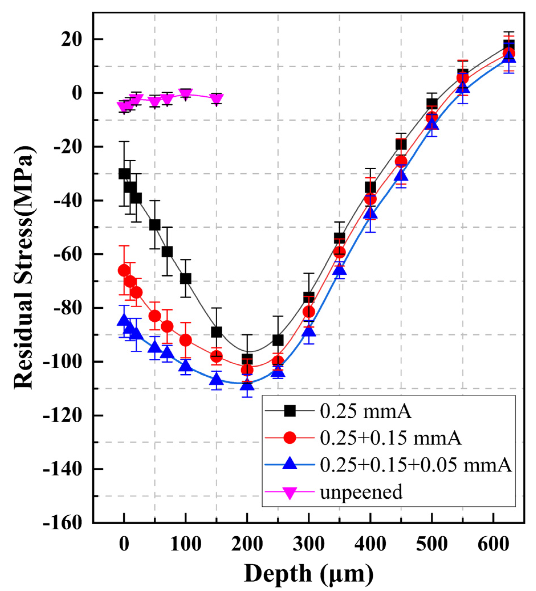
3.2. Residual Stresses Distribution after Multiple Shot Peening

Compressive residual stress fields could be generated in the plastic deformation layer of the samples treated by shot peening, which has a strengthening effect on many properties of the material, such as fatigue life, stress corrosion, etc. As shown in Figure 3, the three residual stress curves start to drop gradually in the near−surface layer region and then reach their extreme value at ~200 μm. With the continued increase in layer depth, the absolute values of residual compressive stresses rapidly decrease and finally reach 0 at ~600 μm. Secondary and triple peening process can significantly increase the residual stress of the sample surface from −30 to −66, −85 MPa. As the layer depth increases, the enhancement effect of multiple shot peening on the stress field gradually decreases and becomes relatively weak after 350 μm. Moreover, the maximum compressive residual stress in the subsurface were improved from −98 to −103 and −109 MPa as the peening passes increase.
When a large number of shots impact the material surface during shot peening, the kinetic energy of the particles is converted into plastic deformation energy of the shot peened layers as well as a residual stress field generated. With an increase in shot peening passes with the reduced diameter and intensity of the re−peening process, the overall strength of the residual stress field improves in parallel with a positive deepening of the near−surface residual stress fields, especially the surface layer of the samples. Simultaneously, owing to work hardening effect, after the first peening the resistance to plastic deformation of CNTs/Al−Mg−Si alloy composite was increased, which also makes a shallower depth of plastic deformation layer for the re−peening process. As the surface layer of the material is usually in direct contact with other components or the environment during service, the increase of residual compressive stress in the surface layer can effectively enhance the performance of the material such as wear resistance [26], stress corrosion [27] and fatigue life [28]. Furthermore, as seen in Figure 3, the uniformity of the residual stress field is also significantly improved after multiple peening, which would also lead to an increase in the stability of the CNTs/Al−Mg−Si alloy composite.

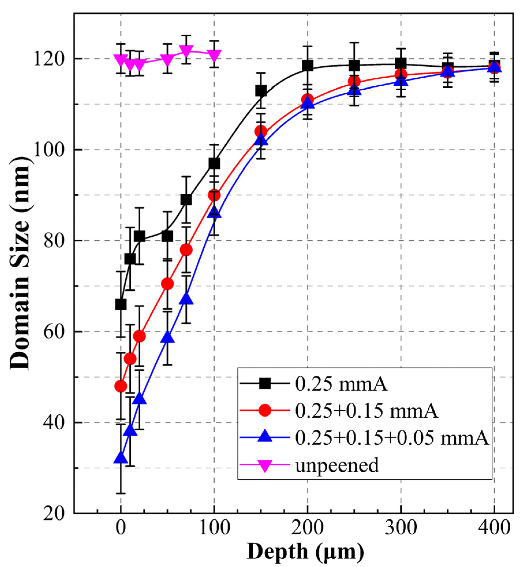
3.3. Domain Size and Microstrain after Multiple Shot Peening

A representative X-ray diffraction (XRD) pattern of the composite CNT/Al−Mg−Si alloy can be seen in Figure 4 showing the diffraction peaks of Al, CuAl2O4, and MgSiO3. Rietveld refinements were performed on X−patterns of the samples along the peened layer depths via Maud software to calculate the evolution of microstructure after peening treatment.
As can be seen in Figure 5, after the peening treatment, the average domain sizes were refined significantly in the surface layer and ramp up until it is equal to the substrate. As the peening process increased, the domain sizes of the near−surface layers were further refined, particularly for the surface, was decreased from 66 to 48 (secondary) and 32 nm (triple), respectively. With the increasing layer depth, the domain sizes minimized by multiple shot peening was gradually close to that by the primary shot peening, which had tended to be the same after 200 μm. The refinement of grain sizes is mainly caused by the plastic deformation due to the impact of the high−speed ceramic shots. Specially, as the surface layer is directly impacted by the shots, its plastic deformation is the highest in depths which leads to the maximum refinement of grains. With the increment of depth, the plastic deformation of the samples gradually decreases and the domain size becomes larger. In the secondary and triple peening processes, plastic hardening rate of the near surface layers increased, besides the kinetic energy and diameter of the shots was reduced, these lead to a shallow depth of plastic deformation layer caused by the multiple peening processes, as the refinement of grain size is mainly within 200 μm in depth.
When plastic deformation occurs in the peening layer, the microstrain in grains grows substantially. As shown in Figure 6, the microstrain in shot peened layers reached its maximum at the surface and declined dramatically with depth. In layers deeper than 350 μm, the magnitude of microstrain was close to the untreated specimens. With the increment of peening passes, the microstrain close to the surface was enlarged. Moreover, the microstrain of the surface layer of the material increased from 7.01 × 10⁻³ to 8.44 × 10⁻³ and 9.23 × 10⁻³, respectively, and when the layer depth exceeded 200 μm, the microstrain did not differ much from that of the primary shot peened layer.

3.4. Dislocation Density Variations after Multiple Shot Peening

A severe deformation during the shot peening process also produced many dislocations in grain. The growth and plugging of dislocations are the main causes of process hardening. For a statistical average, the dislocation density obtained by Rietveld refinement based on XRD patterns is shown in Figure 7. The values of the surface layer are 1.3 × 10¹⁴, 2.1 × 10¹⁴, 3.5 × 10¹⁴, respectively, and they fall rapidly with the increment of depth until approaching the density of substrate layers about ~0.3 × 10¹⁴.
As a face−centered cubic metal with high level of dislocation energy, the severe plastic deformation of the material when being impacted by the shot is mainly caused by the dislocation generation and mutual motion inside the dependent grains [29]. As the material surface is exposed to the impact of the projectile, its plastic deformation with refined grain size, increased microstrain is the largest and hence exhibits the highest dislocation density. For the secondary and triple peening passes, smaller shots diameter, and decreased peening intensity effectively reduces the impact kinetic energy of the shots to avoid uneven plastic deformation of the material surface, also makes the effect depth of the multiple peening mainly in the near surface of the material mainly limited to ~200 μm. Thus, the dislocation-reinforced layers of the samples were comparable.

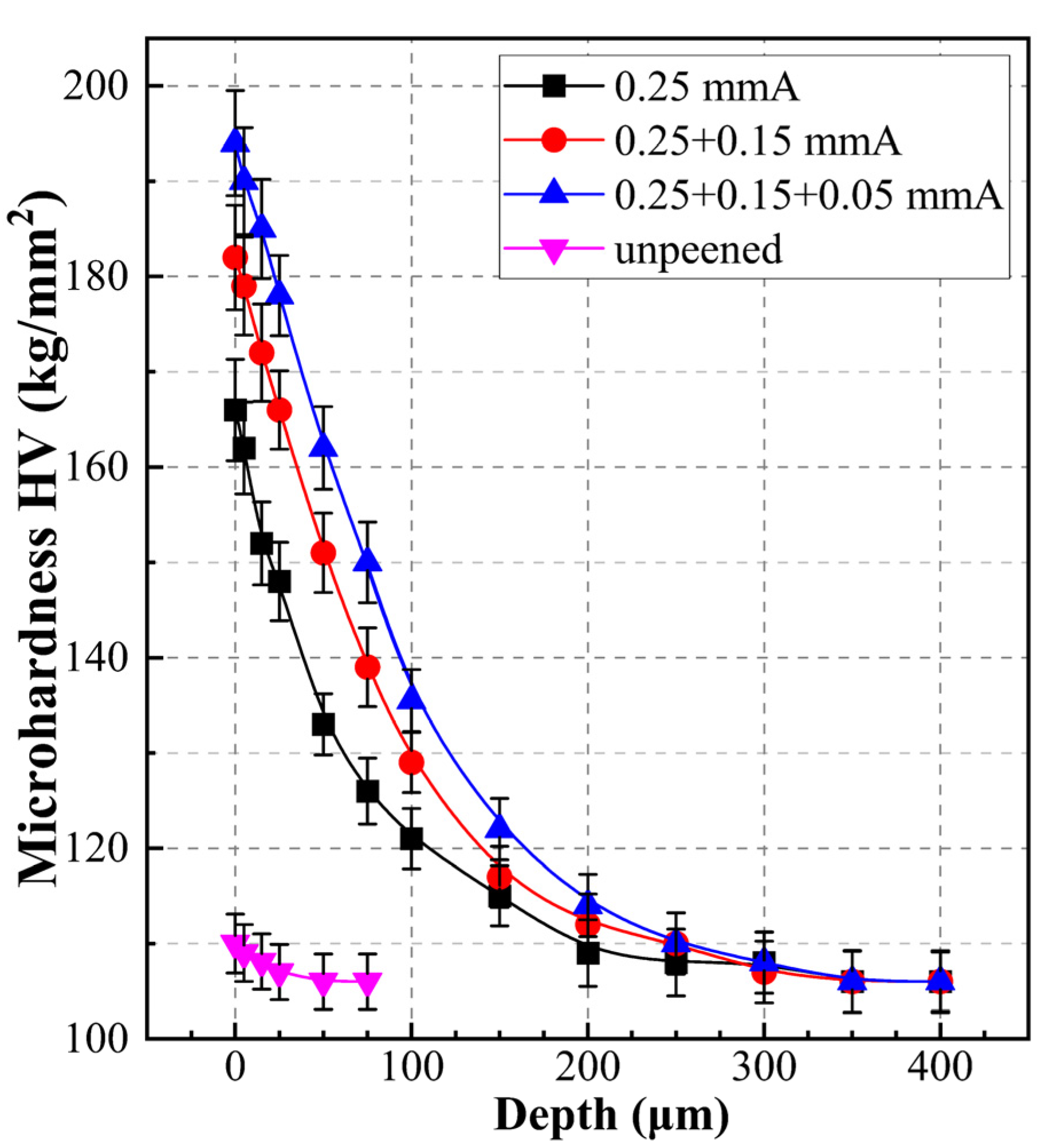
3.5. Microhardness Variance of Multiple Peened Layers

Figure 8 presents the microhardness−depth distribution in the multiple shot peening layers. As shown in Figure 8, the effect of dual and triple peening passes is significant in the near surface layer (~100 μm), and the microhardness of uppermost layer was increased from 165 to 182 (0.25 + 0.15 mmA) and 194 HV (0.25 + 0.15 + 0.05 mmA), respectively. Moreover, it is obvious from the evolution of standard deviations that improved uniformity of microhardness is exhibited with the additional peening process. This is attributed to the decreased peening intensity and the work hardening effect after the first peening process, by which the shots impact samples produce a smaller crater size, resulting in a more uniform stacking between craters, and generate more uniform plastic deformation in the work−hardened layers.

4. Conclusions

Multiple shot peening was performed on a CNTs/Al−Mg−Si alloy composite. The surface roughness of the peening treated layers was modified to 25.8 μm after the peening treatment (0.25 + 0.15 + 0.05 mmA). The transition between craters being smoother allows the material to prevent the formation of micro−cracks during elastic−plastic deformation [6]. Residual compressive stress fields near the surface layers were also effectively increased with integrated improvement after the secondary peening process, and could also suppress the formation of cracks on the surface. Furthermore, the grain size of the near−surface layer was refined, and the micro−strain and dislocation density were increased, which improve the work−hardening rate of the modified layer. In addition, multiple shot peening could also enhance the microhardness of the peened layers with a much finer distribution, and make the material properties more stable.

Author Contributions

Conceptualization, C.J. and K.Z.; methodology, Z.L., G.F., K.Z. and C.J.; software, K.Z., G.F.; validation, Z.L., G.F., K.Z. and C.J.; formal analysis, K.Z., Z.L., G.F. and C.J.; investigation, K.Z., Z.L., G.F. and C.J.; resources, K.Z., Z.L., G.F. and C.J.; data curation, K.Z. and G.F.; writing—original draft preparation, K.Z.; writing—review and editing, Z.L., G.F. and C.J.; visualization, Z.L., G.F. and C.J.; supervision, C.J.; project administration, C.J. and K.Z.; funding acquisition, K.Z., Z.L., G.F. and C.J. All authors have read and agreed to the published version of the manuscript.

Funding

This research was funded by Shanghai Sailing Program grant number [Nos. 22YF1410500], the National Key Research and Development Pro-gram of China grant number [Nos. 2017YFB1201105], the Natural Science Foundation of China grant number [Nos. 52171143].

Institutional Review Board Statement

Not applicable.

Informed Consent Statement

Not applicable.

Data Availability Statement

Not applicable.

Conflicts of Interest

The authors declare no conflict of interest.

References

  1. Bagherifard, S. Enhancing the Structural Performance of Lightweight Metals by Shot Peening. Adv. Eng. Mater. 2019, 21, 1801140. [Google Scholar] [CrossRef]
  2. Xu, R.; Tan, Z.; Fan, G.; Ji, G.; Xiong, D.-B.; Guo, Q.; Su, Y.; Li, Z.; Zhang, D. High−strength CNT/Al−Zn−Mg−Cu composites with improved ductility achieved by flake powder metallurgy via elemental alloying. Compos. Part A Appl. Sci. Manuf. 2018, 111, 1–11. [Google Scholar] [CrossRef]
  3. Shin, S.E.; Bae, D.H. Fatigue behavior of Al2024 alloy−matrix nanocomposites reinforced with multi−walled carbon nanotubes. Compos. Part B Eng. 2018, 134, 61–68. [Google Scholar] [CrossRef]
  4. Liu, Z.Y.; Zhao, K.; Xiao, B.L.; Wang, W.G.; Ma, Z.Y. Fabrication of CNT/Al composites with low damage to CNTs by a novel solution−assisted wet mixing combined with powder metallurgy processing. Mater. Des. 2016, 97, 424–430. [Google Scholar] [CrossRef]
  5. Najimi, A.A.; Shahverdi, H.R. Microstructure and mechanical characterization of Al6061−CNT nanocomposites fabricated by spark plasma sintering. Mater. Charact. 2017, 133, 44–53. [Google Scholar] [CrossRef]
  6. Bi, S.; Liu, Z.Y.; Yu, B.H.; Ma, G.N.; Wu, L.H.; Xiao, B.L.; Ma, Z.Y. Superplastic deformation behavior of carbon nanotube reinforced 7055 Al alloy composites. Mater. Sci. Eng. A 2020, 797, 140263. [Google Scholar] [CrossRef]
  7. Meng, X.; Liu, T.; Shi, C.; Liu, E.; He, C.; Zhao, N. Synergistic effect of CNTs reinforcement and precipitation hardening in in−situ CNTs/Al–Cu composites. Mater. Sci. Eng. A 2015, 633, 103–111. [Google Scholar] [CrossRef]
  8. Wang, C.; Wang, C.; Wang, L.; Lai, Y.; Li, K.; Zhou, Y. A dislocation density–based comparative study of grain refinement, residual stresses, and surface roughness induced by shot peening and surface mechanical attrition treatment. Int. J. Adv. Manuf. Technol. 2020, 108, 505–525. [Google Scholar] [CrossRef]
  9. Zhang, Z.W.; Liu, Z.Y.; Xiao, B.L.; Ni, D.R.; Ma, Z.Y. High efficiency dispersal and strengthening of graphene reinforced aluminum alloy composites fabricated by powder metallurgy combined with friction stir processing. Carbon 2018, 135, 215–223. [Google Scholar] [CrossRef]
  10. Kwon, H.; Estili, M.; Takagi, K.; Miyazaki, T.; Kawasaki, A. Combination of hot extrusion and spark plasma sintering for producing carbon nanotube reinforced aluminum matrix composites. Carbon 2009, 47, 570–577. [Google Scholar] [CrossRef]
  11. Mondal, S. Aluminum or Its Alloy Matrix Hybrid Nanocomposites. Met. Mater. Int. 2020, 27, 2188–2204. [Google Scholar]
  12. Trinh, P.V.; Luan, N.V.; Phuong, D.D.; Minh, P.N.; Weibel, A.; Mesguich, D.; Laurent, C. Microstructure, microhardness and thermal expansion of CNT/Al composites prepared by flake powder metallurgy. Compos. Part A Appl. Sci. Manuf. 2018, 105, 126–137. [Google Scholar] [CrossRef]
  13. Liu, Z.Y.; Xiao, B.L.; Wang, W.G.; Ma, Z.Y. Modelling of carbon nanotube dispersion and strengthening mechanisms in Al matrix composites prepared by high energy ball milling−powder metallurgy method. Compos. Part A Appl. Sci. Manuf. 2017, 94, 189–198. [Google Scholar] [CrossRef]
  14. Chen, M.; Fan, G.; Tan, Z.; Yuan, C.; Guo, Q.; Xiong, D.; Chen, M.; Zheng, Q.; Li, Z.; Zhang, D. Heat treatment behavior and strengthening mechanisms of CNT/6061Al composites fabricated by flake powder metallurgy. Mater. Charact. 2019, 153, 261–270. [Google Scholar] [CrossRef]
  15. Chen, M.; Fan, G.; Tan, Z.; Xiong, D.; Guo, Q.; Su, Y.; Zhang, J.; Li, Z.; Naito, M.; Zhang, D. Design of an efficient flake powder metallurgy route to fabricate CNT/6061Al composites. Mater. Des. 2018, 142, 288–296. [Google Scholar] [CrossRef]
  16. Cao, P.; So, K.P.; Yang, Y.; Park, J.G.; Li, M.; Yan, L.; Hu, J.; Kirk, M.; Li, M.; Lee, Y.H.; et al. Carbon nanotube (CNT) metal composites exhibit greatly reduced radiation damage. Acta Mater. 2021, 203, 116483. [Google Scholar] [CrossRef]
  17. So, K.P.; Kushima, A.; Park, J.G.; Liu, X.; Keum, D.H.; Jeong, H.Y.; Yao, F.; Joo, S.H.; Kim, H.S.; Kim, H.; et al. Intragranular Dispersion of Carbon Nanotubes Comprehensively Improves Aluminum Alloys. Adv. Sci. 2018, 5, 1800115. [Google Scholar] [CrossRef]
  18. Cao, L.; Chen, B.; Wan, J.; Kondoh, K.; Guo, B.; Shen, J.; Li, J.S. Superior high−temperature tensile properties of aluminum matrix composites reinforced with carbon nanotubes. Carbon 2022, 191, 403–414. [Google Scholar] [CrossRef]
  19. Chen, B.; Shen, J.; Ye, X.; Imai, H.; Umeda, J.; Takahashi, M.; Kondoh, K. Solid−state interfacial reaction and load transfer efficiency in carbon nanotubes (CNTs)−reinforced aluminum matrix composites. Carbon 2017, 114, 198–208. [Google Scholar] [CrossRef]
  20. Khanna, V.; Kumar, V.; Bansal, S.A. Mechanical properties of aluminium−graphene/carbon nanotubes (CNTs) metal matrix composites: Advancement, opportunities and perspective. Mater. Res. Bull. 2021, 138, 111224. [Google Scholar] [CrossRef]
  21. Shin, S.E.; Ko, Y.J.; Bae, D.H. Mechanical and thermal properties of nanocarbon−reinforced aluminum matrix composites at elevated temperatures. Compos. Part B Eng. 2016, 106, 66–73. [Google Scholar] [CrossRef]
  22. Mokdad, F.; Chen, D.L.; Liu, Z.Y.; Ni, D.R.; Xiao, B.L.; Ma, Z.Y. Hot deformation and activation energy of a CNT−reinforced aluminum matrix nanocomposite. Mater. Sci. Eng. A 2017, 695, 322–331. [Google Scholar] [CrossRef]
  23. Sahu, P.; Pradhan, S.K.; De, A. X-ray diffraction studies of the decomposition and microstructural characterization of cold−worked powders of Cu−15Ni−Sn alloys by Rietveld analysis. J. Alloy. Compd. 2004, 377, 103–116. [Google Scholar] [CrossRef]
  24. Chandan, A.K.; Hung, P.T.; Kishore, K.; Kawasaki, M.; Chakraborty, J.; Gubicza, J. On prominent TRIP effect and non−basal slip in a TWIP high entropy alloy during high−pressure torsion processing. Mater. Charact. 2021, 178, 111284. [Google Scholar] [CrossRef]
  25. Boukeffa, S.; Tebib, W.; Laidi, R.; Redouani, L.; Bououdina, M. Parametrics XRD Rietveld refinements of mechanically activated solid−state reactions in iron−brass alloy. Mater. Today Commun. 2022, 32, 104150. [Google Scholar] [CrossRef]
  26. Wang, Y.; Li, C.; Yang, H.; Wang, X.; Deng, J.; Yu, X. The growth of anti−friction and wear−resistance TiO2 nanotube arrays driven by residual stress. Tribol. Int. 2021, 154, 106736. [Google Scholar] [CrossRef]
  27. Rajaguru, J.; Arunachalam, N. A comprehensive investigation on the effect of flood and MQL coolant on the machinability and stress corrosion cracking of super duplex stainless steel. J. Mater. Process. Technol. 2020, 276, 116417. [Google Scholar]
  28. Hultgren, G.; Mansour, R.; Barsoum, Z.; Olsson, M. Fatigue probability model for AWJ−cut steel including surface roughness and residual stress. J. Constr. Steel Res. 2021, 179, 106537. [Google Scholar] [CrossRef]
  29. George, R.; Kashyap, K.T.; Rahul, R.; Yamdagni, S. Strengthening in carbon nanotube/aluminium (CNT/Al) composites. Scr. Mater. 2005, 53, 1159–1163. [Google Scholar] [CrossRef]
Figure 1. (a,b) show microstructure of CNTs/Al−Mg−Si alloy composite before shot peening.
Metals 12 01412 g001
Figure 2. Surface topography of the specimen untreated by peening process (a), and after (b) 0.25 mmA (c) 0.25 + 0.15 mmA, (d) 0.25 + 0.15 + 0.05 mmA peening treatment.
Metals 12 01412 g002
Figure 3. Residual stress of CNT/Al−Mg−Si alloy composite treated by multiple shot peening.
Metals 12 01412 g003
Figure 4. A typical X-ray pattern of CNTs/Al−Mg−Si alloy composite.
Metals 12 01412 g004
Figure 5. Domain size−depth distribution of CNTs/Al−Mg−Si alloy composite after multiple shot peening.
Metals 12 01412 g005
Figure 6. Distribution of microstrain of CNTs/Al−Mg−Si alloy composite after multiple shot peening.
Metals 12 01412 g006
Figure 7. Dislocation density−depth distribution after multiple shot peening.
Metals 12 01412 g007
Figure 8. Microhardness−depth distribution of CNTs/Al−Mg−Si alloy composite treated by multiple shot peening.
Metals 12 01412 g008
Table 1. Parameters of multiple shot peening.
SamplesShots MaterialShot Diameter (mm)Peening Intensity (mmA)Peening Time (s)
1ceramic0.250.2530
2ceramic0.25, 0.1250.25, 0.1530 + 30
3ceramic0.25, 0.1250.25, 0.15, 0.0530 + 30 + 30
Publisher’s Note: MDPI stays neutral with regard to jurisdictional claims in published maps and institutional affiliations.

