Article

Activation Behavior of {10-12}-{10-12} Secondary Twins by Different Strain Variables and Different Loading Directions during Fatigue Deformation of AZ31 Magnesium Alloy

1
School of Materials Science and Engineering, Chongqing University of Technology, Chongqin 400000, China
2
School of Material Science and Engineering, Southwest Jiaotong University, Chengdu 611756, China
*
Author to whom correspondence should be addressed.
Metals 2022, 12(9), 1433; https://doi.org/10.3390/met12091433
Submission received: 2 July 2022 / Revised: 22 August 2022 / Accepted: 22 August 2022 / Published: 29 August 2022

Abstract

:
The tensile and compression fatigue deformation tests of AZ31 magnesium alloy were carried out at room temperature, and the activation behavior of {10-12}-{10-12} secondary twins in different loading directions (ND normal direction, RD rolling direction) and different strain amplitude (0.5%, 1%) was studied. The results showed that {10-12}-{10-12} secondary twins were observed on the fracture surface of the fatigue samples in the ND at the strain of 1%. In contrast, no secondary twins were observed in the ND at the strain of 0.5% nor in the RD at the strain of 1% and 0.5%, and the fatigue life in the ND was greater than that in the RD. The analysis showed that the generation of {10-12}-{10-12} secondary twins was associated with the grain size and loading direction and that the fatigue deformation at 1% strain was more likely to generate {10-12}-{10-12} secondary twins due to the large lamellar thickness of the primary twins generated at relatively large strain conditions. The fatigue deformation along the ND tension was more favorable for the activation of multiple {10-12} primary twins, and the interaction of multiple twin variants was more favorable to activate {10-12}-{10-12} secondary twins.

1. Introduction

Magnesium alloy is a light metal structural material with a high specific strength and stiffness, good vibration damping, high thermal conductivity, and excellent machinability. It has good applications for engineering structural parts in automotive, electronic communication, aerospace, weaponry, and other fields [1,2,3,4]. However, since the independent slip system in magnesium alloys is not sufficient to provide a full amount of plastic deformation, twinning is used as an alternative intracrystalline plastic deformation mode [5,6,7]. It was found that several twinning systems exist in magnesium alloys, the most common of which are {10-12} tensile twins and {10-11} compressive twins. When a tensile stress load is applied along the c-axis direction or a compressive stress load is applied perpendicular to the c-axis, it tends to activate tensile twinning along {10-12} with a grain rotation of approximately 86.3°; on the contrary, when a compressive stress load is applied along the c-axis direction or a tensile stress load is applied perpendicular to the c-axis, it produces compressive twinning along {10-11} with a grain rotation of approximately 56.2° [8,9,10]. The onset of the twinning mode varies with the loading method or loading direction, and the type of twinning produced varies.
In a previous study, we found a large number of {10-12}-{10-12} secondary twin layers in high circumferential fatigue samples after characterization of fatigue fractures of an AZ31 magnesium alloy, which are widely present inside the primary {10-12} twins [11]. This provides a strong basis for studying the fatigue failure of magnesium alloys. In a study by Yu et al. [12] on the fatigue behavior of single-crystal magnesium, it was pointed out that in the fully reversed strain-controlled fatigue test, a significant twinning–detwinning phenomenon occurred on the sample surface, and the residual twins formed a large number of twin layers, leading to cracking along the twin boundary. Fatigue microcracking started at the {10-12} twin boundary, and the final fatigue fracture was most likely directly related to the {10-11}-{10-12} secondary twinning. These findings suggest that secondary twinning should be taken into account as a deformation mechanism. In addition, some studies further suggest that the formation of secondary twins is related to the grain size, loading direction, and strain amplitude [13,14]. Lentz et al. [13] performed cyclic deformation on magnesium single crystals and found that secondary twins and tertiary twins were activated under high strain deformation, but the activation of secondary twins was strongly correlated with the size of primary twins. Xin et al. [14] pointed out that the thickness of {10-12} twin lamella plays a similar role as that of grain size. Due to the small size of {10-12} twins, the activation stress for {10-12}-{10-12} should be much higher. The authors indicated that tensile strain along the ND is easier to activate {10-12}-{10-12} secondary twins. A number of publications have indicated that the fatigue deformation mechanism of magnesium alloys was directly related to the strain amplitude. An earlier work by Li et al. [15] suggested that when the strain amplitude was higher than 0.5%, twinning was the dominant mechanism, and when the strain amplitude is less than 0.5%, dislocation slip is the dominant mechanism. Matsuzuki et al. [16] also reported that in the process of fatigue deformation with high stress amplitude, the de-twinning behavior was dominant, while in the process of fatigue deformation with low stress amplitude, dislocation slip was dominant. However, there has been little work on the correlation between the activation of {10-12}-{10-12} secondary twins and grain size, loading direction, and stress amplitude during fatigue deformation.
Therefore, in this paper, an AZ31 magnesium alloy was selected to investigate the {10-12}-{10-12} secondary twinning activation behavior of an AZ31 magnesium alloy under different loading directions (ND, RD) and different strain amplitudes (0.5%, 1%), using a room temperature tensile-compression fatigue test.

2. Experimental Procedure

The fatigue specimens were cut in RD and ND directions by wire cutting on a commercial hot-rolled AZ31 (3 wt% Al–1 wt% Zn) magnesium alloy plate. The as-received material used in this experiment was consistent with those used in our previous paper [17]. The microstructure of the original material presented a twin-free feature, and the average grain size was approximately 35 µm. All samples were of the same size along RD and ND directions, with the width of 10 mm, thickness of 4 mm, and length of 70 mm. The shape and dimensions are shown in Figure 1. The surface of the specimens was then polished with metallographic sandpaper (SiC) and tin-free sandpaper to make the surface smooth and free of obvious scratches. The fatigue test was carried out on the MTS809 fatigue test machine (Metes Industrial Systems, Inc, Eden Prairie, MN, USA) in tensile-compression full inverse fatigue test (R = −1) with strain control mode, and the frequency of the fatigue test was 0.5 Hz. The fatigue test was carried out at two strain amplitudes of 0.5% and 1%, respectively, and at least three specimens were tested in each condition.
A small piece, 8 mm in length, 4.5 mm in width, and 4 mm in height, was cut near the fracture of the fatigued sample, and the surface of the sample was polished with tin-free sandpaper until there were no obvious scratches on the surface to avoid external factors affecting the test results. The samples were electrolytically polished with AC2 (AC2 solution: 800 mL ethanol, 100 mL isopropanol, 18.5 mL distilled water, 41.5 g sodium hydrosulfide, 75 g 8-hydroxyquinoline, 75 g citric acid, 15 mL perchloric acid), polishing solution at a polishing temperature of −28 °C, voltage of 20 V, current control of 0.03–0.06 A, and a polishing time of 2 min 50 s. The fatigue fracture morphology was observed by scanning electron microscopy (SEM, FEI Nova 400, Thermo Fisher Scientific Brno s.r.o., Thermo Fisher Scientific Inc., 168 Third Avenue Waltham, MA, USA). To identify the twin type, the sample surface was characterized by electron backscatter diffraction (EBSD) technique with a scan step of 0.5 μm. The obtained EBSD data were processed using the HKLChannel 5 software (SEM, FEI Nova 400, Oxford Instruments Technology (Shanghai Co., Ltd., Shanghai, China) package.

3. Results and Discussion

3.1. Fatigue Behavior

The hysteresis curves corresponding to cyclic tensile compression loading with different stresses and different loading directions are shown in Figure 2. The hysteresis loops under different strain variables and different loading directions are characterized by the obvious asymmetry of the hysteresis loops, and the phenomenon occurs due to the different deformation mechanisms during tensile and compressive deformation during fatigue loading, with alternating twinning and de-twinning behaviors [18,19]. Figure 2a,c shows the stress–strain hysteresis loops of the initial first cycle, second cycle, and half-life cycle of fatigue under the ND and RD directions, respectively. These loops can be decomposed into four deformation processes: tensile loading, tensile unloading, compression loading, and compression unloading. When deformation occurs along the RD direction, the stress increases with the increase in strain. At the beginning of the tensile loading phase, the loop starts with a straight-line segment with a large slope, indicating that elastic deformation occurs in the specimen at this time [20,21]. The curve then shows a small convex upward curve, indicating that the deformation mechanism of the specimen during the tensile loading stage is mainly slip [22,23]. In the tensile unloading process, the specimen continues to deform elastically until the inflection point, when the stress has reached the compression stage. In compression, the half-turn curve reaches a plateau which should be caused by twin deformation [24]. That is, the compressive load applied along the RD (stresses perpendicular to the c-axis of the grain) mainly produces easily activated twins inside the grain. In addition, the peak tensile stress is significantly higher than the peak compressive stress.
When cyclic loading is performed along the ND direction, the deformation mechanism during the first stretching process mainly occurs as twinning behavior because the c-axis of most of the grains in the initial grains is parallel to the loading direction. The stress increases slowly with the strain to reach the plateau, and the curve behaves as a relatively flat curve. The pressure–strain curve is relatively stable in this range. When the load changes to a compressive load, although the substrate is subjected to compressive load in the direction parallel to the c-axis, the twinning occurs in the twinning region due to the twinning of most of the grains during the first stretching, which results in the twinning being subjected to compressive load perpendicular to the c-axis and easily activates the re-twinning. After the complete detwinning behavior in the twinning region has occurred, the deformation mode is dominated by slip [18]. In addition, the peak tensile stress is significantly lower than the peak compressive stress. Therefore, the shape of the hysteresis curve is reversed when cyclically loaded in the ND direction in tension-compression compared to when it is cyclically loaded in the RD direction [25,26]. Considering the microstructural changes, the {0001} base of most grains of the rolled magnesium alloy is parallel to the rolling surface, leading to a different order of twinning and dislocation excitation with fatigue deformation along different directions: along the rolling direction fatigue, the tensile phase is dominated by dislocations and the compression phase is dominated by twinning, while along the normal direction fatigue, the tensile phase is thought to be dominated by twinning and the compression phase is dominated by dislocations [24]. ND specimens with significantly lower tensile peaks showed compressive mean stresses, while RD specimens showed tensile mean stresses. It is known that the tensile mean stress accelerates the crack extension and fatigue damage accumulation, which adversely affects the cyclic fatigue life of the material, while the opposite is true for the compressive mean stress [24]. Therefore, the ND specimens have better fatigue resistance than the RD specimens for the same strain amplitude.
Since the rolled magnesium alloys have a strong basal texture [27] and the twinning behavior occurs directionally, {10-12} twinning is suppressed when compressed along the c-axis of the grain or pulled along the a-axis [28]. It is known that when compressed along the ND direction, the c-axis of these twins is almost perpendicular to the reloading direction. At the early stage of further deformation, the activation of the receding twin is more difficult in ND specimens than in RD specimens. In the RD specimen, a single {10-12} twin variant or a pair of {10-12} twins appear. In contrast, multiple {10-12} twin variants are usually activated simultaneously in one grain in the latter case. During subsequent compression along the normal direction, the detwinning process is effectively retarded for the samples containing multiple {10-12} twin variants in one grain. Meanwhile, the yield stress of corresponding samples is enhanced, compared to that of the samples containing a single {10-12} twin variant or a {10-12} twin pair in one grain [29]. As a result, the average lifetime in the ND direction is greater than that in the RD direction.

3.2. Surface Microstructure Characteristics of the Sample

To identify the type of twin activated in the AZ31 magnesium alloy during tensile-compression cyclic loading, the EBSD technique was used to characterize the fracture surface of fatigue specimens. Table 1 lists the common twinning types in magnesium alloys, the orientation difference angle between the twin and the matrix, and the corresponding axis of rotation.
Figure 3 shows the EBSD maps of the fracture surfaces of the four fatigue specimens, (a) and (b) for the ND direction (1%, 0.5%) and (c) and (d) for the RD direction (1%, 0.5%). It is observed that a large number of laminas appear in Figure 3a, and there is the appearance of irregular secondary twin layers in the primary laminas. When tension occurs along the ND, it can be clearly seen that most of the grains have a large number of twins activated inside the grains. The shape of the twins in the ND direction is disordered, the twins have different orientations and are cross-distributed in the grains, and the interaction between the different twin variants generates stress concentration, which excites secondary twinning. Therefore, the twinning organization contains not only the common primary twins, but also many secondary twins.
The twinning morphology inside the grain when following the RD direction is simpler compared to the twinning morphology generated along the ND direction. It can be seen in Figure 3c that there are more twin layers distributed inside the matrix, while the internal twins of the grains are parallel to each other and have only one direction. During the first compressive deformation, most of the grains are subjected to compressive stress along the c-axis, which tends to activate {10-12} twins. Since most of the twins are almost parallel or perpendicular to each other, there is no crossover, so the secondary twins are not excited. Therefore, no secondary twins are observed in the RD. According to the experimental results, it can be concluded that the formation of secondary twins is related to the loading direction of AZ31, and {10-12}-{10-12} secondary twins can be activated in the ND. It can be also found in the deformation study of magnesium alloys by Xin et al. [30], multiple {10-12} twin variants were produced in the magnesium alloy samples tensioned along the ND, and {10-12}-{10-12} secondary twins were activated at the twin–twin interactions accordingly. In contrast, only a single {10-12} twin variant or a pair of {10-12} twin variants appeared in the RD samples [29], which could not activate secondary twins. Volume fractions of the {10-12} primary twins and {10-12}–{10-12} secondary twins in Figure 3 are measured and listed in Table 2. The twin volume fractions were measured by the area fraction of twin regions in the inverse pole figure maps. {10-12}–{10-12} secondary twins can be observed in the sample fatigued along ND during the strain amplitude of 1%, and the volume fraction was 21.1%. No {10-12}–{10-12} twins can be observed in the other samples.
Figure 4a is a magnification image from the white rectangular zone in Figure 3a, where part of the red {10-12} twin boundary in this region is located inside the primary {10-12} twin from the ND direction at 1% strain. This is because the secondary {10-12} twin was activated inside the primary {10-12} twin, and the primary {10-12} twin was cut off by the {10-12}-{10-12} secondary twin. The interface of the primary twin does not only have the features of the {10-12} primary twin, but it also contains some features of the {10-12}-{10-12} secondary twin. The distribution peaks around 86° in Figure 4b are associated with the {10-12} tension twins, and those around 60° are associated with the {10-12}-{10-12} secondary twins. Therefore, we can conclude that these twin laminas are {10-12}-{10-12} secondary twins. In contrast, in the sample with the strain of 0.5%, as shown in Figure 3b, it can be observed that only a small amount of primary twin laminas were produced under this condition, and no secondary twin laminas appear. These secondary twin morphologies produced when tensioned along the ND are relatively small, indicating that the growth of secondary twins is limited by the primary twins.
According to Lentz et al. [31], the grain size not only has an effect on the primary twinning behavior, but it also has a more significant effect on the secondary and tertiary twinning, where secondary twinning is particularly sensitive to the grain size because secondary twinning is mostly transformed from primary twinning, or exists inside primary twinning, and secondary twinning decreases sharply when the grain size decreases. The {10-12}-{10-12} secondary twinning is closely related to the thickness size of the primary twin {10-12}, and the activation of the {10-12} primary twin is related to the grain size [32]. During the multidirectional loading of AZ31 magnesium alloy by Xin et al. [14], it was found that {10-12}-{10-12} secondary twins existed in the samples, and the activation of secondary twins was directly related to the size of primary {10-12} twins, when the initial {10-12} twin was large enough, the {10-12}-{10-12} secondary twin was bound to arise. When the sample was at 0.5% strain, the strain was small and the number of fatigue cycles was high, and the resulting primary twin layers are small. These twins are straight, thin, and long, and in addition, the {10-12}-{10-12} secondary twin interface is difficult to observe in this region. In fatigue samples with 1% strain, the thickness of the primary {10-12} twin is too large to alleviate the local strain incongruity, which can activate the {10-12}-{10-12} secondary twin formation at high strain amplitudes. The size of the {10-12} primary twin becomes thinner with increasing cycle numbers. The experimental results show that only a few {10-12}-{10-12} secondary twins are seen at lower strains (0.5%), while a large number of {10-12}-{10-12} secondary twins are observed when formed at higher strains (1%).

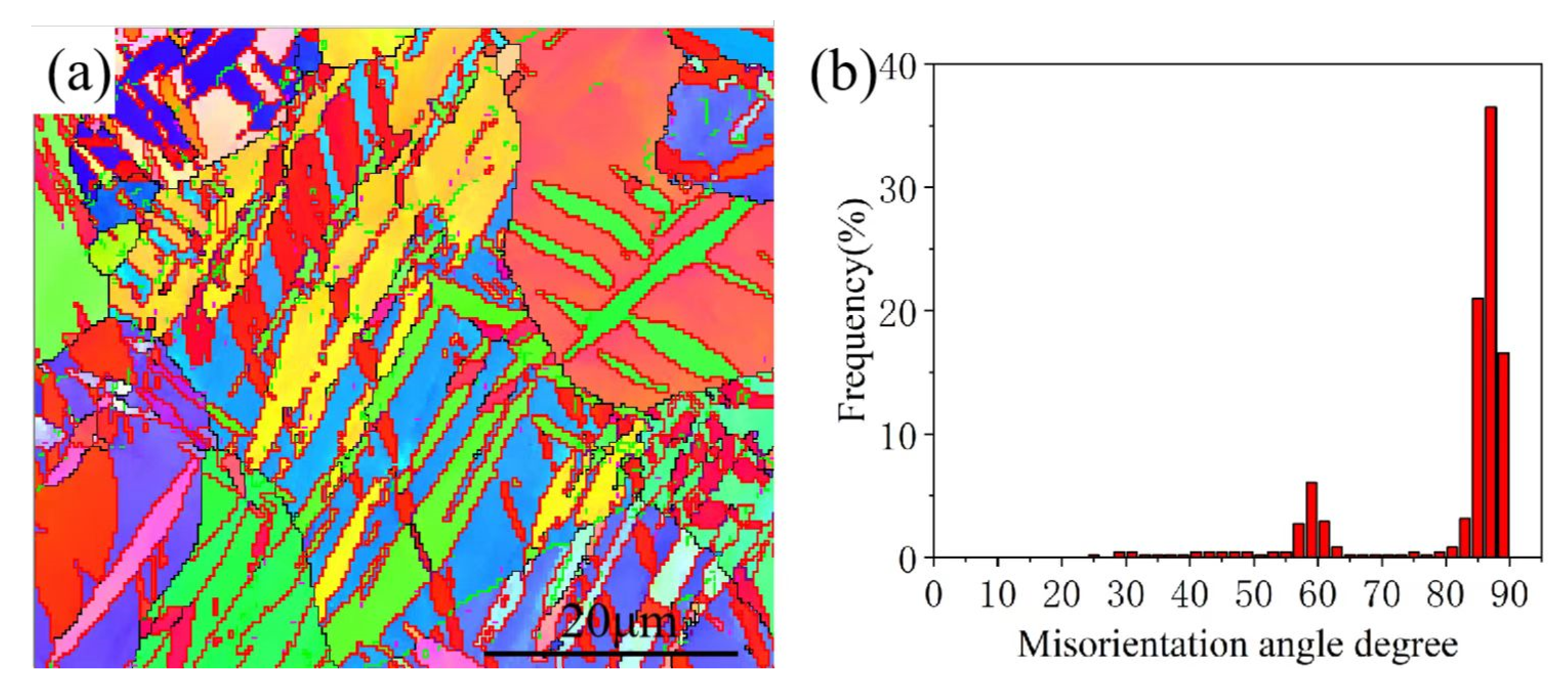
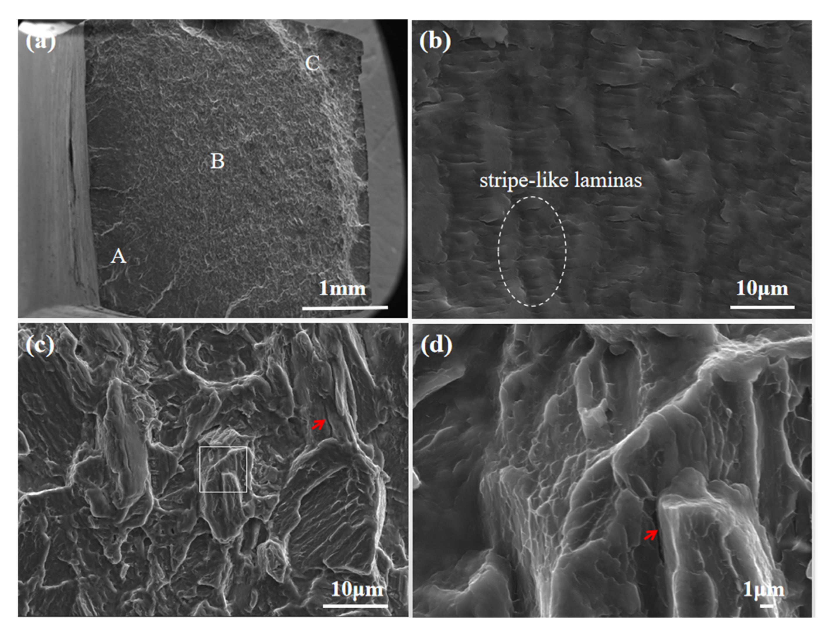
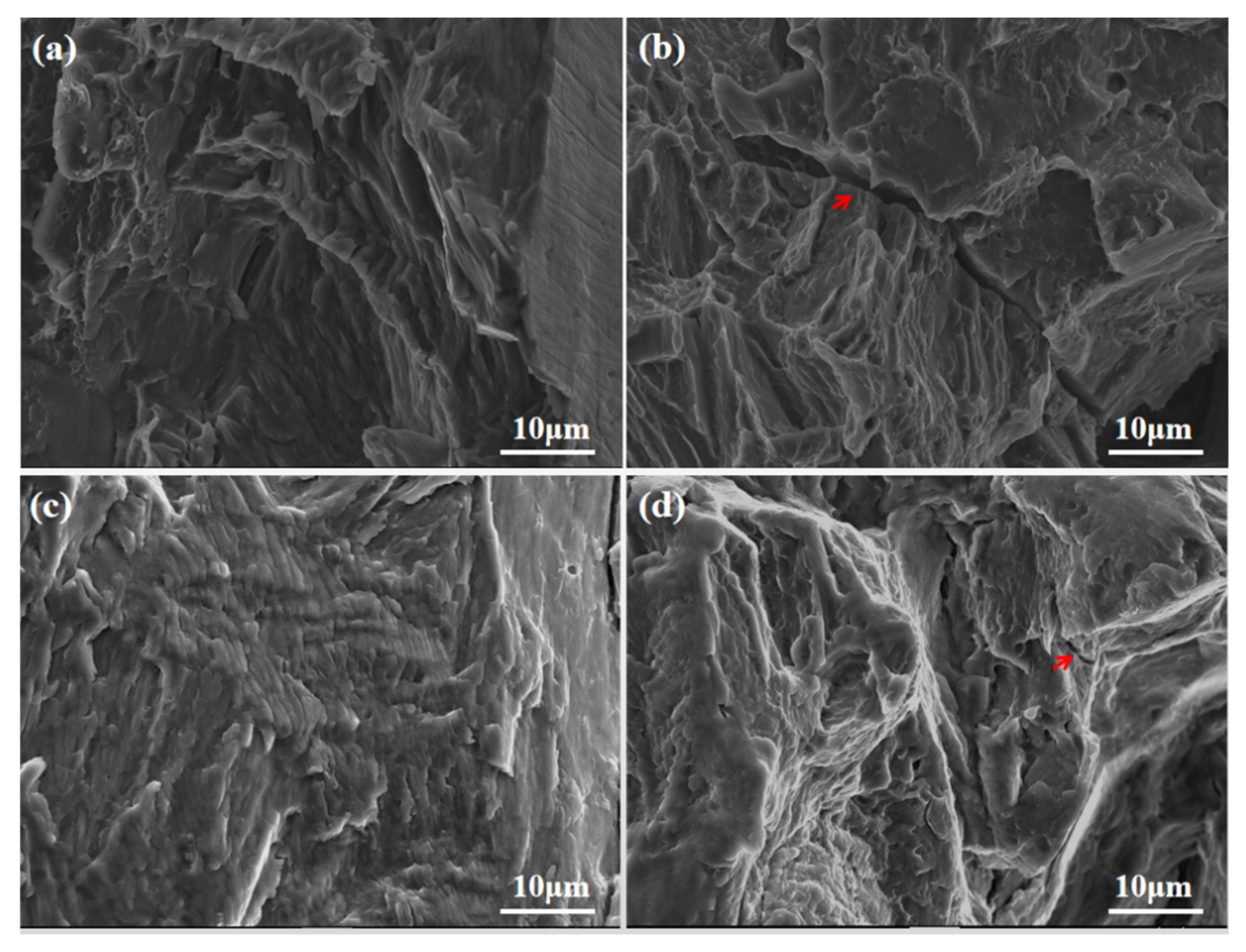
3.3. Microstructure Characteristics of the Fracture Surface

A typical fatigue fracture consists of three parts: fatigue initial zone, crack propagation zone, and final fracture zone, which correspond to the three regions, A, B, and C, in Figure 5a and Figure 6a, respectively. The initial fatigue zone is the fatigue fracture initiation point, and most of the fatigue crack sources are close to the sample’s surface. The crack propagation zone is formed by the repeated opening and closing of the crack tip after the crack formation. When the fatigue crack extends to the point where the applied load is greater than the maximum stress that the remaining area of the sample can withstand, the sample will fracture rapidly to form the fatigue final fracture zone. The crack propagation zone is rougher and darker than the fatigue source zone [33].
The fatigue fracture morphology of the specimens differs significantly due to the different fatigue loading directions and the deformation mechanisms. The fatigue fracture morphology near the fracture of the specimens with 1% strain in the ND is shown in Figure 5. In the high magnification image Figure 5b, a large number of lamellar structures are observed in the primary twin, as shown in the elliptical region in the figure, and these lamellar structures split the original primary twin into multiple stripe-type regions parallel to each other. Microcracks were also found in the crack propagation zone, as shown by the red arrows. In the previous study, it was found that a large number of {10-12}-{10-12} secondary twin layers existed in the fatigued samples of AZ31 magnesium alloy, and these laminas were widely present inside the primary {10-12} twins. This indicates that a large number of {10-12}-{10-12} secondary twins are activated in the magnesium alloy in the ND direction and at a high strain amplitude of 1%. Figure 6 shows the fatigue fracture morphology of the ND 0.5% specimen, where the number of lamellar structures observed in the primary twin is less than in the specimen with 1% strain. At 0.5% strain, the smaller strain and the large number of cycles result in too narrow thickness of the primary {10-12} twin and therefore cannot activate the {10-12}-{10-12} secondary twin at low strain amplitudes. As shown in Figure 7a,b, specimens with 0.5% strain and (c, d) specimens with 1% strain are the fatigue fracture morphology of the specimens at two different strains in the RD direction. The microcracks are shown by the red arrows in the figures. It can be seen from the figures that almost no lamellar structure is observed in the RD direction, which indicates that {10-12}-{10-12} secondary twins were not activated in this direction.

4. Conclusions

For the study of the activation of secondary twinning of AZ31 magnesium alloy {10-12}-{10-12} under different strain variables and different loading directions, the following points were obtained.
(1) The thickness of the primary {10-12} twin at 1% strain is large enough to activate the {10-12}-{10-12} secondary twin. In contrast, at 0.5% strain, the thickness of the primary {10-12} twin is too narrow to activate the {10-12}-{10-12} secondary twin at low strain amplitude. Therefore, {10-12}-{10-12} secondary twins were observed on the fracture surface of fatigue samples at a strain of 1%, and {10-12}-{10-12} secondary twins were not observed at a strain of 0.5%.
(2) The shape of the twins in the ND direction is disordered, and the interaction between different twin variants generates severe stress concentration phenomena, which activates secondary twinning. In contrast, the twinning of the grains along the RD direction is simpler, and most of the twins are almost parallel or perpendicular to each other; thus no secondary twinning is activated. As a result, {10-12}-{10-12} secondary twinning can be observed in the ND direction, while no secondary twinning is observed in the RD direction.
(3) The tension along ND activates multiple {10-12} twin variants, while the compression along RD produces a relatively single {10-12} variant and the twin–twin interfaces, where multiple {10-12} twin variants inhibit the occurrence of the detwinning behavior. Therefore, it leads to a larger number of cycles in the ND direction than in the RD direction.

Author Contributions

Data curation, X.H.; Formal analysis, Y.W.; Investigation, Q.S.; Methodology. Y.Z.; Project administration, J.T.; Supervision, Z.Z.; Wirting-review & editing, L.T. All authors have read and agreed to the published version of the manuscript.

Funding

This research was financially supported by the National Natural Science Foundation of China (51901030, 51801165); the Natural Science Foundation of Chongqing (cstc2017jcyjAX0381, cstc2020jcyj-msxmX0877, cstc2019jcyj-msxmX0183); the Science and Technology Research Program of the Chongqing Municipal Education Commission (KJQN201901118, KJQN202001101, KJQN201901117); and the Scientific Research Foundation of Chongqing University of Technology (2019ZD29).

Acknowledgments

This study was financially supported by the National Natural Science Foundation of China (51901030, 51801165); the Natural Science Foundation of Chongqing (cstc2017jcyjAX0381, cstc2020jcyj-msxmX0877, cstc2019jcyj-msxmX0183); the Science and Technology Research Program of the Chongqing Municipal Education Commission (KJQN201901118, KJQN202001101, KJQN201901117); and the Scientific Research Foundation of Chongqing University of Technology (2019ZD29).

Conflicts of Interest

The authors declare no conflict of interest.

References

  1. Nie, J.F.; Shin, K.S.; Zeng, Z.R. Microstructure, deformation, and property of wrought magnesium alloys. Metall. Mater. Trans. A 2020, 51, 6045–6109. [Google Scholar] [CrossRef]
  2. Shu, Y.; Zhang, X.Y.; Yu, J.P.; Li, T.A.N.; Yin, R.S.; Qing, L.I.U. Tensile behaviors of fatigued AZ31 magnesium alloy. Trans. Nonferrous Met. Soc. 2018, 28, 896–901. [Google Scholar] [CrossRef]
  3. Lee, S.W.; Kim, S.H.; Jo, W.K.; Hong, W.H.; Kim, W.; Moon, B.G.; Park, S.H. Twinning and slip behaviors and microstructural evolutions of extruded Mg-1Gd alloy with rare-earth texture during tensile deformation. J. Alloy. Compd. 2019, 791, 700–710. [Google Scholar] [CrossRef]
  4. Culbertson, D.; Jiang, Y. An experimental study of the orientation effect on fatigue crack propagation in rolled AZ31B magnesium alloy. Mat. Sci. Eng. A 2016, 676, 10–19. [Google Scholar] [CrossRef]
  5. Guo, P.; Liu, X.; Zhu, B.; Liu, W.; Zhang, L. The microstructure evolution and deformation mechanism in a casting AM80 magnesium alloy under ultra-high strain rate loading. J. Magnes. Alloy 2021, in press. [Google Scholar] [CrossRef]
  6. Cheng, Y.; Fu, Y.; Xin, Y.; Chen, G.; Wu, P.; Huang, X.; Liu, Q. {10 1 ¯ 2} twinning behavior under biaxial tension of Mg–3Al–1Zn plate. Int. J. Plast. 2020, 132, 102754. [Google Scholar] [CrossRef]
  7. Wang, H.M.; Li, S.M.; Li, D.Y.; Proust, G.; Gan, Y.; Yan, K.; Tang, D.; Wu, P.; Peng, Y. Modeling twinning, detwinning, and dynamic recrystallization of magnesium alloys. MRS Bull. 2019, 44, 873–877. [Google Scholar] [CrossRef]
  8. Mokdad, F.; Chen, D.L.; Li, D.Y. Twin-twin interactions and contraction twin formation in an extruded magnesium alloy subjected to an alteration of compressive direction. J. Alloy. Compd. 2018, 737, 549–560. [Google Scholar] [CrossRef]
  9. Barnett, M.R. Twinning and the ductility of magnesium alloys: Part I:“Tension” twins. Mat. Sci. Eng. A 2007, 464, 1–7. [Google Scholar] [CrossRef]
  10. Barnett, M.R. Twinning and the ductility of magnesium alloys Part II. “Contraction” twins. Mat. Sci. Eng. A 2007, 464, 8–16. [Google Scholar] [CrossRef]
  11. Tan, L.; Zhang, X.; Xia, T.; Sun, Q.; Huang, G.; Xin, R.; Liu, Q. {10–12}−{10–12} double tensile twinning in a Mg-3Al-1Zn alloy sheet during cyclic deformation. Mat. Sci. Eng. A 2018, 711, 205–211. [Google Scholar] [CrossRef]
  12. Yu, Q.; Jiang, Y.; Wang, J. Cyclic deformation and fatigue damage in single-crystal magnesium under fully reversed strain-controlled tension–compression in the [1 0 1¯ 0] direction. Scr. Mater. 2015, 96, 41–44. [Google Scholar]
  13. Lentz, M.; Behringer, A.; Fahrenson, C.; Beyerlein, I.J.; Reimers, W. Grain Size Effects on Primary, Secondary, and Tertiary Twin Development in Mg-4 wt pct Li (-1 wt pct Al) Alloys. Metall. Mater. Trans. A 2014, 45, 4737–4741. [Google Scholar] [CrossRef]
  14. Xin, Y.C.; Zhou, X.J.; Lv, L.C.; Liu, Q. The influence of a secondary twin on the detwinning deformation of a primary twin in Mg–3Al–1Zn alloy. Mat. Sci. Eng. A 2014, 606, 81–91. [Google Scholar] [CrossRef]
  15. Li, Q.; Yu, Q.; Zhang, J.; Jiang, Y. Effect of strain amplitude on tension-compression fatigue behavior of extruded Mg6Al1ZnA magnesium alloy. Scr. Mater. 2010, 62, 778–781. [Google Scholar] [CrossRef]
  16. Matsuzuki, M.; Horibe, S. Analysis of fatigue damage process in magnesium alloy AZ31. Mat. Sci. Eng. A 2009, 504, 169–174. [Google Scholar] [CrossRef]
  17. Yang, P.F.; Yang, Z.Y.; Li, L.; Sun, Q.; Tan, L.; Ma, X.; Zhu, M. Towards understanding double extension twinning behaviors in magnesium alloy during uniaxial tension deformation. J. Alloy. Compd. 2022, 894, 162491. [Google Scholar] [CrossRef]
  18. Yin, S.M.; Yang, H.J.; Li, S.X.; Wu, S.D.; Yang, F. Cyclic deformation behavior of as-extruded Mg-3%Al-1% Zn. Scr. Mater. 2008, 58, 751–754. [Google Scholar] [CrossRef]
  19. Xiong, Y.; Yu, Q.; Jiang, Y. Multiaxial fatigue of extruded AZ31B magnesium alloy. Mat. Sci. Eng. A 2012, 546, 119–128. [Google Scholar] [CrossRef]
  20. Wu, B.L.; Duan, G.S.; Du, X.H.; Song, L.H.; Zhang, Y.D.; Philippe, M.J.; Esling, C. In situ investigation of extension twinning-detwinning and its effect on the mechanical behavior of AZ31B magnesium alloy. Mater. Des. 2017, 132, 57–65. [Google Scholar] [CrossRef]
  21. Hong, S.G.; Park, S.H.; Lee, C.S. Enhancing the fatigue property of rolled AZ31 magnesium alloy by controlling {10-12} twinning-detwinning characteristics. J. Mater. Res. 2010, 25, 784–792. [Google Scholar] [CrossRef]
  22. Xiong, Y.; Yu, Q.; Jiang, Y. An experimental study of cyclic plastic deformation of extruded ZK60 magnesium alloy under uniaxial loading at room temperature. Int. J. Plast. 2014, 53, 107–124. [Google Scholar] [CrossRef]
  23. Dong, S.; Yu, Q.; Jiang, Y.; Dong, J.; Wang, F.; Jin, L.; Ding, W. Characteristic cyclic plastic deformation in ZK60 magnesium alloy. Int. J. Plast. 2017, 91, 25–47. [Google Scholar] [CrossRef]
  24. Park, S.H.; Hong, S.G.; Bang, W.; Lee, C.S. Effect of anisotropy on the low-cycle fatigue behavior of rolled AZ31 magnesium alloy. Mat. Sci. Eng. A 2010, 527, 417–423. [Google Scholar] [CrossRef]
  25. Xiong, Y.; Jiang, Y. Cyclic deformation and fatigue of rolled AZ80 magnesium alloy along different material orientations. Mat. Sci. Eng. A 2016, 677, 58–67. [Google Scholar] [CrossRef]
  26. Wu, L.; Agnew, S.R.; Ren, Y.; Brown, D.W.; Clausen, B.; Stoica, G.M.; Liaw, P.K. The effects of texture and extension twinning on the low-cycle fatigue behavior of a rolled magnesium alloy, AZ31B. Mat. Sci. Eng. A 2010, 527, 7057–7067. [Google Scholar] [CrossRef]
  27. Mu, S.; Jonas, J.J.; Gottstein, G. Variant selection of primary, secondary and tertiary twins in a deformed Mg alloy. Acta Mater. 2012, 60, 2043–2053. [Google Scholar] [CrossRef]
  28. Song, L.H.; Wu, B.L.; Zhang, L.; Du, X.; Wang, Y.; Esling, C.; Philippe, M.J. Detwinning-related Bauschinger effect of an extruded magnesium alloy AZ31B. Mater. Charact. 2019, 148, 63–70. [Google Scholar] [CrossRef]
  29. Sun, Q.; Xia, T.; Tan, L.; Tu, J.; Zhang, M.; Zhu, M.; Zhang, X. Influence of {10–12} twin characteristics on detwinning in Mg-3Al-1Zn alloy. Mat. Sci. Eng. A 2018, 735, 243–249. [Google Scholar] [CrossRef]
  30. Xin, R.L.; Ding, C.H.; Guo, C.F.; Liu, Q. Crystallographic analysis on the activation of multiple twins in rolled AZ31 Mg alloy sheets during uniaxial and plane strain compression. Mat. Sci. Eng. A 2016, 652, 42–50. [Google Scholar] [CrossRef]
  31. Lentz, M.; Risse, M.; Schaefer, N.; Reimers, W.; Beyerlein, I.J. Strength and ductility with {10–11}-{10–12} double twinning in a magnesium alloy. Nat. Commun. 2016, 7, 11068. [Google Scholar] [CrossRef]
  32. Jain, J.; Zou, J.; Sinclair, C.W.; Poole, W.J. Double tensile twinning in a Mg-8Al-0.5 Zn alloy. J. Microsc. 2011, 242, 26–36. [Google Scholar] [CrossRef] [PubMed]
  33. Hazeli, K.; Askari, H.; Cuadra, J.; Streller, F.; Carpick, R.W.; Zbib, H.M.; Kontsos, A. Microstructure-sensitive investigation of magnesium alloy fatigue. Int. J. Plast. 2015, 68, 55–76. [Google Scholar] [CrossRef]
Figure 1. The dimension of fatigue samples (unit, mm).
Metals 12 01433 g001
Figure 2. Stress–strain curves of samples under different strain and directions: (a) strain amplitude of 1% along ND; (b) strain amplitude of 0.5% along ND; (c) strain amplitude of 1% along RD; (d) strain amplitude of 0.5% along RD.
Metals 12 01433 g002
Figure 3. EBSD maps of different samples: (a) strain amplitude of 1% along ND; (b) strain amplitude of 0.5% along ND; (c) strain amplitude of 1% along RD; (d) strain amplitude of 0.5% along RD. The boundaries of {1012} twins are colored in red.
Metals 12 01433 g003
Figure 4. (a) is the magnification image of white rectangular zone in Figure 3a; (b) is the distribution of misorientation angles corresponding to Figure 4a.
Metals 12 01433 g004
Figure 5. Fatigue fracture morphology of strain amplitude at 1% along ND: (a) Typical fatigued fracture regions labeled as crack initiation, propagation, and final fracture; (b,c) SEM images from the propagation region showing numerous stripe-like laminas formed in the primary twins; (d) High magnification images of the white squares area in (c).
Metals 12 01433 g005
Figure 6. Fatigue fracture morphology of strain amplitude at 0.5% along ND: (a) typical fatigued fracture regions labeled as A (crack initiation), B (propagation), and C (final fracture); (b,c) crack initiation fracture zone; (d) final fracture zone.
Metals 12 01433 g006
Figure 7. Fatigue fracture morphology of RD: (a,b) strain amplitude of 0.5%; (c,d) strain amplitude of 1%.
Metals 12 01433 g007
Table 1. Twins and their misorientations relative to the matrix in Mg [27].
Twin TypeTwinsMisorientation AxisMisorientation Angle
Tensile twin{10-12}<1-210>86.3°
Compression twins{10-11}<1-210>56°
{10-13}<1-210>64°
Secondary twin{10-11}-{10-12}<1-210>38°
{10-13}-{10-12}<1-210>22°
{10-12}-{-1012}<1-210>7.4°
{10-12}-{01-12}<1-210>60°
{10-12}-{0-112}<8-1-70>60.4°
Table 2. The volume fractions of different twins in Figure 3.
Samples{10-12} Twin{10-12}-{10-12} Double Twin
strain amplitude of 1% along ND41.2%21.1%
strain amplitude of 1% along RD43.8%-
strain amplitude of 0.5% along ND5.45%-
strain amplitude of 0.5% along RD7.4%-
Publisher’s Note: MDPI stays neutral with regard to jurisdictional claims in published maps and institutional affiliations.

