

Study on Key Parameters of Dilution Ratio of the Bead Deposited by GTAW Method for Nuclear Components
Abstract
:1. Introduction
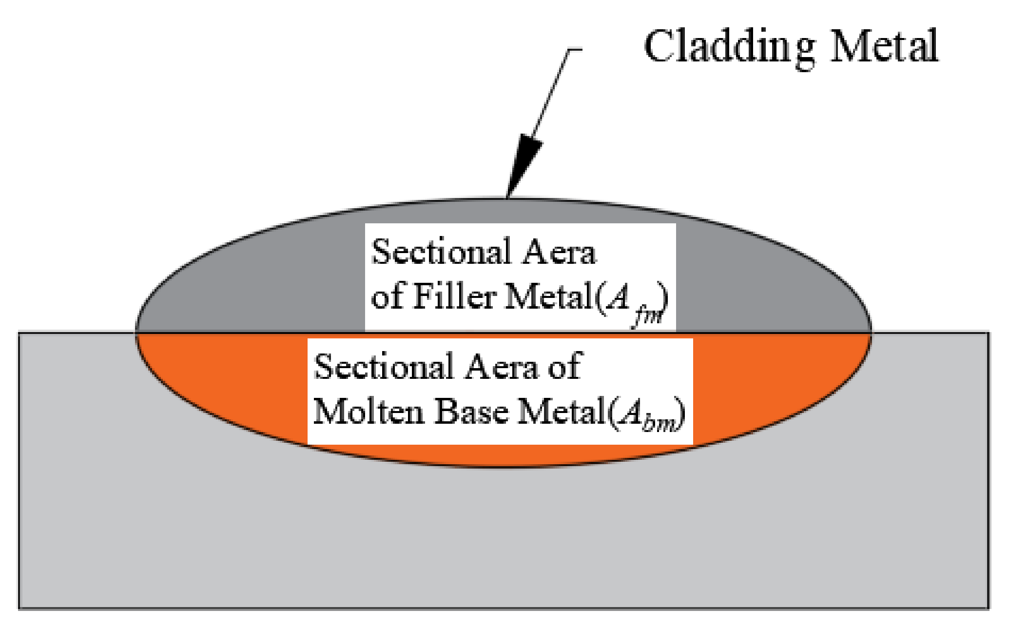
2. Weld Bead Dilution Ratio
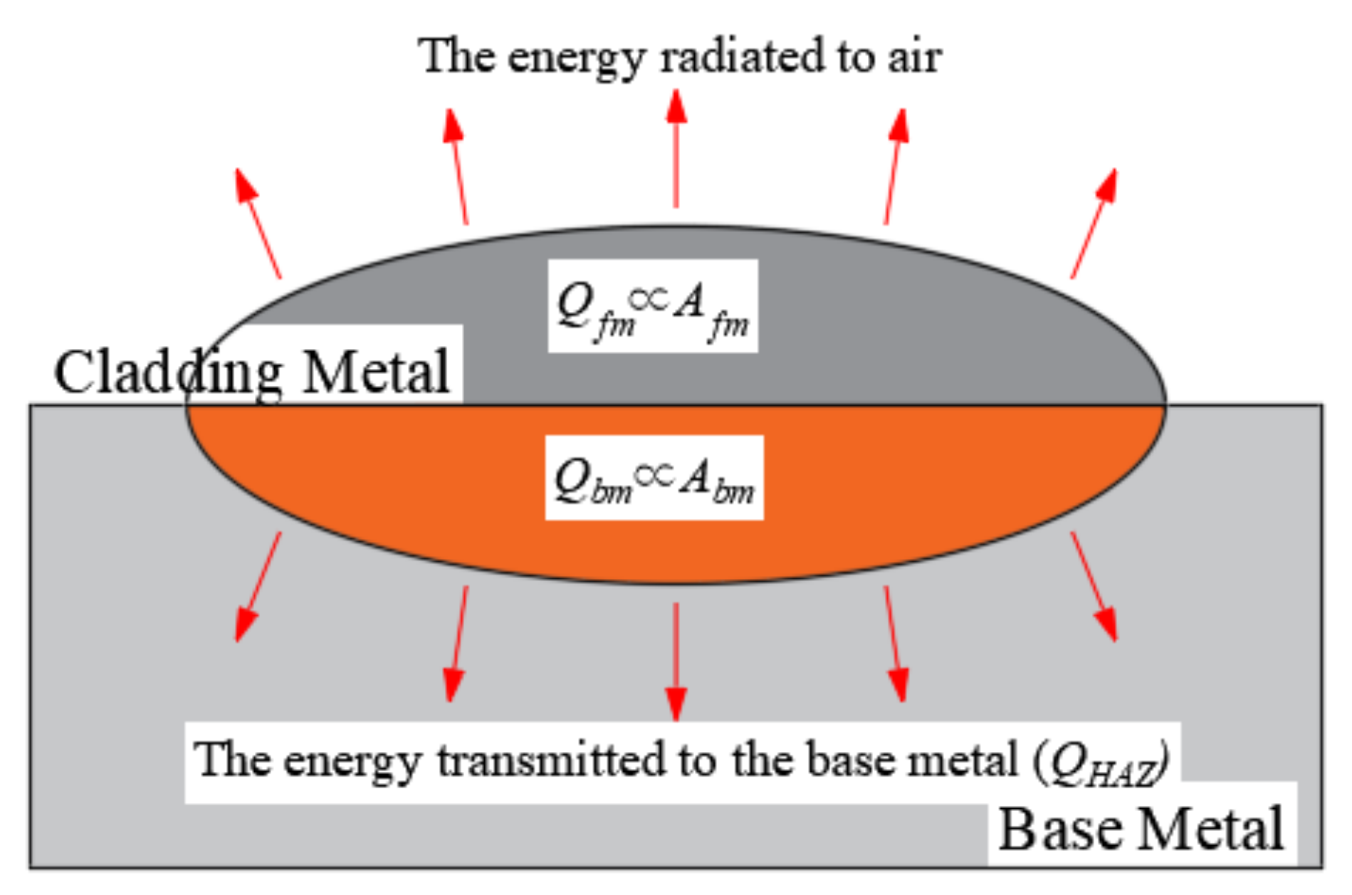
3. Base Metal Melting Efficiency
4. Materials and Experimental Procedures
5. Comparison of Measurement and Prediction Results of the Dilution Ratio under Pipeline Repair Welding Cladding Conditions
5.1. Test Design Affecting Dilution Ratio
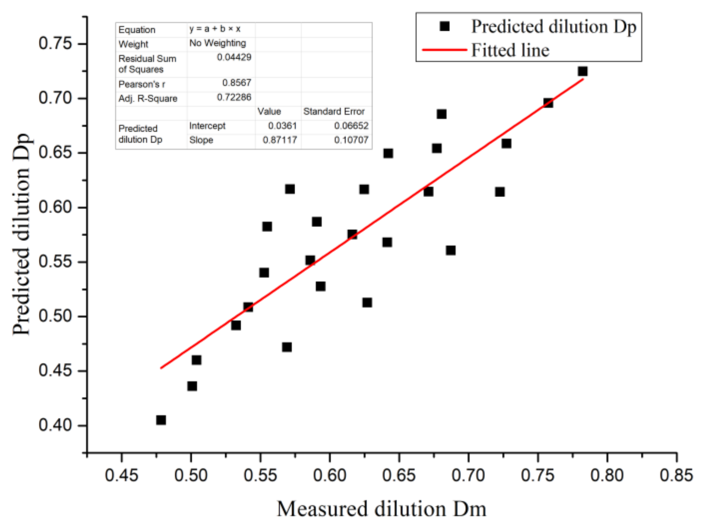
5.2. Estimation of the Dilution Ratio by the Literature
Arc Thermal Efficiency
- 1.
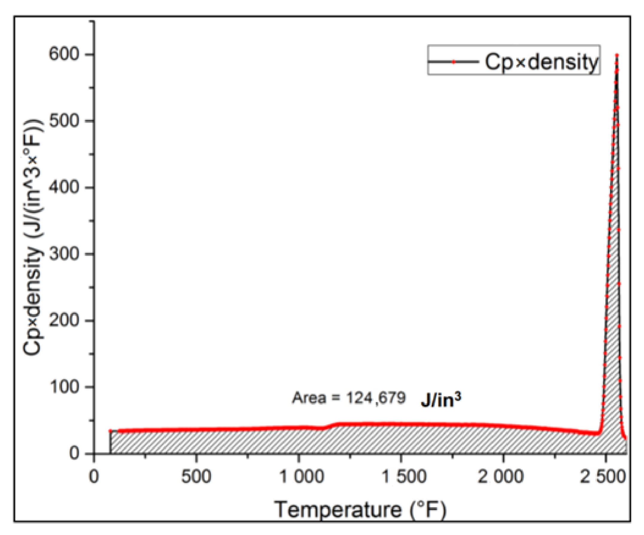
- Heat required to melt the unit volume of welding wire,
- 2.
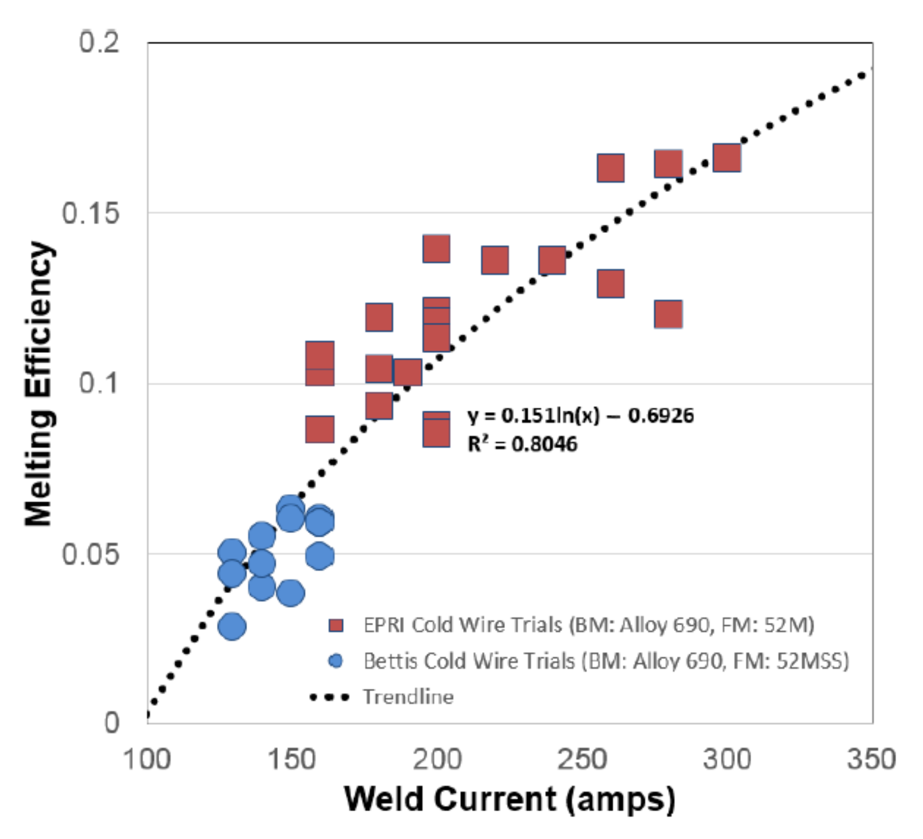
- Calculation of the base metal melting efficiency
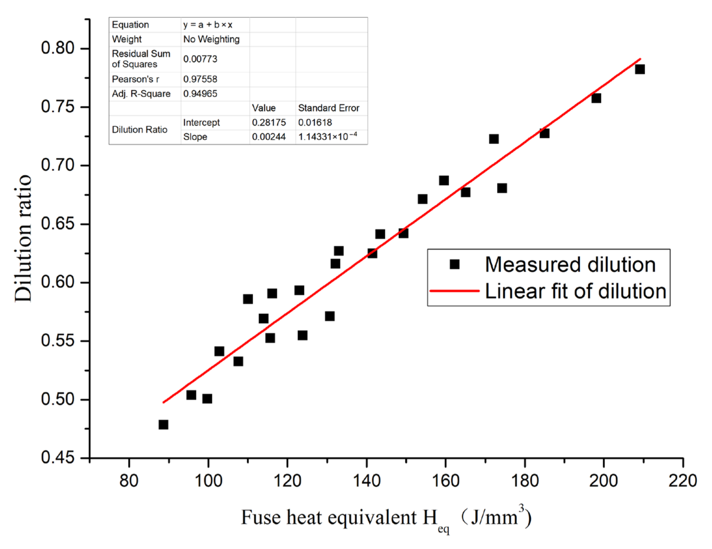
6. Prediction of the Dilution Ratio Using the Thermal Equivalent of the Fuse
- Estimation of the melting efficiency of the base metal
- 2.
- The relationship between the heat distribution ratio and the equivalent heat of the fuse
7. Discussion
7.1. Walking Speed Remains Constant, and the Pulse Line Energy Changes in Proportion to Wire Feeding Speed
7.2. Prediction of the Dilution Ratio of the Welding Speed and the Pulse Line Energy/Wire Feeding Speed
7.3. Control Strategy for Improving the Cladding Efficiency and Reducing the Dilution Ratio at the Same Time
8. Conclusions
- (1)
- The “fuse heat equivalent”, used to predict the dilution ratio of the deposited weld bead of the cladding welding of nuclear power components, is proposed. The dilution ratio of the heat power of the weld-forming unit length to the section of the fuse is predicted by the linear energy of the deposited metal-forming unit volume. Under this condition, there is a linear positive correlation between the fuse heat equivalent and the dilution ratio.
- (2)
- With the increase in the heat equivalent of the fuse, the proportion of the deposition line energy to the total effective heat input line energy decreases; the proportion of the base metal melting line energy increases; and the proportion of the non-melting line energy diffused to the base metal is basically unchanged.
- (3)
- The fuse heat equivalent is used to predict and control the dilution ratio under the condition of pulse welding. By increasing the wire feeding speed under the condition of the pulse peak current and reducing the welding travel speed, a high-deposition efficiency, low-dilution ratio and low-heat input is achieved, which plays an important guiding role in improving the deposition quality.
Author Contributions
Funding
Institutional Review Board Statement
Informed Consent Statement
Data Availability Statement
Acknowledgments
Conflicts of Interest
References
- King, C.; Frederick, G. Technical Basis for Preemptive Weld Overlays for Alloy 82/182 Butt Welds in PWRs(MPR-169) Revision 1; EPRI: Palo Alto, CA, USA, 2008. [Google Scholar]
- Xie, Y.; Wu, Y.; Burns, J.; Zhang, J. Characterization of stress corrosion cracks in Ni-based weld alloys 52, 52M and 152 grown in high-temperature water. Mater. Charact. 2016, 112, 87–97. [Google Scholar] [CrossRef]
- Li, G.; Zhang, M.; Huang, J.; Sun, Z.; Wu, Y. A comparative study on microstructure and properties of Inconel 52M overlays deposited by layer beam and GTA cladding. Int. J. Adv. Manuf. Technol. 2015, 81, 103–112. [Google Scholar] [CrossRef]
- Cai, Z.B.; Li, Z.Y.; Yin, M.G.; Zhu, M.H.; Zhou, Z.R. A review of fretting study on nuclear power equipment. Tribol. Int. 2020, 144, 106095. [Google Scholar] [CrossRef]
- Bochenek, K.; Węglewski, W.; Strojny-Nędza, A.; Pietrzak, K.; Chmielewski, T.; Chmielewski, M.; Basista, M. Microstructure, Mechanical, and Wear Properties of NiCr-Re-Al2O3 Coatings Deposited by HVOF, Atmospheric Plasma Spraying, and Laser Cladding. J. Therm. Spray Tech. 2022, 31, 1609–1633. [Google Scholar] [CrossRef]
- Kołodziejczak, P.; Golański, D.; Chmielewski, T.; Chmielewski, M. Microstructure of Rhenium Doped Ni-Cr Deposits Produced by Laser Cladding. Materials 2021, 14, 2745. [Google Scholar] [CrossRef] [PubMed]
- Mishra, A. Corrosion Study of Base Material and Welds of a Ni–Cr–Mo–W Alloy. Acta Metall. Sin. 2017, 30, 326–332. [Google Scholar] [CrossRef]
- Kołodziejczak, P.; Bober, M.; Chmielewski, T. Wear Resistance Comparison Research of High-Alloy Protective Coatings for Power Industry Prepared by Means of CMT Cladding. Appl. Sci. 2022, 12, 4568. [Google Scholar] [CrossRef]
- Chu, Y.J.; Chen, Y.; Chen, Y.X.; Liu, P.; Li, X.Q. Microstructure and corrosion Behavior of Ni-Cr-Mo Nickel-based Alloy Weld. Mater. Res. 2020, 23. [Google Scholar] [CrossRef]
- Saju, T.; Velu, M. Review on welding and fracture of nickel based superalloys. Mater. Today Proc. 2021, 46, 7161–7169. [Google Scholar] [CrossRef]
- Mao, Q.; Zhang, Y.; Liu, J.; Zhao, Y. Breaking Material Property Trade-offs via Macrodesign of Microstructure. Nano Lett. 2021, 21, 3191–3197. [Google Scholar] [CrossRef] [PubMed]
- Mao, Q.; Zhang, Y.; Guo, Y.; Zhao, Y. Enhanced electrical conductivity and mechanical properties in thermally stable fine-grained copper wire. Commun. Mater. 2021, 2, 46. [Google Scholar] [CrossRef]
- Gandy, D.W.; Findlan, S.J.; Smith, R.E.; Childs, W.J. A Better Way to Control GTA Weld Dilution, Welding Design and Fabrication. August 1992, 65, 41–43. [Google Scholar]
- Dupont, J.N.; Marder, A.R. Dilution in Single Pass Arc Welds. Metall. Mater. Trans. B 1996, 27, 481–489. [Google Scholar] [CrossRef]
- McCracken, S.L.; Smith, R.E. Hot Cracking Phenomena in Welds III; Springer: Berlin/Heidelberg, Germany, 2011; pp. 333–352. [Google Scholar]
- Balos, S.; Dramicanin, M.; Janjatovic, P.; Zabunov, I.; Pilic, B.; Goel, S.; Szutkowska, M. Suppressing the Use of Critical Raw Materials in Joining of AISI 304 Stainless Steel Using Activated Tungsten Inert Gas Welding. Metals 2019, 9, 1187. [Google Scholar] [CrossRef]
- Chiang, M.F.; Lo, T.Y.; Chien, P.H.; Chi, C.H.; Chang, K.C.; Yeh, A.C.; Shiue, R.K. The Dilution Effect in High-Power Disk Laser Welding the Steel Plate Using a Nickel-Based Filler Wire. Metals 2021, 11, 874. [Google Scholar] [CrossRef]
- Tatman, J.K.; McCracken, S.L.; Hicks, T.G. Development of new weld heat input and dilution equations for gas tungsten arc welding—Part 1. In Proceedings of the ASME 2013 Pressure Vessels and Piping Conference, Paris, France, 14–18 July 2013; pp. 14–18. [Google Scholar]
- Tatman, J.K. Development of improved equations for weld heat input and dilution control—Part 2. In Proceedings of the ASME 2018 Pressure Vessels and Piping Conference, Prague, Czech Republic, 15–19 July 2018; pp. 15–20. [Google Scholar]
- Lu, L.; Cai, Z.P.; Yang, J.; Liang, Z.X.; Sun, Q.; Pan, J.L. Study on the Hot Cracking Law of Inconel 690/52M Welding Material on F304LN Base Metal by Multi-Layer Cladding. Metals 2021, 11, 1540. [Google Scholar] [CrossRef]
- Fuerschbach, P.W.; Knorovsky, G.A. A Study of Melting Efficiency in Plasma Arc and Gas Tungsten Arc Welding. Weld. J. 1991, 70, 287s–297s. [Google Scholar]
- Collings, N.; Wong, K.Y.; Guile, A.E. Efficiency of Tungsten-Inert Gas Arcs in Very High Speed Welding. Proc. Ints. Elecr. Engr. 1979, 126, 276–280. [Google Scholar] [CrossRef]
- Lancaster, J.F. The Physics of Welding, 2nd ed.; International Institute of Welding: Oxford, UK, 1986; pp. 162–164. [Google Scholar]


| Welding Voltage/V | Peak Current/A | Welding Speed mm/min | Peak Wire Feeding Speed mm/min | Dilution Ratio | Cross Section Metallography |
|---|---|---|---|---|---|
| 8.7 | 150 | 70 | 500 | 68.72% |  |
| 8.7 | 150 | 80 | 600 | 62.70% |  |
| 8.7 | 150 | 80 | 700 | 56.91% |  |
| 8.7 | 150 | 90 | 800 | 50.09% | 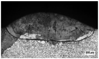 |
| 8.7 | 150 | 100 | 900 | 47.85% | 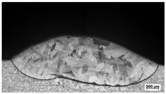 |
| 8.8 | 160 | 70 | 500 | 72.26% | 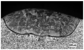 |
| 8.8 | 160 | 80 | 600 | 64.15% |  |
| 8.8 | 160 | 80 | 700 | 59.34% | 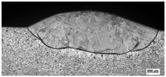 |
| 8.8 | 160 | 90 | 800 | 53.25% | 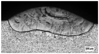 |
| 8.8 | 160 | 100 | 900 | 50.39% | 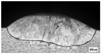 |
| 8.9 | 170 | 70 | 500 | 72.74% | 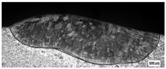 |
| 8.9 | 170 | 80 | 600 | 67.12% |  |
| 8.9 | 170 | 80 | 700 | 61.62% | 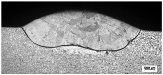 |
| 8.9 | 170 | 90 | 800 | 55.27% | 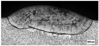 |
| 8.9 | 170 | 100 | 900 | 54.12% | 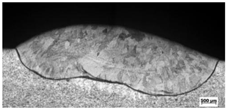 |
| 9 | 180 | 70 | 500 | 75.75% | 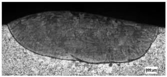 |
| 9 | 180 | 80 | 600 | 67.72% | 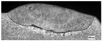 |
| 9 | 180 | 80 | 700 | 62.49% | 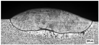 |
| 9 | 180 | 90 | 800 | 55.49% | 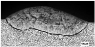 |
| 9 | 180 | 100 | 900 | 58.59% | 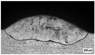 |
| 9 | 190 | 70 | 500 | 78.24% | 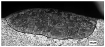 |
| 9 | 190 | 80 | 600 | 68.07% |  |
| 9 | 190 | 80 | 700 | 64.21% | 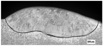 |
| 9 | 190 | 90 | 800 | 57.14% |  |
| 9 | 190 | 100 | 900 | 59.07% |  |
Publisher’s Note: MDPI stays neutral with regard to jurisdictional claims in published maps and institutional affiliations. |
© 2022 by the authors. Licensee MDPI, Basel, Switzerland. This article is an open access article distributed under the terms and conditions of the Creative Commons Attribution (CC BY) license (https://creativecommons.org/licenses/by/4.0/).
Share and Cite
Lu, L.; Cai, Z.; Yang, J.; Liang, Z.; Sun, Q.; Pan, J. Study on Key Parameters of Dilution Ratio of the Bead Deposited by GTAW Method for Nuclear Components. Metals 2022, 12, 1506. https://doi.org/10.3390/met12091506
Lu L, Cai Z, Yang J, Liang Z, Sun Q, Pan J. Study on Key Parameters of Dilution Ratio of the Bead Deposited by GTAW Method for Nuclear Components. Metals. 2022; 12(9):1506. https://doi.org/10.3390/met12091506
Chicago/Turabian StyleLu, Li, Zhipeng Cai, Jia Yang, Zhenxin Liang, Qian Sun, and Jiluan Pan. 2022. "Study on Key Parameters of Dilution Ratio of the Bead Deposited by GTAW Method for Nuclear Components" Metals 12, no. 9: 1506. https://doi.org/10.3390/met12091506