Article

Finite Element Simulation of Bending Thin-Walled Parts and Optimization of Cutting Parameters

1
School of Materials Science and Engineering, Shandong Jianzhu University, Jinan 250101, China
2
School of Mechanical and Electrical Engineering, Shandong Jianzhu University, Jinan 250101, China
*
Author to whom correspondence should be addressed.
Metals 2023, 13(1), 115; https://doi.org/10.3390/met13010115
Submission received: 12 December 2022 / Revised: 28 December 2022 / Accepted: 4 January 2023 / Published: 6 January 2023
(This article belongs to the Section Computation and Simulation on Metals)

Abstract

:
Aiming at the problems of large elastic deformation and low machining accuracy in cutting titanium alloy thin-walled parts, this paper establishes the finite element model of milling titanium alloy thin-walled parts, and simulates and analyses the milling process of titanium alloy thin-walled parts by the statics analysis module of ANSYS 15.0 software. The maximum deformation point of the workpiece in the milling process is determined. Then the combination of cutting parameters that can minimize the deformation is determined by the orthogonal experiments of four factors and four levels. This paper designs the single factor experiments, which study the distribution of the milling force and the deformation law of the parts in the milling process. Moreover, this paper carries out the optimal design of the cutting parameters by orthogonal experiments, which provides a reference for the selection of the cutting parameters for the bending thin-walled parts of titanium alloy.

1. Introduction

With the booming development of the aerospace industry, the processing accuracy of thin-walled parts is required to be higher and higher. Fukada studied the structural deterioration and reinforcement restoration of curved thin-walled structures [1]. Multi-objective optimization of cutting aluminum tubes under quasi-static load was studied in reference [2]. Hareendran studied the surface quality of thin-walled machined parts [3]. A lengthwise bending composite ultrasonic vibration-assisted milling-enhanced TC4 titanium alloy was studied by Hu et al. [4]. Khalkhali studied composite thin-wall machining [5]. However, the thin-walled part has a small amount of stiffness, which is easy to deform in processing but means it is difficult to ensure the processing accuracy [6,7,8,9,10,11]. Moreover, the processing of thin-walled parts is a big problem in the manufacturing industry [12,13,14,15,16]. Agarwal A [17] studied the machining deformation and surface quality of aero-engine blades by finite element dynamic analysis of milling methods and milling parameters, and optimized the cutting scheme. Bolar [18] predicted the machining elastic deformation of thin-walled titanium alloy parts and compensated the cutting distortion generated in the machining process through double-sided loop cutting technology, and thus eliminated the distortion of thin-walled parts and improved the machining accuracy. Abbasi, Sarwar Ali [19] studied the influence of the tool edge angle and feed direction on the machining deformation of TC4 bending thin-walled parts under finishing conditions through theoretical research, experimental verification and finite element simulation. A S Mohruni [20] adopted the DEFORM-3D point tracking method to simulate the machining process of TC4 thin-walled parts, and analyzed the influence of cutting parameters on the stability of the machining process of thin-walled parts. DU [21] studied the effect of cutting parameters on machining deformation by orthogonal analysis, and obtained the optimal combination of cutting parameters through range and advantage analysis.
Abbas [22] found through research that the increase in the thermal diffusion coefficient of porous media can cause more heat energy to disperse to the wall along the normal direction during processing. In addition, some scholars [23,24,25] have studied the thermal conductivity and other problems in the processing process. Some research results show that the introduction of a magnetic field in the reprocessing can affect the metal flow, such as the dragging flow or by generating forces opposite to the metal flow.
Aiming at the problems of large elastic deformation and low machining accuracy in cutting titanium alloy thin-walled parts, this paper establishes the finite element model of milling bending thin-walled titanium alloy parts by ANSYS finite element simulation software, and studies the influence of milling cutter position and cutting parameters on the deformation law. Moreover, this paper confirms the optimal combination of cutting parameters by orthogonal experiments, and studies the influence of each milling parameter on the machining deformation, which provides a reference for the selection of cutting parameters of titanium alloy bending parts under different machining requirements.

2. Milling Parameters and Models of Bending Thin-Walled Parts

This paper selected the part of titanium alloy Ti-6Al-4V that is 4 mm thick and 80 mm in height, the inner circle radius is 60 mm and the tool cuts on the outside of the bending thin-walled parts, as shown in Figure 1. The R-θ-Z polar coordinate system is established, the origin of which is the inner center of the circle, the Z axis is the height direction of the bending thin-walled part, the R axis is the radius direction and the counterclockwise direction of θ is the positive direction.
The Poisson’s ratio v of the thin-walled part is 0.342, the tensile strength is 920 MPa, the density is 4440 kg/m3, the elastic modulus E is 108 GPa and the yield strength is 860 MPa. The cutting tool adopts a YG8 carbide tool, which is suitable for difficult-to-process materials. The front angle of the tool is 15°, the back angle is 12°, the spiral angle is 35°, the edge number is 4, the diameter is 10 mm, the elastic modulus is 640 GPa, the Poisson’s ratio v is 0.22 and the density is 14,400–14,600 kg/m3.

2.1. Basic Steps of Finite Element Analysis for Bending Thin-Walled Parts

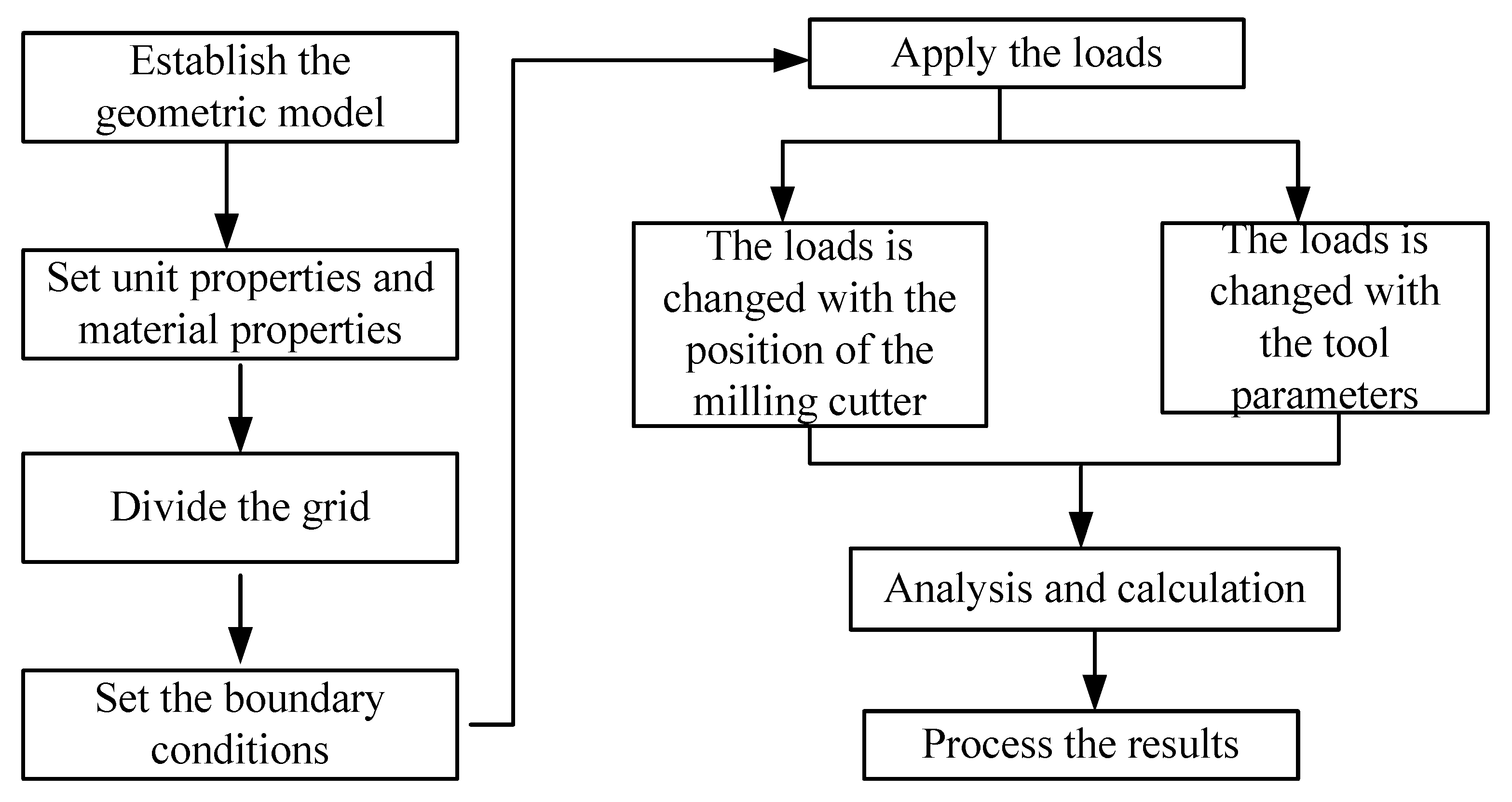
The basic flow of finite element analysis is shown in Figure 2. This paper establishes the model by ANSYS 15.0, ANSYS, Pittsburgh, PA, USA, which takes the center of the bending thin-walled part on the upper surface as the polar origin and sets the element type of the material as Solid185 element. Solid185 is used for modeling 3D solid structures. It is defined as an eight-node model with three degrees of freedom per node. This paper adopts the smart grid, and the smart sizing is 2. Boundary conditions are defined to impose full constraints on the bottom plate. The dynamic milling force is simplified as the concentrated load acting on thin-walled parts, which remains unchanged. This paper only studies the influence of the radial load on the deformation of thin-walled parts, the analysis and calculation, and then draws the conclusions [26,27,28,29].

2.2. Influence of Position Change of Milling Cutter in Circumferential Direction

This paper sets the cutting parameters as: the radial depth of cutting (ae) is 1.6 mm, axial depth of cutting (ap) is 3 mm, feed per tooth (fz) is 0.08 mm/tooth and cutting speed (vc) is 140 m/min. The cutting parameters and tool parameters are unchanged, and the cutting force is unchanged. The only changed parameter is the machining position of the tool. The radial cutting force as the main cutting force is far greater than the axial and tangential forces, so the axial and tangential forces are ignored [30]. The radial concentrated load acting on the thin-walled parts remains unchanged, keeping the radial concentrated load as 150 N. During the milling process, the force in the R direction is the radial force, which causes the radial deformation of the thin-walled parts. The force in the θ direction is tangential force, which causes the circumferential deformation of the thin-walled parts. The force in the Z direction is the axial force, which causes the axial deformation of the thin-walled parts.
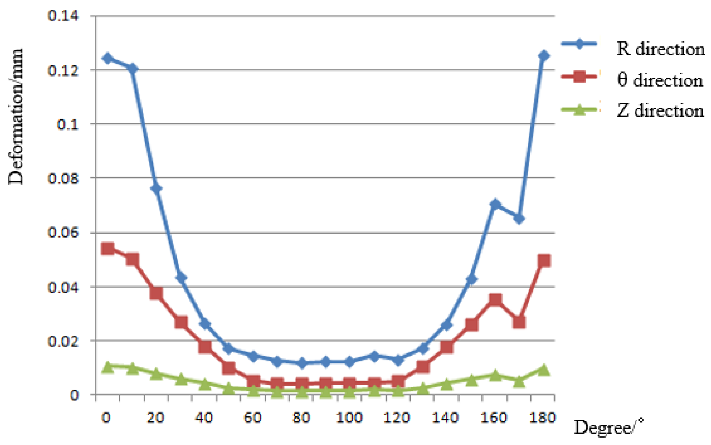
Assuming that the axial cutting depth is 7.5 mm, the machining position of the milling cutter is set at an interval of 10° from 0° to 180° in the θ direction of the outer surface of the bending thin-walled part, the radius is 62 mm and the Z direction coordinate is 72.5 mm. The deformation in the R direction with θ is shown in Figure 3. The maximum deformations in the R, θ and Z directions are 0.125523 mm, 0.054418 mm and 0.009926 mm, respectively. It can be seen that the deformation in the R direction is the most serious in the machining process. Compared with the radius and height of the thin-walled part, the thickness in the R direction is very small, which leads to the smaller stiffness of the thin-walled parts and larger deformation. Therefore, this paper mainly studies the R direction deformation. It can be seen from Figure 3 that the maximum deformation point in the circular direction of milling the workpiece is R = 62 mm, θ = 180 degrees and Z = 72.5 mm.

2.3. Analysis of Machining Deformation Results

Because the radius of the workpiece is much greater than the thickness of the thin-walled part, the length of the cutting edge of the tool is much less than the height of the workpiece. When the tool is cutting on the workpiece, the cutting force line load of the tool on the workpiece can be assumed to be a radial concentrated load. When the radial concentrated load is applied at the point R = 62 mm, θ = 180° and Z = 72.5 mm, the R direction deformation of the bending thin-walled part is as shown in Figure 4. The maximum deformation of the R direction (the radial direction) is 0.125523 mm.

2.4. Influence of the Milling Cutter Position in the Z Direction on the Deformation

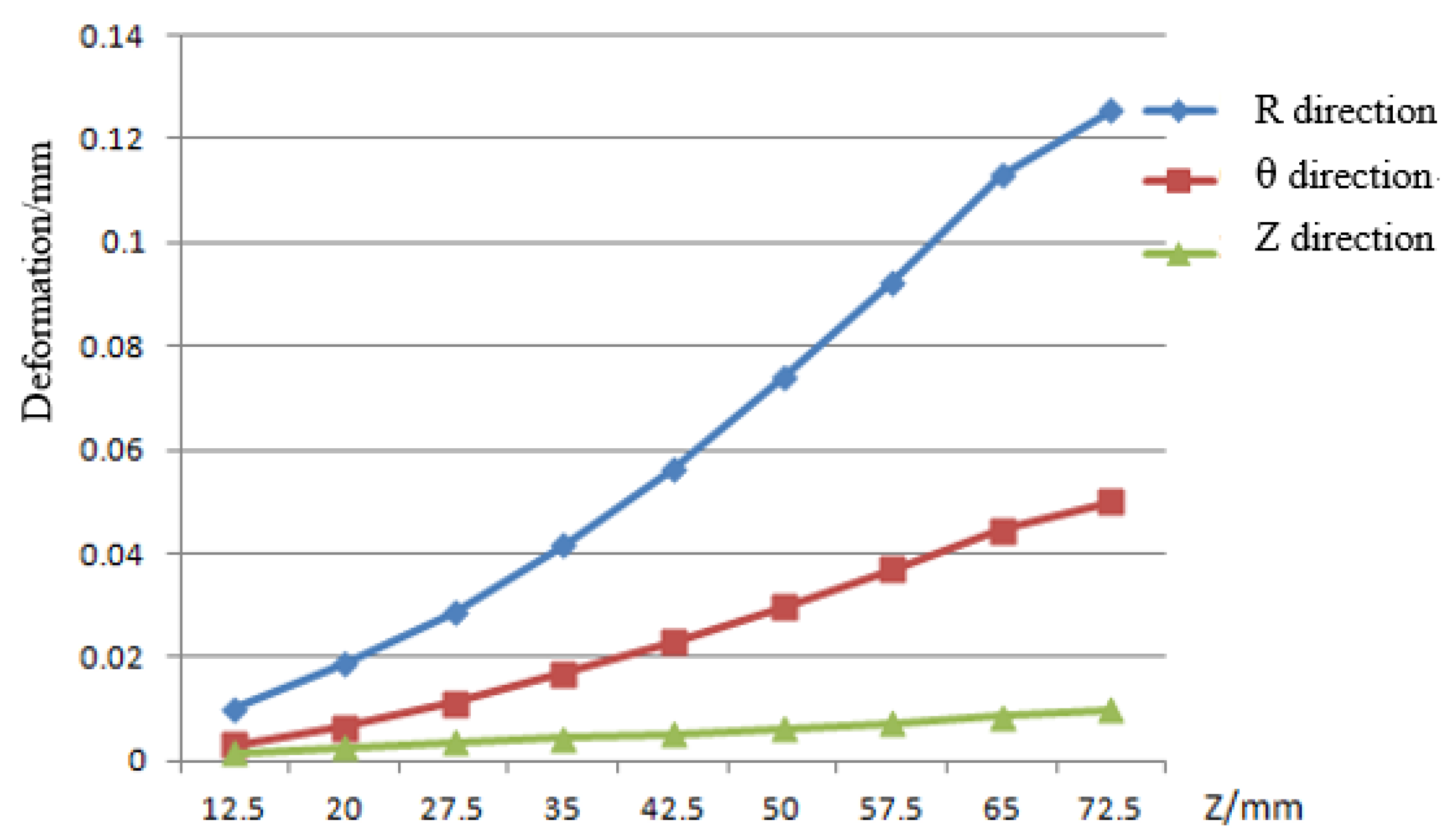
When the milling position changes every 7.5 mm in the Z direction, the Z value goes from 12.5 mm to 72.5 mm. The radius R and angle θ are unchanged, and R = 62 mm, θ = 180°. The deformation of the thin-walled parts in the R direction is shown in Figure 5.
It can be seen in Figure 5 that the deformation in the R direction is the largest in the three directions of the workpiece. The maximum deformation displacement in the R direction is 0.125523 mm, and the minimum deformation displacement is 0.010117 mm. The maximum deformation displacement in the θ direction is 0.050028 mm, and the minimum deformation displacement is 0.003022 mm. The maximum deformation displacement in the Z direction is 0.009926 mm, and the minimum deformation displacement is 0.001683 mm. Therefore, the maximum deformation point is also R = 62 mm, θ = 180° and Z = 72.5 mm. The further the machining position is from this point, the smaller the deformation of the thin plate will be.

2.5. Influence of Cutting Parameters on the Deformation at the Maximum Deformation Point by Orthogonal Experiments

Aiming at the influence of cutting parameters on the deformation, orthogonal experiments are adopted. The experimental value is the radial force Fymax, which is perpendicular to the workpiece surface. The experimental factors are the milling speed, feed per tooth, axial depth of cutting and radial depth of cutting. Four levels are taken for each factor in the experiment to constitute the orthogonal experiment of four factors and four levels. The milling speed can be reasonably selected in the range of 100–250 m/min. The axial cutting depth should be selected between 2 mm and 5 mm. Because this paper studies the maximum deformation of bending thin-walled parts in the finishing stage, according to the actual processing technology, the radial cutting depth is adopted at four levels: 0.8 mm, 1 mm, 1.2 mm and 1.4 mm, and the feed per tooth is adopted at four levels: 0.08 mm/tooth, 0.1 mm/tooth, 0.12 mm/z and 0.14 mm/z. Therefore, the factor level table of four factors and four levels is shown in Table 1. The radial milling force of each experiment group is calculated according to the empirical Formula (1) of milling force [28].
Fymax = 368.2ap0.4308ae1.2163fz0.7801vc0.0088
A total of 16 groups of simulation experiments were carried out using the above finite element simulation process. The radial deformation influences on the maximum machining deformation points under different cutting parameters were calculated, as shown in Table 2.
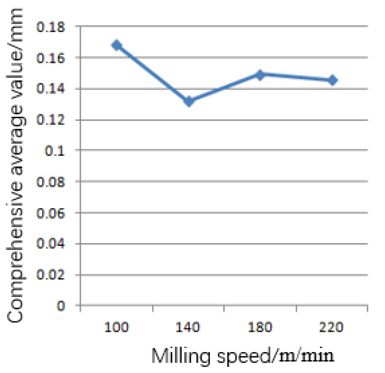
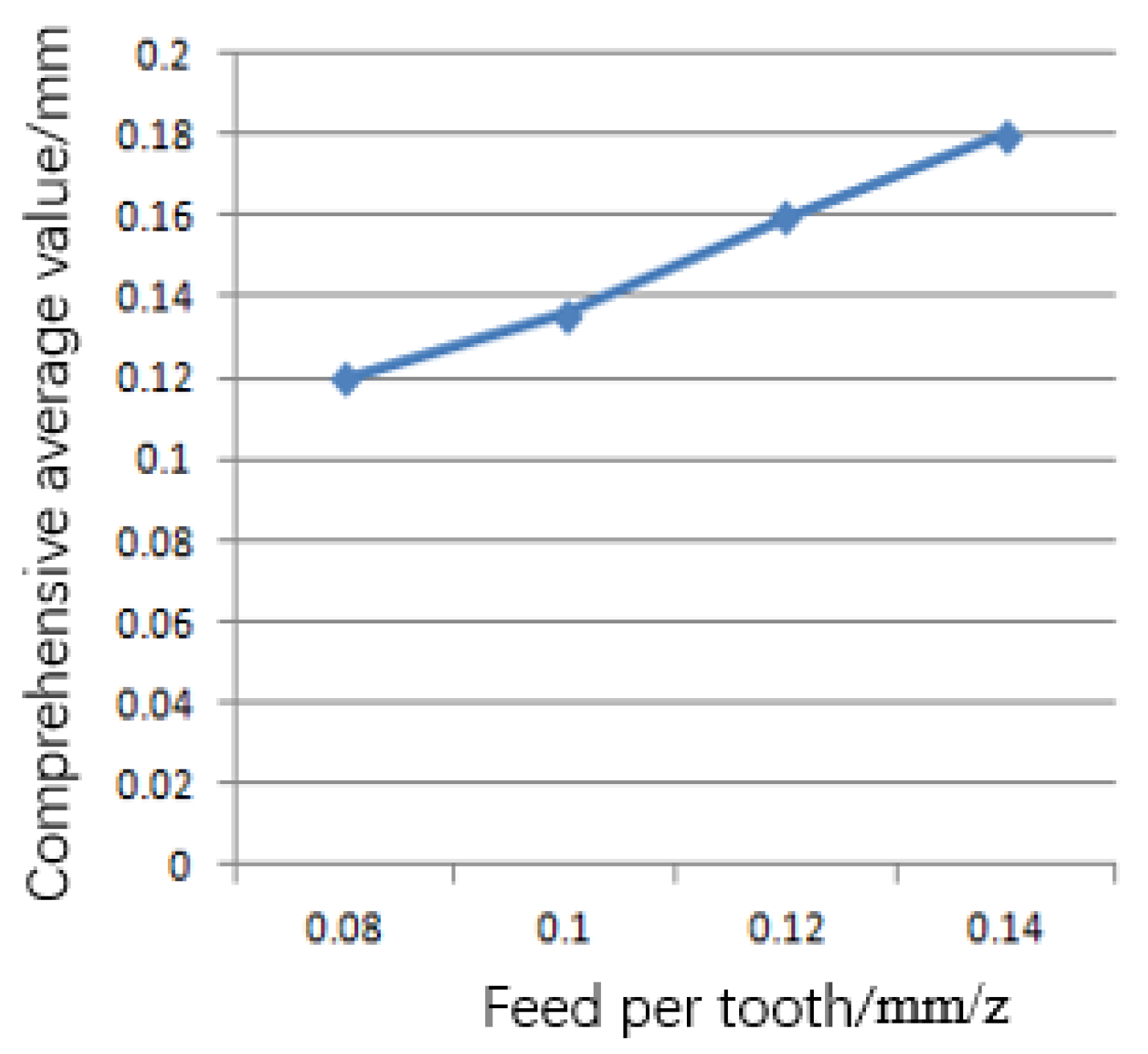
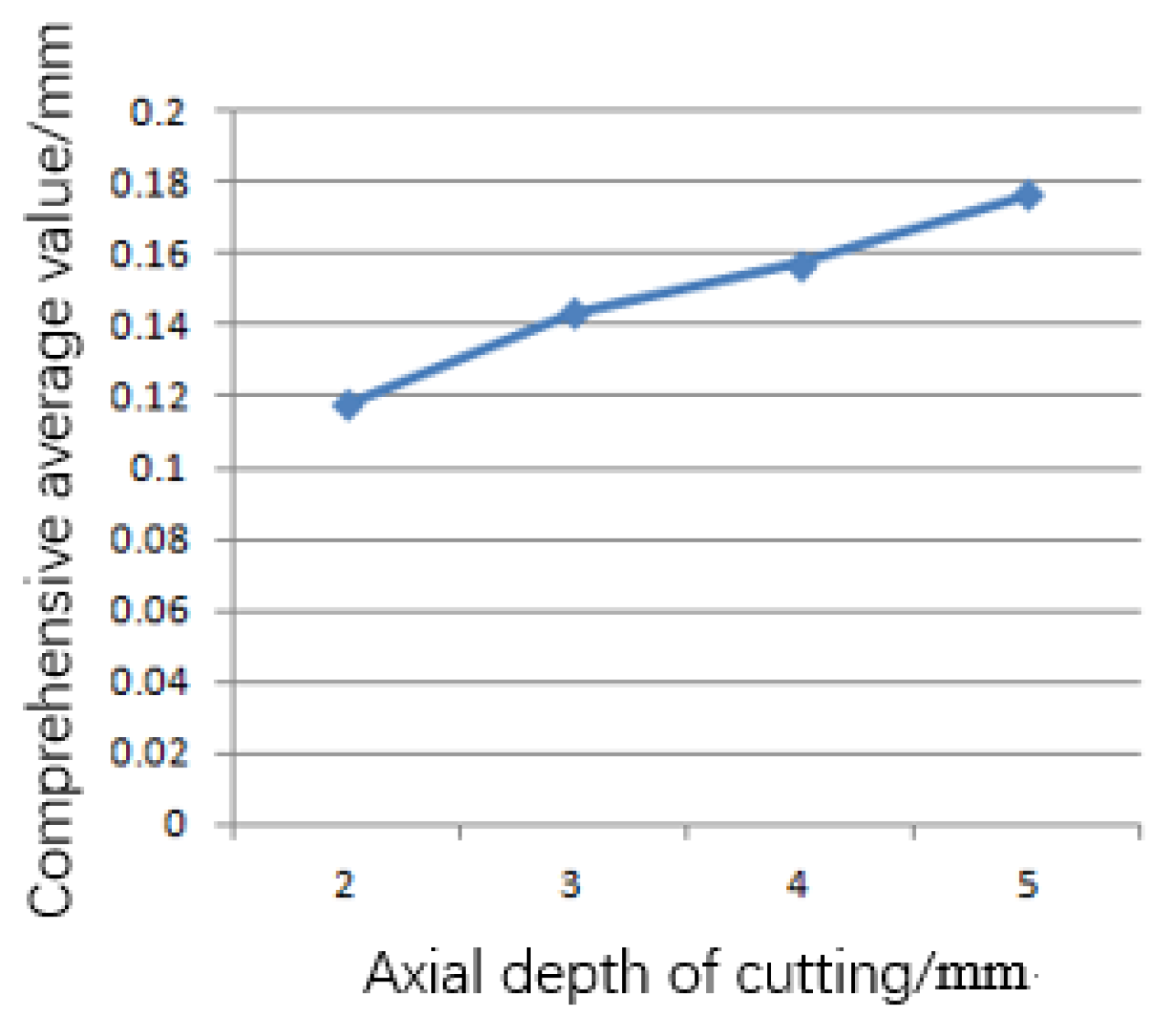
Since a single experimental index cannot fully reflect the influence of the cutting parameters on the milling deformation of thin-walled parts, this paper designs four orthogonal experimental indexes [9], which are a multi-index orthogonal experiment. It is necessary to comprehensively consider the results of the multi-index orthogonal experiment from all aspects, in order to obtain the most satisfying experiment scheme as far as possible, and to summarize the sequence and optimal combination of factors affecting the index [10]. In this experiment, the range (T) of the comprehensive average (K) is the main factor influencing the deformation. Because there are four influencing factors in this experiment, the comprehensive average values are K1, K2, K3 and K4, which, respectively, represent the influence of the milling speed vc, feed per tooth fz, axial depth of cutting ap and radial depth of cutting ae on the machining deformation. These are calculated by adding the amount of cutting deformation caused by the four levels corresponding to each factor, and dividing by four. Range is the difference between the maximum value and the minimum value of the comprehensive average in the four levels corresponding to each factor. The larger the difference is, the more obvious the influence of the factor on the machining deformation of thin-walled parts. As shown in Table 3, the one with the largest range T is the main factor, and then the combination with the minimum comprehensive average of all factors is selected as the optimal combination. The influences of the milling speed vc, feed per tooth fz, axial depth of cutting ap and radial depth of cutting ae on the deformation of bending thin-walled parts are shown in Figure 6, Figure 7, Figure 8 and Figure 9.
According to the data in Table 3, within a reasonable parameter range, the factors affecting the milling deformation of thin-walled parts are as follows: radial depth of cutting > feed per tooth > axial depth of cutting > milling speed. As can be seen from Figure 6, Figure 7, Figure 8 and Figure 9, with the increase in milling speed, the comprehensive average deformation of the bending thin-walled parts decreases first and then increases, which is mainly because the deformation of the bending thin-walled parts is the result of the combined action of the cutting force and cutting heat. At the beginning of cutting, the cutting heat is mainly carried away by the chips. With the progress in cutting, some chips are carried away, most of which mainly act on the tool and thin-walled parts, leading to the increase in the maximum deformation [11]. The maximum deformation increases with the increase in the feed rate, radial depth of cutting and axial depth of cutting. Therefore, the horizontal combination that minimizes the comprehensive average value of each factor is as follows: the milling speed vc = 140 m/min, the feed of each tooth fz = 0.08 mm/tooth, the axial depth of cutting ap = 2 mm and the radial depth of cutting ae = 0.8 mm. With this combination, the milling deformation of the thin-walled parts is the minimum, which is the optimal combination. This part of the process and the results can be compared with the literature [12], which has certain reference value.

3. Single Factor Experiments in the Influence of Cutting Parameters on Machining Deformation

On the basis of the optimal cutting parameters selected by the orthogonal experiments, the influences of the main cutting parameters on radial machining deformation were studied by changing the milling speed, feed per tooth, axial depth of cutting and radial depth of cutting successively. The cutting parameters are shown in Table 4.
The first group is the optimal cutting parameters’ combination obtained by the orthogonal experiment, and groups 2–13 are the parameter combinations obtained by successively changing the milling speed, feed per tooth, axial depth of cutting and radial depth of cutting on the basis of the first group. On the basis of the first group of the experiment, the effects of various parameters on the cutting deformation were studied.

3.1. Influence of Milling Speed on Machining Deformation

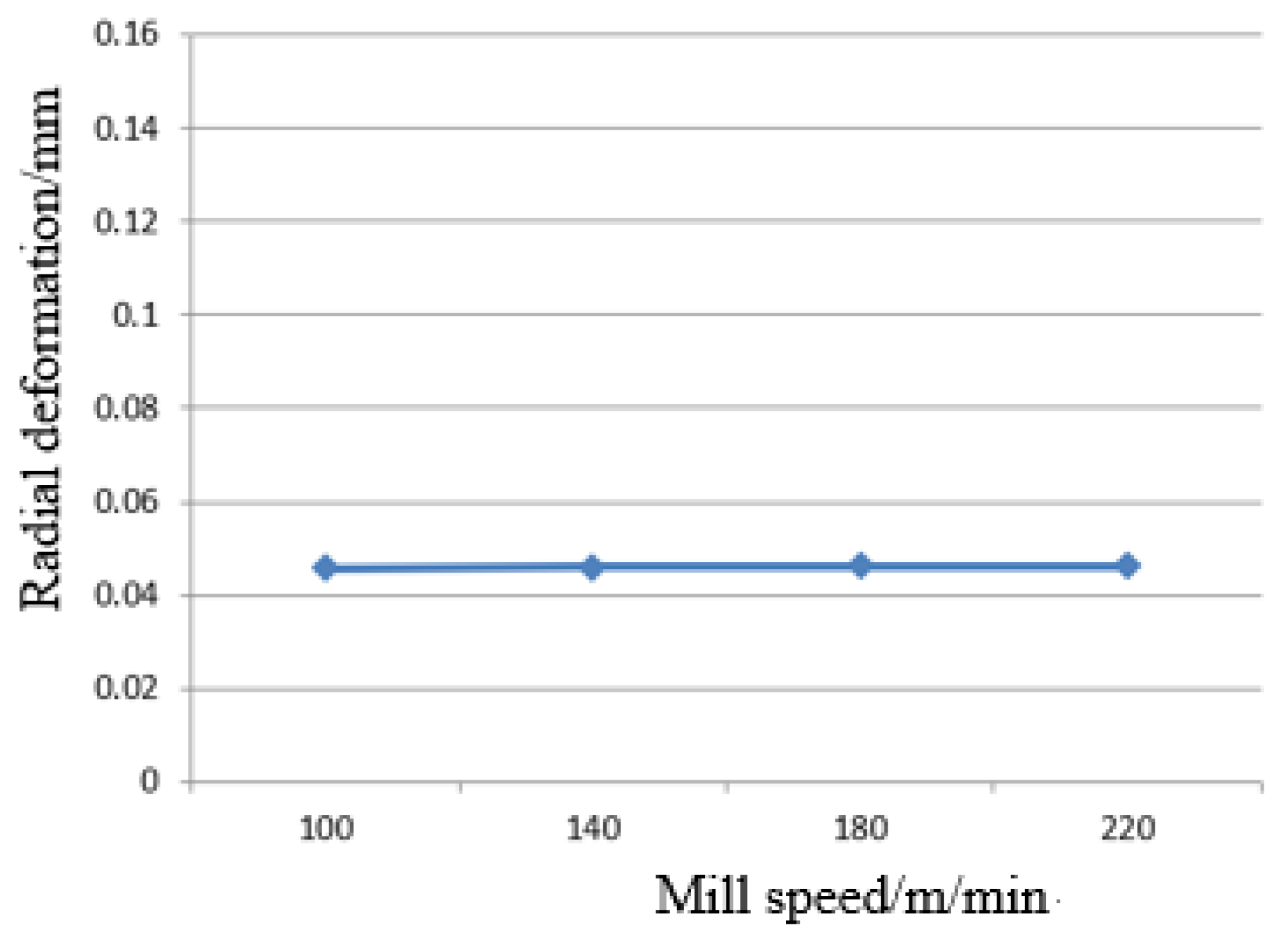
As can be seen in Table 4 and Figure 10, the radial deformation of the bending thin-walled parts hardly changes when the milling speed varies from 100 m/min to 220 m/min. This is mainly because the milling speed selected in this paper is in the high speed cutting range, so the milling speed in this range has almost no influence on the machining deformation of the bending thin-walled parts.

3.2. Influence of Feed per Tooth on Machining Deformation

As shown in Table 4 and Figure 11, when the f feed per tooth changes from 0.08 mm to 0.1 mm, the radial deformation of the bending thin-walled part increases by about 19%. When the feed per tooth changes from 0.1 mm to 0.12 mm, the radial deformation increases by about 15%. That is, the feed per tooth is proportional to the radial deformation, and the deformation increase trend gradually slows down, which is mainly because the increase in the feed per tooth leads to the increase in the cutting area and cutting force [13]. Thus, in the actual process of processing, it can be considered to reduce the feed per tooth, which not only ensures the accuracy of the product but also improves the production efficiency.

3.3. Influence of Axial Depth of Cutting on Machining Deformation

According to Table 4 and Figure 12, the axial depth of cutting is proportional to the radial deformation, which is because the increase in the axial depth of cutting leads to the increase in the cutting force. When the axial depth of cutting increases from 2 mm to 3 mm, the radial machining deformation increases by 19%. When the axial depth of cutting increases from 3 mm to 4 mm, the radial deformation increases by 13%. When the axial depth of cutting increases from 4 mm to 5 mm, the radial deformation increases by 10%. With the increase in the axial depth of cutting, the increase trend of radial deformation slows down.

3.4. Influence of Radial Depth of Cutting on Machining Deformation

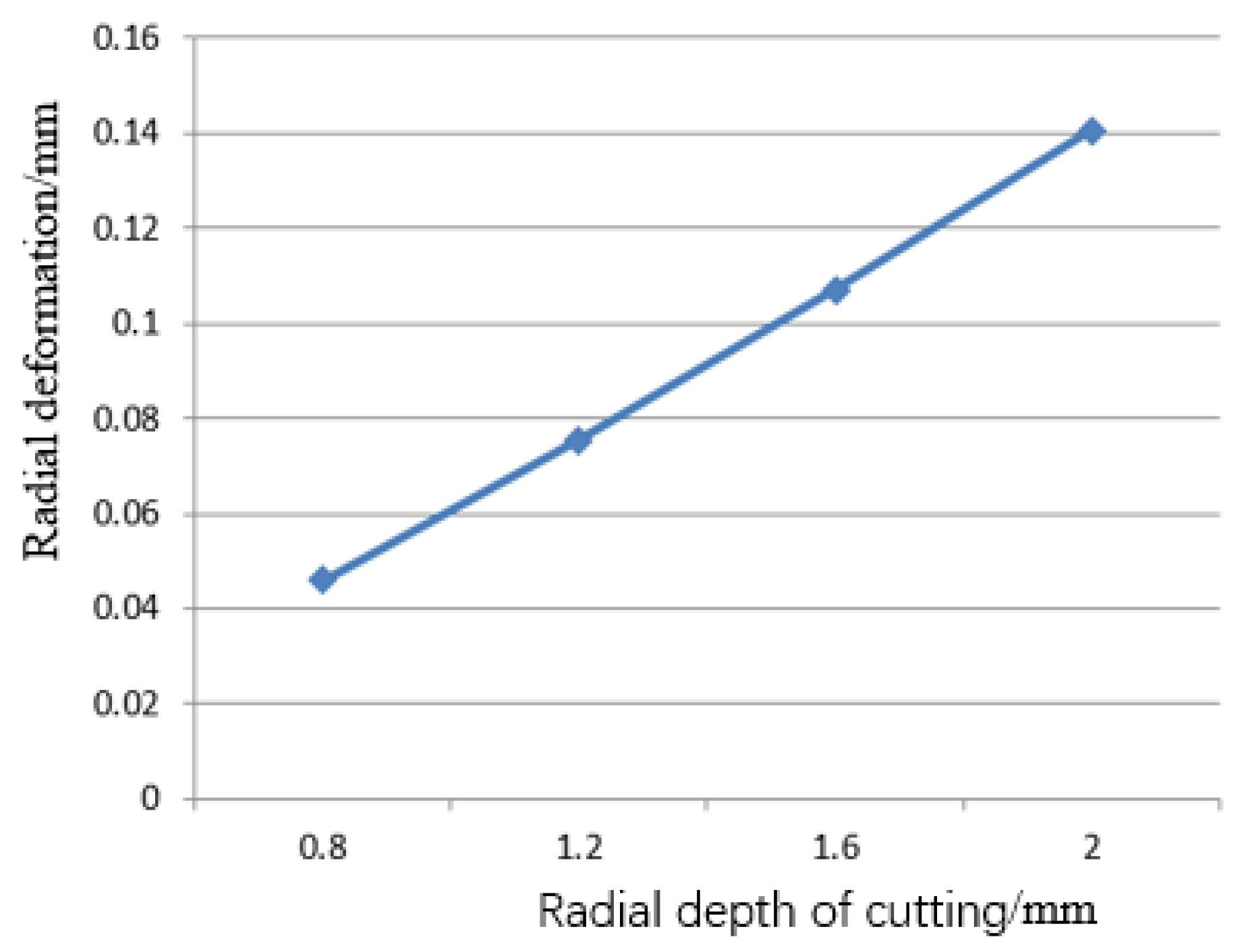
It can be seen in Table 4 and Figure 13 that the radial cutting depth has a great influence on machining deformation. A large radial depth of cutting generates a large cutting force. When the radial depth of cutting increases from 0.8 mm to 1.2 mm, the radial deformation of the bending thin-walled parts increases by 64%. When the radial depth of cutting increases from 1.2 mm to 1.6 mm, the radial deformation increases by 41%. When the radial depth of cutting increases from 1.6 mm to 2.0 mm, the radial deformation increases by 31%. Therefore, the radial depth of cutting is the main factor affecting the machining accuracy of the thin-walled parts. With the increase in the radial depth of cutting, the machining deformation of the bending thin-walled parts increases clearly. Therefore, in the actual process of machining, it is very important to choose a reasonable radial depth of cutting.

4. Conclusions

In this paper, the milling conditions of bending thin-walled parts are described firstly, and then the influence of the milling cutter position and cutting parameters on the deformation law is studied by using finite element simulation.
(1)
The maximum deformation point is determined to be R = 62 mm, θ = 180 degrees and Z = 72.5 mm, and the maximum radial deformation is 3.13%. Thus, it should be as far away from the point as possible in the process of machining.
(2)
Through orthogonal experiments, the optimal cutting parameter combination was selected as vc = 140 m/min, fz = 0.08 mm/tooth, ap = 2 mm and ae = 0.8 mm. Finally, the influence of each milling parameter on the machining deformation was studied.
(3)
The research shows that the radial depth of cutting has the greatest influence on the deformation of bending thin-walled parts, followed by the axial depth of cutting and the feed per tooth. The milling speed has little influence on the machining deformation of bending thin-walled parts.
This paper studied the processing deformation law of the bending thin-walled parts of titanium alloy by finite element simulation. Due to the limitations of time and capacity, the corresponding experiments were not verified. The following fields still need to be studied further:
(1)
In order to further reduce the deformation of bending thin-walled parts in the milling process, the cutting heat and tool wear between the tool and the workpiece in the milling process will be studied.
(2)
According to the shape characteristics of the parts, more scientific and reasonable clamping and supporting methods of bending thin-walled parts will be designed to control the deformation of parts.

Author Contributions

M.H.: data curation, formal analysis, writing—original draft preparation and funding acquisition. T.A.: conceptualization, methodology, review and editing, funding acquisition. X.S.: data curation, methodology. L.T.: investigation, methodology and software. All authors have read and agreed to the published version of the manuscript.

Funding

This study was financially supported by the National Natural Science Foundation of China (Grant No. 52275447), the Major Project of the Science and Technology Enterprise Innovation Program of Shandong Province, China (Grant No. 2022TSGC2108 and 2022TSGC2402), the Shandong Graduate Education and Teaching Reform Research Project (Grant No. SDYJG21169), the National College Student Innovation and Entrepreneurship Program (Grant No. 202210430010 and 202210430008) and the High quality curriculum construction project of Shandong Jianzhu University graduate education(YZKC202210 and ALK202210).

Data Availability Statement

The data presented in this study are available on request from the corresponding author.

Conflicts of Interest

The authors declare no conflict of interest.

References

  1. Fukada, Y.; Minagawa, H.; Nakazato, C.; Nagatani, T. Structural deterioration of curved thin-walled structure and recovery by rib installation: Verification with structural optimization algorithm. Thin-Walled Struct. 2018, 123, 441–451. [Google Scholar] [CrossRef]
  2. Guan, W.; Gao, G.; Li, J.; Yu, Y. Crushing analysis and multi-objective optimization of a cutting aluminium tube absorber for railway vehicles under quasi-static loading. Thin-Walled Struct. 2018, 123, 395–408. [Google Scholar] [CrossRef]
  3. Hareendran, M.; Sreejith, S. A study on surface quality of thin-walled machined parts. Mater. Today Proc. 2018, 5, 18730–18738. [Google Scholar] [CrossRef]
  4. Hu, W.; Du, P.; Qiu, X.; Zhao, X.; Hu, Z.; Zhang, J.; Liu, Y. Enhanced dry machinability of TC4 titanium alloy by longitudinal-bending hybrid ultrasonic vibration-assisted milling. J. Clean. Prod. 2022, 379, 134866. [Google Scholar] [CrossRef]
  5. Khalkhali, A.; Miandoabchi, E. The application of equivalent modeling of joints for bending simulation of hybrid alumi-num/high strength steel thin-walled sections joined by clinching. Thin-Walled Struct. 2020, 157, 107089. [Google Scholar] [CrossRef]
  6. Li, H.; Shi, K.-P.; Yang, H.; Tian, Y.-L. Springback law of thin-walled 6061-T4 Al-alloy tube upon bending. Trans. Nonferrous Met. Soc. China 2012, 22, s357–s363. [Google Scholar] [CrossRef]
  7. Li, Y.; Gao, T.; Zhou, Q.; Chen, P.; Yin, D.; Zhang, W. Layout design of thin-walled structures with lattices and stiffeners using multi-material topology optimization. Chin. J. Aeronaut. 2022. [Google Scholar] [CrossRef]
  8. Liu, G.; Xie, J.; Xie, S. Experimental and numerical investigations of a new U-shaped thin plate energy absorber subjected to bending and friction. Thin-Walled Struct. 2017, 115, 215–224. [Google Scholar] [CrossRef]
  9. Liu, Y.; Wu, B.; Luo, M.; Zhang, D. Modeling and Cutting Path Optimization of Shallow Shell Considering its Varying Dynamics During Machining. Procedia CIRP 2015, 31, 521–526. [Google Scholar] [CrossRef] [Green Version]
  10. Lu, F.; Zhou, G.; Zhang, C.; Liu, Y.; Chang, F.; Xiao, Z. Energy-efficient multi-pass cutting parameters optimisation for aviation parts in flank milling with deep reinforcement learning. Robot. Comput. Manuf. 2023, 81, 102488. [Google Scholar] [CrossRef]
  11. Ma, J.-W.; He, G.-Z.; Liu, Z.; Qin, F.-Z.; Chen, S.-Y.; Zhao, X.-X. Instantaneous cutting-amount planning for machining deformation homogenization based on position-dependent rigidity of thin-walled surface parts. J. Manuf. Process. 2018, 34, 401–411. [Google Scholar] [CrossRef]
  12. Ratchev, S.; Nikov, S.; Moualek, I. Material removal simulation of peripheral milling of thin wall low-rigidity structures using FEA. Adv. Eng. Softw. 2004, 35, 481–491. [Google Scholar] [CrossRef]
  13. Ringgaard, K.; Mohammadi, Y.; Merrild, C.; Balling, O.; Ahmadi, K. Optimization of material removal rate in milling of thin-walled structures using penalty cost function. Int. J. Mach. Tools Manuf. 2019, 145, 103430. [Google Scholar] [CrossRef]
  14. Shi, J.; Song, Q.; Liu, Z.; Wan, Y. Formulating a numerically low-cost method of a constrained layer damper for vibration sup-pression in thin-walled component milling and experimental validation. Int. J. Mech. Sci. 2017, 128–129, 294–311. [Google Scholar] [CrossRef]
  15. Tehranizadeh, F.; Berenji, K.R.; Yıldız, S.; Budak, E. Chatter stability of thin-walled part machining using special end mills. CIRP Ann. 2022, 71, 365–368. [Google Scholar] [CrossRef]
  16. Totis, G.; Sortino, M. Superior optimal inverse filtering of cutting forces in milling of thin-walled components. Measurement 2023, 206, 112227. [Google Scholar] [CrossRef]
  17. Agarwal, A.; Desai, K. Predictive framework for cutting force induced cylindricity error estimation in end milling of thin-walled components. Precis. Eng. 2020, 66, 209–219. [Google Scholar] [CrossRef]
  18. Bolar, G.; Das, A.; Joshi, S.N. Measurement and analysis of cutting force and product surface quality during end-milling of thin-wall components. Measurement 2018, 121, 190–204. [Google Scholar] [CrossRef]
  19. Abbasi, S.A.; Feng, P.; Ma, Y.; Cai, X.; Yu, D.; Wu, Z. Influence of tool inclination angle and cutting direction on long thin-walled part’s dimensional and geometric accuracy when high-speed ball end milling the heat-treated titanium alloy Ti–6Al–4 V. Proc. Inst. Mech. Eng. Part C J. Mech. Eng. Sci. 2016, 230, 2676–2698. [Google Scholar] [CrossRef]
  20. Mohruni, A.S.; Zahir, M.; Yanis, M.; Sharif, S.; Yani, I. Investigation of Finite Element Modelling on Thin-Walled Machining of Ti6Al4V using DEFORM-3D. J. Phys. Conf. Ser. 2019, 1167, 012002. [Google Scholar] [CrossRef]
  21. Du, J.; Long, X. Chatter suppression for milling of thin-walled workpieces based on active modal control. J. Manuf. Process. 2022, 84, 1042–1053. [Google Scholar] [CrossRef]
  22. Abbas, I.A.; El-Amin, M.; Salama, A. Effect of thermal dispersion on free convection in a fluid saturated porous medium. Int. J. Heat Fluid Flow 2009, 30, 229–236. [Google Scholar] [CrossRef]
  23. Sheikholeslami, M.; Ellahi, R. Three dimensional mesoscopic simulation of magnetic field effect on natural convection of nanofluid. Int. J. Heat Mass Transf. 2015, 89, 799–808. [Google Scholar] [CrossRef]
  24. Abbas, I.A.; Abo-Dahab, S.M. On the Numerical Solution of Thermal Shock Problem for Generalized Magneto-Thermoelasticity for an Infinitely Long Annular Cylinder with Variable Thermal Conductivity. J. Comput. Theor. Nanosci. 2014, 11, 607–618. [Google Scholar] [CrossRef]
  25. Hamzah, H.K.; Ali, F.H.; Hatami, M.; Jing, D.; Jabbar, M.Y. Magnetic nanofluid behavior including an immersed rotating conductive cylinder: Finite element analysis. Sci. Rep. 2021, 11, 1–21. [Google Scholar] [CrossRef]
  26. Xia, Q.; Gillespie, D.R.H. Quasi-static finite element modelling of thermal distribution and heat partitioning for the mul-ti-component system of high speed metal cutting. J. Mater. Process. Technol. 2020, 275, 116389. [Google Scholar] [CrossRef]
  27. Xiang, J.; Yi, J. Deformation mechanism in wax supported milling of thin-walled structures based on milling forces stability. CIRP J. Manuf. Sci. Technol. 2021, 32, 356–369. [Google Scholar] [CrossRef]
  28. Yang, Y.; Zhang, W.-H.; Ma, Y.-C.; Wan, M. Chatter prediction for the peripheral milling of thin-walled workpieces with curved surfaces. Int. J. Mach. Tools Manuf. 2016, 109, 36–48. [Google Scholar] [CrossRef]
  29. Yuan, X.; Wang, S.; Mao, X.; Liu, H.; Liang, Z.; Guo, Q.; Yan, R. Forced vibration mechanism and suppression method for thin-walled workpiece milling. Int. J. Mech. Sci. 2022, 230, 107553. [Google Scholar] [CrossRef]
  30. Zhang, H.; Hu, Y. Influence of pressure die s boosting on forming quality in bending process of thin-walled tube. Int. J. Press. Vessel. Pip. 2022, 196, 104612. [Google Scholar] [CrossRef]
Figure 1. Cutting the bending thin-walled part model.
Metals 13 00115 g001
Figure 2. Finite element analysis flow chart.
Metals 13 00115 g002
Figure 3. Deformation in three directions at different machining positions.
Metals 13 00115 g003
Figure 4. R direction deformation at the maximum deformation point.
Metals 13 00115 g004
Figure 5. Deformation in three directions with the position change of the milling in Z direction.
Metals 13 00115 g005
Figure 6. Influence on deformation of different milling speeds.
Metals 13 00115 g006
Figure 7. Influence on deformation of different feeds per tooth.
Metals 13 00115 g007
Figure 8. Influence on deformation of different axial cutting depths.
Metals 13 00115 g008
Figure 9. Influence on deformation of different radial cutting depths.
Metals 13 00115 g009
Figure 10. Influence of milling speed on radial deformation.
Metals 13 00115 g010
Figure 11. Influence of feed per tooth on machining deformation.
Metals 13 00115 g011
Figure 12. Influence of axial depth of cutting on machining deformation.
Metals 13 00115 g012
Figure 13. Influence of radial depth of cutting on machining deformation.
Metals 13 00115 g013
Table 1. Level table of factors.
FactorsMilling Speed vc
(m/min)
Feed per Tooth
fz
(mm/tooth)
Axial Depth of Cutting ap (mm)Radial Depth of Cutting ae (mm)
11000.0820.8
21400.131.2
31800.1241.6
42000.1452
Table 2. Orthogonal experiments’ design table and results.
No.Milling Speed vc (m/min)Feed per Tooth fz (mm/tooth)Axial Depth of Cutting ap (mm)Radial Depth of Cutting ae (mm)Milling Force Fymax (N)Maximum Radial Deformation (mm)
11000.0820.8560.046862
21000.131.21330.111297
31000.1241.62470.206694
41000.14523690.308786
51400.0831.61580.132217
61400.1221830.153138
71400.1250.81010.084519
81400.1441.21890.158159
91800.08422310.193305
101800.151.62460.205857
111800.1221.21270.106276
121800.1430.81090.091213
132200.0851.21280.107113
142200.140.8860.071966
152200.12322870.240167
162200.1421.61950.16318
Table 3. Range analysis of each factor in orthogonal experiment.
Comprehensive Average ValueMilling SpeedFeed per ToothAxial Depth of CuttingRadial Depth of Cutting
K10.16840.11990.0080.07364
K20.1320.13560.14370.12
K30.14920.15940.15750.17699
K40.14560.180.17660.2238
T0.03640.06010.0520.15016
Table 4. Table of cutting parameters.
No.Milling Speed vc (m/min)Feed per Tooth fz (mm/tooth)Axial Depth of Cutting ap (mm)Radial Depth of Cutting ae (mm)Radial Force Fymax (N)Radial Deformation (mm)
11000.0820.854.90.045941
21400.0820.8550.046025
31800.0820.855.20.046192
42200.0820.855.30.046276
51400.120.865.540.054845
61400.1220.875.5550.063226
71400.1420.885.210.071305
81400.0830.865.570.05485
91400.0840.874.20.062092
101400.0850.881.70.068368
111400.0821.290.20.075481
121400.0821.6127.940.107113
131400.0822167.830.140443
Disclaimer/Publisher’s Note: The statements, opinions and data contained in all publications are solely those of the individual author(s) and contributor(s) and not of MDPI and/or the editor(s). MDPI and/or the editor(s) disclaim responsibility for any injury to people or property resulting from any ideas, methods, instructions or products referred to in the content.