Abstract
This paper investigates the interaction of edge dislocations with voids in concentrated solid solution alloys (CSAs) using atomistic simulations. The simulation setup consists of edge dislocations with different periodicity lengths and a periodic array of voids as obstacles to dislocation motion. The critical resolved shear stress (CRSS) for dislocation motion is determined by static simulations bracketing the applied shear stress. The results show that shorter dislocation lengths and the presence of voids increase the CRSS for dislocation motion. The dislocation–void interaction is found to follow an Orowan-like mechanism, where partial dislocation arms mutually annihilate each other to overcome the void. Solute strengthening produces a ‘friction stress’ that adds to the Orowan stress. At variance with classical theories of solute pinning, this stress must be considered a function of the dislocation line length, in line with the idea that geometrical constraints synergetically enhance the pinning action of solutes. Modifying the equation by Bacon, Kocks and Scattergood for void strengthening to account for the solute hardening in CSAs allows one to quantitatively predict the CRSS in the presence of voids and its dependency on void spacing. The predictions show good agreement with the simulation data without invoking any fit parameters.
1. Introduction
Traditional alloys are based on a single metallic element which dominates the chemical composition space, while other elements act as additives. However, recent developments in metallurgy have shifted attention towards single-phase concentrated solid solution alloys (CSAs) which contain three or more elements in comparable atomic fractions with no principal component. CSAs are a class of materials that exhibit high strength, ductility, corrosion resistance and radiation tolerance [1,2,3,4,5,6,7,8]. These properties are attributed to the complex interactions of solute atoms with other material defects such as dislocations, which govern the plastic deformation and fracture behavior of CSAs. The interplay between these defects and solute atoms creates a multifaceted mechanical response that defines the unique characteristics of CSAs. However, the fundamental mechanisms of dislocation–obstacle interactions in CSAs are still not well understood. In particular, the effect of voids as obstacles for dislocation motion in CSAs has not been extensively studied [9,10].
Voids are common microstructural features in metals and alloys that can arise from various sources such as irradiation damage, hydrogen exposure, or fatigue loading [11,12,13,14]. Voids are known to impede the motion of dislocations and thereby strengthen metals and alloys while reducing their fracture toughness. They can, in addition, act as stress concentrators and facilitate damage nucleation and/or crack propagation, which further reduces the ductility of materials. Therefore, understanding how dislocations interact with voids is crucial for predicting and improving the mechanical performance of CSAs under various loading conditions.
In fcc metals and dilute solid solutions, dislocations are attracted to voids because dislocation–void intersections lead to an effective local “healing” of the dislocation which is replaced by a void surface step, thus reducing the overall energy. Voids therefore act as attractive obstacles, while the generation of surface steps may be considered a variant of Orowan looping [15]. In dilute solid solutions, the presence of solute atoms may create additional metastable configurations of the dislocation, which give rise to a complex energy landscape whose energy minima are dependent on the configuration and spacing of voids, but also on the concentration and lattice misfit of the solute atoms and their elastic and chemical interactions with the dislocation core. Understanding the ensuing complex multi-scale energy landscape is of the utmost importance for the design of high-performance materials. Therefore, this article aims to delve deeper into the interaction mechanisms between dislocations and voids, exploring how these mechanisms manifest in concentrated solid solution alloys where solute effects are enhanced in comparison with conventional solid solutions.
We note that the combined interactions of dislocations with solutes and larger-scale obstacles such as voids are difficult to observe directly by in situ TEM experiments due to time and resolution limits. Simulation techniques, notably molecular dynamics (MD), offer a lens through which we can explore the atomic-level mechanisms affecting void hardening as well as its modulation by the presence of concentrated solutes [16,17,18,19,20,21]. MD studies show that the attraction between a dislocation and a void can slow down the dislocations movement, thereby contributing to material strength [22]. Previous studies on dislocation–void interactions have mainly focused on pure metals or dilute alloys, where the solute atoms have a negligible effect on the dislocation behavior. In contrast, in CSAs, the solute atoms can strongly influence the dislocation motion by inducing solute hardening, solute drag or dynamic strain aging [1,2,3,7,23,24]. These effects provide additional strengthening contributions which add to the strengthening effect of voids, leading to a more complex mechanical response. In particular, it was recently shown that the critical resolved shear stress (CRSS) for the dislocation motion in CSAs critically depends on the length over which the dislocation line can adjust to the solute field [25]. As a result, existing models and equations for dislocation–void interactions may not adequately describe the behavior of CSAs.
In this paper, we investigate the interaction of edge dislocations with voids in CSAs using atomistic simulation. We consider edge dislocations interacting with a periodic array of voids to study dislocation–void interactions in a shear stress field. The voids are modeled as square-shaped empty pillars, which facilitates the analysis because the intersected void space is of constant width D (considering spheres instead would introduce an effective spectrum of void sizes depending on which of the intersecting slip planes the dislocation is placed.) Utilizing both quasistatic and molecular dynamics simulations, we determine the critical resolved shear stress (CRSS) for dislocation motion by applying different external shear stresses, thus contributing to the deeper understanding of the superposition of different hardening mechanisms in CSAs.
2. Materials and Methods
The atomistic simulations were performed with the classical molecular dynamics code LAMMPS [26]. The embedded atom method (EAM) potential by Bonny et. al. [27] was used to model the interactions between the atoms in an equiatomic FeNiCr alloy. The potential was fitted to reproduce the properties of individual elements, as well as the stacking fault energy (SFE) and elastic properties of different alloy compositions. This potential has previously been used to study dislocations in concentrated solid solution alloys (CSAs), for instance in [9,28,29].
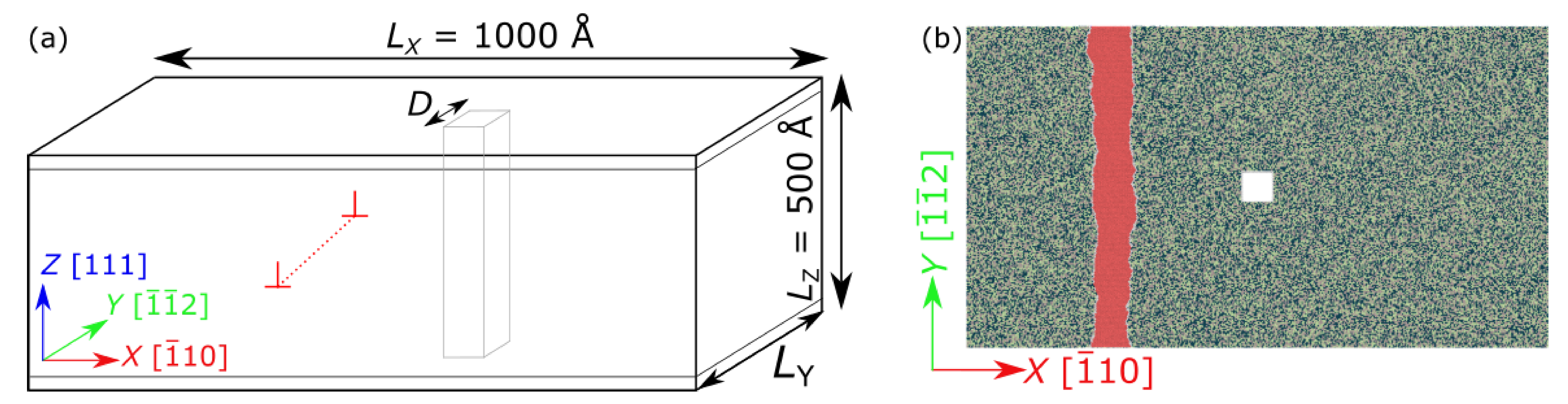
A typical simulation setup used in the current work is shown in Figure 1. To create an equiatomic FeNiCr sample, equal amounts of Fe, Ni, and Cr atoms were randomly placed on the sites of an fcc lattice. The crystallographic orientation of the lattice was chosen such that the (111) plane normal is parallel to the Z axis, the (average) line direction to the Y axis, and the dislocation Burgers vector points in X direction. Simulation boxes of different sizes were used, with standard box dimensions of approximately Å, where Å.
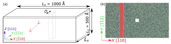
Figure 1.
(a) A typical simulation setup and (b) top view of the dislocation glide plane. An edge dislocation and a square void with side length Å can be seen here. The simulation box is periodic along the X and Y axes. The atoms in the upper and lower boundary layers are free to move only parallel to the plane. The periodicity length , which also defines the periodic void spacing, S, is a simulation parameter. The crystallographic axes are as shown in the individual sub-figures. Color coding: Fe-dark blue, Ni-green, Cr-brown, atoms in dislocation stacking fault–red.
Edge dislocations with Burgers vector , where is the lattice constant of FeNiCr at 0 , were introduced using displacement fields following the method detailed by Rodney [30]. The method allows the creation of partial dislocations with a desired initial splitting distance, which was set to be Å, while also ensuring periodicity along the direction of dislocation motion, i.e., X direction. Invariance of the displacement field in the Y direction ensures periodicity in this direction. Once the dislocation was introduced, a columnar void of a square cross-section and with edge length Å was created parallel to the Z axis by removing atoms in the matrix, as seen in Figure 1. The center of the void is placed 250 Å away from the center of the edge dislocation to avoid a strong interaction between the two before the onset of dislocation glide. We note that changes in void shape do not strongly impact the results, e.g., a cylindrical void whose diameter is the same as the side length of the square void has almost the same CRSS.
Periodic boundary conditions (PBCs) were used along the dislocation line direction and along the direction of dislocation motion, i.e., along the X and Y axis. This setup therefore corresponds to an infinite dislocation interacting with an array of voids of periodicity . The distance between voids, i.e., the inter-void spacing, is denoted by S, where . , and consequently S are simulation parameters in the present work: by changing the periodicity length, one effectively changes the void spacing, since there is only one void in the system. This allows an investigation into the influence of void spacing on the stresses required to overcome voids as obstacles, which is a main purpose of this study. Atoms in the top and bottom layers are constrained to move only in the plane, so their Z position is fixed.
The color coding of these atoms is as follows: Fe—dark blue, Ni—green, Cr—brown, atoms in dislocation stacking fault—red, as described in Figure 1. This initial setup was then relaxed using an optimized version of the FIRE algorithm [31] to reach mechanical equilibrium. In all static and quasistatic simulations in this study, a simulation setup was considered to be energy minimized when the force norm, i.e., the norm of the 3N dimensional force vector, for each atom fell below a threshold value of .
To study dislocations under an externally applied shear stress, forces corresponding to this desired resolved shear stress were applied to the top- and bottom-most atomic layers parallel to the glide plane. The simulation box was then relaxed again until an energy minimized state was found at the given stress. This setup was then used for the next relaxation step at a higher stress. The shear stress was increased until the dislocation moved across the simulation box and overcame the void. The externally applied shear stress is , and, in the following, is denoted by .
The lower bound of the critical resolved shear stress (CRSS) was defined as the highest applied shear stress at which the dislocation remained stuck at the obstacle, while the upper bound was provided by the lowest applied shear stress that resulted in the dislocation moving past the obstacle without reaching another metastable configuration. We evaluate the CRSS as the average of these two values and the CRSS error as the difference between them.
In addition to the outlined sequential quasistatic relaxation scheme, dislocation–void interactions were also studied using molecular dynamics (MD) simulations using the NVE ensemble with an initial temperature of K. The time step for all MD simulations was set to fs.
The Open Visualization Tool (OVITO) [32] was used to visualize and analyze the atomistic configurations. Partial dislocation cores and the stacking faults were identified using adaptive common neighbor analysis (a-CNA) [33,34] as implemented in OVITO.
To identify the respective effects of solute–dislocation interactions and void–dislocation interactions, a previously published study [25] of dislocation–solute interactions in void-free FeNiCr was used as a reference for comparison with the present investigation of FeNiCr with voids.
3. Results and Discussion
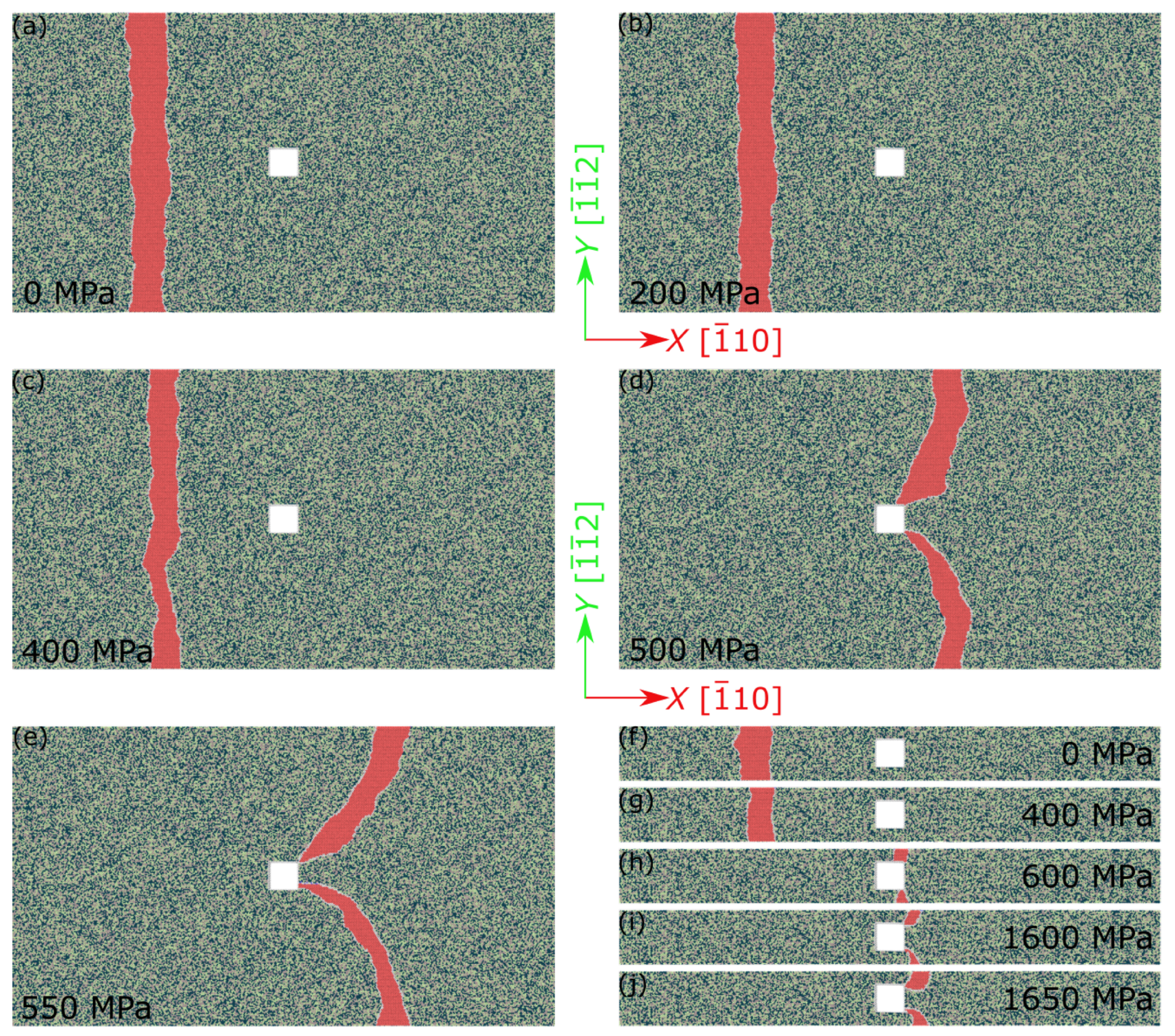
Figure 2 shows the energy minimized states of the edge dislocation at varying but increasing externally applied shear stress for the simulation setup with 550 Å in Figure 2a–e and 100 Å in Figure 2f–j. Let us focus on the simulation setup with 550 Å initially. Upon energy minimization from the initial setup, the initially straight dislocations find a local energy minimum by adjusting to the local, random energy landscape arising from the disordered arrangement of the three types of alloy atoms. As seen from the dislocation structures in Figure 1b and Figure 2a, this results in an irregular shape of the partial dislocation lines.
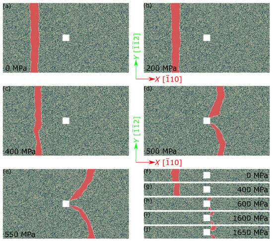
Figure 2.
Energy-minimized states of an infinite edge dislocation with a periodic array of voids under externally applied shear stress , as simulated using quasistatic simulation. See Figure 1 for the color coding of atoms. The simulation box size is approximately (a–e) Å and (f–j) Å. The square void has a side length of 50 Å.
External shear stress is required to move the dislocation from this pinned position. At low shear stress, only parts of the partial dislocations respond to the externally applied stress by finding new local energy minima. This can be seen by comparing Figure 2a,b where the external shear stress increases from 0 MPa to 200 MPa, while the dislocation remains pinned on average. The complex picture of the pinning of extended dislocations, i.e., their ability to adjust the stacking fault width between the weakly coupled partial dislocations to explore a multitude of local energy minima, can be seen here. The same behavior has been previously demonstrated in other studies [5,9,25]. When a higher shear stress is applied, the dislocation is partly displaced and moves onto the glide plane until it reaches a new metastable configuration. Note that the dislocation splitting width is not a constant in Figure 2a–c, but changes as the dislocation adjusts to the local energy landscape.
We note that the metastable energy minima in which the dislocation is pinned before it reaches the void represent frustrated configurations whose energy is well above the global energy minimum configuration. This global energy minimum corresponds to a dislocation which is threading the void, and thus reduces its energy because the line energy of the threading piece disappears (as can be seen in, e.g., [18,35]). Only once the shear stress reaches the critical resolved shear stress of the void-free alloy, which for the present alloy is about 480 MPa [25], the frustrated configurations are eliminated and the dislocation moves forward until it intersects the void and thus gets pinned in a new configuration of reduced energy, Figure 2d.
Further deformation is controlled by the bowing-out of the dislocation from the void which acts as an anchoring volume. At 550 MPa, the dislocation reaches the lower bound of the CRSS, i.e., the highest shear stress where the dislocation remains stuck at the obstacle. Upon applying a higher shear stress of 600 MPa, no stable configurations could be found. The qualitative picture of the dislocation–obstacle interaction described above is consistently found in all simulations that were performed in the present study, and can be seen for 100 Å in Figure 2f–j.
For pure edge or screw dislocations, both types of partial dislocations exhibit identical characteristics (30-degree dislocations for screw types and 60-degree ones for edge types). Consequently, they also have the same resistance to movement, known as pinning stress. However, this uniformity in pinning stress found in pure edge or screw dislocations does not apply to mixed dislocations of a more general orientation, i.e., the pinning stresses for different partial dislocations may not be the same. As a result, the partial dislocation with the lesser pinning stress may begin to move under a lower level of applied stress, leading to a change in stacking fault width. The dislocation keeps moving until the width of the stacking fault changes enough to balance the stresses on each partial dislocation. This makes them match their own pinning stresses, allowing the dislocation to move coherently as a unit.
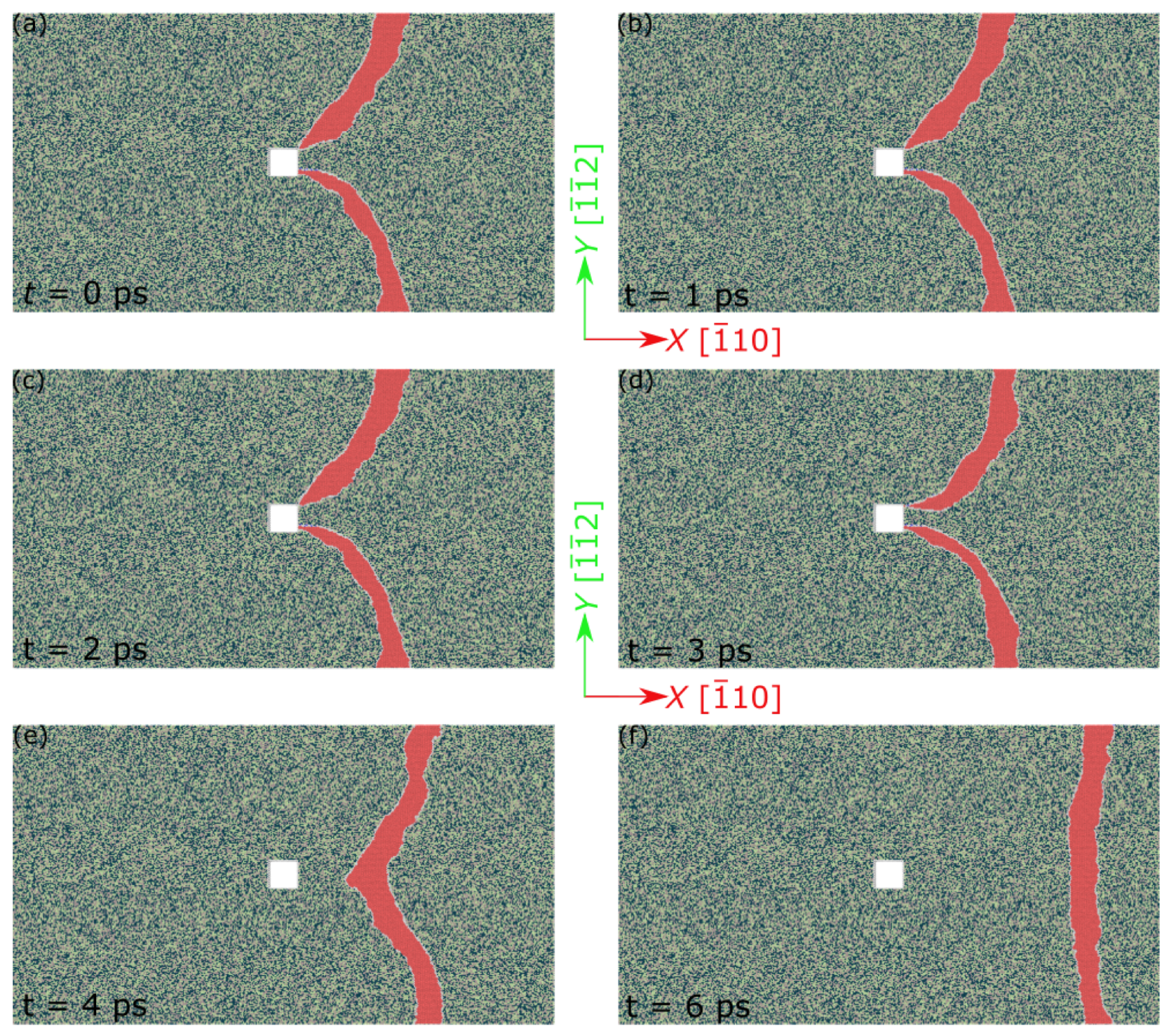
To investigate the mechanism whereby the dislocation detaches from the void, MD simulations were performed using the NVE ensemble ( 0 ). Results are shown in Figure 3 for 550 Å. The relaxed configuration in Figure 2e, i.e., the relaxed configuration at the lower bound CRSS, was used as the starting configuration for the MD simulations. At the onset of the simulation, the stress applied to the top and bottom layers of the simulation box was set to the upper CRSS bound (here 600 MPa for 550 Å) and then kept fixed. During an initial transient of 2 , which is needed for the stress wave caused by the load step to reach the dislocation, the dislocation remains stationary, Figure 3a–c. At 3 , the dislocation arms are moving towards each other and first the leading then the trailing partials annihilate. In the next snapshot at 4 , the dislocation detached from the void, Figure 3d,e. In Figure 3f, the dislocation, no longer pinned by the void, can be seen to move freely across the FeNiCr matrix. The mechanism by which the dislocation detaches from the void is reminiscent of an Orowan process, with partial dislocation arms annihilating each other to overcome the obstacle [36,37], even though the left-behind debris correspond to a void surface step rather than an Orowan loop. Literature studies of dislocation–void interactions in Cu indicate that, at low temperatures (below 300 K in Cu), the depinning mechanisms are similar for edge and screw dislocations [38] whereas at an elevated temperature, the detachment of screw dislocations may involve cross slip processes.
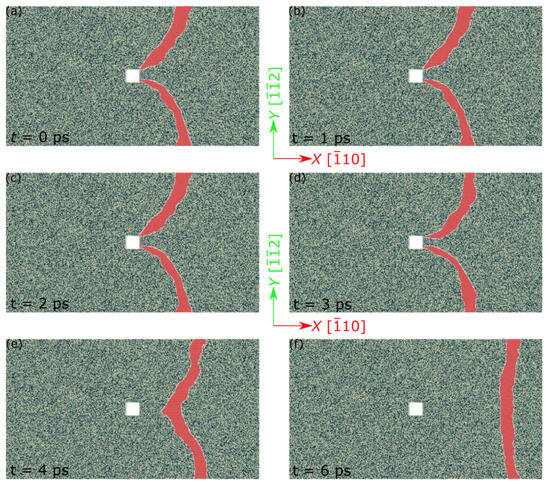
Figure 3.
Snapshots of a time sequence showing an infinite edge dislocation overcoming an array of voids, as simulated by molecular dynamics (NVE at K, MPa); the initial configuration (a) corresponds to Figure 2e. See Figure 1 for color coding. The simulation box size is Å. The square void has a side length of 50 Å.
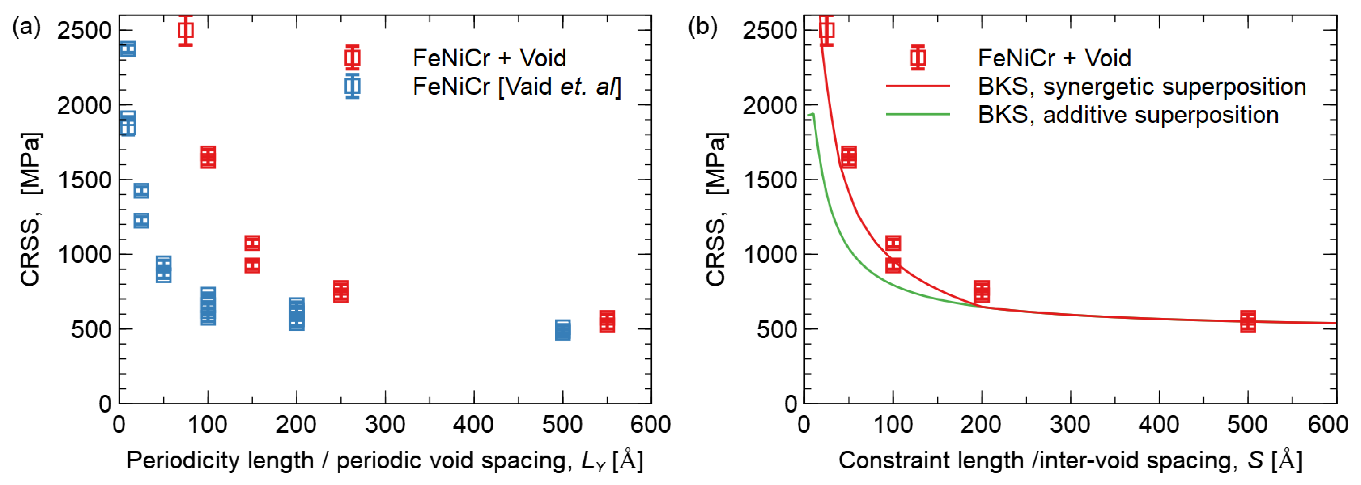
The CRSS required to overcome obstacles depends on the obstacle spacing which, in our simulations, is given by the periodicity length . Figure 4 shows the influence of on the CRSS required to overcome the periodic array of voids. The results are compared to atomistic simulations previously performed by Vaid et al. [25] for systems without voids. Interestingly, even in the absence of voids, the constraint defined by the periodicity length leads to enhanced strength for small . The theoretical reasons for this behavior were explained by Vaid et al. [25]. Adding another obstacle, such as a void, can be seen to further significantly increase the CRSS for dislocation motion. This enhancement becomes more pronounced as the constraint length (the void spacing) decreases.
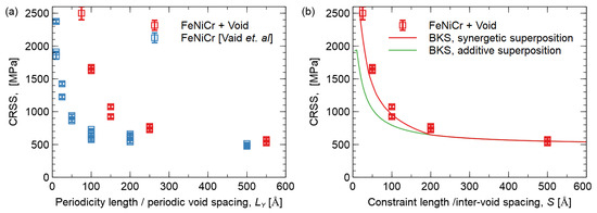
Figure 4.
The critical resolved shear stress (CRSS) needed to overcome obstacles is shown as a function of the periodic void spacing. The first graph (a) displays the CRSS values from this study and compares them to reference values without a void from Vaid et al. (2022) [25]. The second graph (b) shows the data fitted using the BKS equation, with the green curve using an additive superposition, i.e., best-fit constant C value, while the red curve uses a synergistic superposition of C from Vaid et al. (2022) [25].
Given the Orowan-like mechanism for the edge dislocation to overcome the void, we applied the BKS equation as derived by Bacon, Kocks and Scattergood [37] to our data:
Here, is the critical resolved shear stress to overcome an array of obstacles of diameter D and inter-obstacle spacing S; is the effective shear modulus; b is the Burgers vector; and is the harmonic mean of S and D, i.e., ; and C is a constant offset. We identify nm with the void size and evaluate S as . The effective shear modulus, which in the BKS theory depends on dislocation orientation, was evaluated from the cubic elastic constants of the material given in Table A1 (Appendix A) as GPa, using relations derived by Foreman [39].
Using the above values while fitting C to the data gives us the green curve in Figure 4b, where MPa matches well the flow stress caused by solute hardening in void-free bulk FeNiCr as determined by Vaid et al. [25]. At small constraint lengths, however, this curve systematically falls below the simulation data.
Instead of assuming a constant value of C, it may be more appropriate to account for the fact that the strength of solute hardening in CSA, which here is the physical origin of the ‘friction stress’ described by C, depends on the length over which the dislocation adjusts its shape to the atomic energy landscape. For an unconstrained dislocation, this length (‘pinning length’) can be self-consistently evaluated from the elastic properties of the material and the magnitude and correlations of the atomic-scale energy fluctuations [40,41,42]. If, instead, external constraints impose an adjustment length , this leads to enhanced pinning and an increased flow stress as shown by Vaid et al. [25] in simulations, where the constraint length was simply the periodicity length of the simulation box, and by theoretical arguments. Setting the constraint length equal to the inter-void spacing S, and using this length to compute a length-dependent solute pinning stress using the theoretical relations derived by Vaid et al. (see Equations (26) and (27) in their study [25]), we arrive at a modified BKS equation:
This equation can accurately reproduce the data for combined void and solute hardening, without invoking additional fit parameters, as shown by the red curve in Figure 4.
Dou et al. [9] have also studied the interactions of an edge dislocation with a void in FeNiCr-concentrated solid solution alloy, albeit without varying the periodicity length along the dislocation line. They observed a two-stage process with the leading partial dislocation first detaching from the void, followed by the detachment of the trailing partial without discernable annihilation. A possible reason for the differences in the observed mechanism between the two studies relates to the fact that, in their study, the void size was a factor of about 4 smaller than the stacking fault width between the partial dislocations of the edge dislocation after energy minimization in the initial setup. In the present work, on the other hand, the ratio is close to 1.
Qi et al. [10] studied tensile deformation in single-crystal CoCrFeMnNi HEA containing voids of different sizes but no initial dislocations. As typical for this kind of simulation, the stress–strain curves are dominated by a giant yield drop due to the high stress needed for dislocation nucleation, whereas the presence or absence of voids is nearly irrelevant for the deformation behavior. This type of simulation set-up is unsuitable for determining the influence of voids on the flow stress of bulk samples with typical dislocation densities, and we therefore refrain from a detailed comparison.
4. Conclusions
In this paper, we studied the interaction of an edge dislocation with a periodic array of voids in the equiatomic FeNiCr CSA using atomistic simulations. We found the strengthening contributions of solute hardening and obstacle hardening to be additive, i.e., . However, a naive estimate of as the stress needed to move a dislocation in the bulk CSA without voids badly represents the simulation data. Instead, the solute hardening contribution is enhanced by the constraint imposed on the dislocation shape fluctuations in the solute field by the presence of the voids. The latter act as strong anchoring points and their spacing S replaces the pinning length of the void-free bulk material when . This condition defines a regime of synergetic pinning, where the solute action is enhanced by the presence of voids. Accordingly, , while remaining additive to the Orowan stress needed to overcome the voids, itself becomes dependent on the void spacing S. Our model builds upon a generic theory of solute pinning which is not material or composition-specific and for which our results for the void-free case are in excellent agreement with the theoretical predictions [25]. This gives us confidence that our findings may carry over to a wide range of CSAs where the synergetic superposition of void and solute pinning might be relevant.
Our findings could help improve the modeling and design of CSAs with enhanced mechanical properties. For future work, we suggest performing more simulations with different CSA compositions, temperatures, void shapes, dislocation character, etc. to validate and generalize our findings using experimental tests or multiscale simulations. In particular, the case of CSA with the bcc lattice structure may be of interest because there, the easy cross slip of screw dislocations may lead to different depinning scenarios. Also, the observed synergetic hardening mechanism where geometrical constraints enhance the pinning action of solutes may also apply to the superposition of precipitate and solute hardening in CSAs and other materials where precipitate spacings are on the nanometer scale—for instance, in the case of dislocation motion in narrow slip channels consisting of a solute hardened matrix material and confined by stronger precipitates, as typical of superalloy microstructures.
Author Contributions
Conceptualization, A.V., M.Z. and E.B.; methodology, A.V. and E.B.; software, A.V.; validation, A.V., M.Z. and E.B.; data analysis, A.V. and M.Z.; resources, E.B.; data curation, A.V.; writing—original draft preparation, A.V.; writing—review and editing, A.V., M.Z. and E.B.; visualization, A.V.; supervision, E.B.; project administration, E.B.; funding acquisition, M.Z. and E.B. All authors have read and agreed to the published version of the manuscript.
Funding
This research was partly funded by DFG grants number Za 171/8-1 and Bi-1453/2-1. E.B. further acknowledges funding through project C3 of the DFG’s collaborative research center SFB/TR103. All authors acknowledge financial support by Deutsche Forschungsgemeinschaft and Friedrich-Alexander-Universität Erlangen-Nürnberg within the funding programme “Open Access Publication Funding”.
Data Availability Statement
Data presented in this study are openly available on Zenodo, https://doi.org/10.5281/zenodo.8379783.
Conflicts of Interest
The authors declare no conflict of interest. The funders had no role in the design of the study; in the collection, analyses, or interpretation of data; in the writing of the manuscript, or in the decision to publish the results.
Appendix A
A cubic sample (≈ Å), with [100], [010], [001] was used to find the bulk properties, such as the lattice parameter, , and elastic constants, . The sample was relaxed using an optimized implementation of the FIRE algorithm [31] under periodic boundary conditions along all crystallographic axes, and the simulation box size was adjusted. The average stacking fault energy was found using another cuboidal setup (≈ Å) with [112], [1 ], and [1 ] axes, by relaxing only along [1 ], and keeping the atoms fixed along the other directions. The bulk properties are shown in Table A1.

Table A1.
Material parameters for FeNiCr at 0 K.
Table A1.
Material parameters for FeNiCr at 0 K.
| Parameter | Value |
|---|---|
| Lattice parameter, (Å) | 3.52 |
| (GPa) | 242.9 |
| (GPa) | 157.1 |
| (GPa) | 135.0 |
| (Average) stacking fault energy () | 60.5 |
References
- George, E.P.; Raabe, D.; Ritchie, R.O. High-entropy alloys. Nat. Rev. Mater. 2019, 4, 515–534. [Google Scholar] [CrossRef]
- Wang, X.; Mercier, D.; Danard, Y.; Rieger, T.; Perriere, L.; Laurent-Brocq, M.; Guillot, I.; Maurice, V.; Marcus, P. Enhanced passivity of Cr-Fe-Co-Ni-Mo multi-component single-phase face-centred cubic alloys: Design, production and corrosion behaviour. Corros. Sci. 2022, 200, 110233. [Google Scholar] [CrossRef]
- George, E.P.; Curtin, W.A.; Tasan, C.C. High entropy alloys: A focused review of mechanical properties and deformation mechanisms. Acta Mater. 2020, 188, 435–474. [Google Scholar] [CrossRef]
- Saha, J.; Saha, R.; Bhattacharjee, P.P. Microstructure and texture of severely warm-rolled and annealed coarse-grained CoCrNi medium entropy alloy (MEA): A perspective on the initial grain size effect. J. Alloys Compd. 2022, 904, 163954. [Google Scholar] [CrossRef]
- Ma, E. Unusual dislocation behavior in high-entropy alloys. Scr. Mater. 2020, 181, 127–133. [Google Scholar] [CrossRef]
- Basu, I.; Hosson, J.T.M.D. Strengthening mechanisms in high entropy alloys: Fundamental issues. Scr. Mater. 2020, 187, 148–156. [Google Scholar] [CrossRef]
- Inui, H.; Kishida, K.; Chen, Z. Recent Progress in Our Understanding of Phase Stability, Atomic Structures and Mechanical and Functional Properties of High-Entropy Alloys. Mater. Trans. 2022, 63, 394–401. [Google Scholar] [CrossRef]
- Gali, A.; George, E.P. Tensile properties of high- and medium-entropy alloys. Intermetallics 2013, 39, 74–78. [Google Scholar] [CrossRef]
- Dou, Y.K.; Cao, H.; He, X.F.; Gao, J.; Cao, J.L.; Yang, W. Interaction mechanism of an edge dislocation with a void in Fe-Ni-Cr concentrated solid-solution alloy. J. Alloys Compd. 2021, 857, 157556. [Google Scholar] [CrossRef]
- Qi, Y.; Chen, X.; Feng, M. Molecular dynamics-based analysis of the effect of voids and HCP-Phase inclusion on deformation of single-crystal CoCrFeMnNi high-entropy alloy. Mater. Sci. Eng. A 2020, 791, 139444. [Google Scholar] [CrossRef]
- Cawthorne, C.; Fulton, E.J. Voids in irradiated stainless steel. Nature 1967, 216, 5115. [Google Scholar] [CrossRef]
- Polfus, J.M.; Løvvik, O.M.; Bredesen, R.; Peters, T. Hydrogen induced vacancy clustering and void formation mechanisms at grain boundaries in palladium. Acta Mater. 2020, 195, 708–719. [Google Scholar] [CrossRef]
- Fan, Z.; Zhong, W.; Zhong, W.; Jin, K.; Ritchie, R.O.; Bei, H.; Osetsky, Y.; Osetsky, Y.N.; Zhang, Y. Diffusion-mediated chemical concentration variation and void evolution in ion-irradiated NiCoFeCr high-entropy alloy. J. Mater. Res. 2020, 36, 298–310. [Google Scholar] [CrossRef]
- Sui, H.; Yu, L.; Liu, W.; Liu, Y.; Cheng, Y.; Duan, H. Theoretical models of void nucleation and growth for ductile metals under dynamic loading: A review. Matter Radiat. Extrem. 2022, 7, 1. [Google Scholar] [CrossRef]
- Hull, D.; Bacon, D.J. Introduction to Dislocations; Butterworth-Heinemann: Oxford, UK, 2001. [Google Scholar]
- Haghighat, S.M.H.; Fivel, M.C.; Fikar, J.; Schaeublin, R. Dislocation-void interaction in Fe: A comparison between molecular dynamics and dislocation dynamics. J. Nucl. Mater. 2009, 386–388, 102–105. [Google Scholar] [CrossRef]
- Ganeyev, G.Z.; Turkebaev, T.E. The dislocation void interaction. Acta Metall. 1988, 36, 2. [Google Scholar] [CrossRef]
- Bitzek, E.; Gumbsch, P. Dynamic aspects of dislocation motion: Atomistic simulations. Mater. Sci. Eng. A 2005, 400–401, 40–44. [Google Scholar] [CrossRef]
- Jian, W.R.; Zhang, M.; Xu, S.; Beyerlein, I.J. Atomistic simulations of dynamics of an edge dislocation and its interaction with a void in copper: A comparative study. Model. Simul. Mat. Sci. Eng. 2020, 28, 4. [Google Scholar] [CrossRef]
- Cheng, Y.; Bitzek, E.; Weygand, D.; Gumbsch, P. Atomistic simulation of dislocation-void interactions under cyclic loading. Model. Simul. Mat. Sci. Eng. 2010, 18, 2. [Google Scholar] [CrossRef]
- Bacon, D.J.; Osetsky, Y.N.; Rodney, D. Chapter 88 dislocation–obstacle interactions at the atomic level. In Dislocations in Solids; Elsevier: Amsterdam, The Netherlands, 2009; pp. 1–90. [Google Scholar]
- Monnet, G. Mechanical and energetical analysis of molecular dynamics simulations of dislocation–defect interactions. Acta Mater. 2007, 55, 5081–5088. [Google Scholar] [CrossRef]
- Zou, Y. Nanomechanical studies of high-entropy alloys. J. Mater. Res. 2018, 33, 3035–3054. [Google Scholar] [CrossRef]
- Miracle, D.B. High-Entropy Alloys: A Current Evaluation of Founding Ideas and Core Effects and Exploring `Nonlinear Alloys. JOM 2017, 69, 2130–2136. [Google Scholar] [CrossRef]
- Vaid, A.; Wei, D.; Bitzek, E.; Nasiri, S.; Zaiser, M. Pinning of extended dislocations in atomically disordered crystals. Acta Mater. 2022, 236, 118095. [Google Scholar] [CrossRef]
- Plimpton, S. Fast Parallel Algorithms for Short-Range Molecular Dynamics. J. Comput. Phys. 1995, 117, 1–19. [Google Scholar] [CrossRef]
- Bonny, G.; Terentyev, D.; Pasianot, R.C.; Poncé, S.; Bakaev, A. Interatomic potential to study plasticity in stainless steels: The FeNiCr model alloy. Model. Simul. Mat. Sci. Eng. 2011, 19, 8. [Google Scholar] [CrossRef]
- Osetsky, Y.N.; Pharr, G.M.; Morris, J.R. Two modes of screw dislocation glide in fcc single-phase concentrated alloys. Acta Mater. 2019, 164, 741–748. [Google Scholar] [CrossRef]
- Varvenne, C.; Luque, A.; Curtin, W.A. Theory of strengthening in fcc high entropy alloys. Acta Mater. 2016, 118, 164–176. [Google Scholar] [CrossRef]
- Rodney, D. Molecular dynamics simulation of screw dislocations interacting with interstitial frank loops in a model FCC crystal. Acta Mater. 2004, 52, 3. [Google Scholar] [CrossRef]
- Guénolé, J.; Nöhring, W.G.; Vaid, A.; Houllé, F.; Xie, Z.; Prakash, A.; Bitzek, E. Assessment and optimization of the fast inertial relaxation engine (fire) for energy minimization in atomistic simulations and its implementation in LAMMPS. Comput. Mater. Sci. 2019, 175, 109584. [Google Scholar] [CrossRef]
- Stukowski, A. Visualization and analysis of atomistic simulation data with OVITO-the Open Visualization Tool. Model. Simul. Mat. Sci. Eng. 2010, 18, 15012. [Google Scholar] [CrossRef]
- Faken, D.; Jónsson, H. Systematic analysis of local atomic structure combined with 3D computer graphics. Comput. Mater. Sci. 1994, 2, 279–286. [Google Scholar] [CrossRef]
- Honeycutt, J.D.; Andemen, H.C. Molecular Dynamics Study of Melting and Freezing of Small Lennard- Jones Clusters. J. Phys. Chem. 1987, 91, 4950–4963. [Google Scholar] [CrossRef]
- Nasiri, S.; Zaiser, M. Effects of elasticity and dislocation core structure on the interaction of dislocations with embedded CNTs in aluminium: An atomistic simulation study. Materialia 2022, 21, 101347. [Google Scholar] [CrossRef]
- Scattergood, R.O.; Bacon, D.J. The Orowan mechanism in anisotropic crystals. Philos. Mag. 1975, 31, 179–198. [Google Scholar] [CrossRef]
- Bacon, D.J.; Kocks, U.F.; Scattergood, R.O. The effect of dislocation self-interaction on the orowan stress. Philos. Mag. 1973, 28, 1241–1263. [Google Scholar] [CrossRef]
- Hatano, T.; Kaneko, T.; Abe, Y.; Matsui, H. Void-induced cross slip of screw dislocations in fcc copper. Phys. Rev. B 2008, 77, 064108. [Google Scholar] [CrossRef]
- Foreman, A.J.E. Dislocation energies in anisotropic crystals. Acta Metall. 1955, 3, 4. [Google Scholar] [CrossRef]
- Zapperi, S.; Zaiser, M. Depinning of a dislocation: The influence of long-range interactions. Mater. Sci. Eng. A 2001, 309, 348–351. [Google Scholar] [CrossRef]
- Zaiser, M. Dislocation motion in a random solid solution. Philos. Mag. A 2002, 82, 2869–2883. [Google Scholar] [CrossRef]
- Zaiser, M.; Wu, R. Pinning of dislocations in disordered alloys: Effects of dislocation orientation. Mater. Theory 2022, 6, 4. [Google Scholar] [CrossRef]
Disclaimer/Publisher’s Note: The statements, opinions and data contained in all publications are solely those of the individual author(s) and contributor(s) and not of MDPI and/or the editor(s). MDPI and/or the editor(s) disclaim responsibility for any injury to people or property resulting from any ideas, methods, instructions or products referred to in the content. |
© 2023 by the authors. Licensee MDPI, Basel, Switzerland. This article is an open access article distributed under the terms and conditions of the Creative Commons Attribution (CC BY) license (https://creativecommons.org/licenses/by/4.0/).