Abstract
In the coupled pickling line and tandem cold mill (PL-TCM), the hot-rolled strip needs to be trimmed on both sides of the strip before the tandem cold rolling process to ensure stable operation of the rolling process. The equipment for trimming the strip is the side trimmer, and during trimming a failure of the side scrap blockage is often caused by the variation in the width of the hot-rolled strip and the deviation during the actual operation. For this problem, this paper established a finite element model of strip trimming by side trimmer, analyzed the influence of side scrap width, structure parameters, and strip specifications on the equivalent plastic strain at the trimmed position of the strip, and obtained the influence law of each factor during the trimming process. On this basis, by collecting the historical data of side scrap blockage failure of the side trimmer, the threshold value of the side scrap width setting is obtained. Combining the width data of the hot-rolled strip and the actual operation status monitoring of the strip in the inlet section of the PL-TCM, the side scrap blockage risk identification function and the speed reduction strategy of the side trimmer are designed to form the side scrap blockage pre-control model together. After applying the side scrap blockage pre-control model to a PL-TCM, a 40.5% reduction in side scrap blockage failures was achieved compared with the same length of time before the application, which achieved satisfactory results.
1. Introduction
As an important product line for deep processing of strip, the main equipment of the coupled pickling line and tandem cold mill (PL-TCM) includes pay-off reels, leveler, laser welder, looper, pickling tank, center position control system (CPC), side trimmer, 5-stand tandem cold mill, etc. [1]. The raw material of the PL-TCM is usually the hot-rolled strip, which often has defects such as irregularity and cracks on the sides, so it often needs side trim treatment before rolling [2,3,4]. In the PL-TCM, the hot-rolled strip after shearing, welding, and pickling, in front of the entrance to the tandem cold mill is arranged with a side trimmer equipment, used to trim both sides of the strip according to the required width to provide protection for the stable operation of the tandem cold rolling process [5,6].
The side trimmer is a weak link in the PL-TCM prone to accidents as well as affecting production efficiency, which is a kind of shearing machine, whose blades are two rotating discs, mainly used for the longitudinal trim process of the side of the strip, generally arranged in the strip continuous operation of the production line. In the PL-TCM, the process control system sets different opening sizes for different strip widths and trims the running strip. The scrap produced after the trimming is cut into short scraps of constant length through a shearing device and then dropped into the scrap bin.
For the process of trimming the strip side with the side trimmer, Jinpeng Ji et al. analyzed the additional axial force exerted on the blades by the sickle-shaped bending bend of the strip during trimming for the problem of low trimming accuracy due to the axial instability of disc blades, and the trimming accuracy was significantly improved after increasing the radial locking force [7]. Zhenhua Bai et al. proposed the concept of comprehensive quality of trimming and optimized the tension before and after the trimming process of the side trimmer, which effectively improved the quality of trimming [8]. Kuan Xu et al. introduced the Gissmo material failure criterion and used the finite element method to calculate the effects of the stresses on the upper disc blade under different side trimmer structure parameter settings, and the simulation results have good accuracy [9]. Qunping Jing et al. used ANSYS/LS-DYNA to establish a finite element model of side trimmer for elastic-plastic finite element analysis, and obtained the stress-strain state in the process of strip trimming and verified its reliability [10]. Bing Chen et al. used the finite element method to investigate the section burr phenomenon prevalent in trimming, and explored the relationship between a number of influencing factors [11]. Lifeng Ma et al. carried out research on the problems of poor shear quality and large deviation of shear force theoretical calculation, and established a comprehensive strip thickness, material properties, and cumulative shear area of disc shear blade gap adjustment model, which has achieved certain results [12]. Shengcun Li studied the elements leading to trimming defects and preventive measures, and the passing rate of IF steel trimming was greatly improved by methods such as limiting the clearance and overlap deviation of the tool [13]. Dongfang Li et al. used the elastic-plastic finite element method to establish a numerical model of the trimming process, and calculated and analyzed the shear force and its distribution law under different conditions [14]. Some scholars have also applied the finite element method to study the state of the strip after being sheared. Rasool M et al. investigated the stability characteristics of isotropic and composite shear panels by using the shear deformation finite element method and studied the post-buckling behavior of thin plates [15].
A disc slitting machine is commonly used in the shearing process of the strip, its structure and shearing principle are consistent with the side trimmer, and some scholars have also conducted research on various aspects of it. Yiwei Zhu et al. designed a measurement system for real-time detection of three-direction shear force during disc slitting and developed a fault diagnosis method based on wavelet packet transform and support vector machine, which can effectively identify blade runout and has good application value [16]. Jun Zeng et al. established a wear model of the disc blade based on Archard wear theory after analyzing the contact stress and relative slip velocity of the disc blade edge under different machining parameters [17]. Qiusheng Yan et al. have performed a series of research on disc slitting. In 2012, they analyzed the process of metal strip slitting and proposed to set the upper and lower pairs of disc knives as axial negative clearance and radial positive clearance to achieve less burr-free precision slitting [18]. In 2014, they investigated the effect of the setting of clearance amount on the sectional morphology and obtained the set interval of reasonable clearance amount based on the thickness of the strip [19]. In 2016, they analyzed the deformation process and the formation of cross-section morphology of galvanized sheet through the variation in metal rheological organization and material hydrostatic stress [20]. J Zeng et al. developed a DEFORM-2D model for studying the wear process of disc tools and the slitting quality during disc slitting [21]. Wenya Feng et al. studied the effect of disc slitting side clearance on the shape of the parting-off surface and work hardening, and found that the disc slitting side clearance is a key factor affecting the work hardening of the material, and also has a certain effect on the shape of the parting-off surface [22].
The essence of side trimmer trimming strip is the fracture behavior of the material, for such problems, the finite element method is commonly used as an auxiliary means to research the fracture behavior of various materials [23,24]. With the help of mature finite element software, various scholars have made multi-dimensional studies on the fracture behavior of various types of materials, including ferrous metals, non-ferrous metals, and composites, etc., which have achieved promising results and proved the effectiveness of their methods in such research [25,26].
The research of the above scholars focused on the shearing mechanism of disc slitting and side trimmer and the influence of structural parameters on the shearing process, with less attention to the operational stability of the strip shearing process in the actual production line. In this paper, focusing on the side scrap blockage problem that often occurs in the trimming process of the inlet section of the PL-TCM, we first established the finite element model to analyze the effect of the main structural parameters of the side trimmer, the width of the side scrap, and the strip specification on the equivalent plastic strain at the trimming position of the strip. Secondly, according to the numerical simulation results, combined with the actual production data of industrial sites, the set threshold value of the side scrap width is obtained. Thirdly, based on the quality data of the hot-rolled strip and the operating status monitoring data of the strip at the entrance section of the PL-TCM, the static and dynamic risk identification methods for the risk of side scrap blockage are designed, and the corresponding speed reduction strategies are designed for each risk type. Finally, the side scrap blockage risk identification model and the speed reduction strategy are actually applied to a PL-TCM, and a human machine interface is designed so that operators can pay attention to the strip running and trimming status in real time according to the human machine interface (HMI). After the application of the above functions in the target PL-TCM, the side scrap blockage failure is significantly reduced, and the use of the effect is in line with expectations.
2. Analysis of the Causes of Side Scrap Blockage Risk during Trimming
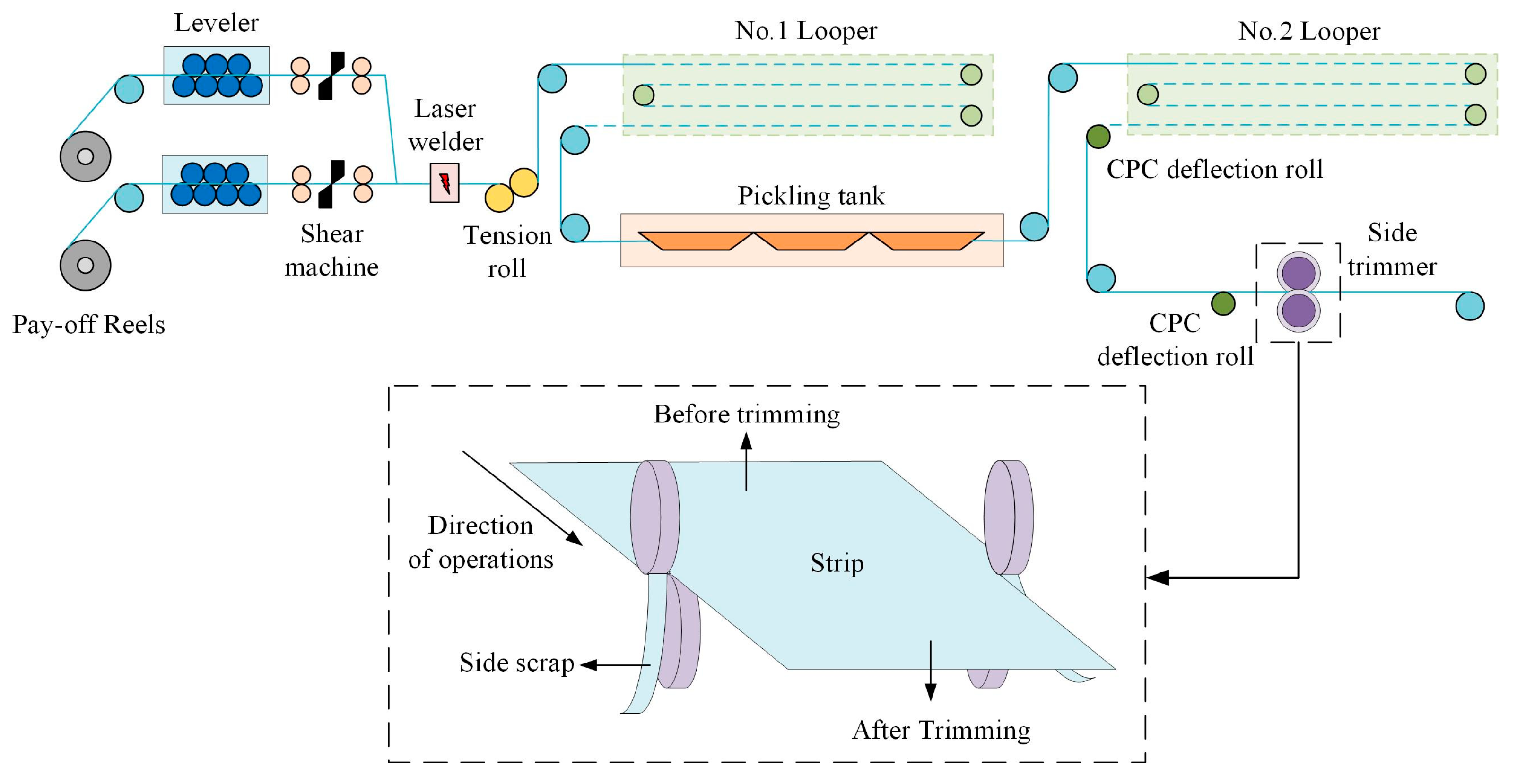
The side trimmer is a type of shearing machine whose blades are two discs arranged up and down and rotating in opposite directions for longitudinal trimming of the strip side during the operation process. As shown in Figure 1, the equipment arrangement of the inlet section of the PL-TCM is illustrated, and the side trimmer is arranged after the pickling process.
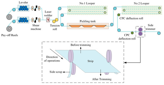
Figure 1.
Equipment arrangement of the inlet section of the PL-TCM.
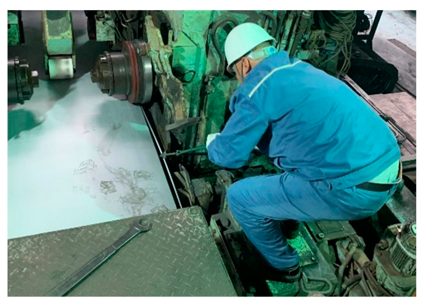
During the trimming process, it is necessary to keep the side scrap width of the strip on both sides as stable as possible, but the strip may deviate in the production line due to the asymmetric shape of the strip, head, and tail sickle-shaped bending, etc. When the strip deviates, the width of the side scrap on both sides of the side trimmer may change, and when the width of the side scrap on either side is too small, there will occur a scrap blockage failure. This requires the operator to manually remove the side scrap from the middle of the two blades of the side trimmer, to confirm that the equipment is normal before turning on the machine. As shown in Figure 2 is a diagram of the manual processing of the blocked side scrap.

Figure 2.
Manual handling of side scrap blockage failure.
According to the industrial site summary, the following are the common causes of side scrap blockage at present:
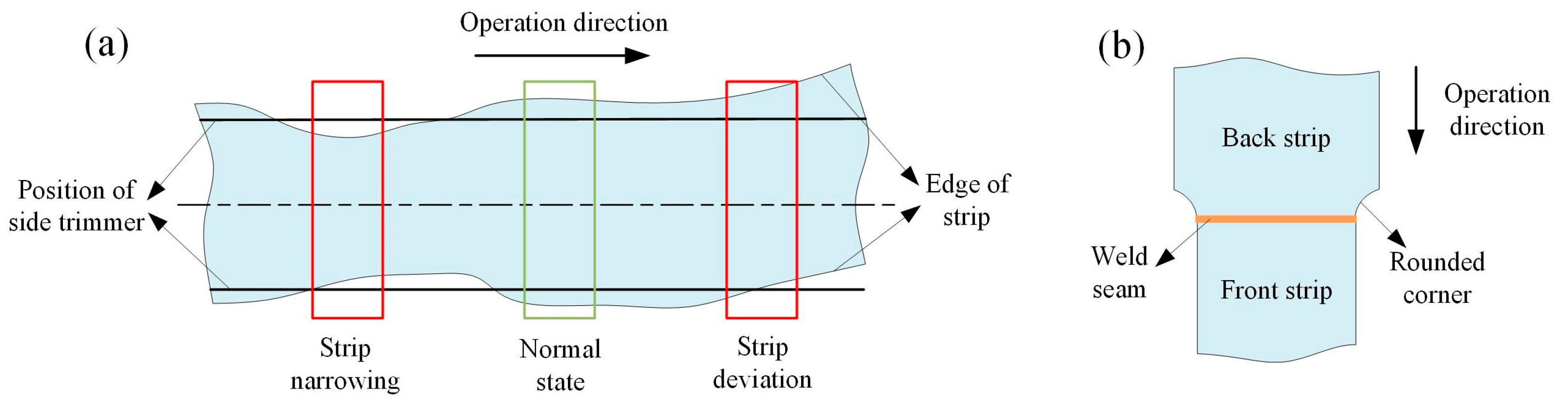
(1) Side scrap blockage caused by strip deviation, as shown in Figure 3a. Due to the influence of asymmetric shape factors, such as strip wedge, single side wave, etc., causing the strip deviation phenomenon when running on the production line, which leads to changes in the width of both sides of the side scrap, the side scrap width of the smaller side of the blockage probability will greatly increase.
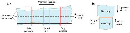
Figure 3.
Schematic shape of the strip, (a) possible forms of blockage risk during strip trimming and (b) strip near weld seam.
(2) Side scrap blockage caused by the narrowing of the strip width, as shown in Figure 3a. In case of narrowing of the strip width at a certain position in the strip length direction or damage at a certain part of the strip side, when this position is run to the side trimmer position, the width of the side scrap on both sides is bound to decrease, and the probability of blockage will be greatly increased at this time.
(3) Side scrap blockage caused by poor scrap fall. After the side scrap is generated by the side trimmer, when the side scrap bending and other reasons caused by the fall are not smooth, there will be a buildup of scrap, which causes the side scrap to block between the blades. Usually after clearing the blocked scrap can be smoothly restored to production.
(4) Side scrap blockage caused by strip change specifications. According to the characteristics of the production plan scheduling of the PL-TCM, the strip width specification changes mostly from the widest to the narrowest, and then from the narrowest directly to the widest rule to arrange. When the front and back strip width specifications are different during the production process, it will stop when the weld seam runs near the side trimmer, cut the weld seam position of the strip out of the rounded shape, and then restart the machine to trim the strip side. A schematic of cutting a round corner at the strip weld seam is shown in Figure 3b. When restarting, the side scrap is prone to blockage, but at this time the operating speed is extremely low and is generally controlled manually by the operator, so the impact is relatively small.
Among the above causes of side scrap blockage in the trimming process of the side trimmer, the essence of the blockage failure during the trimming process caused by strip deviation and narrowing width is the change in the width of the side scrap, and there is currently no effective means of prevention for the PL-TCM. The factors affecting the side scrap trimming process is analyzed later through the finite element method.
3. Finite Element Model of Side Trimmer
3.1. Structure of Side Trimmer
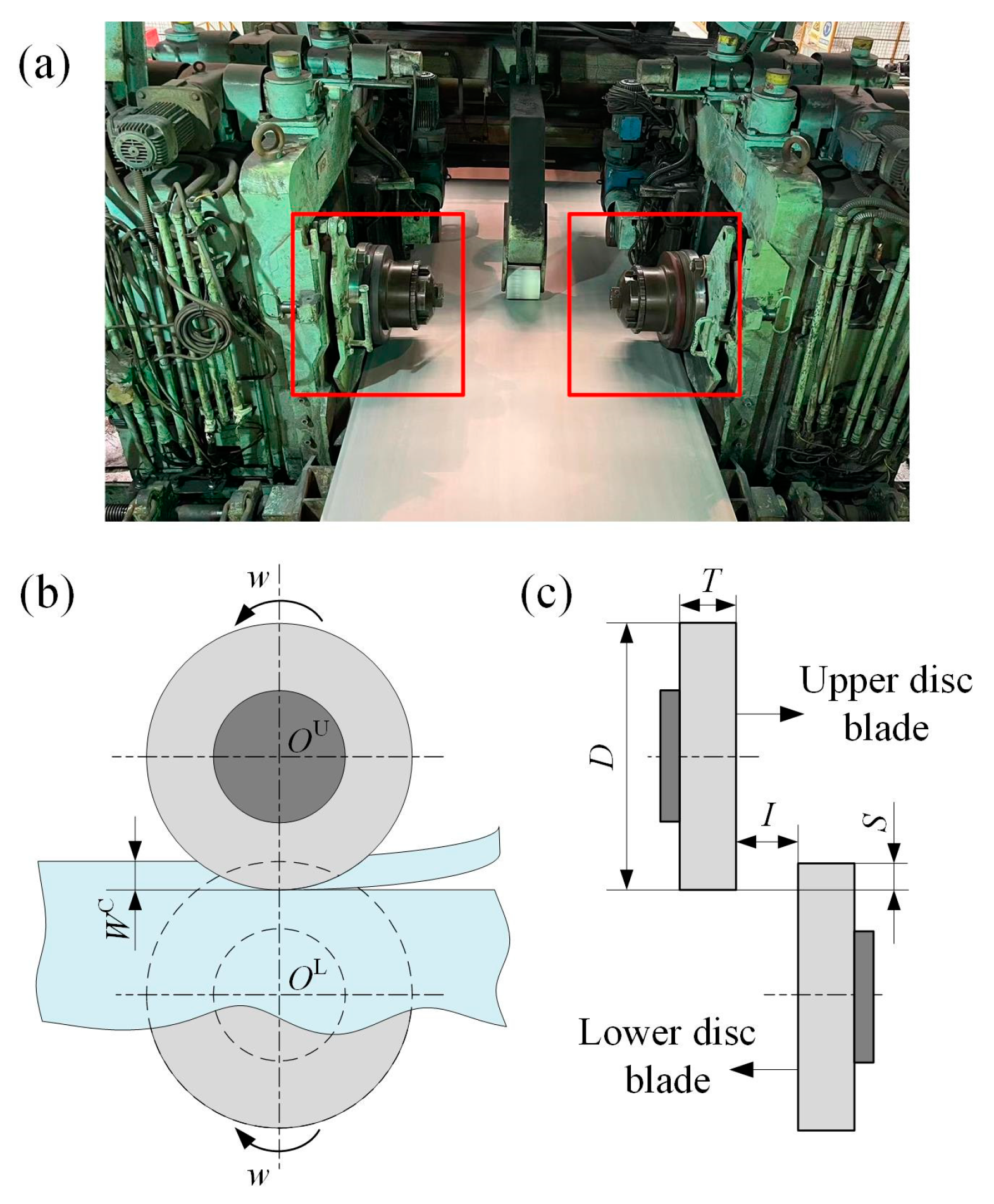
The structure of the side trimmer for the PL-TCM is schematically shown in Figure 4. Its main structural parameters include disc blade size, clearance amount (I), and overlap amount (S). The dimensions of the disc blade include the diameter (D) and thickness (T). The side scrap width (WC) is the setting for the trimming process. To ensure the stable operation of the side trimmer in the PL-TCM, its clearance amount and overlap amount are set in relation to the state of the strip being trimmed, which includes the side scrap width, thickness, and material parameters.
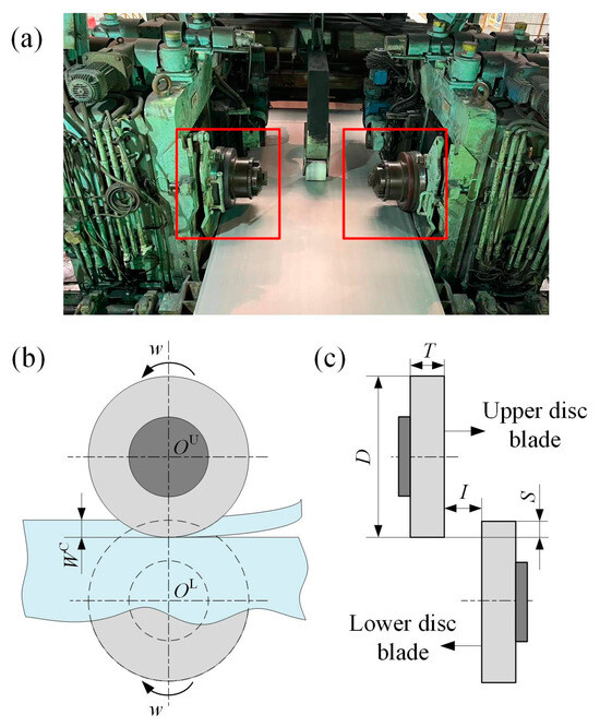
Figure 4.
Structure of side trimmer, (a) arrangement of actual side trimmer, (b) main view and (c) side view of the side trimmer.
3.2. Finite Element Modeling of Side Trimmer
The side trimming process of the side trimmer is a complex nonlinear problem involving contact, friction, and fracture, and the numerical simulation method has a high accuracy for the analysis of such problems [27,28,29]. The ABAQUS, as a mature commercial finite element software, has high accuracy for the analysis of nonlinear problems in the engineering field, so it is chosen as an auxiliary analysis tool for this paper [30,31]. The analysis module of ABAQUS/Explicit was selected according to the characteristics of the trimming process, where the load during the disc blade rotation is dynamic. This module enables effective simulation of linear as well as nonlinear problems with stable velocities and is also very effective in dealing with nonlinear problems with changing contact conditions.
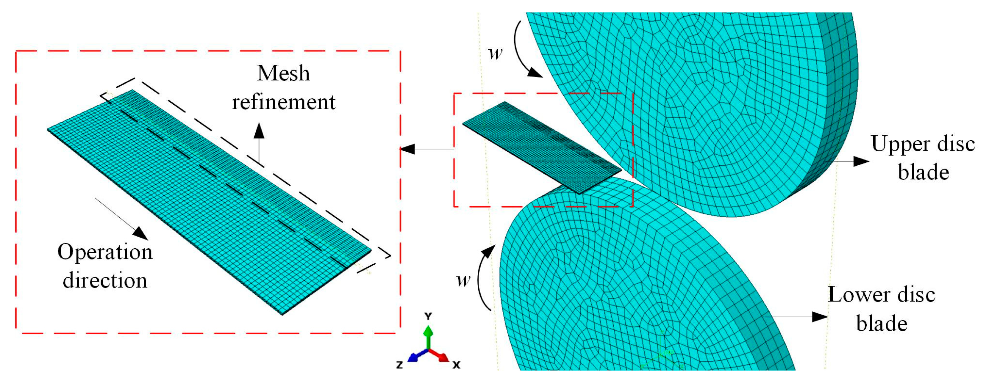
The analysis of the side trimming process focuses on the changes in the side scrap of the strip, in order to facilitate the analysis of the side trimmer structure parameters and strip material parameters on the impact of the trimming process, considering the trimming process as an ideal state, set the upper and lower disc blade as analytical rigid for modeling and cell type is R3D4. As shown in Figure 5 for the geometric model of the side trimmer, the dimensions of the disc blade refer to the actual side trimmer size of the industrial site, the specific dimensions are shown in Table 1. Due to the symmetry between the operating side and the drive side of the strip trimming process, only one side is modeled. Table 1 lists the range of settings for the structural parameters of the side trimmer, and the specific analysis is described in detail in the later sections. The strip is set as a deformable body, and the focus of this analysis is on the trimming position of the strip, so there is no need to model the original dimensions of the strip, and only part of the strip can be created, the specific dimensions are shown in Table 1.
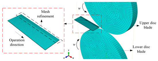
Figure 5.
Geometric model of side trimmer.

Table 1.
Specific dimensions.
According to the trimming process, the elastic, plastic, and fracture properties of the strip material need to be set in the finite element model. This paper chooses to define a ductile fracture criterion and combine it with cell deletion to deal with the shear fracture problem [32,33,34]. Among the many ductile fracture criteria, the Shear Damage criterion is commonly used in shear simulation experiments and has been shown to have high accuracy. The principle is to determine whether a material is fractured or not based on whether the equivalent plastic strain at a certain integral cell of the divided mesh reaches the material fracture [35,36]. The model assumes that the equivalent plastic strain when the material begins to fracture is a function of the shear stress ratio and the strain rate, and the effect of the triaxiality of the stress needs to be considered in the shear stress, which is defined for the shear stress ratio as shown in Equation (1) [37,38,39].
where θS is the shear stress ratio; kS is the stress triaxiality weight factor; η is the stress triaxiality; q is the equivalent mises stress; and τmax is the maximum shear stress.
Define the fracture parameter w. Cell failure can be judged when the fracture parameter reaches 1, as shown in Equation (2).
where w is the fracture parameter; is the initial equivalent plastic strain; is the equivalent strain increment; is the equivalent plastic strain at fracture of the material.
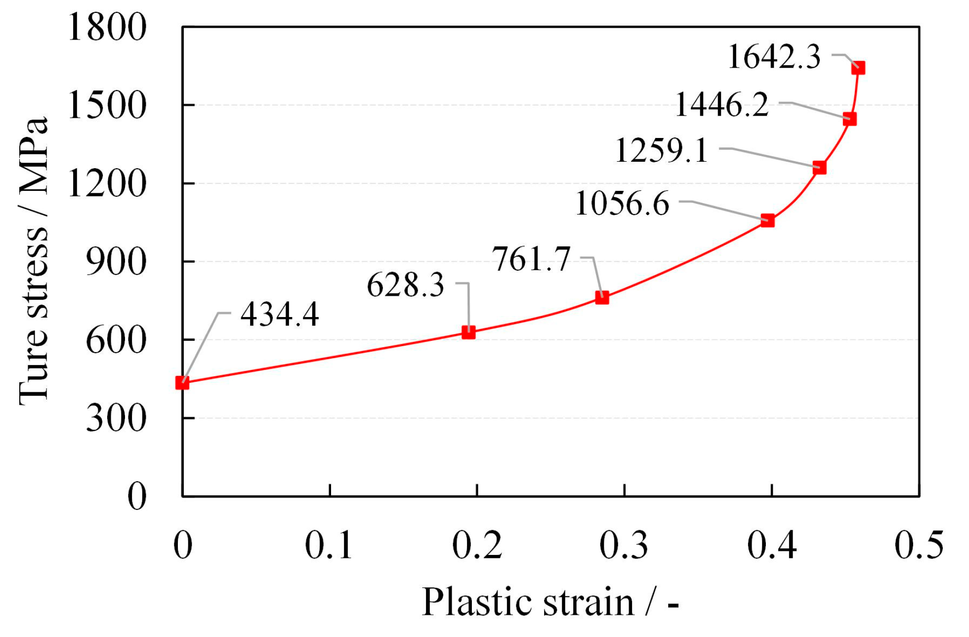
The strip material properties in this paper are described by selecting the relevant parameters of DP600 steel involved in the production of PL-TCM, whose elastic and plastic behavior parameters are shown in Table 2 [40,41]. Convert the engineering stress-strain curves into true stress-strain curves by Equation (3).
where σnom is engineering stress, ɛnom is engineering strain, σtrue is true stress, and ɛtrue is true strain. The true stress-strain curve of the material is shown in Figure 6.
Table 2.
Parameter values.
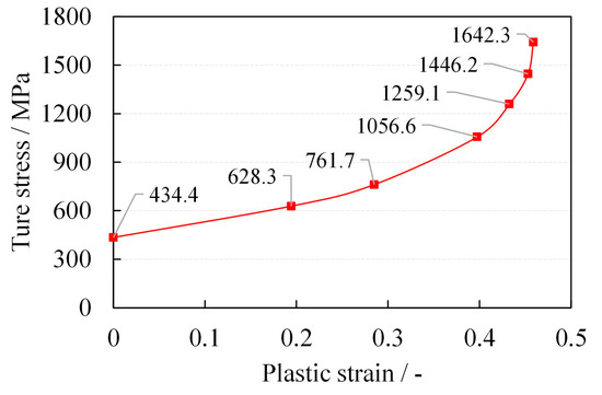
Figure 6.
True stress-strain curve of the material.
The Shear Damage criterion is selected as the criterion for the fracture of the strip trimming process, and the relevant detailed parameter settings are shown in Table 2.
The contact between the disc blade and the strip is selected for the dynamic contact method with more stringent requirements and higher accuracy. The friction model is selected as coulomb friction and the friction coefficient is set to 0.1. To ensure the accuracy of the model calculation, the 8-node linear hexahedral linearly reduced integral cell C3D8R is selected for meshing, and the mesh of the strip trim region is refined, as shown in Figure 5. In the actual trimming process, both sides of the strip are simultaneously sheared by a side trimmer symmetrical about the centerline, and it can be considered that there is no displacement of the strip along the width direction. Therefore, the model constrains the displacement of the strip body side along the width direction, while the trimmed side is set as the free side. Similarly, for the side trimmer, the displacement along the width direction is constrained. Set the upper and lower disk blades to rotate in opposite directions with a rotational speed of 62.8 rad/s; the initial speed of the strip moving in the direction of the blades is 120 m/min to complete the trimming process.
4. Effect of the Influencing Factors on the Trimming Process
As described above in the finite element modeling process, the determination of strip fracture during the trimming process is based on the equivalent plastic strain of the material, so the focus of this paper for the simulation process is on the equivalent plastic strain of the trimming position of the strip side. In the process of trimming the strip by side trimming, the strip first undergoes elastic deformation along the trim section, and with the increase in the degree of trim, the strip in the trim area undergoes plastic deformation. When the equivalent plastic strain at the trimmed position of the strip reaches the standard of the fracture criterion, the side scrap is trimmed off smoothly; if the equivalent plastic strain is small, the side scrap only bending deformation occurs, and then the side scrap blockage phenomenon occurs.
Based on the analysis of the causes of side scrap blockage in the side trimmer in Section 2, this section first analyzes the effect of the side scrap width setting on the equivalent plastic strain during trimming.
4.1. Effect of Side Scrap Width on the Trimming Process of Side Trimmer
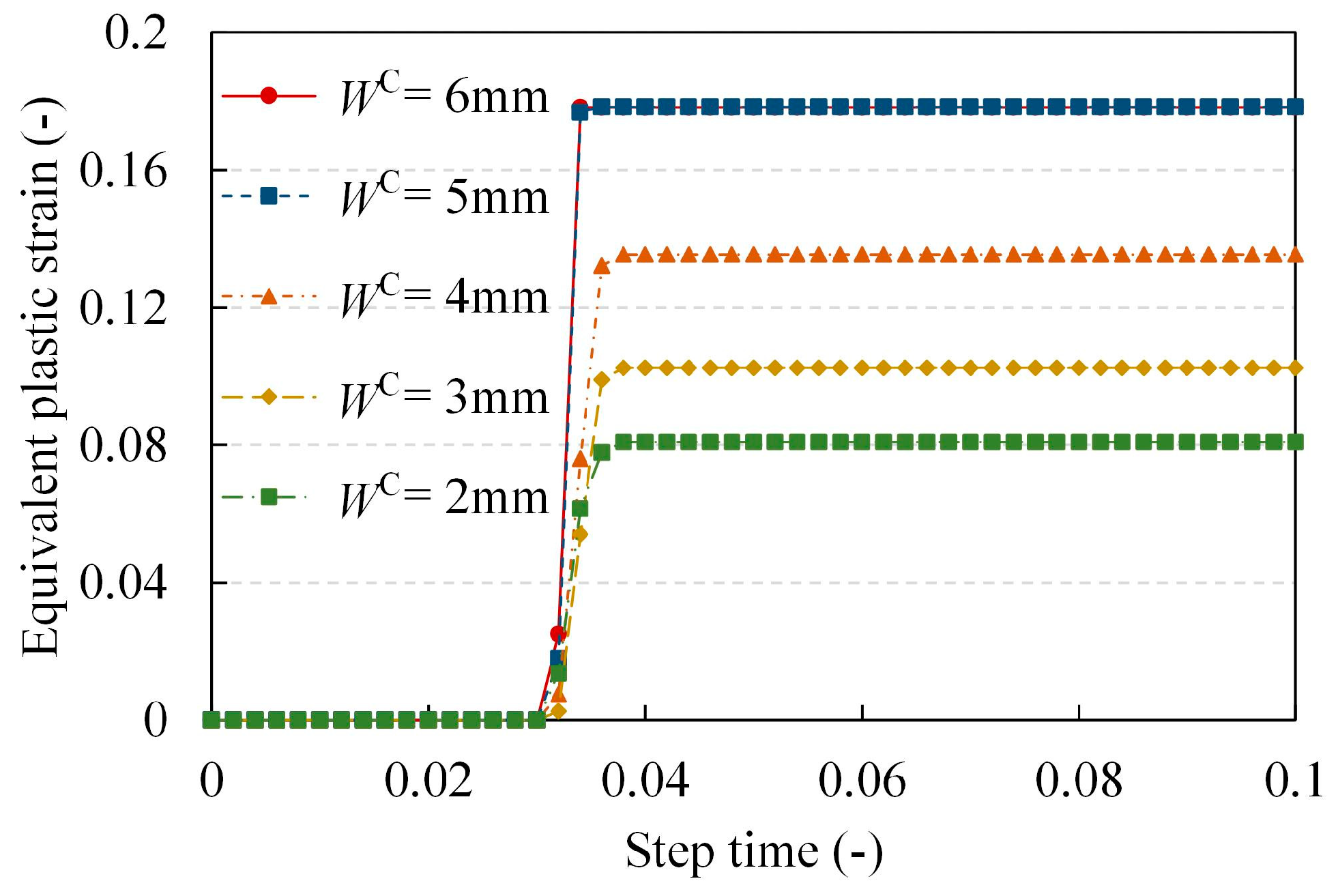
Fixing other parameters (T = 1 mm, S = 0.2 mm, I = 0.3 mm) and adjusting only the side scrap width, Figure 7 shows the equivalent plastic strain clouds of the trim position of the strip with different side scrap width settings. Since the mode of unit deletion is selected to handle the material fracture during the modeling process, the destroyed units are not shown in the cloud diagram. The equivalent plastic strain with time for the strip trim position unit with the side scrap width set in the range of 2~6 mm is extracted as shown in Figure 8. The equivalent plastic strain data were all for cells 40 mm away from the head of the strip in the trimming path, which is due to the consideration of the need to extract the equivalent plastic strains after stabilizing the trimming.
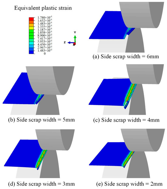
Figure 7.
Equivalent plastic strain clouds of the trimming processes with different side scrap width, (a–e) for the side scrap widths of 6~2 mm.
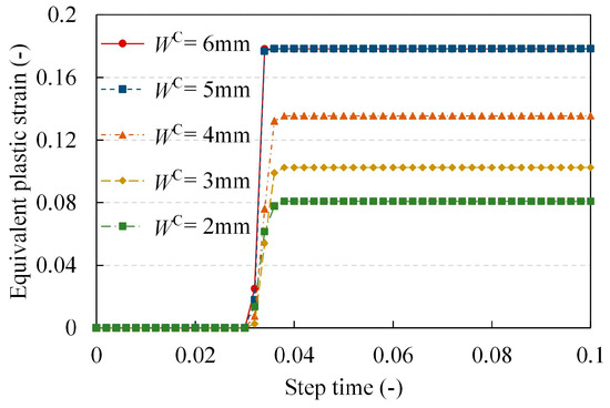
Figure 8.
Equivalent plastic strain curves of the trimming processes with different side scrap width.
It was observed in Figure 7 that the side scrap was trimmed smoothly when the side scrap width was in the range of 5~6 mm. And the equivalent plastic strain in the trim position unit of the strip is 0.178 in the maximum value of the trim process. When the side scrap width is in the range of 2~4 mm, the side scrap is not trimmed smoothly and the equivalent plastic strain of the corresponding unit at the trimmed position of the strip is less than 0.178, and decreases with the decrease in the side scrap width. This shows that the setting of the side scrap width affects the equivalent plastic strain of the strip during the trimming process, and a smaller side scrap width will make the equivalent plastic strain at the trimmed position smaller, and cannot be trimmed smoothly, thus leading to side scrap blockage failure. This corresponds to the analysis of the causes of side scrap blockage failure in the PL-TCM in Section 2.
Since the structural parameter settings of the side trimmer do not change during the actual trimming process, while the side scrap width is a variable due to the fluctuation of the width of the strip and the change in the deviation state during the operation. Therefore, it is necessary to analyze the influence of the structural parameters of the side trimmer on the side scrap trimming process at different side scrap widths.
4.2. Effect of Structural Parameters of Side Trimmer on the Trimming Process
Different work conditions are designed for different side trimmer structural parameters corresponding to different side scrap widths for simulation calculations, where the side trimmer structural parameters include the overlap amount and clearance amount, and the calculation results are compiled.
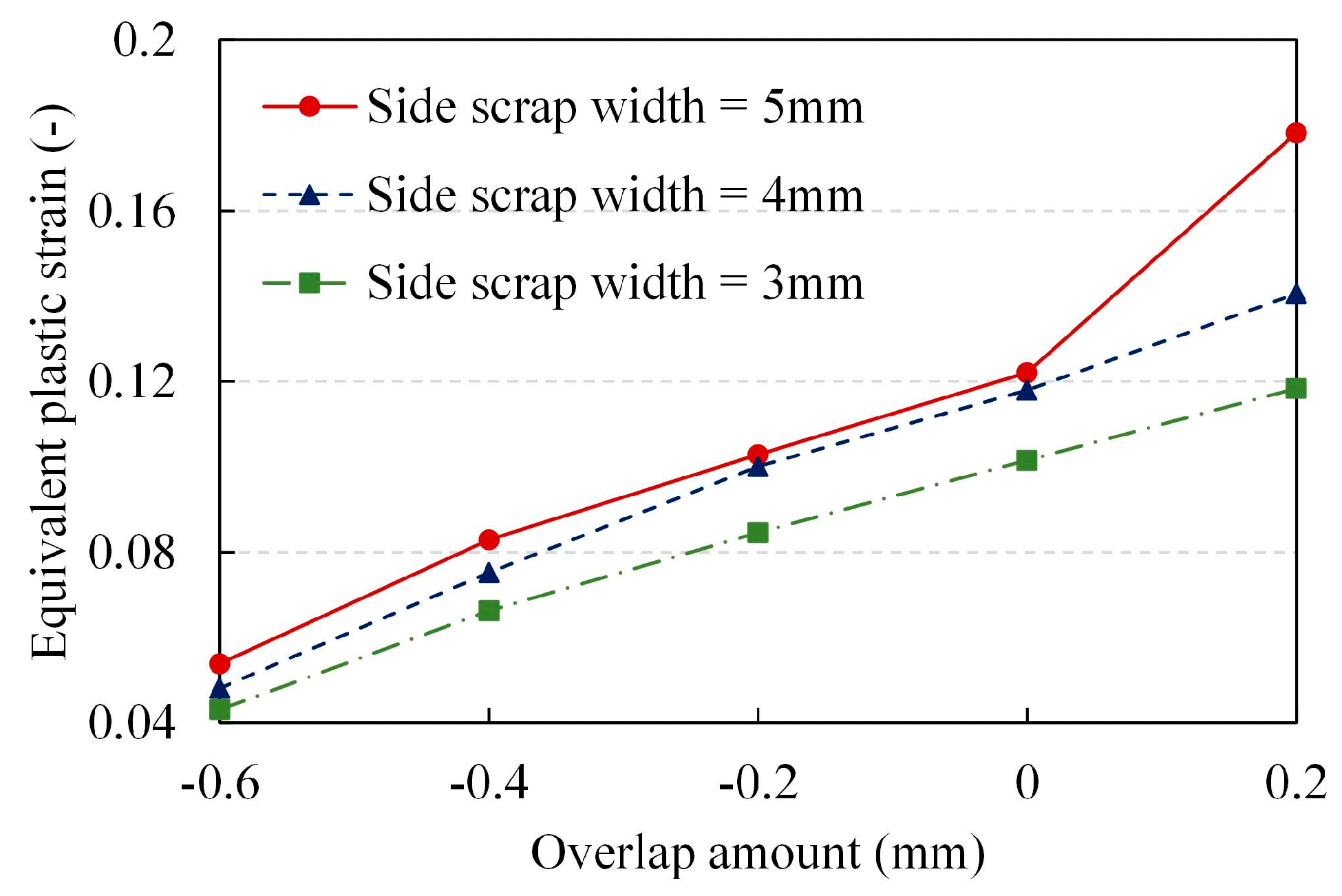
The maximum equivalent plastic strain of the trimmed unit in the trimming process under different overlap amounts is extracted as shown in Figure 9 (fixed I = 0.5 mm, T = 1 mm). In the case where the side scrap was not successfully trimmed, i.e., the equivalent plastic strain of the trimmed unit did not reach 0.178 during the trimming process, observing the calculated results at each overlap amount. It was found that with wider side scrap widths, the equivalent plastic strain of the trimmed strip was larger. This is consistent with the previous conclusion on the effect of side scrap width on the trimming process. If the side scrap width is certain, the equivalent plastic strain of the strip during trimming increases with the increase of the overlap amount of the side trimmer.
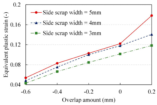
Figure 9.
Maximum equivalent plastic strain for trimming processes with different overlap amounts and side scrap width.
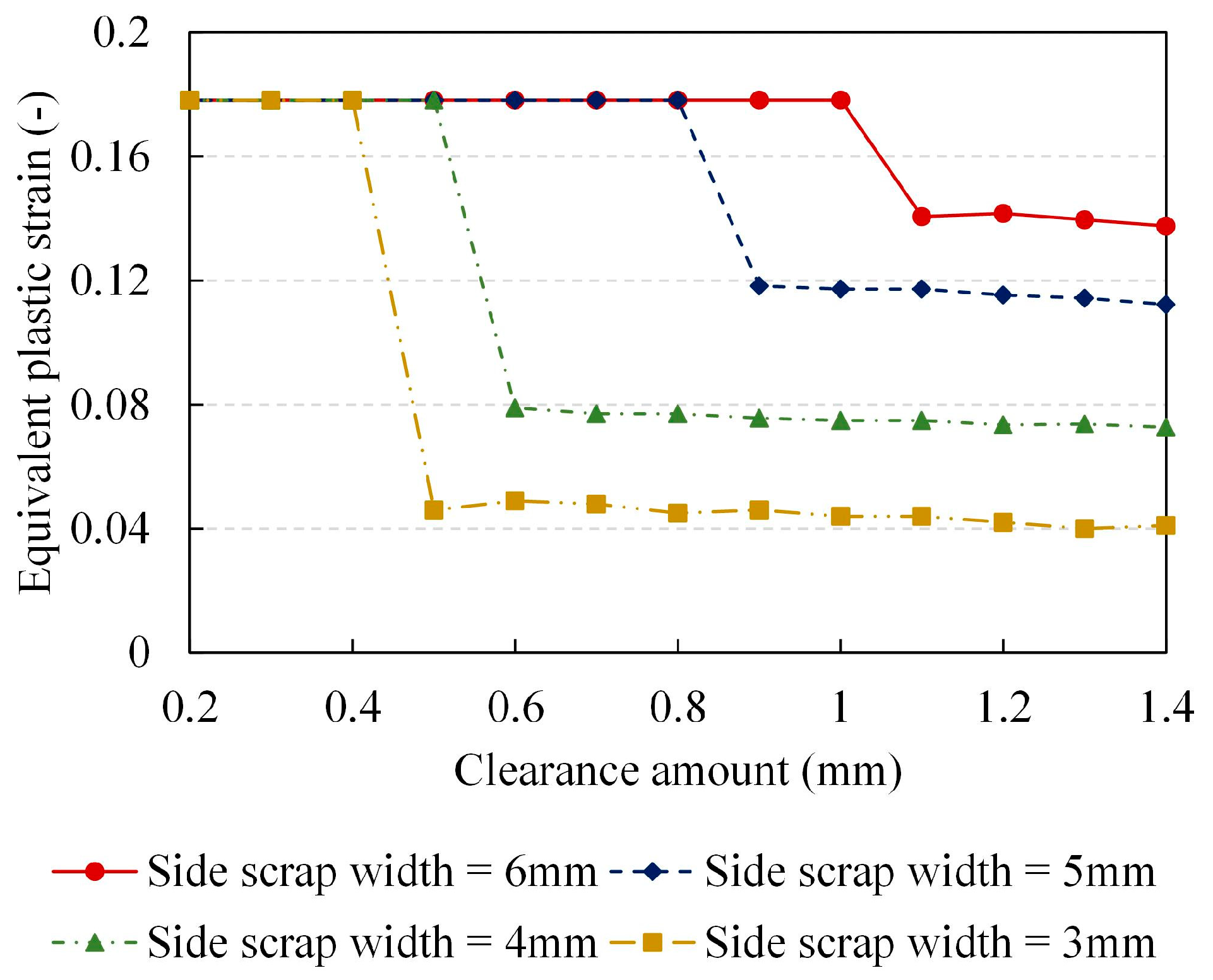
The maximum equivalent plastic strain of the trimmed unit during the trimming process with different clearance settings is shown in Figure 10 (fixed I = 0.5 mm, T = 1 mm). It is observed that when the side scrap width is certain, the equivalent plastic strain of the trimmed unit appears to be significantly smaller after the clearance amount increases to a certain degree, and then tends to be smooth, but tends to become smaller. The effect of side scrap width variation on the equivalent plastic strain is consistent with the Section 4.1. Overall, the increase in the amount of clearance amount is not conducive to the smooth trimming of the side scrap, and the maximum equivalent plastic strain of the trimmed strip during the trimming process decreases with the increase in the clearance amount of the side trimmer.

Figure 10.
Maximum equivalent plastic strain for trimming processes with different clearance amounts and side scrap width.
4.3. Effect of Strip Specification on the Trimming Process of Side Trimmer
The factors that affect the trimming process of the side trimmer are also the specifications of the strip, including the thickness and material properties of the strip. Therefore, the working conditions of the strip trimming process with different thicknesses and material properties are designed for simulation calculation.
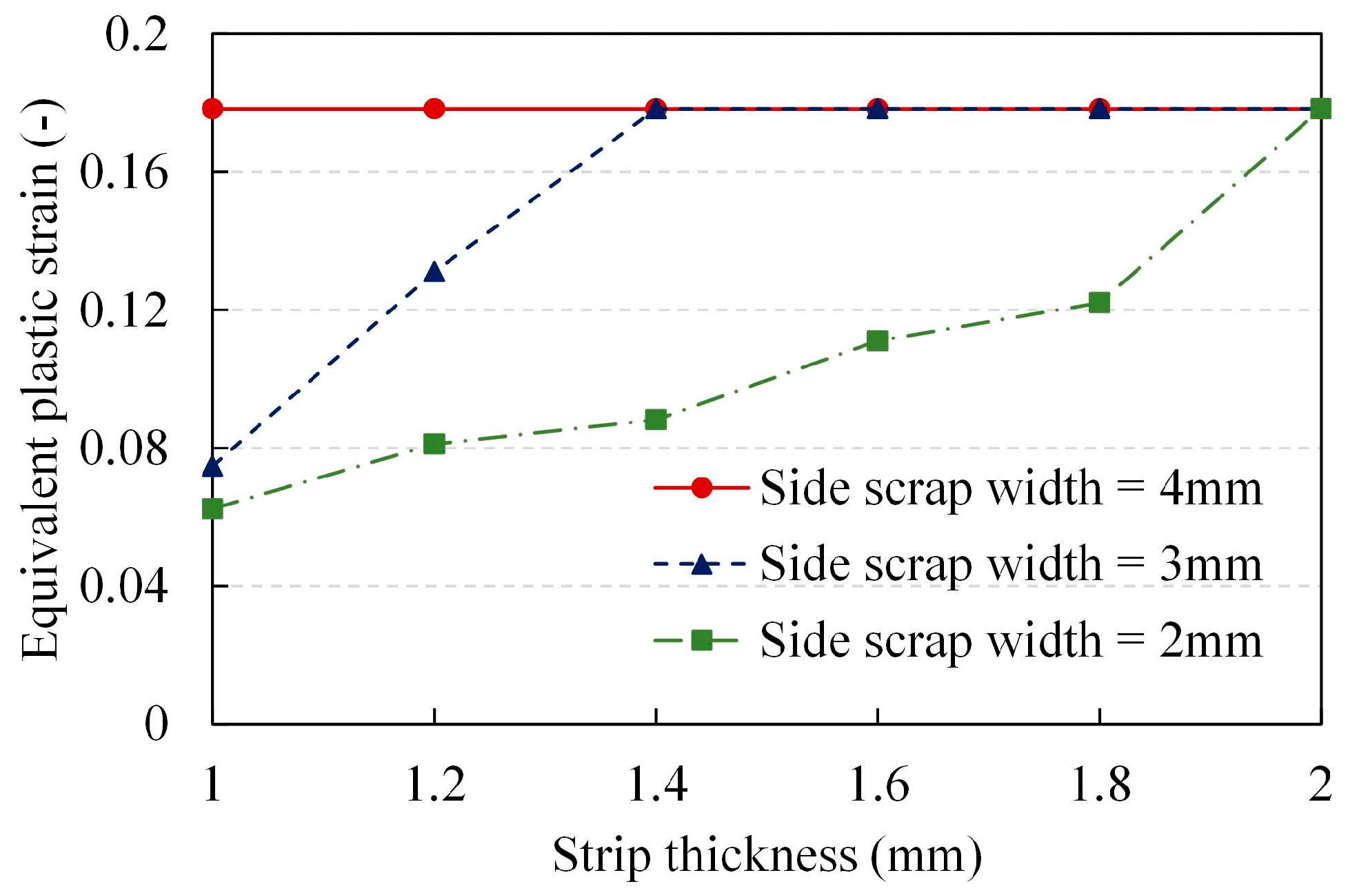
The maximum equivalent plastic strains of the corresponding units during the trimming of the strip of different thicknesses at different side scrap width settings are extracted as shown in Figure 11 (fixed S = 0 mm, I = 1 mm). It is observed that when the equivalent plastic strain of the trimmed unit does not reach 0.178 during the trimming process, the equivalent plastic strain of the trimmed strip increases with the increase in the strip thickness if the side scrap width is certain, i.e., the thinner the strip is, the more likely the side scrap blockage phenomenon occurs. When the strip thickness is certain, the wider the width of the side scrap, the greater the maximum equivalent plastic strain of the trimmed unit; that is, increasing the width of the side scrap is beneficial to the smooth trimming of the side scrap.

Figure 11.
Maximum equivalent plastic strain for trimming processes with different strip thickness and side scrap width.
In terms of material properties, yield strength as an important parameter to characterize the material, is modified and designed for working conditions in this paper to analyze its effect on the trimming process. With the fixed clearance amount of 1.2 mm, overlap amount of −0.4 mm, strip thickness of 2 mm, and side scrap width of 7 mm, the strip yield strength is set in the range of 200~600 MPa for simulation calculation. The equivalent plastic strain cloud for a strip with a yield strength of 600 MPa after trimming is shown in Figure 12a. It is observed that the units in the upper and lower layers at the trimmed position are not destroyed, while the units in the middle layer are destroyed during the trimming process. Combined with the data on the maximum equivalent plastic strain during the trimming process in Figure 12b, when the yield strength of the material is large, a phenomenon occurs where the inside of the strip is destroyed due to the accumulation of plastic deformation, while the outside is not destroyed. The maximum equivalent plastic strain in the trimming process for the units in the upper and lower layers decreases as the yield strength becomes larger. The higher the yield strength of the strip the less conducive to a smooth trimming process.

Figure 12.
(a) Schematic representation of different layer cells of the trimmed strip and (b) maximum equivalent plastic strain for trimming processes with different material properties.
In summary, the effects of each influencing factor on the trimming process, including side scrap width, overlap amount, clearance amount, strip thickness, and yield strength, were analyzed by designing different working conditions for simulation calculations. Observing the variation in the maximum equivalent plastic strain of the trimmed strip in the trimming process with the variation in each influencing factor, it was found that it is beneficial for the trimming process to have a larger set of the side scrap width, overlap amount, and strip thickness. While for the larger amount of clearance and the yield strength of the strip, it is harder for the side scrap to be trimmed smoothly and the risk of side scrap blockage is higher.
5. The Side Scrap Blockage Pre-Control Model of Side Trimmer
5.1. Identification of the Scrap Blockage Risk
According to the results of the above analysis, although changes in the structural parameters of the side trimmer and strip specifications cause changes in the equivalent plastic strain of the strip during the trimming process, they do not change the influence law of the side scrap width on the trimming process. That is, the size of the side scrap width will affect the trimming process, while the side scrap width is wider the more conducive to smooth trimming, and vice versa the risk of side scrap blockage will increase. Therefore, the risk of side scrap blockage can be determined by monitoring the real-time status of the side scrap width during the strip running process.
The structural parameters of the side trimmer have been set by past research and long-term accumulation in the industrial practice, and have been able to achieve reasonable settings according to the actual specifications of the strip. The main causes of side scrap blockage failures in the side trimmer at present are fluctuations in the quality of the hot-rolled strip and changes in the actual running state of the strip. With the improvement of information technology resources construction for the strip production process, it has been able to realize the deployment of data resources across processes. Based on the history of blockage failure of the side trimmer, the actual side scrap width at the time of blockage is calculated by extracting the width data of the corresponding hot-rolled strip and combining it with the side trimmer exit width and CPC deviation data. After collation, the blockage failure sample data can be obtained as in Equation (4).
where B is the 5-dimensional data sample set; S is the overlap amount; I is the clearance amount; T is the strip thickness; G is the steel grade, which is used to distinguish the difference in mechanical properties of different materials of strip; w is the width of the side scrap when the blockage failure occurs; and m is the total number of samples.
Usually, the structural parameters of the side trimmer are set the same for the same steel grade and the same side scrap width setting for trimming, so it is reasonable and realistic to determine the side scrap width threshold based on actual production data statistics. For the above blockage failure sample dataset, there will be a phenomenon that the data in the first four dimensions are consistent, while the actual side scrap width in the fifth dimension of blockage is different. The maximum value of the actual side scrap width in such data are taken as the base side scrap width threshold, and for safety, a safety factor is multiplied on this basis to obtain the final side scrap width threshold, as shown in Equation (5).
where WT is the side scrap width threshold; η is the safety factor, usually taken as 1.3~1.5; wmax is the base side scrap width threshold obtained from the historical blockage failure records.
The side scrap blockage failure of the strip due to the narrow width of the side scrap can be divided into two categories: (1) caused by the strip state such as the width change or sickle-shape bending of the strip; (2) caused by the actual running state of the strip in the inlet section of the PL-TCM, such as the strip deviation. Currently, the quality data of hot-rolled strips can be obtained at the PL-TCM, including strip width, centerline deviation, etc. Based on information such as the full-length width and centerline deviation of the hot-rolled strip, combined with the setting of the side trimmer opening size, areas with narrower side scrap widths can be identified and the risk of side scrap blockage can be determined.
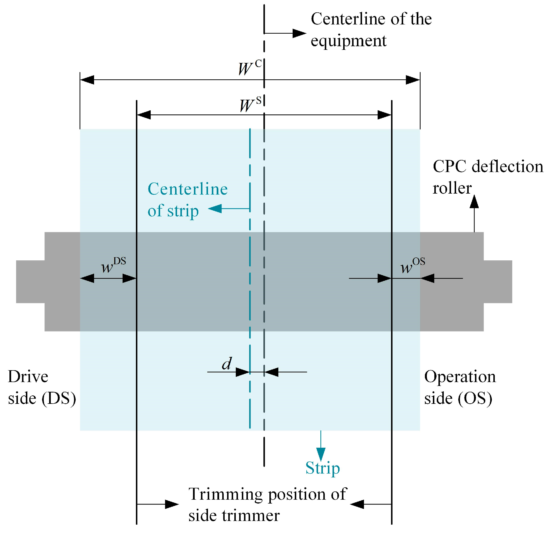
Figure 13 shows a schematic representation of each dimension of the strip during operation. The steps to identify the two types of side scrap blockage risks mentioned above are as follows:
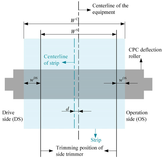
Figure 13.
Schematic of each dimension during strip operation.
(1) According to the cold rolling production plan, the hot state width data of the full length of the strip under the plan measured in the hot rolling process is obtained, and the full-length cold state width of the strip is calculated as shown in Equation (6).
where WiC and WiH are the cold and hot widths of the strip; i is the position in the length direction of the strip; α is based on empirical data from industrial sites on the changes in width dimensions of strips after hot rolled and after cooling, usually taking a value of 1.01 to 1.02.
(2) The side trimmer width setting and side scrap width threshold are obtained for this strip, the trim amount is calculated on one side, and it is determine if there is a risk of side scrap blockage caused by strip width variation according to Equation (7).
where wi is the total side scrap width on both sides of the strip; WiC is the cold width of the strip; WS is the side trimmer width setting value; and WT is the side scrap width threshold.
(3) The sickle-shaped bending of the strip can be characterized by the centerline deviation data of the hot-rolled strip. Obtaining the centerline deviation data for the full length of the hot-rolled strip, calculating the steady-state deviation for the full length, and on this basis calculating the relative deviation for the full length of the strip, as shown in Equation (8).
where CiR is the strip full-length relative deviation; Ci is the strip full-length centerline deviation data; i is the position in the strip length direction; and n is the total strip length.
(4) Based on the above calculation to obtain the hot-rolled strip full-length relative deviation, calculate the side scrap width considering the strip relative deviation and determine whether there is a risk of side scrap blockage caused by the bending of the strip sickle-shape by Equation (9).
where wiC is the width of the side scrap considering the relative deviation of the hot-rolled strip.
(5) The above is the identification of static side scrap blockage risk considering only the shape characteristics of the hot-rolled strip, while the actual risk identification also needs to consider the operating condition of the strip. The CPC deflection roller has the function of detecting the deviation of the strip, and the deviation data of the strip obtain from the deflection roller arranged in front of the side trimmer is collected in real time, so that the deviation data can be used to calculate the side scrap width on both sides of the strip during the actual operation and to identify the dynamic side scrap blockage risk. When the side scrap width on one side is less than the risk threshold, there is a risk of side scrap blockage, and the side scrap width on both sides of the strip during operation is calculated as shown in Equation (10).
where wir is the real-time side scrap width on the side of the strip with higher risk of blockage; dr is the real-time strip deviation obtained from the CPC deflection roller.
The above is the side scrap blockage risk identification function of the side trimmer. Accordingly, the speed reduction strategy of strip operation can be designed according to the risk identification results, and when the risk position is close to the side trimmer, by reducing the trim speed to achieve the purpose of smooth transition.
5.2. Speed Reduction Strategy
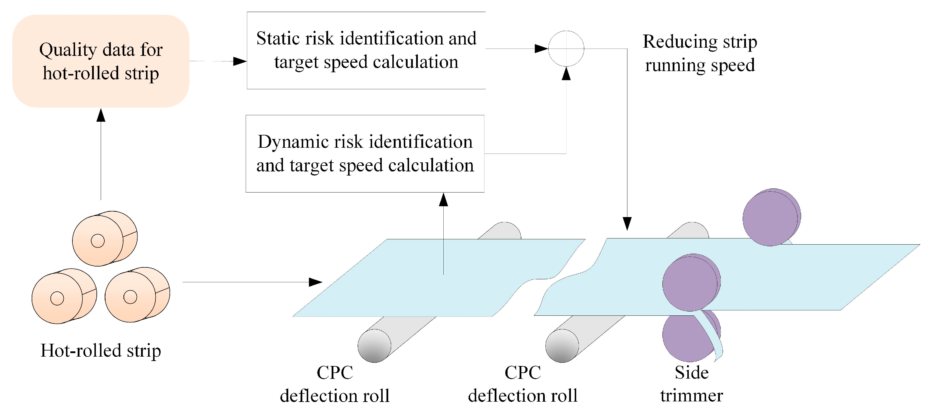
In the inlet section of the PL-TCM, the hot-rolled strip may deviate from the centerline due to asymmetric shapes such as sickle-shape bending and strip wedge. Therefore, a center position control system (CPC) is installed at the inlet section of the PL-TCM to correct the strip deviation during operation. The specific implementation equipment is the CPC deflection roller, which is based on the principle that there are corresponding sensors for detecting deviation signals on both sides of the strip, which can detect the deviation status of the strip in real-time. When the strip is deviating, the deviation signal is amplified and converted to drive the hydraulic cylinder that controls the angle of the deflection roller, so that the deflection roller forms a turning angle and changes the friction force on both sides of the operation and transmission when the strip passes through the deflection roller, thus changing the running trajectory of the strip and achieving the effect of deflection correction. According to the industrial field experience, the deflection correction ability of CPC is related to the running speed of the strip, when the strip is running at a low speed, it has a better deflection correction effect.
Accordingly, when the strip has a serious deviation phenomenon, the deflection correction capacity of the CPC deflection roller can be fully utilized by reducing the running speed of the strip. This balances the side scrap width on both sides of the strip, reduces the probability of side scrap blockage in the side trimmer, and effectively improves the stability of the inlet section of the PL-TCM. As shown in Figure 1 for the equipment arrangement of the PL-TCM, there are two CPC deflection rollers between the No. 2 looper and the side trimmer, where the deflection roller closer to the s No. 2 looper is named CPC-1 and the deflection roller closer to the side trimmer is named CPC-2. Based on the operation status of the strip at the above two deflection roller positions, the risk of blockage can be identified. The actual distance between CPC-2 and the side trimmer is too close, so if this identification result is used as the basis for speed control, it will be too late to effectively reduce the speed in order to adjust the strip’s deflection status, and therefore the identification result of CPC-1 will be used as the basis for speed control.
After effectively identifying the three types of side scrap blockage risk described in the previous section, the risk position needs to be saved in combination with the relative position positioning function of the strip based on weld position detection, and speed reduction is carried out when the risk position runs near the side trimmer. For the static risk caused by the narrowing of strip width, the target speed is 30 m/min for speed reduction to achieve the purpose of smooth transition. For the side scrap blockage risk caused by sickle-shaped bending of the strip and position deviation during operation, the target speed of the strip can be calculated according to the width of the scrap, and the calculation method is shown in Equation (11).
where and are the target speeds for the side scrap blockage risk caused by sickle-shaped bending of the strip and position deviation during operation, respectively, and is the current operation speed of the strip. In summary, the structure of the speed reduction strategy for the side scrap blockage risk is shown in Figure 14.
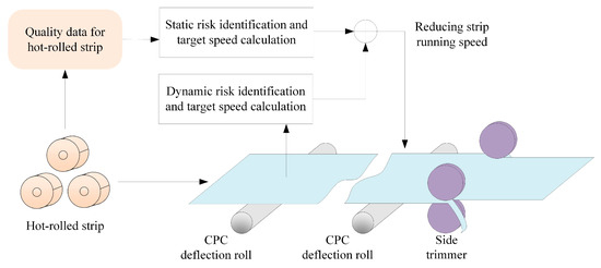
Figure 14.
Structure of the speed reduction strategy.
Accordingly, when the risk of blockage is identified during the trimming process, the deviation state of the strip can be corrected by reducing the trimming speed to avoid the risk. For the risk of side scrap blockage caused by narrowing strip width, reduced trimming speed can also achieve a smooth transition. The above risk identification functions, combined with the speed reduction strategy, form the side scrap blockage pre-control model.
5.3. Industrial Applications
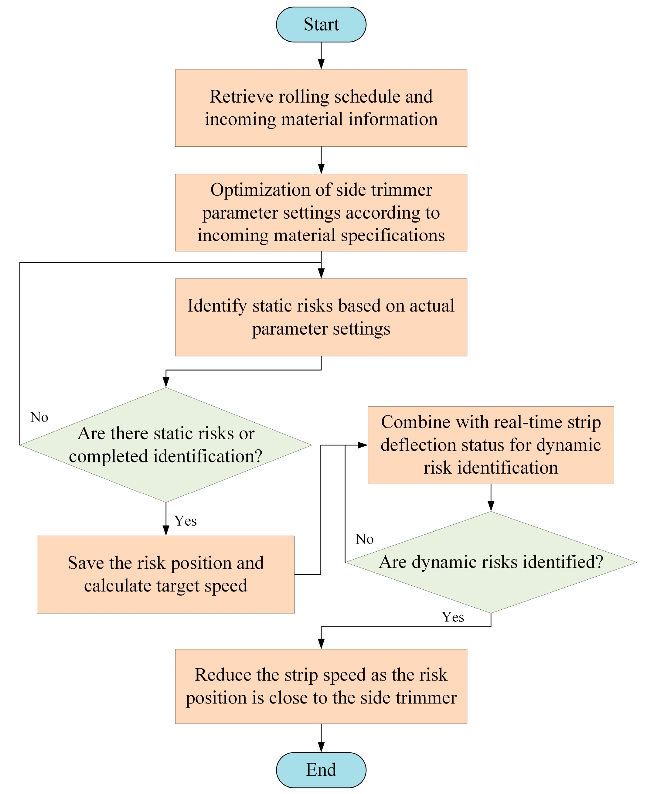
The experimental part of this research was performed in the industry, where the side scrap blockage pre-control model was applied to a PL-TCM. When the hot-rolled strip enters the production plan scheduling of the PL-TCM, the full-length width and centerline deviation data of the strip are extracted and the static side scrap blockage risk is first identified. When the strip runs in the inlet section of the PL-TCM after pay-off, the dynamic side scrap blockage risk is identified in combination with the detection of the real-time deviation of the CPC deflection rolls. Once the risk identification is complete, then the speed reduction intervention is performed on the risk position and the implementation process of the model is shown in Figure 15.
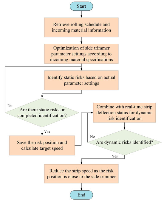
Figure 15.
Implementation process of the side scrap blockage pre-control model.
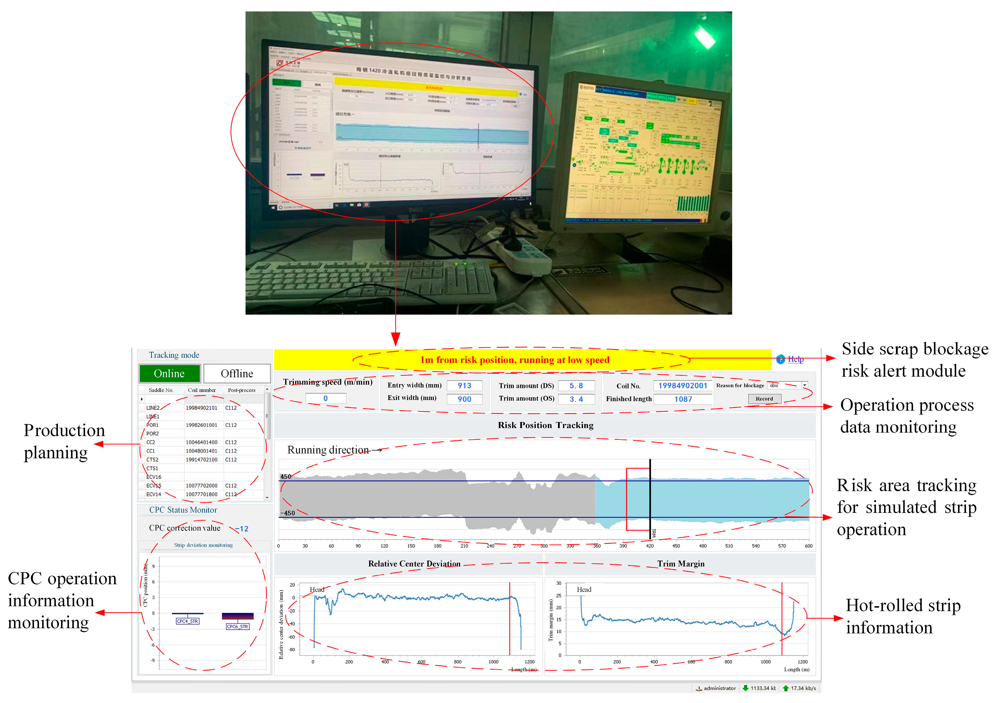
The application of the pre-control model can effectively identify the side scrap blockage risk of the side trimmer and calculate the target operating speed according to the risk identification results. Accordingly, the operating speed is reduced when the risk area is close to the side trimmer to reduce the number of side scrap blockage failures, thus reducing unscheduled downtime and improving the operating stability of the PL-TCM, which plays a role in supporting production decisions. As shown in Figure 16, the interface design of the side scrap blockage risk identification model mainly involves (1) production planning; (2) CPC operation information monitoring; (3) side scrap blockage risk alert module; (4) operation process data monitoring; and (5) visualization of information such as side scrap blockage risk area tracking for simulated strip operation. The identification of side scrap blockage risk areas is visualized and intuitive, providing convenient reference as well as practical value for the use of side trimmer operators.
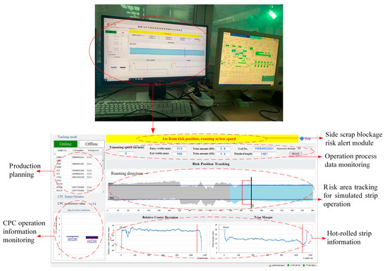
Figure 16.
Interface of the side scrap blockage pre-control model.
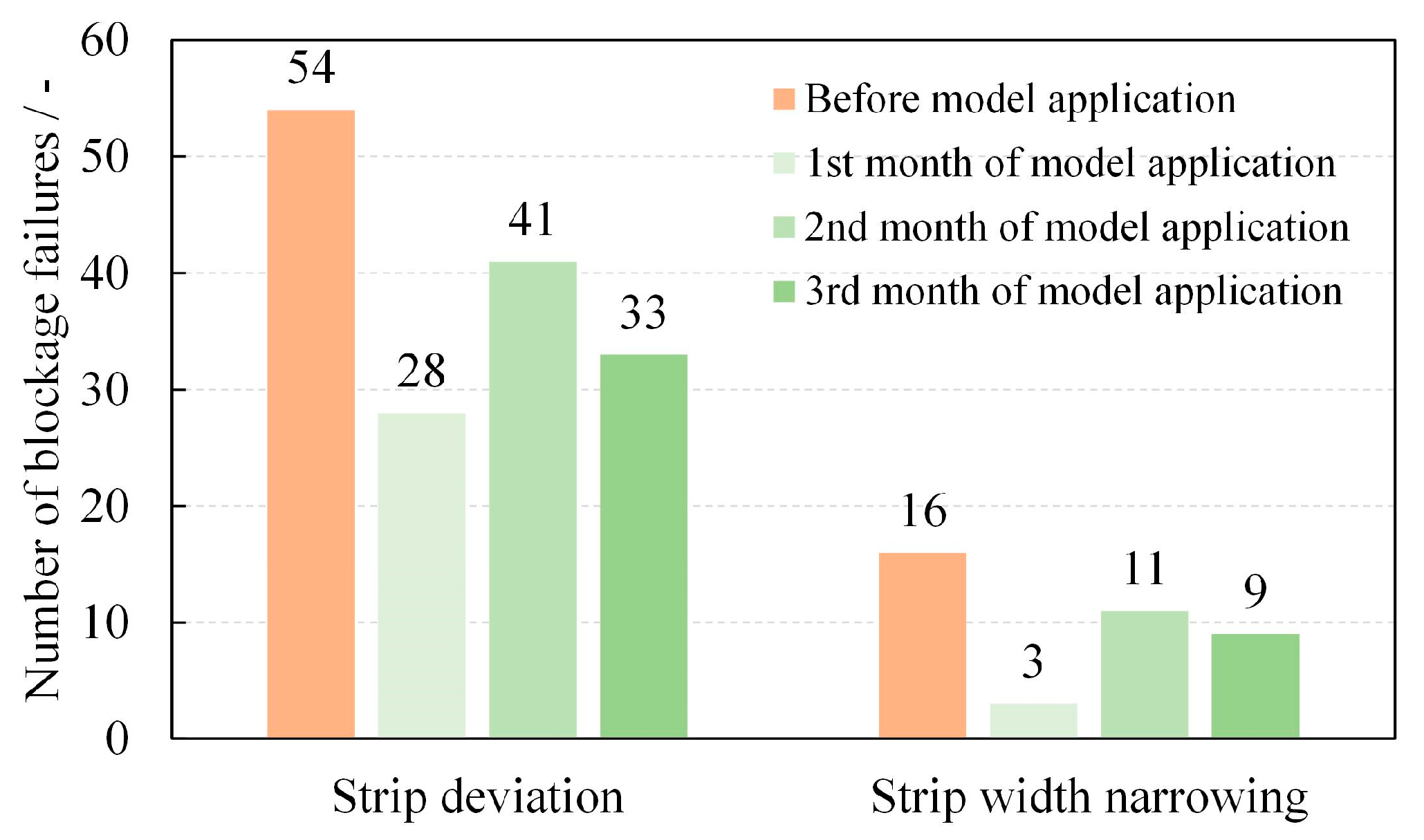
The side scrap blockage pre-control model has been applied online in a PL-TCM, which has a stable operation process and accurately identifies the blockage risk areas and carries out the corresponding speed reduction and warning prompts, effectively reducing the number of side scrap blockage failures during production line operation. At the same time, the operator can pay attention to the strip operation and trimming status in real time according to the HMI. To avoid experimental chance, three one-month model runs were conducted, interspersed with a production phase in which the pre-control model was not commissioned for the same one-month period, i.e., one month with the pre-control model and the following month without it, repeated three times. As shown in Figure 17, after the application of the side scrap blockage risk identification model, there is a significant reduction in blockage failures compared with the same length of time before the application. The number of side scrap blockage failures caused by the narrowing of the hot-rolled strip width was reduced from an average of 16 per month to 7; the number of blockage failures caused by strip deviation during running was reduced from an average of 54 per month to 34. After the model was applied, the side scrap blockage failure was reduced by 40.5% in the same length of time, achieving the expected results.
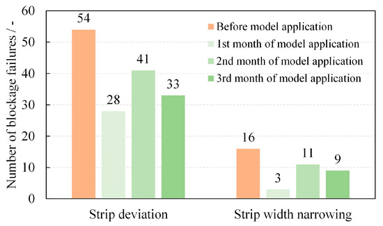
Figure 17.
The number of blockage failures before and after the use of the pre-control model.
6. Conclusions
In this paper, focusing on the side scrap blockage failure that is prone to occur during the trimming process of the side trimmer at the entrance section of the PL-TCM, a corresponding finite element model is established, according to which the influence of each parameter on the trimming process is analyzed. Based on this, the side scrap blockage risk identification function and speed reduction strategy of side trimmer are designed to achieve the pre-control of side scrap blockage. After verifying the effect by practical application in industrial sites, the following conclusions were obtained:
(1) The larger the set amount of side scrap width, overlap, and strip thickness, the greater the equivalent plastic strain at the trimmed position and the more conducive to a smooth trimming process. The larger the amount of clearance and the yield strength of the strip, the smaller the equivalent plastic strain at the trimmed position, which is less conducive to the trimming process and has a higher risk of side scrap blockage.
(2) Different side trimmer construction parameters and strip specifications affect the trimming process but do not change the law of the influence of the side scrap width on the trimming process. On this basis, the static and dynamic risks of blockage faults are identified and establish a side scrap blockage risk identification model for side trimmer, and the strip speed reduction strategy is designed accordingly.
(3) By applying the side scrap blockage pre-control model of the side trimmer to a PL-TCM, the trim speed is reduced when the risk position is close to the side trimmer, so as to achieve the purpose of risk avoidance and smooth transition. After the model was applied, the total reduction rate of blockage failure reached 40.5%, which achieved the expectation of the application effect.
Author Contributions
Conceptualization, methodology, funding acquisition and writing—review and editing, Z.W.; methodology and writing—original draft preparation, X.W.; software and validation Q.Y.; validation and funding acquisition, D.X.; resources and investigation, J.Z. All authors have read and agreed to the published version of the manuscript.
Funding
This work was funded by the National Natural Science Foundation of China [grant number 51975043], China Postdoctoral Science Foundation [grant number 2021M69035].
Data Availability Statement
Not applicable.
Conflicts of Interest
The funders had no role in the design of the study; in the collection, analyses, or interpretation of data; in the writing of the manuscript; or in the decision to publish the results.
References
- Chen, J.S.; Zhou, G.P. Development of control model for basic automation in pickling mills. J. Iron Steel Res. 2017, 29, 397–401. [Google Scholar]
- Liu, Y.; Wang, X.; Sun, J.; Liu, G.; Li, H.; Ji, Y. Strip Thickness and Profile–Flatness Prediction in Tandem Hot Rolling Process Using Mechanism Model-Guided Machine Learning. Steel Res. Int. 2023, 94, 2200447. [Google Scholar] [CrossRef]
- Li, L.; Xie, H.; Li, X.; Zhang, T.; Pan, D.; Huo, M.; Chen, F.; Liu, T.; Shi, K.; Jiang, Z. Numerical Analysis of the Effect of Work Roll Bending on Strip Crown During Tandem Hot Rolling. Int. J. Appl. Mech. 2022, 14, 2250052. [Google Scholar] [CrossRef]
- Li, L.; Xie, H.; Liu, T.; Huo, M.; Liu, X.; Li, X.; Shi, K.; Li, J.; Liu, H.; Sun, L.; et al. Influence mechanism of rolling force on strip shape during tandem hot rolling using a novel 3D multi-stand coupled thermo-mechanical FE model. J. Manuf. Process. 2022, 81, 505–521. [Google Scholar] [CrossRef]
- Zhao, Z.; Song, R.; Wang, Y.; Hu, C. Lateral cracks damaging the stability of tensile sheet during tandem rolling conveying. Eng. Fail. Anal. 2022, 138, 106358. [Google Scholar] [CrossRef]
- Li, L.; Xie, H.; Zhang, T.; Huo, M.; Pan, D.; Wu, H.; Chen, F.; Liu, T.; Li, X.; Liu, X.; et al. Understanding the regulation ability of roll bending on strip shape in a CVC-6 tandem cold mill using a 3D multiple stand FE model. J. Manuf. Process. 2023, 101, 1013–1031. [Google Scholar] [CrossRef]
- Ji, J.P.; Sun, L.; Li, J.W. Precision Influence of Sickle-Like Curve of Hot Rolled Strip on Rotary Shear’s Cutting. Adv. Mater. Res. 2012, 421, 51–55. [Google Scholar] [CrossRef]
- Bai, Z.H.; Xing, B.X.; Qian, C.; Liu, Y.X.; Wang, R.; Chang, J.L. Comprehensive optimization technology of front and back tensions for disc shear in strip trimming process. J. Plast. Eng. 2017, 24, 82–87. [Google Scholar]
- Xu, K.; Xia, M.; Liu, J.; Wang, C.; Wang, Q.Y.; Ren, S.B. Simulation of stress on shear blade of disc shear based on Gissmo material failure criterion. J. Plast. Eng. 2021, 28, 110–116. [Google Scholar]
- Jing, Q.P.; Jia, H.L.; Shuang, Y.H.; Yang, B.; Jin, L. Numerical simulation and experimental study of the shearing process on trimming disc shear. J. Plast. Eng. 2010, 17, 32–36. [Google Scholar]
- Chen, B.; Liu, S.H.; Yang, J. Simulation research for strip shearing section level distribution. Appl. Mech. Mater. 2012, 157, 231–235. [Google Scholar] [CrossRef]
- Ma, L.F.; Huang, Q.X.; Huang, Z.Q.; Chu, Z.B.; Han, H.Y. Energetic parameter test on disc shear of plate and establishment of the best blade clearance mathematical model. Chin. J. Eng. Des. 2012, 19, 434–439. [Google Scholar]
- Li, S.C. Research and Practice in Side Trimming Technology of IF Steel. Iron Steel 2014, 49, 85–89. [Google Scholar]
- Li, D.F.; Wu, S.L.; Liu, W.J. Numerical analysis of shear force of side trimmer based on ANSYS/LS-DYNA. J. Plast. Eng. 2016, 23, 56–61. [Google Scholar]
- Rasool, M.; Singha, M.K. A finite element study on the nonlinear behavior of rectangular shear panels. Thin-Walled Struct. 2016, 104, 248–258. [Google Scholar] [CrossRef]
- Zhu, Y.; Yan, Q.; Lu, J. Fault diagnosis method for disc slitting machine based on wavelet packet transform and support vector machine. Int. J. Comput. Integr. Manuf. 2020, 33, 1118–1128. [Google Scholar] [CrossRef]
- Jun, Z.; Qiusheng, Y.; Jiabin, L.; Zhang, X.W.; Ou, Y.B. Simulation research on wear mechanism of disc cutter in slitting process. J. Plast. Eng. 2019, 26, 259–266. [Google Scholar]
- Yan, Q. New technology analysis on metal strips no-burr precision slitting. China Mech. Eng. 2012, 23, 2102. [Google Scholar]
- Yan, Q.; Lai, Z.; Lu, J.; Li, Z.R.; Ou, Y.J.; Xie, Z.P. Influence of clearance on disc slitting surface morphology for galvanized steel sheet. J. Plast. Eng. 2014, 21, 69–73. [Google Scholar]
- Yan, Q.S.; Shi, X.J.; Lu, J.B. Studying Plastic Deformation in Burr-free Disc Slitting Process of Metal Sheet. Mech. Sci. Technol. Aerosp. Eng. 2016, 35, 98–103. [Google Scholar]
- Zeng, J.; Lu, J.B.; Yan, Q.S.; Li, S. Influence of blade profile of disc cutter on numerical simulation of the disc slitting process. In AIP Conference Proceedings; AIP Publishing: Bristol, UK, 2015; Volume 1653. [Google Scholar]
- Feng, W.Y.; Yan, Q.S.; Lu, J.B.; Li, H.Y. Influence of lateral clearance on the slitting surface morphology in the disc burrfree slitting. J. Plast. Eng. 2016, 23, 126–130. [Google Scholar]
- Li, J.; Zhang, T.; Wang, S.; Cheng, J.; Wang, W. Mechanism and Method of Testing Fracture Toughness and Impact Absorbed Energy of Ductile Metals by Spherical Indentation Tests. Chin. J. Mech. Eng. 2023, 36, 108. [Google Scholar] [CrossRef]
- Khademi, M.; Naeini, H.M.; Mirnia, M.J.; Kasaei, M.M.; da Silva, L.F. Fracture prediction of AA6061-T6 sheet in bending process using Gurson–Tvergaard–Needleman model. Proc. Inst. Mech. Eng. Part L J. Mater. Des. Appl. 2022, 14644207221134504. [Google Scholar] [CrossRef]
- Guo, M.; Tao, J.; Wu, C.; Luo, C.; Lin, Z. High-speed grinding fracture mechanism of Cf/SiC composite considering interfacial strength and anisotropy. Ceram. Int. 2023, 49, 2600–2612. [Google Scholar] [CrossRef]
- Zhao, Z.; Ji, H.; Zhong, Y.; Luo, C.; Lin, Z. Mechanical Properties and Fracture Behavior of a TC4 Titanium Alloy Sheet. Materials 2022, 15, 8589. [Google Scholar] [CrossRef]
- Faura, F.; Garcıa, A.; Estrems, M. Finite element analysis of optimum clearance in the blanking process. J. Mater. Process. Technol. 1998, 80, 121–125. [Google Scholar] [CrossRef]
- Zhang, D.W.; Yang, H. Numerical study of the friction effects on the metal flow under local loading way. Int. J. Adv. Manuf. Technol. 2013, 68, 1339–1350. [Google Scholar] [CrossRef]
- Liu, H.; Xu, X.; Zhang, J.; Liu, Z.; He, Y.; Zhao, W.; Liu, Z. The state of the art for numerical simulations of the effect of the microstructure and its evolution in the metal-cutting processes. Int. J. Mach. Tools Manuf. 2022, 177, 103890. [Google Scholar] [CrossRef]
- Chai, C.-g.; Feng, X.-l.; Wu, H.-j.; Guo, C.; Zhang, S.; Haung, F.L. Numerical Simulation of Dynamic Shear Properties of AerMet100 Steel. Trans. Beijing Inst. Technol. 2014, 34, 1223–1228. [Google Scholar]
- Moemeni, S.; Zarei-Hanzaki, A.; Abedi, H.R.; Torabinejad, V. The application of shear compression specimen to study shear deformation behavior of AZ31 Mg alloy at high temperatures and quasi-static regime. Exp. Mech. 2012, 52, 629–636. [Google Scholar] [CrossRef]
- Kwak, T.S.; Kim, Y.J.; Seo, M.K.; Bae, W. The effect of V-ring indenter on the sheared surface in the fine-blanking process of pawl. J. Mater. Process. Technol. 2003, 143, 656–661. [Google Scholar] [CrossRef]
- Zhu, L.; Estefen, S.F.; Lourenco, M.I. Fracture criteria applied to numerical simulation of blowout preventer ram shearing. Eng. Fail. Anal. 2020, 114, 104596. [Google Scholar] [CrossRef]
- Lorenz, S.J.; Sadeghi, F.; Sharma, A.; Wang, C.; Wang, B. An investigation into various failure criteria on rolling contact fatigue through an improved probabilistic model. Tribol. Int. 2023, 188, 108875. [Google Scholar] [CrossRef]
- Khadke, A.; Ghosh, S.; Li, M. Numerical simulations and design of shearing process for aluminum alloys. J. Manuf. Sci. Eng. 2005, 127, 612–621. [Google Scholar] [CrossRef]
- Hambli, R.; Reszka, M. Fracture criteria identification using an inverse technique method and blanking experiment. Int. J. Mech. Sci. 2002, 44, 1349–1361. [Google Scholar] [CrossRef]
- Bai, Y.; Wierzbicki, T. Application of extended Mohr–Coulomb criterion to ductile fracture. Int. J. Fract. 2010, 161, 1–20. [Google Scholar] [CrossRef]
- Lixi, L.; Qingli, Z.; Jian, Z.; Li, Z.Q. Effects of stress triaxiality and lode parameter on ductile fracture in aluminum alloy. Rare Met. Mater. Eng. 2019, 48, 433–439. [Google Scholar]
- Liu, B.; Zhou, Y. Damage failure mechanism of unidirectional fiber reinforced SiCf/SiC composites under uniaxial tension. Compos. Struct. 2023, 307, 116610. [Google Scholar] [CrossRef]
- Peshekhodov, I.; Dykiert, M.; Vucetic, M.; Behrens, B.-A. Evaluation of common tests for fracture characterisation of advanced high-strength sheet steels with the help of the FEA. In IOP Conference Series: Materials Science and Engineering; IOP Publishing: Bristol, UK, 2016; Volume 159, p. 012014. [Google Scholar]
- Dong, D.; Liu, Y.; Yang, Y.; Li, J.; Ma, M.; Jiang, T. Microstructure and dynamic tensile behavior of DP600 dual phase steel joint by laser welding. Mater. Sci. Eng. A 2014, 594, 17–25. [Google Scholar] [CrossRef]


Disclaimer/Publisher’s Note: The statements, opinions and data contained in all publications are solely those of the individual author(s) and contributor(s) and not of MDPI and/or the editor(s). MDPI and/or the editor(s) disclaim responsibility for any injury to people or property resulting from any ideas, methods, instructions or products referred to in the content. |
© 2023 by the authors. Licensee MDPI, Basel, Switzerland. This article is an open access article distributed under the terms and conditions of the Creative Commons Attribution (CC BY) license (https://creativecommons.org/licenses/by/4.0/).