Article

Diffusion Welding of Surface Treated Alloy 800H

1
Department of Materials Science and Engineering, Chungnam National University, Daejeon 34134, Republic of Korea
2
Advanced Fuel Technology Development Division, Korea Atomic Energy Research Institute, Daejeon 34057, Republic of Korea
*
Author to whom correspondence should be addressed.
Metals 2023, 13(10), 1727; https://doi.org/10.3390/met13101727
Submission received: 17 August 2023 / Revised: 3 September 2023 / Accepted: 7 October 2023 / Published: 11 October 2023
(This article belongs to the Section Welding and Joining)

Abstract

:
Diffusion welding of heat-resistant alloys has attracted interest in the manufacturing of components with complex configurations. Controlling secondary precipitates along the interface is necessary to enhance the quality of the diffusion welding. Surface treatment to increase the solubility product (Ksp) of Ti-rich carbide is proposed to accomplish such an enhancement. The reduction of secondary precipitates along the interface induced grain boundary migration across the interface. The chemical compositions at/near the interface satisfied the material specifications. The mechanical properties of the diffusion weldment were similar to those of Alloy 800H that underwent the same thermo-mechanical processes in the range of 25–700 °C. At 25 °C, the tensile strength was 553 MPa, which satisfied the minimum specified tensile strength described in ASTM B: 409-22. The location of failure was random in the gauge section, and dimples, the evidence of the macroscopic plastic deformation, were observed on the fracture surface.

1. Introduction

Over the past few decades, aero engines, gas turbine blades, and nuclear components exposed to high temperatures have developed complex configurations to increase efficiency. Owing to the limitations of machining hollow interiors, diffusion welding has been studied for joining the components [1,2,3,4,5]. Diffusion welding is a method for fabricating a monolithic joint through the formation of welds at the atomic level. The equivalent quality of the diffusion weldment compared to as-received alloys was due to a similar microstructure. However, the mechanical properties of diffusion-welded heat-resistant alloys have been reported to be degraded, owing to the secondary precipitates that limit metal-to-metal joining [6,7,8,9,10].
Several methods have been suggested to enhance the quality of the diffusion weldment: (1) post-weld heat treatment for dissolving the secondary precipitates into the matrix [7,8,9,10]; (2) insertion of an interlayer [11,12,13,14,15,16,17,18]; and (3) depleting the secondary precipitates forming elements before diffusion welding [19]. Since it has been difficult to dissolve the tenacious secondary precipitates, such as Ti-rich carbides and Al-rich oxides, by post-weld heat treatment [7,8,9,10,14], improvement has been limited. Even though the insertion of an interlayer produces diffusion-induced grain boundary migration, it is difficult to restrict the secondary precipitates with this method [11,12,13,14,15]. Moreover, the interlayer contains a melting point depressant (B, P, Si, and S), which forms additional secondary precipitates that did not originally exist [16,17,18]. Depleting the secondary precipitate formers effectively enhances mechanical properties as it does in as-received alloys [19]. However, it is necessary to clearly elucidate the precipitation characteristics at the interface.
In this study, we propose a new method for enhancing the quality of diffusion welding of heat-resistant alloys. We performed surface treatment to transform the surface of Alloy 800H from an Fe-based matrix to a Ni-based matrix to increase the solubility product (Ksp) of the secondary precipitates. The surface treated Alloy 800H was diffusion welded using commonly used conditions, and we investigated the detailed microstructural features. Moreover, the integrity of the diffusion weldment was examined by tensile testing.

2. Materials and Methods

2.1. Materials

Table 1 shows the chemical composition of Alloy 800H, together with boundary requirements for the alloy UNS N08810. The material retains a fully austenitic matrix due to a high level of nickel (>30 wt.%. Ni) and corrosion resistance owing to a high level of Cr (>19 wt.%. Cr). Two types of plates from different companies (Huntington Co., Huntington, WV, USA (Heat#: HH2768AG) and ATI Co., Washington, DC, USA (Heat#: 735400)) were used. In addition, the material has operating experience as a tube material for the steam generator in nuclear systems. It is classified in Section III Division 5 (High-Temperature Reactors) of the ASME Boiler and Pressure Vessel (BPV) Code.

2.2. Surface Treatment and Diffusion Welding

Figure 1 shows a schematic of the diffusion welding process. Since a higher Ni concentration increases the Ksp of carbides in austenitic systems [20], in the newly developed method, we increased the Ni concentration at/near the surface of the alloy. Although the specified surface treatment condition cannot be presented due to the patent application, the surface treatment is achieved by the following procedure: (1) Ni layer deposition, (2) heat treatment for inter-diffusion of the constitutive elements, and (3) removal of the deposited layer including a small amount of Alloy 800H near the original surface. The microstructural change followed by the surface treatment was characterized by coupons with the dimensions 17.3 (L) × 17.3 (W) × 6 (T) mm3.
Table 2 shows the diffusion welding conditions. The diffusion welding and the post-weld heat treatment were performed under the solid solution heat treatment temperature. Two surface treated plates of 50 × 50 × 25 (T) mm3 were diffusion welded (8NP0) to determine the validity of the newly developed process. Post-weld heat treatment was performed on 8NP0 to homogenize the chemical compositions at/near the interface (8NP2). The results of tensile testing at 25 °C were compared to the tensile properties described in ASTM B: 409-22 [21]. Four surface treated plates with the dimensions 110.0 (L) × 80.0 (W) × 25.0 (T) mm3 were diffusion welded to evaluate the engineering feasibility (8NB). The high-temperature tensile property of the diffusion weldment was evaluated up to 700 °C considering the temperature limit described in ASME Section III Division 5.

2.3. Microstructural Evaluation

The cross-section image of the surface treated Alloy 800H was analyzed by scanning electron microscopy (SEM). The specimen was mechanically polished to 1 μm and etched in aqua regia to reveal the microstructure. The constitutive elements of the alloy were identified with energy-dispersive spectroscopy (EDS). An electron probe microanalyzer (EPMA) analyzed the concentration profile of constituent elements of the surface treated Alloy 800H.
An electron backscattered diffraction (EBSD) analysis revealed the grain boundary migration across the interface. The specimen for the microstructural analysis was mechanically polished down to 1 μm and ion milled. A transmission electron microscopy (TEM) equipped with EDS was employed to determine the secondary precipitates at the interface. The specimen was extracted using a focused ion beam (FIB) method. EDS analyzed the concentration profile at/near the interface.

2.4. Tensile Test

Cylindrical bar-type specimens were machined using wire electrical discharge machining (wire EDM). The specimens were fabricated and evaluated following the ASTM: E8/E8M-22 and E21-20 standards for the tensile test [22,23]. The miniaturized specimens with a gauge diameter of 4.0 mm and a gauge length of 20.0 mm were extracted from 8NP0 and 8NP2, perpendicular to the interfaces. The tensile properties were measured at 25 °C with an initial strain rate of 4.17 × 10⁻⁴/s. The specimens with a gauge diameter of 6.0 mm and a gauge length of 30.0 mm were extracted from 8NB, perpendicular to the interfaces. The tensile properties were measured in a temperature range of 25–700 °C with an initial strain rate of 5.55 × 10⁻⁴/s.

3. Results

3.1. Microstructural Feature

Figure 2 shows the microstructure of the surface treated Alloy 800H. The surface treated zone featured a Cr-rich carbide free zone with an ~10 μm thickness. The EDS spectra showed that the constitutive elements near the surface were the same as in the matrix (Figure 2b). The EPMA line profile showed that the thickness of the zone with increased Ni coincided with the surface treated zone (Figure 3). The Ni concentration was the maximum at the surface, while the Fe and Cr concentrations were the minimum at the surface. The secondary precipitate formers, namely, Al and Ti, were influenced insignificantly by the surface treatment. The dissolution of the carbides seemed to be induced by the Cr depletion.
Figure 4 shows the microstructure of the diffusion weldment. Since the diffusion-welded block was exposed to a temperature over the recrystallization temperature [24], the grain size was increased (as-received: ~112 μm, 8NP0: ~130 μm, and 8NP2: ~180 μm). At the interface, defects, such as unbonded areas, cracks, or voids, were difficult to observe. The grain boundary bulged across the interface in a small fraction of the area. Because the driving force of thermally induced grain boundary migration is dependent on the curvature of the grain, the grain boundary migration across the interface could be insignificant.
Figure 5 shows that the discontinuous secondary precipitates were sparsely formed along the interface of 8NP0. The EDS mapping results revealed the secondary precipitate at/near the interface. The platelet type Cr-rich carbides were observed along the interface. Meanwhile, the ~100 nm sized Al-rich oxides and Ti-rich carbides had a blocky shape. The reduction of the discontinuous precipitates facilitated the grain boundary bulging across the interface.
The EDS results showed the distribution of the constituent elements at/near the interface (Figure 6). At the center of 8NP0, the Ni concentration was higher than at the matrix. Even though the Ni concentration increased slightly, the chemical composition satisfied the ASTM: B409-22 specifications [21]. There was no difference in the chemical composition in 8NP2. The chemical composition of the diffusion weldment was homogenized during the diffusion welding and post-weld heat treatment.

3.2. Tensile Behavior

Figure 7 shows the tensile properties of the diffusion weldment. The tensile properties of as-received Alloy 800H were a yield strength (YS) of 197 MPa, tensile strength (TS) of 550 MPa, and strain at fracture (ε) of 57.2%. The tensile properties of 8NP0 were comparable to the as-received Alloy 800H (YS = 194 MPa, TS = 528 MPa, and ε = 54.5%). Even though grain coarsening degraded the tensile properties, these results satisfied the ASTM: B409-22 standard [21], which specified the minimum requirements at 25 °C (YS = 170 MPa, TS = 450 MPa, and ε = 30%). Additionally, the post-weld heat treatment (8NP2) did not help improve the tensile properties (YS = 195 MPa, TS = 516 MPa, and ε = 50.4%). We concluded that the newly developed method is feasible for acquiring high-quality diffusion welding.
Figure 8 illustrates the stress–strain curves of 8NB. At each temperature, one specimen from the as-received material (8AR), one specimen from Alloy 800H that underwent the same thermo-mechanical processes (8TM), and one specimen from the diffusion weldment (8DF) was prepared and tested. We then evaluated the influences of the thermo-mechanical processes on the diffusion weldment. The mechanical properties are tabulated in Table 3 and the tensile behaviors are plotted in Figure 8. As shown in Figure 8, the tensile properties of 8DF degraded to some extent compared to 8AR due to the thermo-mechanical processes. However, the tensile properties of 8DF were similar to 8TM. There was no clear evidence of the interfacial properties degrading the tensile properties.
At 25 °C, the tensile properties of 8DF (YS = 202 MPa, TS = 553 MPa, and ε = 46.7%) satisfied the ASTM: B409-22 standard (Figure 8a) [21]. At 540 and 650 °C, we observed serrated yielding or unstable plastic flow associated with dynamic strain aging (DSA) similar to those in Alloy 800H (Figure 8b,c) [25,26,27]. The ε of 8DF was 37.3% at 700 °C, which was very close to that of 8AR (Figure 8d). Since the discontinuities, such as void/pore or second phase particles, on the grain boundary obstruct grain boundary sliding, a drastic loss of ductility could occur. Therefore, the ductility similar to the as-received was facilitated due to the reduction of the secondary precipitates along the interface. Mahajan et al. fabricated a diffusion-welded Alloy 800H and evaluated the mechanical properties [13,15]. The strength and elongation gradually degraded due to the defects along the interface above 550 °C. At 700 °C, the tensile properties were YS = 111 MPa, TS = 227 MPa, and ε = 13.5%, while the tensile properties of 8DF were much higher (YS = 111 MPa, TS = 312 MPa, and ε = 36.9%). Previous research pointed out that bond delamination is the major failure mechanism induced by Ti-rich precipitates. Therefore, the insertion of the Ni interlayer is not a fundamental solution for reducing the secondary precipitates. The reduction of the secondary precipitates along the interface is necessary for improving the quality of the diffusion weldment at high temperatures. To solve the problem, we proposed to increase Ksp with the result that the intrinsic reduction of the carbides along the interface enhanced the quality of the diffusion weldment.

3.3. Fractography

Figure 9 shows the fractured tensile specimens of the 8AR, 8TM, and 8DF. An indicative ductility in the gauge section was observed in the fractured specimens. The location of failure of 8DF at 25, 540, and 700 °C was away from the interfaces. In contrast, the specimens fractured at 650 °C failed at/neat the interfaces.
Figure 10 shows the fracture surfaces of the specimens. The specimen fractured away from the interfaces had a rough morphology. Although the specimens fractured at 650 °C showed a small reduction of area, evidence of a ductile fracture, dimples, was observed predominantly on the fractured surface. However, the dimple size was smaller than that observed in other specimens. Previous research reported that the dimple size depends on the inclusion spacing [28]. These results were induced by the insufficiency of the surface treatment that enlarged the area of plates.

4. Discussion

4.1. Dissolution of Secondary Precipitates into the Matrix

We successfully reduced the Ti-rich carbides along the interface. We could easily see that the carbon solubility in the Ni-Cr matrix was higher than in the Fe-Cr matrix. However, the solubility of the carbon in the Fe-Ni-C system was decreased with a high Ni/Fe ratio; the lowest carbon solubility was obtained with a Ni/Fe ratio of 4 [29]. Moreover, the highest carburization resistance of the heat-resistant alloys was acquired at the lowest carbon solubility and diffusivity [30]. It was difficult to accept that the low carbon solubility reduced the carbides along the interface. Therefore, we concluded that the reaction must be elucidated more clearly.
Figure 1 shows a schematic of the dissolution and precipitation in solution. The suspension maintained the equilibrium when Ksp was equal to the reaction quotient (Q). The dissolution occurred when Ksp > Q, while the precipitation occurred when Ksp < Q. These occurred in the solid solution in a similar way.
The reaction for dissolving carbides in an alloy is described by Equation (1).
M a C b p p t a M s o l + b C s o l , K s p
The equation describes that the precipitate MaCb is dissolved as solute M and solute C in a certain solvent. The solubility product is evaluated by Equation (2).
N M a N C b = K s p = e x p ( G 0 R T ) ( γ M ) a ( γ C ) b
NM and NC are the concentrations of the constitutive elements M and C. Ksp is the solubility product of the precipitate, and ΔG0 is the standard Gibbs free energy of precipitation. γM and γC are the activity coefficients of the constitutive elements M and C. Ksp varies not only with temperature but also with the activation coefficient of the solute for the solvent. Ksp indicates the solubility of the precipitate, and the larger the Ksp, the more the precipitate dissolves into the matrix.
However, as described above, the direction of the reaction is not determined only using Ksp at a certain condition. Therefore, Q must be calculated to determine the direction of the reaction. The reaction quotient is defined by Equation (3).
Q = N M a N C b = k 1 k 2
Q is the reaction quotient. k1 is the forward reaction rate constant, while k2 is the reverse reaction constant.
Based on these facts, we considered the strategies for dissolving the solute into the matrix: increase Ksp or decrease Q. In addition, if we choose to increase Ksp, there are two ways to increase the process temperatures or vary the solvent.
Previous studies on dissolving the precipitate into the matrix also follow the above strategies. As described above, since Ksp is a function of temperature, diffusion welding and post-heat treatment adopt high process temperatures for reducing the secondary precipitates along the interface [7,8,9,14]. Sah et al. reported that the post-weld heat treatment dissolves M23C6 carbides during the process, and the dissolution facilitates the grain boundary migration across the interface [9]. However, the Ti-rich carbides are not dissolved into the matrix by the post-weld heat treatment [8,10,11,14] because an increase of Ksp is insufficient to dissolve the Ti-rich carbide into the matrix.
For reducing Q, Sah et al. reported that the depletion of Al and Ti reduces the Al-rich oxides along the interface [19]. The reduction of the Al and Ti concentrations decreases Q. Moreover, the Cr depletion increases the Ni concentration at the surface. With a high Ni atom fraction in the Ni-Al-O system, the γ phase stabilized zone is enlarged [31], which means that the Ksp of Al-rich oxides increases. Therefore, an unexpected increase of Ksp and a decrease of Q induce the dissolution of the precipitate.
We intentionally transformed the chemical composition to increase Ksp. As described above, the carburization resistance of the Ni-based alloys is superior to that of the Fe-based alloys, so we used them to reduce the carbides along the diffusion-welding interface. Young estimated the Ksp of M23C6 and M7C3 and the minimum concentration of the metal when the carbon activity (aC) is one using the activity coefficient and the standard Gibbs free energy of the carbides [32]. The estimation showed that Ksp increases as the temperature rises and that Ksp is greater in the Ni-Cr matrix than in the Fe-Cr matrix. Moreover, the minimum concentration makes it possible to estimate the precipitation by comparing the minimum concentration and the concentration of the metal solute in the alloy because ac = 1 indicates that the carbon in the alloy attains the solubility limit; a lower concentration of the metal solute in the alloy compared to the minimum concentration means Ksp > Q. Despite the lack of thermodynamic data for Ti-rich carbides, the trend could be assumed by using data of NbC, which is one of the MC carbides. Using the data of NbC [33,34], Ksp and Q were calculated at the diffusion welding temperature (Table 4). The reactions were estimated with the carbon concentration of the as-received material and the doubled concentration expecting dirt on the surface. We supposed that the Nb concentration in the alloys is the same as the Ti concentration in the as-received alloys. Table 3 shows that Ksp in the Fe-Cr system is lower than Q, while Ksp in the Ni-Cr system is higher than Q with the carbon concentration of 0.07 wt.%; the carbides can be dissolved into the Ni-Cr matrix. When the carbon concentration is doubled, carbide formation can occur in both matrices when the expected dirt is on the surface. Since the Q in the Ni-Cr matrix is higher than that of the Fe-Cr, the dirt must be controlled carefully. Consequently, after the surface of Alloy 800H is transformed from the Fe-Cr matrix to the Ni-Cr matrix, MC carbides can be dissolved into the interface at the diffusion welding temperature. The reduction of the Ti-rich carbides along the interface was induced by the increase of Ksp.

4.2. The Difference with the Ni Interlayer Insertion

Even though we have presented a method for restricting the secondary precipitates, a lack of clarity remains between this method and the insertion of the Ni interlayer. In order to discern the subtle difference, kinetics must be considered.
Figure 1 shows a schematic of the diffusion welding process. As described already, the newly developed method intrinsically limits the precipitation However, previous research showed that the Ni interlayer is distinguished from the matrix due to the secondary precipitate formed along the interface [11,14]. Therefore a simple insertion of the Ni concentration is ineffective in suppressing the precipitation.
Figure 11 shows a schematic of diffusion welding heat-resistant alloys containing Al or Ti with the Ni interlayer. Ti-rich carbides are predicted to form at the interface following the time-temperature-transformation diagram of Alloy 800H [35]. Ti-rich carbides formed from ~500 °C in an hour. Meanwhile, since Ni is confined in the Ni interlayer due to the relatively slow diffusivity compared to C [36,37], the transformation of the chemical compositions at/near the interface is insignificant. Therefore, the secondary precipitates formed before the increased Ni concentration induce the increase of Ksp. After the diffusion welding block is heated to the diffusion welding temperature, Ni diffuses into the matrix, homogenizing the chemical composition. Therefore, even though the simple insertion of the Ni interlayer also increases the Ni concentration at/near the interface, the secondary precipitates are observed at the interface.

5. Conclusions

In order to acquire a high-quality diffusion weldment, we developed a surface treatment to increase the solubility product of Ti-rich carbides. We examined the quality of the diffusion weldment by a microstructural analysis and tensile tests. Our conclusions of this research are as follows.
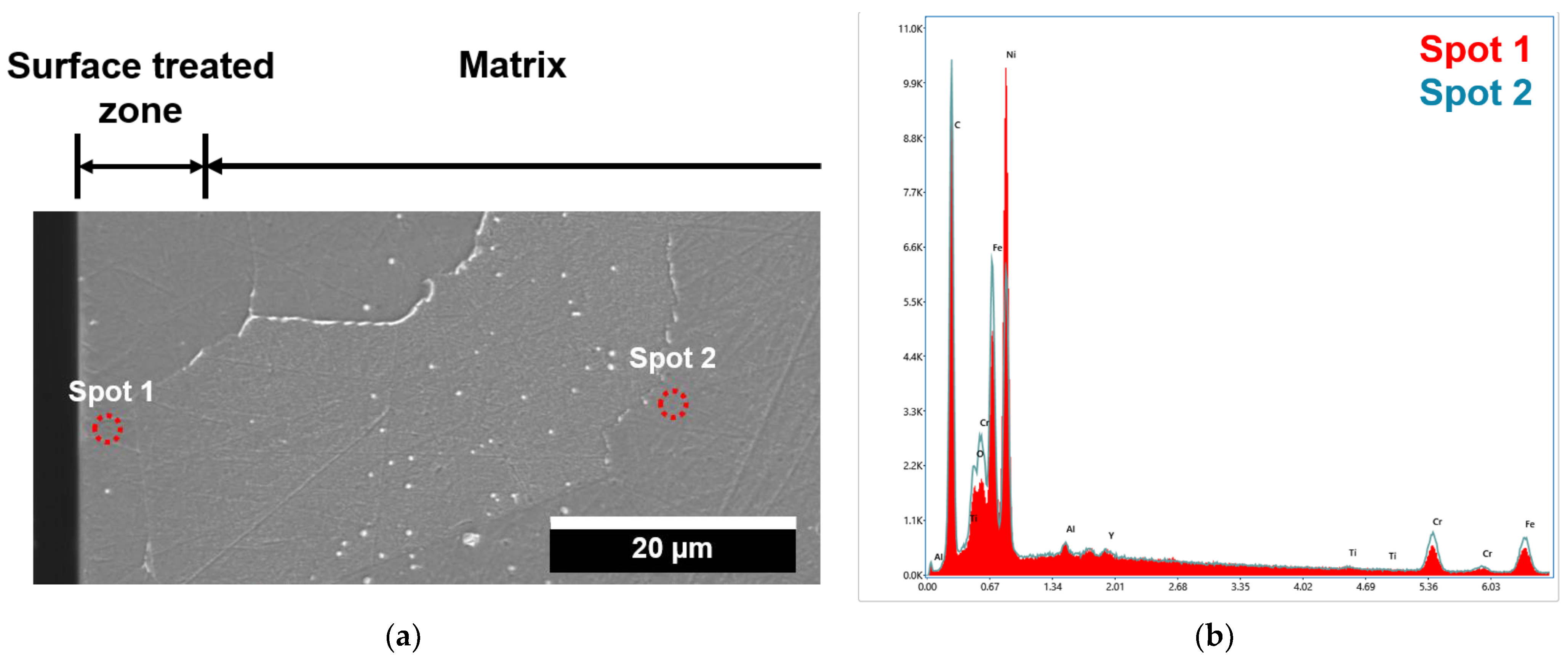
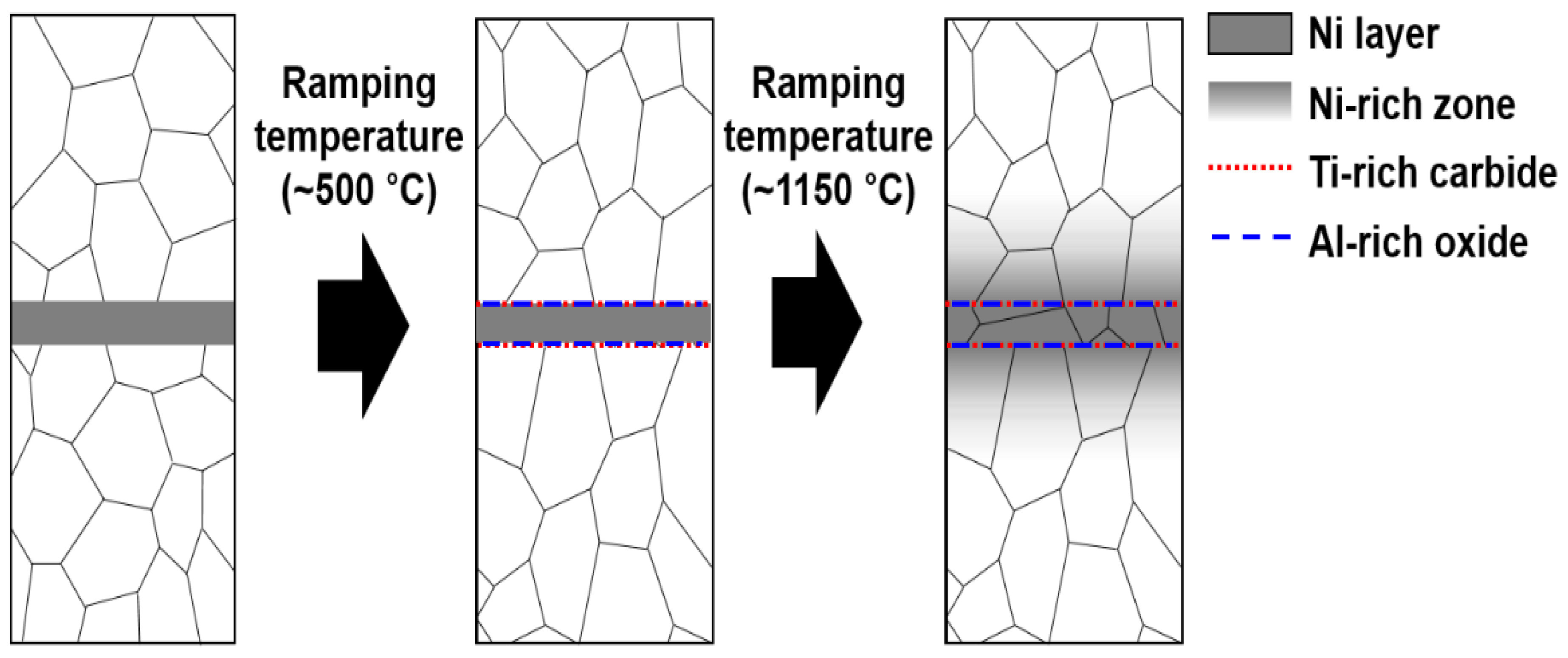
  • The surface treatment of Alloy 800H transformed the chemical composition at/near the surface. The Ni concentration was the maximum at the surface, and the thickness of the surface treated zone was ~10 µm.
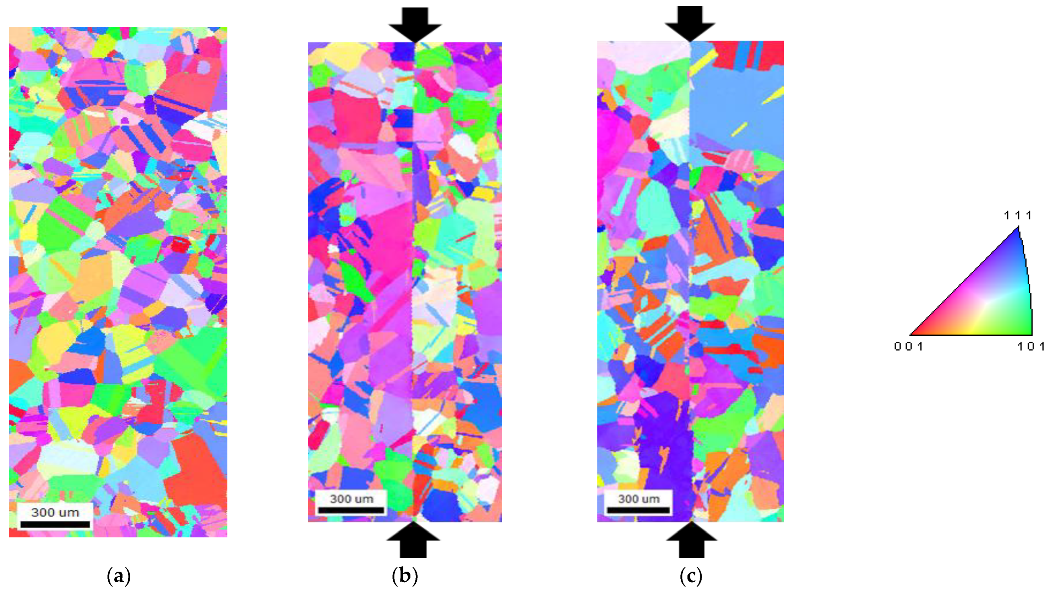
  • The grain boundary bulging at/near the interface occurred due to a reduction of Ti-rich carbides. The sparsely dispersed ~100 nm sized Ti-rich carbides and Al-rich oxides insignificantly influenced the grain boundary bulging across the interface.
  • The chemical compositions of the constitutive elements were homogenized during the diffusion welding process. The chemical compositions at/near the interface satisfied the ASTM specifications.
  • The tensile properties of the diffusion weldment were comparable to those that Alloy 800H underwent with the same thermo-mechanical process up to 700 °C.
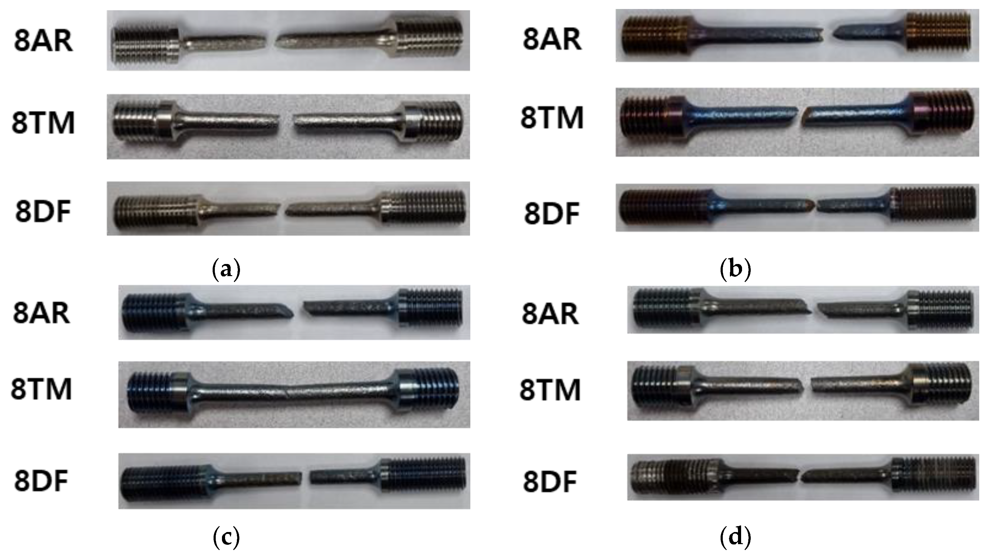
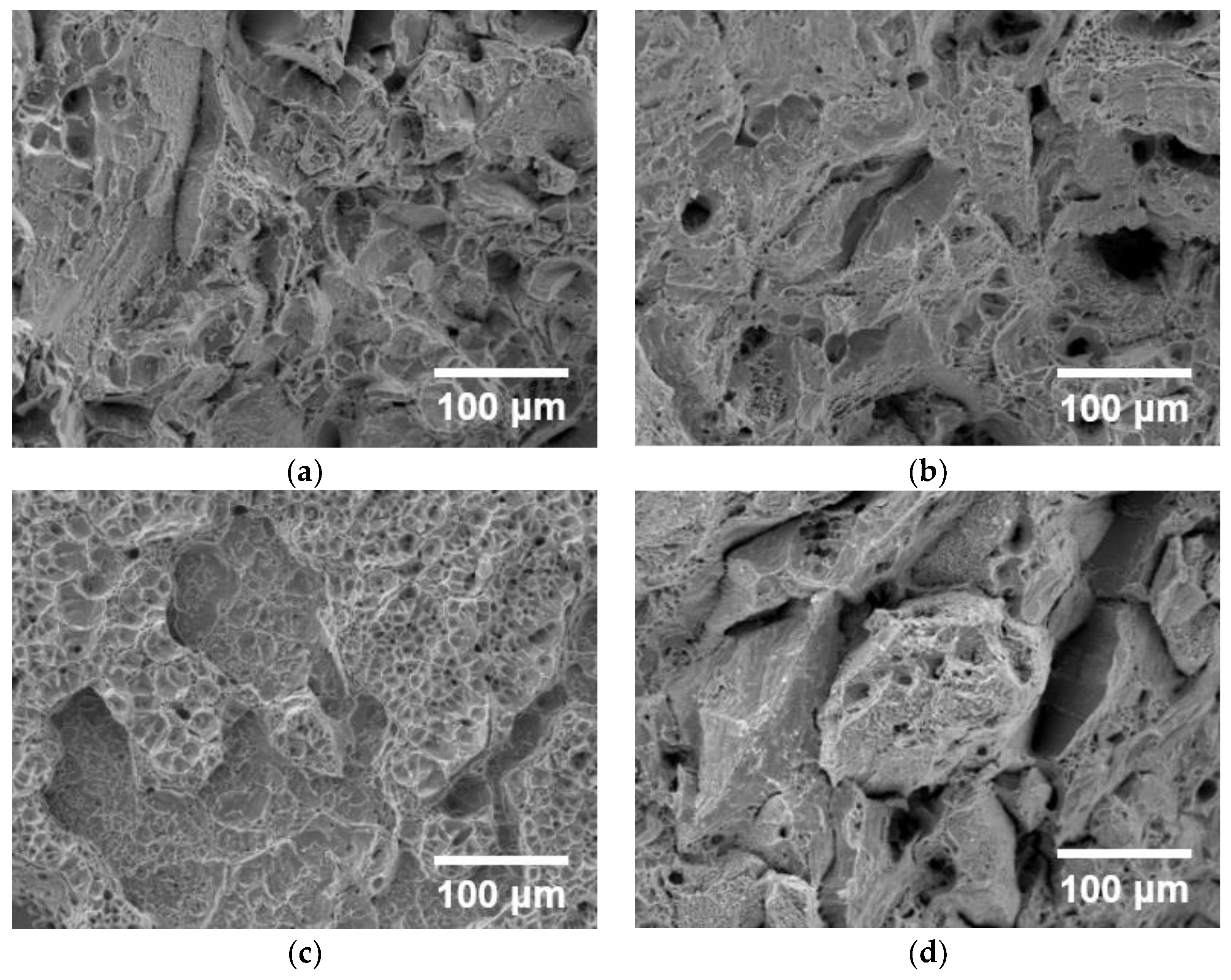
  • The specimens were fractured in a ductile manner. The location of failure was random in the gauge section. Macroscopic deformation was observed on the fracture surface.

6. Patents

A patent titled “Preparing Method for Diffusion Bonding of Alloy and Diffusion Bonding Member Manufactured Using the Preparing Method for Diffusion Bonding of Alloy” was filed by Jong-Bae Hwang, Injin Sa, and Eung-Seon Kim on 5 September 2022, and has been acknowledged by the Korean Intellectual Property Office. The Korea Atomic Energy Research Institute applied for this patent.

Author Contributions

J.-B.H.: conceptualization, methodology, investigation, writing—original draft preparation; I.S., E.-S.K. and D.-H.L.: writing—review and editing; E.-S.K.: funding acquisition. All authors have read and agreed to the published version of the manuscript.

Funding

This research was supported by the Nuclear Research and Development Program of the National Research Foundation of Korea (NRF) grant funded by the Ministry of Science, ICT & Future Planning (2020M2D4A2068407).

Data Availability Statement

Data will be made available on request.

Conflicts of Interest

The authors declare that they have no known competing financial interest or personal relationship that could have appeared to influence the work reported in this paper.

References

  1. Takeda, T.; Kunitomi, K.; Horie, T.; Iwata, K. Feasibility Study on the Applicability of a Diffusion-Welded Compact Intermediate Heat Exchanger to Next-Generation High Temperature Gas-Cooled Reactor. Nucl. Eng. Des. 1997, 168, 11–21. [Google Scholar] [CrossRef]
  2. Clark, D.E.; Mizia, R.E.; Glazoff, M.V.; Sabharwall, P.; McKellar, M.G. Diffusion Welding of Alloys for Molten Salt Service—Status Report; INL/EXT-12-24589 Rev. 1; Idaho National Laboratory: Idaho Falls, ID, USA, 2012. [CrossRef]
  3. Nestell, J.; Sham, T.L. ASME Code Considerations for the Compact Heat Exchanger; ORNL/TM-2015/401; Oak Ridge National Laboratory: Oak Ridge, TN, USA, 2015. [CrossRef]
  4. Ohsumi, M.; Kiyotou, S.I.; Sakamoto, M. The Application of Diffusion Welding to Aircraft Titanium Alloy. Trans. Iron Steel Inst. Japan 1985, 25, 513–520. [Google Scholar] [CrossRef]
  5. Chaturvedi, M.C. (Ed.) Welding and Joining of Aerospace Materials; Woodhead Publishing: Sawston, UK, 2012. [Google Scholar]
  6. Xiong, J.; Peng, Y.; Samiuddin, M.; Yuan, L.; Li, J. Common Mechanical Properties of Diffusion Bonded Joints and Their Corresponding Microstructure Features. J. Mater. Eng. Perform. 2020, 29, 3277–3286. [Google Scholar] [CrossRef]
  7. Sah, I.; Kim, D.; Lee, H.J.; Jang, C. The Recovery of Tensile Ductility in Diffusion-Bonded Ni-base Alloys by Post-Bond Heat Treatments. Mater. Des. 2013, 47, 581–589. [Google Scholar] [CrossRef]
  8. Hong, S.; Kim, S.H.; Jang, C.; Sah, I. The Effect of Post-Bond Heat Treatment on Tensile Property of Diffusion Bonded Austenitic Alloys. Trans. Korean Soc. Mech. Eng. A 2015, 39, 1221–1227. [Google Scholar] [CrossRef]
  9. Sah, I.; Hwang, J.B.; Hong, S.I.; Kim, E.S.; Kim, M.H. Effect of Heat Treatment on the Diffusion-Bonded Ni-Base Alloy Hastelloy X. Korean J. Met. Mater. 2017, 55, 114–123. [Google Scholar] [CrossRef]
  10. Sah, I.; Hwang, J.B.; Kim, W.G.; Kim, E.S.; Kim, M.H. High-Temperature Mechanical Behaviors of Diffusion-Welded Alloy 617. Nucl. Eng. Des. 2020, 364, 110617. [Google Scholar] [CrossRef]
  11. Mizia, R.E.; Clark, D.E.; Glazoff, M.V.; Lister, T.E.; Trowbridge, T.L. Progress Report for Diffusion Welding of the NGNP Process Application Heat Exchangers; INL/EXT-11-21817 Revision 1; Idaho National Laboratory: Idaho Falls, ID, USA, 2011. [CrossRef]
  12. Mizia, R.E.; Clark, D.E.; Glazoff, M.V.; Lister, T.E.; Trowbridge, T.L. Optimizing the Diffusion Welding Process for Alloy 800H: Thermodynamic, Diffusion Modeling, and Experimental Work. Metall. Mater. Trans. A 2013, 44, 154–161. [Google Scholar] [CrossRef]
  13. Mahajan, H.P.; Elbakhshwan, M.; Beihoff, B.C.; Hassan, T. Mechanical and Microstructural Characterization of Diffusion Bonded 800H. In Proceedings of the Pressure Vessels and Piping Conference, Online, 3 August 2020. [Google Scholar] [CrossRef]
  14. An, T.; Subramanian, G.O.; Jang, C. Effect of Post-Bond Heat Treatment on the Diffusion Bonding Properties of Alloy 800H with Ni-Foil Interlayer. In Proceedings of the Transactions of the Korean Nuclear Society Virtual Autumn Meeting, Online, 21–22 October 2021; Available online: https://www.kns.org/files/pre_paper/46/21A-138-%EC%95%88%ED%83%9C%EC%A0%95 (accessed on 21 October 2021).
  15. Mahajan, H.P.; Lima, L.M.A.; Hassan, T. Mechanical and Microstructural Performance Evaluation of Diffusion Bonded Alloy 800H for Very High Temperature Nuclear Service. J. Eng. Mater. Technol. 2022, 144, 021008. [Google Scholar] [CrossRef]
  16. Rozman, K.A.; Carl, M.A.; Kapoor, M.; Doğan, Ö.N.; Hawk, J.A. Creep Performance of Transient Liquid Phase Bonded Haynes 230 Alloy. Mater. Sci. Eng. A 2019, 768, 138477. [Google Scholar] [CrossRef]
  17. Malekan, A.; Farvizi, M.; Mirsalehi, S.E.; Saito, N.; Nakashima, K. Holding Time Influence on Creep Behavior of Transient Liquid Phase Bonded Joints of Hastelloy X. Mater. Sci. Eng. A 2020, 772, 138694. [Google Scholar] [CrossRef]
  18. Hu, M.; Li, C.; Guo, Q.; Han, X.; Ding, R.; Li, H.; Xia, X.; Liu, Y. Improving Creep Property and Deformation Mechanism of Transient Liquid Phase Bonded Polycrystalline Ni3Al-Based Superalloy with Post Bond Heat Treatment. Mater. Sci. Eng. A 2023, 874, 145078. [Google Scholar] [CrossRef]
  19. Sah, I.; Kim, E.S. Enhanced Joint Integrity of Diffusion-Welded Alloy 617 by Controlling the Micro-Chemistry near the Surface. Mater. Today Commun. 2021, 29, 102770. [Google Scholar] [CrossRef]
  20. Lei, X.W.; Li, D.Y.; Zhang, X.H.; Liang, T.X. Effect of Solid Solution Elements on Solubility Products of Carbides and Nitrides in Austenite: Thermodynamic Calculations. Metall. Mater. Trans. A 2019, 50, 4445–4461. [Google Scholar] [CrossRef]
  21. ASTM B409-22; Standard Specification for Nickel-Iron-Chromium Alloy Plate, Sheet, and Strip. ASTM International: West Conshohocken, PA, USA, 2022.
  22. ASTM E8/E8M-22; Standard Test Methods for Tension Testing of Metallic Materials. ASTM International: West Conshohocken, PA, USA, 2022.
  23. ASTM E21-20; Standard Test Methods for Elevated Temperature Tension Tests of Metallic Materials. ASTM International: West Conshohocken, PA, USA, 2021.
  24. Bassford, T.H.; Hosier, J.C. Production and Welding Technology of Some High-Temperature Nickel Alloys in Relation to Their Properties. Nucl. Technol. 1984, 66, 35–43. [Google Scholar] [CrossRef]
  25. Wright, J.K.; Carroll, L.J.; Cabet, C.; Lillo, T.M.; Benz, J.K.; Simpson, J.A.; Lloyd, W.R.; Chapman, J.A.; Wright, R.N. Characterization of Elevated Temperature Properties of Heat Exchanger and Steam Generator Alloys. Nucl. Eng. Des. 2012, 251, 252–260. [Google Scholar] [CrossRef]
  26. Wright, J.K.; Simpson, J.A.; Wright, R.N.; Carroll, L.J.; Sham, T.L. Strain Rate Sensitivity of Alloys 800H and 617. In Proceedings of the ASME 2013 Pressure Vessels and Piping Conference, Paris, France, 14–18 July 2013. [Google Scholar] [CrossRef]
  27. Cao, Y.; Zhang, C.; Zhang, C.; Di, H.; Huang, G.; Liu, Q. Influence of Dynamic Strain Aging on the Mechanical Properties and Microstructural Evolution for Alloy 800H during Hot Deformation. Mater. Sci. Eng. A 2018, 724, 37–44. [Google Scholar] [CrossRef]
  28. Broek, D. A Study on Ductile Fracture; NLR–TR 71021 U; National Aerospace Laboratory NLR: Amsterdam, The Netherlands, 1971. [Google Scholar]
  29. Wada, T.; Wada, H.; Elliott, J.F.; Chipman, J. Thermodynamics of the Fcc Fe-Ni-C and Ni-C Alloys. Metall. Mater. Trans. B 1971, 2, 2199–2208. [Google Scholar] [CrossRef]
  30. Rahmel, A.; Grabke, H.J.; Steinkusch, W. Carburization—Introductory survey. Mater. Corros. 1998, 49, 221–225. [Google Scholar] [CrossRef]
  31. Elrefaie, F.A.; Smeltzer, W.W. Thermodynamics of Nickel-Aluminum-Oxygen System between 900 and 1400 K. J. Electrochem. Soc. 1981, 128, 2237–2242. [Google Scholar] [CrossRef]
  32. Young, D.J. High Temperature Oxidation and Corrosion of Metals; Elsevier: Amsterdam, The Netherlands, 2008. [Google Scholar]
  33. Keown, S.R.; Pickering, F.B. Niobium in Stainless Steels. In Proceedings of the Niobium International Symposium, San Francisco, CA, USA, 8–11 November 1981. [Google Scholar]
  34. Kajihara, M.; Yoshikawa, T.; Kikuchi, M.; Yamauchi, K. Solubility of NbC in a Ni-16Cr-8Fe alloy. ISIJ Int. 1992, 32, 755–763. [Google Scholar] [CrossRef]
  35. Vander Voort, G.F. (Ed.) Atlas of Time-Temperature Diagrams for Nonferrous Alloys; ASM International: Tokyo, Japan, 1991. [Google Scholar]
  36. Neumann, G.; Tuijn, C. Self-Diffusion and Impurity Diffusion in Pure Metals: Handbook of Experimental Data; Elsevier: Amsterdam, The Netherlands, 2017. [Google Scholar]
  37. Lander, J.J.; Kern, H.E.; Beach, A.L. Solubility and Diffusion Coefficient of Carbon in Nickel: Reaction Rates of Nickel-Carbon Alloys with Barium Oxide. J. Appl. Phys. 1952, 23, 1305–1309. [Google Scholar] [CrossRef]
Figure 1. Schematic of the diffusion welding process.
Metals 13 01727 g001
Figure 2. EDS point analysis near the surface and matrix: (a) cross-section image of surface treated Alloy 800H and (b) EDS spectra from spot 1 and 2.
Metals 13 01727 g002
Figure 3. Line profile of surface treated Alloy 800H: (a) results for Fe, Ni, and Cr, and (b) results for Al and Ti.
Metals 13 01727 g003
Figure 4. EBSD analysis at/near the interface: (a) as-received, (b) 8NP0, and (c) 8NP2.
Metals 13 01727 g004
Figure 5. TEM/EDS analysis for determining the secondary precipitates at/near the interface of 8NP0.
Metals 13 01727 g005
Figure 6. Chemical compositions at/near the interface: (a) as-received, (b), 8NP0, and (c) 8NP2.
Metals 13 01727 g006
Figure 7. Stress−strain curves of the diffusion-welded Alloy 800H at 25 °C for examining the validity of the newly developed method.
Metals 13 01727 g007
Figure 8. Stress–strain curves of the diffusion-welded Alloy 800H. Tensile tests were performed at: (a) 25 °C, (b) 540 °C, (c) 650 °C, (d) 700 °C.
Metals 13 01727 g008
Figure 9. Photographs of the fractured tensile specimens. Tensile tests were performed at: (a) 25 °C, (b) 540 °C, (c) 650 °C, (d) 700 °C. The interface is located at the center of the gauge section.
Metals 13 01727 g009
Figure 10. SEM micrographs showing the fracture surfaces. Tensile tests were performed at: (a) 25 °C, (b) 540 °C, (c) 650 °C, (d) 700 °C.
Metals 13 01727 g010
Figure 11. Schematic of diffusion welding of heat-resistant alloys with a Ni interlayer.
Metals 13 01727 g011
Table 1. Chemical compositions of Alloy 800H.
DesignationChemical Compositions [wt.%]
FeNiCrAlCMnSiSTiCuPRemark
UNS N0881039.5
min
30
min
19.0
min
0.15
min
0.05–0.101.5
max
1.00.0150.15–0.600.75--
800H(T)
(HH2768AG)
45.7931.8520.120.490.070.870.170.0010.580.120.013Al + Ti = 1.00
800H
(735400)
46.8330.1820.430.490.070.980.420.0000.540.450.022Al + Ti = 1.03
Table 2. Diffusion welding conditions.
AlloyDesignationDimension
[mm]
QtyTemperature
[°C]
Pressure
[MPa]
Time
[min]
Vacuum
[Torr]
Avg. ΔZ
[%]
Post-Weld Heat TreatmentRemark
800H(T)
(HH2768AG)
8NP050 (L) × 50 (W) × 25 (T)2115010607.0 × 10−5−2.91-Microstructure, tensile
8NP2-1120 °C
20 h
Tensile
800H
(735400)
8NB110 (L) × 80 (W) × 25 (T)4114071207.0 × 10−5−0.921120 °C
20 h
Tensile
Table 3. Mechanical properties of the diffusion-welded Alloy 800H.
Temperature (°C)DesignationYield Strength (YS, MPa)Tensile Strength (MPa)Elongation (%)
258AR23956350.4
8TM20155544.9
8DF20255346.7
5408AR14848753.6
8TM12245444.5
8DF12045046.6
6508AR14241842.7
8TM11837240.9
8DF11237639.1
7008AR14136237.8
8TM11229940.2
8DF11131237.3
Table 4. Comparison of niobium carbide precipitation in a Fe-Cr matrix and a Ni-Cr matrix (NNb = 0.58 wt.% for reaction quotient) [30,31].
NC
(wt.%)
Matrix
Fe-Cr (Fe-25Ni-20Cr)
log[(Nb)(C)] = 4.07 − 8358/T
Ni-Cr (Alloy 600)
ln[(Nb)(C0.81)] = 7.5 − 14000/T
Solubility ProductReaction QuotientNNb, min
(wt.%)
Solubility ProductReaction QuotientNNb, min
(wt.%)
0.070.0150.0400.130.0960.0690.83
0.140.0810.0770.120.47
Disclaimer/Publisher’s Note: The statements, opinions and data contained in all publications are solely those of the individual author(s) and contributor(s) and not of MDPI and/or the editor(s). MDPI and/or the editor(s) disclaim responsibility for any injury to people or property resulting from any ideas, methods, instructions or products referred to in the content.

