Article

Dynamic Tensile Behavior of Laser-Directed Energy Deposition and Additive Friction Stir-Deposited AerMet 100

1
US Army Engineer Research and Development Center, Vicksburg, MS 39180, USA
2
Department of Mechanical Engineering, Mississippi State University, Starkville, MS 39762, USA
3
General Electric Aerospace, Cincinnati, OH 45215, USA
*
Author to whom correspondence should be addressed.
Metals 2023, 13(10), 1736; https://doi.org/10.3390/met13101736
Submission received: 28 August 2023 / Revised: 3 October 2023 / Accepted: 9 October 2023 / Published: 13 October 2023

Abstract

:
Quasi-static and high-rate tensile experiments were used to examine the strain rate sensitivity of laser-directed energy deposition (L-DED)- and additive friction stir deposition (AFSD)-formed AerMet 100 ultrahigh-strength steel-additive manufactured builds. Electron backscattered diffraction (EBSD) revealed similar as-deposited grain sizes between the two AM processes at approximately 24 μm and 17 μm for the L-DED and AFSD samples, respectively. The strain hardening rate, θ, revealed little change in the overall hardening observed in the L-DED and AFSD materials, with a consistent hardening in the quasi-static samples and three identifiable regions in that of the high-rate tested materials. The L-DED deposited materials displayed average ultimate tensile strength values of 1835 and 2902 MPa for the 0.001 s−1 and 2500 s−1 strain rates, respectively and the AFSD deposited materials displayed ultimate tensile strength values of 1928 and 3080 MPa for the 0.001 s−1 and 2500 s−1 strain rates, respectively. Overall, the strength for both processes displayed a positive strain rate sensitivity, with increases in strength of ~1000 MPa for both processes. Fractography revealed significant solidification voids in the laser DED material and poor layer adhesion in the AFSD material.

1. Introduction

As the need for high mechanical performance and simultaneous weight reduction increases, parts are more often being designed as single components. Combining these parts into one complex geometry has begun to expose the limitations of traditional manufacturing techniques such as extrusion, forging, casting, and computer numerical control (CNC) machining. Additive manufacturing (AM), otherwise known as 3D printing, is a layer-by-layer manufacturing processes that has been identified as a key element in the fourth industrial revolution [1,2]. According to ISO/ASTM 52900:2021, Additive Manufacturing—General Principles—Fundamentals and Vocabulary, there are seven techniques to generate the layers in AM, including binder jetting (BJT), directed energy deposition (DED), material extrusion (MEX), material jetting (MJT), powder bed fusion (PBF), sheet lamination (SHL), and vat photopolymerization (VPP) [3].
Laser-directed energy deposition (L-DED), similar to laser cladding, uses a high-intensity energy source to create a melt pool from either powder or wire feedstock that travels along the build path to deposit material [4,5,6]. The process creates a metallurgical bond between the substrate and deposited material with minimal dilution and distortion, making it an ideal technique for repair. Other advantages of L-DED include controlled heat input, great process flexibility, and high dimensional accuracy [7,8,9,10].
Additive friction stir deposition (AFSD) is a solid-state process that consist of a rotating hollow tool which material, in the form of powder or solid rod, is fed through. During rotation of the tool, the deposition material interacts with the substrate and tool and is then softened due to the heat generation from the frictional forces [11,12,13,14]. Transverse motion of the tool then results in the deposition of a track of material that is typically several hundreds of microns thick. A schematic of the AFSD process can be reviewed in Figure 1. Unlike some L-DED and laser-powder-bed-fusion (L-PBF) processes, AFSD is considered a near-net-shape process and traditionally requires post-machining to achieve final part geometry. However, AFSD materials are typically fully dense, do not suffer from solidification defects, and can exhibit properties on par with wrought materials in the as-deposited state without further heat treating [15]. Post deposition heat treatments can be required for precipitation-hardened alloys, like some aluminum alloys, to return the properties to the wrought performance, however.
Ultrahigh-strength steel (UHSS) is a class of structural steels with a yield strength above 1350 MPa [16]. AerMet 100, 23Co14Ni11Cr3Mo, is an ultrahigh-strength steel with the great combination of high fracture toughness, high strength, and corrosion resistance that make it a potential replacement for high-strength low-alloy (HSLA) steels such as AISI4340 and 300 M [17]. Generally, it is used in a slightly overaged condition from being tempered at 482 °C for 5 h. The developed microstructure then consists of Fe-Ni martensitic laths, reverted austenite, and M2C carbides, with a resulting yield strength of 1690 MPa [18,19,20]. Currently, AerMet 100 is leveraged in a variety of applications including landing gears, actuators, ordnance and jet engine shafts [21]. Many of these applications operate in the high-rate regime; however, little work has been performed to better understand the strain-rate sensitivity and high-rate mechanical performance of the material at strain rates above 500 s−1. Early work, performed by Reinhart et al., focused on the utilization of gas-gun evaluation to study yield stress and spall strength in AerMet 100, and Boyce et al. and Hu et al. studied the use of a split-Hopkinson pressure bar (SHPB) to determine the mechanical performance of AerMet 100 at 200 s−1 and 500 s−1, respectively [22,23,24].
The conventional manufacturing process of AerMet 100 components includes first vacuum arc melting (VAR) and then a homogenization heat treatment to eliminate microsegregation. The material is then subjected to hot forging to form the material into the intended part geometry and decreasing the grain size through recrystallization. These processes can be costly and require multiple iterations and post machining. With high production costs and long lead times through traditional manufacturing, AM can be a great alternative to produce final part geometries of ultrahigh-strength material systems. The resulting microstructural and mechanical performance of AerMet 100 deposited through L-DED and wire arc additive manufacturing (WAAM) have been studied previously along with L-PBF [8,25,26,27,28,29]. Currently, no work has been performed to better understand how AFSD may change the deposited material system and the AerMet 100 strain-rate dependence.
To bridge the knowledge gaps in the strain-rate sensitivity and additive manufacturing of AerMet100, the current work examines the deposition of an AerMet 100 steel using L-DED and AFSD to better understand the mechanical performance and the difference in strain-rate dependance of the resulting material. The resulting materials were studied in tension at quasi-static (0.001 s−1) and high rate (2500 s−1) strain rates. Subsequently, the strain hardening rate, θ, was analyzed and compared between the two deposition processes and strain rates. Fractography was also used to better understand the failure mechanisms present for the two AM-processed materials.

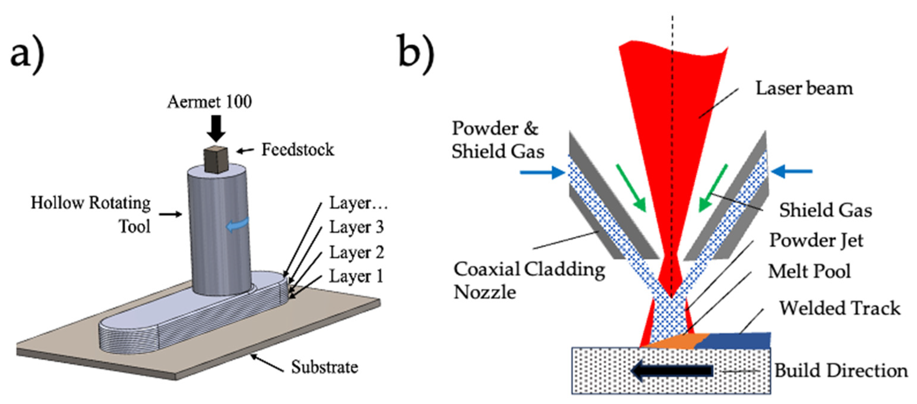
2. Materials and Methods

AerMet 100 (nominal composition of 0.21–0.25 C, 11–12 Ni, 13–14 Co, 2.9–3.3 Cr, 1.1–1.3 Mo balance Fe) was deposited on an A36 steel substrate with dimensions of 305 × 305 × 13 mm using both L-DED and AFSD. The AFSD feedstock material was machined into 9.525 mm square rectangular rods. Before deposition with AFSD, a graphite aerosol lubricant was applied to the feedstock to avoid jamming in the deposition tool. After feedstock coating, a commercially available L3 AFSD machine (MELD Manufacturing, Christiansburg, VA, USA) was used to deposit the AerMet 100 barstock material on an A36 steel substrate in a noncontinuous layer-by-layer approach, as seen in Figure 1. The feedstock rods were deposited with a tungsten tool and a 5 mm layer height. The build parameters for AerMet 100 deposition were as follows: a spindle rotation speed of 500 rpm, traversing speed of 205.74 mm/min, and actuator feed rate of 21.08 mm/min.
Laser DED was also used to deposit powder AerMet 100 onto an A36 steel substrate with dimensions of 304.8 × 304.8 × 12.7 mm. During the deposition process, the substrate plate was tilted at an angle of 15° to reduce back reflection into the deposition head. A Fraunhofer Coax 8 cladding head was controlled by a Kuka KR90 robotic arm to deposit the powder at a laser power of 1200 watts, travel speed of 1.2 m/min, beam spot diameter of 3 mm, and a powder feed rate of 9.5 (g/min).
Both the AFSD and L-DED process used a 0°, 90° scan pattern to eliminate asymmetry seen in the deposited materials between the longitudinal and transverse directions. After deposition, mechanical test specimens were machined from the as-deposited material via a Mitsubishi MV1200 wire EDM. Specimens were machined to the same dimensions for both quasi-static and high-rate testing and utilized a gauge length of 4.5 mm, width of 2 mm, and thickness of 1.5 mm [11].
To better understand the process–structure–property performance relationships of the AerMet 100 subjected to the two additive processes, mechanical testing in tension was performed in triplicate in the quasi-static and high-rate regimes. High-rate analysis was performed in ambient laboratory conditions using a SHPB system made of 350 maraging steel and a striker with a 12.7 mm diameter, as depicted in Figure 2. The SHPB experiments were performed at a strain rate of ~2500 s−1 in tension, and data were gathered through an oscilloscope using semiconductor strain gauges placed on the bar and a Matlab subroutine to process the stress–strain behavior and stress equilibrium during testing [30]. A pulse shaper was used at the interface between the striker and bar to facilitate stress equilibrium and constant strain-rate deformation. The pulse shaper of 5 mm thick and 6 mm diameter allowed the profile of the incident wave to be modified in relation to the specimen response. Representative input signals and strain rate plots are depicted in Figure 3. Quasi-static samples were also tested in ambient conditions using a 25 kN Landmark 370 MTS servo hydraulic load frame at a strain rate of 0.001 s−1.
A FEI Nova NanoSEM 620 equipped with a Bruker electron backscattered diffraction (EBSD) system was used to gather microstructural images and grain orientation data at three locations for the two additive conditions, as well as perform the fractography of the mechanical test specimens for both the AFSD and DED materials. Samples for metallography were prepared by mechanical polishing to 1200 grit using SiC paper and then electrolytically polished using a solution of Struers A2 electrolyte for 30 s at a voltage of 14 mV.
Microhardness measurements were performed on a Struers Durascan hardness tester. Indentation lines were performed using a Vickers indenter and a 0.2 kg load with a 0.5 mm indent spacing running through the deposited material, across the deposition/substrate interface, and into the substrate at three different locations. The data were then plotted to better understand the overall hardness of the deposition for AFSD and DED, as well as the changes to the interface region and heat-affected zones.

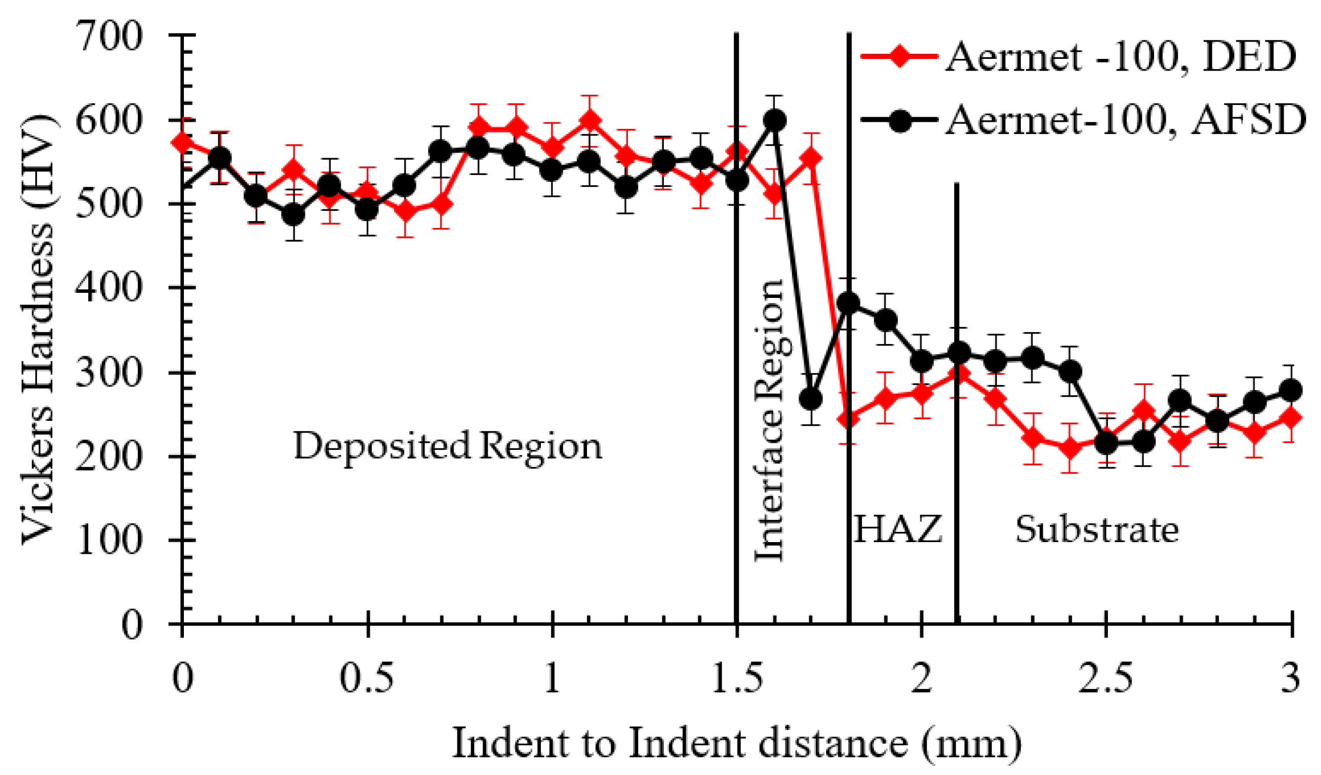
3. Results and Discussion

EBSD, normal to the deposition direction, was used to better understand the microstructure of the as-deposited L-DED and AFSD material, and the results of this can be observed in Figure 4. The L-DED material exhibited a typical microstructure of the material, with a high amount of martensite present and an average grain size of 24 μm. L-DED produces high cooling rates of the solidification structure between 103 and 106 °C/s and typically sees a dominant martensitic microstructure. The Fe-Ni lath martensitic structure is formed during the rapid cooling of austenite [31].
The AFSD material exhibited a more uniform martensitic microstructure than that of the L-DED material and exhibited a smaller grain size of 17 μm. Overall, the cooling rates were likely not as high in the AFSD process due to the material maintaining a solid state during deposition.
The L-DED material hardness was observed to be 521 HV during the first half of the deposited region depicted in Figure 5. However, the hardness was seen to rise by ~5% closer to the substrate before significantly falling due to the weaker strength of the substrate material. The increased hardness could be due to the coarsening of the microstructure caused by the repeated passes and the unpinning of austenite grain boundaries at high temperatures. A similar behavior was seen in the AFSD material. However, the HAZ of the AFSD substrate displayed a significantly higher hardness than that of the L-DED. Similar hardness profiles for a laser-clad AerMet 100 were observed by Aditya et al., with a hardness range of 500 to 520 HV [28]. Likewise, Ran et al. reported hardness values ranging from 445 to 536 HV depending on location in an L-DED tower build [26]. Chou et al. studied the use of AFSD to deposit AerMet 100 on a 1080 steel through microhardness indentation. The study utilized AFSD to perform repairs of machined grooves in plate material. The effort observed peak Vickers hardness values of 825 and minimum values of 364 HV depending on the processing conditions and number of passes over the defect. Wrought AerMet 100 has a minimum hardness of 600 HV, exceeding that of the deposited material. However, the work by Aditya et al. also observed a 100 HV increase in hardness due to a post cladding heat treatment, suggesting potential increases in hardness capable in the current work [28].
Tensile stress–strain results for quasi-static (0.001 s−1) and high-rate (2500 s−1) can be seen in Figure 6. The quasi-statically deformed samples exhibited an almost-constant strain hardening throughout deformation, as seen in Figure 6b. Both the L-DED and AFSD materials exhibited the same θ throughout, with no softening observed. However, the strain hardening rate for the high-rate tested materials exhibited three distinct regions: an initial strain hardening, followed by a rapid increase in the overall strain hardening rate, and then a slight softening leading to failure. Both the AFSD and L-DED materials exhibited similar trends, with the strain hardening rate of the AFSD material being more drawn out due to the delayed onset of the increased θ. The overall yield strength (YS), ultimate tensile strength (UTS), and elongation to failure (EL) for the L-DED and AFSD materials can be seen in Figure 6c,d, respectively. Figure 6c shows a positive strain rate sensitivity for the L-DED material, with an increase in the yield stress by ~1200 MPa and an increase in UTS of ~1070 MPa. While mechanical performance tests can be found elsewhere for L-DED, the results are limited to the quasi-static regime. Ran et al. reported YS values of 1062 and 1137 MPa for as-deposited L-DED AerMet 100, and Sun et al. reported YS values of ~1009 MPa [25,32]. Figure 6d also displays a positive strain rate sensitivity for the AFSD material, with an increase in YS of ~1200 MPa and an increase in UTS of ~1152 MPa.
Overall, neither the L-DED- nor the AFSD-deposited materials met the specification for wrought AerMet 100 material, as shown in Table 1. However, Ran et al. reported an increase in UTS of ~500 MPa for a laser-clad AerMet 100 subjected to a post deposition heat treatment consisting of a homogenization and then a tempering step. The increase in mechanical properties were attributed to the elimination of cellular segregation. The post-deposition heat treatment samples also exhibited smaller, more dispersed carbides, which in turn increased the strength through dislocation pinning while simultaneously increasing the ductility [26]. Jelis et al., similarly, reported a significant increase in the tensile properties of an L-PBF additively manufactured AerMet 100. Jelis et al. studied the use of a stress relief, and two separate heat treatments. The effort found a reduction in the UTS for all three treatments but an overall increase in YS ranging from ~200 to 600 MPa [33]. In regard to the strength of the materials deposited by the two processes in the present study, the AFSD material displayed a slightly higher average UTS than that of the L-DED. However, the L-DED material displayed a higher YS. By comparison, Lu et al. reported an average YS and UTS of ~1232 and ~1903 MPa, respectively, for a WAAM-deposited AerMet 100 with an in situ micro rolling technique [27]. The effort observed the main grain refinement mechanism in the as-deposited samples was austenization. The material exhibited benefits from small layer heights and appropriately large heat inputs to help aid in the grain refinement. The effort also observed a significant increase in both the tensile properties and KIc values when the deposited material was subjected to a homogenization heat treatment. The homogenization heat treatment was observed to alleviate cellular segregation and achieved the increased combination of mechanical properties [27]. These findings further elucidate the need for the thermal treatment of both the AFSD and L-DED materials to increase the mechanical properties.
Fractography images of the failed tensile dogbones can be seen in Figure 7, Figure 8, Figure 9 and Figure 10. The overall failure surface of the L-DED 0.001 s−1 sample can be seen in Figure 7a. Large solidification defects, in the form of voids ranging from ~25 to 70 μm, were present in the material and can be seen in Figure 7b. Fractured particles were also observed at the bottom of void nucleation sites. Both the solidification voids and the particles act as stress risers and nucleation sites for failure, as evidenced by the fractured particle observed in Figure 7c. Unlike processes like LPBF, where gas porosity is mainly caused due to the application of high-energy-density lasers causing the collapse of keyholes, there are many ways for gasses to become entrapped and lead to porosity in L-DED. During most L-DED processes, an inert gas, such as argon or nitrogen, is used as a shielding gas and powder carrier to protect from the oxidation of the molten material. Chouhan et al. observed gas porosities formed at both low and high energy densities due to particle arrestment in the melt pool and the small formation of bubbles. Stagnant melt-pool zones were found to increase the porosity due to the inability of bubbles to escape during the solidification process [34]. The 2500 s−1 tested L-DED material exhibited a similar fracture surface with both large void solidification defects and fractured particles, as observed in Figure 8.
Similarly, the AFSD material also exhibited defects associated with the respective process. The overall fracture surface for the 0.001 s−1 sample displayed delamination at the layer interfaces, and the higher magnification images observed in Figure 9b suggest the layers experienced poor adhesion during deposition. Poor layer adhesion in AFSD is one of the main defects that the near-net-shape process is prone to and can be directly tied to the thermal input characteristics, and can appear as a result of reduced material flow and mixing from a lack of thermal input in the system [35]. On the other extreme, an excess of temperature can cause local melting that leads to porosity and cracks in the build. High shoulder rotation rates or low shoulder transverse speed causes adiabatic heating, leading to an increase in the local temperature over the melt temperature of the material and local melting. Localized melting and the subsequent solidification allows for the nucleation of porosity and cracks [36]. Areas of ductile dimpling as well as cleavage fracture can be observed in different locations of the failure surface, as denoted in Figure 9c. Figure 9d shows a more predominant brittle mechanism observed closer to the layer interfaces, with extensive delamination present. The same behavior was observed in the 2500 s−1 tested material, with an overall brittle failure and delamination between the layer interfaces, as denoted in Figure 10b. Overall, less delamination is present due to the decreased time for void coalescence and growth to occur.

4. Conclusions

To summarize, the influence of increasing tensile strain rate from 0.001 s−1 to 2500 s−1 for an L-DED- and AFSD-deposited AerMet 100 ultrahigh-strength steel was studied for the first time, and the main conclusions are listed as follows:
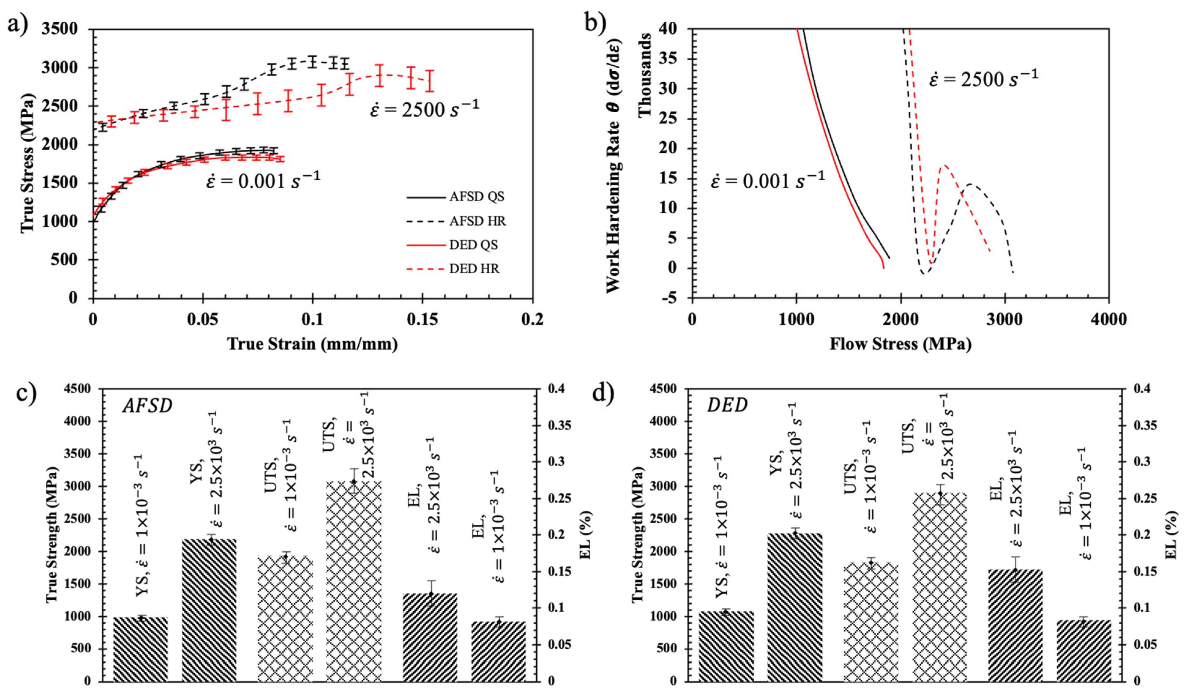
  • The overall microstructure and strain-rate dependance was studied and revealed a positive relationship, with an increasing strain rate for both the L-DED- and AFSD-deposited materials.
  • The L-DED results matched well with those reported in the literature
  • The current work is the first to report on the mechanical performance and strain-rate sensitivity of AFSD AerMet 100.
  • The L-DED-deposited materials displayed average YS and UTS values of 1075, 1835, and 2282, 2902 MPa for the 0.001 s−1 and 2500 s−1 strain rates, respectively.
  • The AFSD-deposited materials displayed YS and UTS values of 982, 1928, and 2189, and 3080 MPa for the 0.001 s−1 and 2500 s−1 strain rates, respectively.
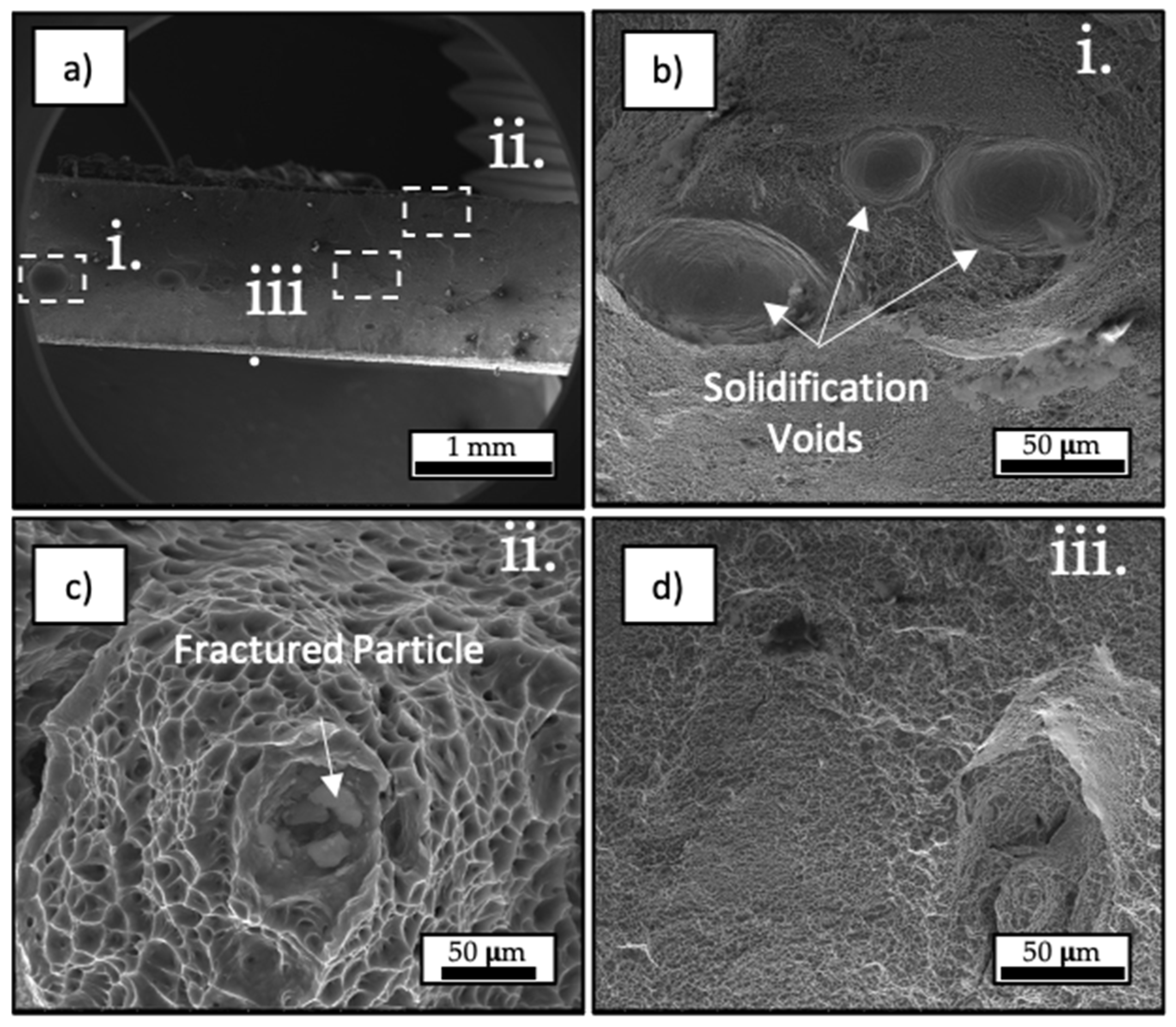
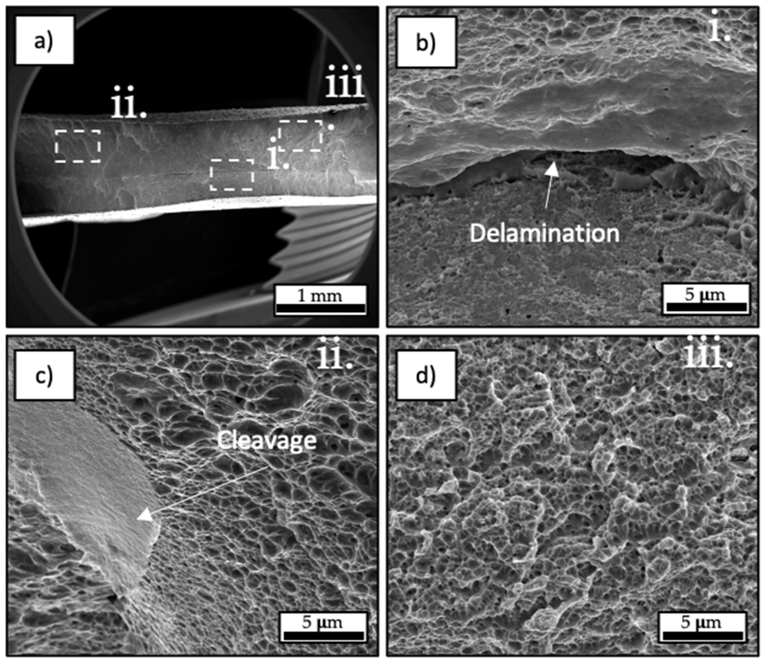
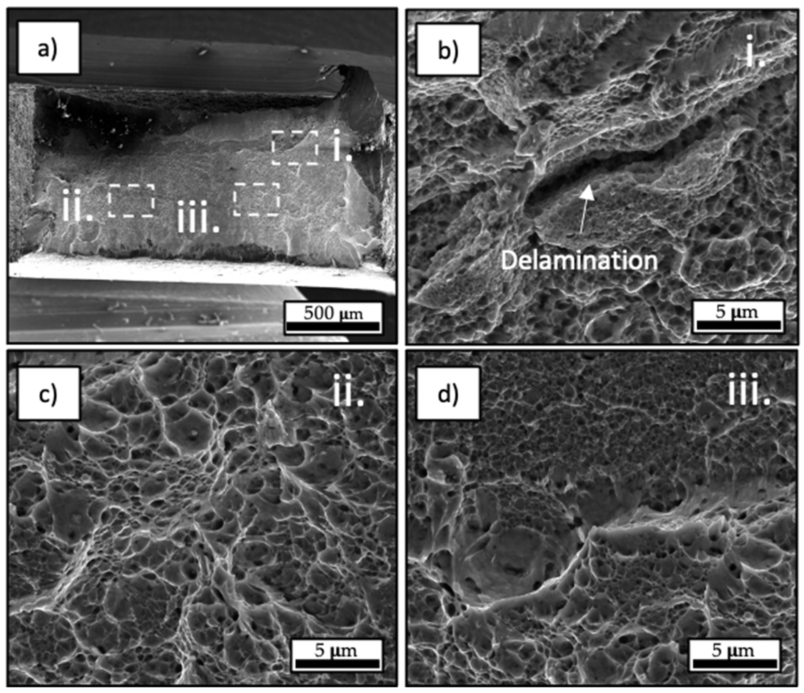
  • Fractography revealed defects associated with the manufacturing process in both the AFSD and L-DED materials, with large solidification voids in the L-DED and delamination from poor layer adhesion in the AFSD.
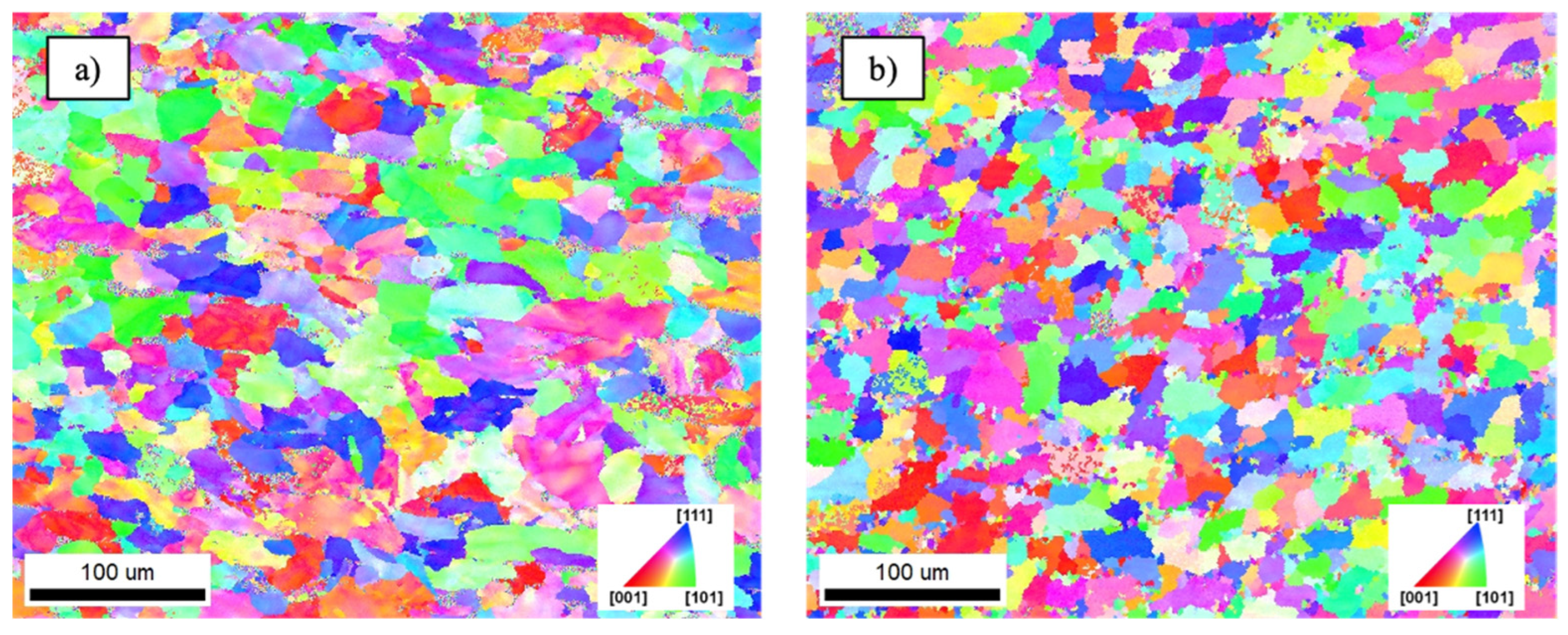
  • Electron backscatter diffraction and scanning electron microscopy revealed a mostly bainitic structure for the L-DED material and a split bainitic and austenitic structure for the AFSD material, with a slightly smaller grain size in the AFSD.
  • Overall, the L-DED- and AFSD-deposited materials exhibited very similar mechanical behaviors with only a difference of 4% at the high rate. However, both the AFSD and the L-DED processes fell short of the wrought AerMet 100 yield strength and ultimate tensile strength specification. Future work investigating the use of a post-deposition heat treatment to increase the mechanical performance is required.
  • Future study of material mechanical properties in the z-direction are also needed to better understand and utilize the different additive manufacturing processes, as well as aid in the calibration of a constitutive model that would be useful in numerical simulations to leverage the technologies.

Author Contributions

Conceptualization, Z.M.; funding acquisition, Z.M.; investigation, Z.M., H.P. and K.D.; methodology, Z.M., H.P. and K.D.; project administration, Z.M.; writing—original draft, Z.M.; writing—review and editing, H.P. and K.D. All authors have read and agreed to the published version of the manuscript.

Funding

The use of trade, product, or firm names in this document is for descriptive purposes only and does not imply endorsement by the U.S. Government. The tests described and the resulting data presented herein, unless otherwise noted, are based on work conducted by the U.S. Army ERDC supported under 500548/AB202 “Protection and Projection Research.” Permission was granted by the Director, Geotechnical and Structures Laboratory to publish this information. The findings of this report are not to be construed as an official Department of the Army position unless so designated by other authorized documents.

Data Availability Statement

The raw and processed data generated during this study will be made available upon reasonable request.

Acknowledgments

The authors thank the following Engineer Research and Development Center (ERDC) personnel for their contributions to this research, i.e., Robert (Cody) Goss and Trevor Robinson for their assistance with specimen preparation, and Christopher Ables for machining components to conduct mechanical experiments. The authors would also like to thank Brady Williams, Baylor University, for aid in mechanical testing.

Conflicts of Interest

The authors declare that they have no known competing financial interests or personal relationships that could have appeared to influence the work reported in this paper.

References

  1. Zheng, P.; Wang, H.; Sang, Z.; Zhong, R.Y.; Liu, Y.; Liu, C.; Mubarok, K.; Yu, S.; Xu, X. Smart Manufacturing Systems for Industry 4.0: Conceptual Framework, Scenarios, and Future Perspectives. Front. Mech. Eng. 2018, 13, 137–150. [Google Scholar] [CrossRef]
  2. Galantucci, L.M.; Guerra, M.G.; Dassisti, M.; Lavecchia, F. Additive Manufacturing: New Trends in the 4th Industrial Revolution. In Proceedings of the 4th International Conference on the Industry 4.0 Model for Advanced Manufacturing, Belgrade, Serbia, 3–6 June 2019; Monostori, L., Majstorovic, V.D., Hu, S.J., Djurdjanovic, D., Eds.; Lecture Notes in Mechanical Engineering. Springer International Publishing: Cham, Switzerland, 2019; pp. 153–169, ISBN 978-3-030-18179-6. [Google Scholar]
  3. ISO/ASTM 52900:2021; Additive Manufacturing—General Principles—Fundamentals and Vocabulary. BSI British Standards: Jersey, UK, 2021.
  4. Jeong, W.; Kwon, Y.-S.; Kim, D. Three-Dimensional Printing of Tungsten Structures by Directed Energy Deposition. Mater. Manuf. Process. 2019, 34, 986–992. [Google Scholar] [CrossRef]
  5. Wang, Y.; Shi, J. Microstructure and Properties of Inconel 718 Fabricated by Directed Energy Deposition with In-Situ Ultrasonic Impact Peening. Metall. Mater. Trans. B 2019, 50, 2815–2827. [Google Scholar] [CrossRef]
  6. Saboori, A.; Biamino, S.; Lombardi, M.; Tusacciu, S.; Busatto, M.; Lai, M.; Fino, P. How the Nozzle Position Affects the Geometry of the Melt Pool in Directed Energy Deposition Process. Powder Metall. 2019, 62, 213–217. [Google Scholar] [CrossRef]
  7. Ganesh, P.; Moitra, A.; Tiwari, P.; Sathyanarayanan, S.; Kumar, H.; Rai, S.K.; Kaul, R.; Paul, C.P.; Prasad, R.C.; Kukreja, L.M. Fracture Behavior of Laser-Clad Joint of Stellite 21 on AISI 316L Stainless Steel. Mater. Sci. Eng. A 2010, 527, 3748–3756. [Google Scholar] [CrossRef]
  8. Sun, S.D.; Liu, Q.; Brandt, M.; Luzin, V.; Cottam, R.; Janardhana, M.; Clark, G. Effect of Laser Clad Repair on the Fatigue Behaviour of Ultra-High Strength AISI 4340 Steel. Mater. Sci. Eng. A 2014, 606, 46–57. [Google Scholar] [CrossRef]
  9. Alam, M.M.; Kaplan, A.F.H.; Tuominen, J.; Vuoristo, P.; Miettinen, J.; Poutala, J.; Näkki, J.; Junkala, J.; Peltola, T.; Barsoum, Z. Analysis of the Stress Raising Action of Flaws in Laser Clad Deposits. Mater. Des. 2013, 46, 328–337. [Google Scholar] [CrossRef]
  10. Hazra, M.; Mondal, A.K.; Kumar, S.; Blawert, C.; Dahotre, N.B. Laser Surface Cladding of MRI 153M Magnesium Alloy with (Al + Al2O3). Surf. Coat. Technol. 2009, 203, 2292–2299. [Google Scholar] [CrossRef]
  11. Rivera, O.G.; Allison, P.G.; Jordon, J.B.; Rodriguez, O.L.; Brewer, L.N.; McClelland, Z.; Whittington, W.R.; Francis, D.; Su, J.; Martens, R.L.; et al. Microstructures and Mechanical Behavior of Inconel 625 Fabricated by Solid-State Additive Manufacturing. Mater. Sci. Eng. A 2017, 694, 1–9. [Google Scholar] [CrossRef]
  12. Rutherford, B.A.; Avery, D.Z.; Phillips, B.J.; Rao, H.M.; Doherty, K.J.; Allison, P.G.; Brewer, L.N.; Jordon, J.B. Effect of Thermomechanical Processing on Fatigue Behavior in Solid-State Additive Manufacturing of Al-Mg-Si Alloy. Metals 2020, 10, 947. [Google Scholar] [CrossRef]
  13. Phillips, B.J.; Avery, D.Z.; Liu, T.; Rodriguez, O.L.; Mason, C.J.T.; Jordon, J.B.; Brewer, L.N.; Allison, P.G. Microstructure-Deformation Relationship of Additive Friction Stir-Deposition Al–Mg–Si. Materialia 2019, 7, 100387. [Google Scholar] [CrossRef]
  14. Avery, D.Z.; Phillips, B.J.; Mason, C.J.T.; Palermo, M.; Williams, M.B.; Cleek, C.; Rodriguez, O.L.; Allison, P.G.; Jordon, J.B. Influence of Grain Refinement and Microstructure on Fatigue Behavior for Solid-State Additively Manufactured Al-Zn-Mg-Cu Alloy. Metall. Mater. Trans. A 2020, 51, 2778–2795. [Google Scholar] [CrossRef]
  15. Gopan, V.; Leo Dev Wins, K.; Surendran, A. Innovative Potential of Additive Friction Stir Deposition among Current Laser Based Metal Additive Manufacturing Processes: A Review. CIRP J. Manuf. Sci. Technol. 2021, 32, 228–248. [Google Scholar] [CrossRef]
  16. Garrison, W.M. Ultrahigh-Strength Steels for Aerospace Applications. JOM 1990, 42, 20–24. [Google Scholar] [CrossRef]
  17. Yoo, C.H.; Lee, H.M.; Chan, J.W.; Morris, J.W. M2C Precipitates in Isothermal Tempering of High Co-Ni Secondary Hardening Steel. Metall. Mater. Trans. A 1996, 27, 3466–3472. [Google Scholar] [CrossRef]
  18. Ayer, R.; Machmeier, P.M. Microstructural Basis for the Effect of Chromium on the Strength and Toughness of AF1410-Based High Performance Steels. Metall. Mater. Trans. A 1996, 27, 2510–2517. [Google Scholar] [CrossRef]
  19. Ayer, R.; Machmeier, P.M. Transmission Electron Microscopy Examination of Hardening and Toughening Phenomena in Aermet 100. Metall. Mater. Trans. A 1993, 24, 1943–1955. [Google Scholar] [CrossRef]
  20. Ayer, R.; Machmeier, P. On the Characteristics of M2C Carbides in the Peak Hardening Regime of AerMet 100 Steel. Metall. Mater. Trans. A 1998, 29, 903–905. [Google Scholar] [CrossRef]
  21. Ran, X.; Zhang, S.; Liu, D.; Tang, H.; Wang, H. Role of Microstructural Characteristics in Combination of Strength and Fracture Toughness of Laser Additively Manufactured Ultrahigh-Strength AerMet100 Steel. Metall. Mater. Trans. A 2021, 52, 1248–1259. [Google Scholar] [CrossRef]
  22. Reinhart, W.D. Dynamic Yield Strength and Spall Strength Determination for AerMet® 100 Steels. In Proceedings of the AIP Conference Proceedings; AIP: Snowbird, UT, USA, 2000; Volume 505, pp. 471–474. [Google Scholar]
  23. Boyce, B.L.; Dilmore, M.F. The Dynamic Tensile Behavior of Tough, Ultrahigh-Strength Steels at Strain-Rates from 0.0002s−1 to 200s−1. Int. J. Impact Eng. 2009, 36, 263–271. [Google Scholar] [CrossRef]
  24. Hu, D.Y.; Meng, K.P.; Jiang, H.L.; Xu, J.; Liu, R.R. Strain Rate Dependent Constitutive Behavior Investigation of AerMet 100 Steel. Mater. Des. 2015, 87, 759–772. [Google Scholar] [CrossRef]
  25. Ran, X.; Liu, D.; Li, A.; Wang, H.; Tang, H.; Cheng, X. Microstructure Characterization and Mechanical Behavior of Laser Additive Manufactured Ultrahigh-Strength AerMet100 Steel. Mater. Sci. Eng. A 2016, 663, 69–77. [Google Scholar] [CrossRef]
  26. Ran, X.; Liu, D.; Li, J.; Liu, X.; Wang, H.; Cheng, X.; He, B.; Tang, H. Effects of Post Homogeneity Heat Treatment Processes on Microstructure Evolution Behavior and Tensile Mechanical Properties of Laser Additive Manufactured Ultrahigh-Strength AerMet100 Steel. Mater. Sci. Eng. A 2018, 723, 8–21. [Google Scholar] [CrossRef]
  27. Lu, Y.; Wang, G.; Zhang, M.; Li, R.; Zhang, H. Microstructures, Heat Treatments and Mechanical Properties of AerMet100 Steel Fabricated by Hybrid Directed Energy Deposition. Addit. Manuf. 2022, 56, 102885. [Google Scholar] [CrossRef]
  28. Aditya, Y.N.; Dharish Srichandra, T.; Tak, M.; Padmanabham, G. To Study the Laser Cladding of Ultra High Strength AerMet-100 Alloy Powder on AISI-4340 Steel for Repair and Refurbishment. Mater. Today Proc. 2021, 41, 1146–1155. [Google Scholar] [CrossRef]
  29. Li, K.; Yang, T.; Gong, N.; Wu, J.; Wu, X.; Zhang, D.Z.; Murr, L.E. Additive Manufacturing of Ultra-High Strength Steels: A Review. J. Alloys Compd. 2023, 965, 171390. [Google Scholar] [CrossRef]
  30. Francis, D.K.; Whittington, W.R.; Lawrimore, W.B.; Allison, P.G.; Turnage, S.A.; Bhattacharyya, J.J. Split Hopkinson Pressure Bar Graphical Analysis Tool. Exp. Mech. 2017, 57, 179–183. [Google Scholar] [CrossRef]
  31. Vilar, R. Laser Cladding. J. Laser Appl. 1999, 11, 64–79. [Google Scholar] [CrossRef]
  32. Sun, S.D.; Leary, M.; Liu, Q.; Brandt, M. Evaluation of Microstructure and Fatigue Properties in Laser Cladding Repair of Ultrahigh Strength AerMet ® 100 Steel. J. Laser Appl. 2015, 27, S29202. [Google Scholar] [CrossRef]
  33. Jelis, E.; Hespos, M.R.; Feurer, M.; Groeschler, S. Development of Laser Powder Bed Fusion Processing Parameters for Aermet 100 Powder. J. Mater. Eng. Perform. 2023, 32, 7195–7203. [Google Scholar] [CrossRef]
  34. Chouhan, A.; Aggarwal, A.; Kumar, A. A Computational Study of Porosity Formation Mechanism, Flow Characteristics and Solidification Microstructure in the L-DED Process. Appl. Phys. A 2020, 126, 833. [Google Scholar] [CrossRef]
  35. Shao, J.; Samaei, A.; Xue, T.; Xie, X.; Guo, S.; Cao, J.; MacDonald, E.; Gan, Z. Additive Friction Stir Deposition of Metallic Materials: Process, Structure and Properties. Mater. Des. 2023, 234, 112356. [Google Scholar] [CrossRef]
  36. Vaezi, M.; Drescher, P.; Seitz, H. Beamless Metal Additive Manufacturing. Materials 2020, 13, 922. [Google Scholar] [CrossRef] [PubMed]
Figure 1. Schematic of additive friction stir deposition (AFSD) process (a) and the laser-directed energy deposition (L-DED) process (b).
Metals 13 01736 g001
Figure 2. Schematic of the SHPB system used for high-rate tension mechanical testing.
Metals 13 01736 g002
Figure 3. Typical signals collected by strain gages during the high-rate split-Hopkinson Pressure Bar (SHPB) testing (a) and strain rate plotted against time (b).
Metals 13 01736 g003
Figure 4. Electron backscattered diffraction (EBSD) inverse pole figure (IPF) maps of the DED- (a) and AFSD (b)-deposited material.
Metals 13 01736 g004
Figure 5. Cross-sectional micro hardness profile of the sample in as-deposited L-DED and AFSD states.
Metals 13 01736 g005
Figure 6. True stress–strain plastic behavior of L-DED and AFSD materials tested in tension at 0.001 s−1 and 2500 s−1 (a) Kocks–Mecking plots of θ plotted as flow stress (b) and the yield strength (YS), ultimate tensile strength (UTS), and elongation to failure (EL) for the AFSD (c) and L-DED (d) materials.
Metals 13 01736 g006
Figure 7. L-DED AerMet 100 mechanically tested in tension at 0.001 s−1: (a) macro view of the overall failure surface, (b) solidification defect in the form of voids, (c) fractured unmelted particle, and (d) representative fracture surface.
Metals 13 01736 g007
Figure 8. L-DED AerMet 100 mechanically tested in tension at 2500 s−1: (a) macro view of the overall failure surface, (b) solidification defect in the form of a void, (c) particle at the bottom of a void, and (d) ductile dimpling.
Metals 13 01736 g008
Figure 9. AFSD AerMet 100 mechanically tested in tension at 0.001 s−1: (a) macroview of the overall failure surface, (b) delamination along layer interface, (c) cleavage plain, and (d) overall low-ductility failure surface.
Metals 13 01736 g009
Figure 10. AFSD AerMet 100 mechanically tested in tension at 2500 s−1: (a) macroview of the overall failure surface, (b) delamination along layer interface, (c) region with small amount of ductile dimpling, and (d) mix of dimpling and low-ductility failure.
Metals 13 01736 g010
Table 1. Comparison of AerMet 100 YS and UTS of different manufacturing processes.
ConditionYS (MPa)UTS (MPa)EL (%)
Wrought169020008
Laser-Directed Energy Deposited AerMet 100 [25]1062158312.3
Laser-Directed Energy Deposited AerMet 100 [32]100916556.8
Wire Arc Additive Manufactured AerMet 100 [27]123219038–14
Laser Powder Bed Fusion as Built, Stress-Relieved [33]1356166513.8
AFSD AerMet 100 Current Study QS98219288.2
AFSD AerMet 100 Current Study HR2189308012
Laser-Directed Energy Deposited Current Study QS107518358.4
Laser-Directed Energy Deposited Current Study HR2282290215
Disclaimer/Publisher’s Note: The statements, opinions and data contained in all publications are solely those of the individual author(s) and contributor(s) and not of MDPI and/or the editor(s). MDPI and/or the editor(s) disclaim responsibility for any injury to people or property resulting from any ideas, methods, instructions or products referred to in the content.

