Article

Improvement of Analytical Model for Oblique Cutting—Part I: Identification of Mechanical Characteristics of Machined Material

by
Michael Storchak
1,* and
Maria A. Lekveishvili
2
1
Institute for Machine Tools, University of Stuttgart, 70174 Stuttgart, Germany
2
Research and Education Center of Laser Technologies Implementation, Vladimir State University, 600014 Vladimir, Russia
*
Author to whom correspondence should be addressed.
Metals 2023, 13(10), 1750; https://doi.org/10.3390/met13101750
Submission received: 6 August 2023 / Revised: 29 September 2023 / Accepted: 13 October 2023 / Published: 15 October 2023
(This article belongs to the Special Issue Emerging Trends in Metal Machining and Processes)

Abstract

:
Analytical cutting models have recently become quite widespread due to the simplicity and rapidity of calculations as well as the stability of the solutions. This paper considers a procedure for determining the mechanical properties of machined material based on parameters for the analytical model of oblique cutting for a certain range of changes in cutting modes and inclination angles of the tool cutting edge. The model is based on the energy method of determining the main cutting process characteristics using the extreme assumptions of continuum mechanics. It is proposed to determine the parameters characterizing the mechanical properties of the processed material using the Johnson–Cook constitutive equation in two stages: preliminary determination of the constitutive equation parameters based on the results of mechanical compression specimen tests and experimental data of the oblique cutting process, and specifying the generalized values of the constitutive equation parameters using the inverse method through the finite element cutting model. The adequacy of the applied analytical cutting model is confirmed by comparing the kinetic characteristic values calculated using the analytical model of oblique cutting with the application of the specified parameters of the constitutive equation and the measured values of the kinetic characteristics. The deviation between the calculated and measured values of the cutting force components when changing the cutting depth (undeformed chip thickness) does not exceed 15%. The difference between the calculated and measured values of the cutting force components when the cutting speed is changed is about 20%.

1. Introduction

The development of optimal metal-cutting production systems and their successful operation requires prior knowledge of the machining process characteristics, in particular, the fundamental characteristics of the applied cutting processes. First, this concerns the kinetic cutting characteristics. Information about these characteristics is especially necessary for the machining of complex-profile surfaces [1], primarily cams with different profiles [2], gears [3], and similar products. A great number of studies are devoted to determining the kinetic characteristics of various cutting processes. This research dates back to the 19th century [4]. To date, however, such studies have not yet exhausted their scientific potential. At the same time, the tendency of the predominant use of experimental study methods has changed to the application of numerical and analytical methods of cutting process modeling [5,6]. Quite common in the middle of the last century, the elaboration of analytic models is unfortunately not given enough attention at present, although analytic models have some significant advantages over numerical simulation. The main advantage of such models is their rapidity and ensuring a reasonably good agreement with experimental values of cutting forces. This ensures that analytical cutting models can be used in modern machine tool systems to monitor and control the machining process.
The present paper is devoted to the further improvement of the analytical model for the oblique cutting process. This is accomplished by specifying the model parameters of the machined material.

2. Cutting Force Calculation Using Analytical Models

The beginning of scientific research regarding cutting processes is considered to be the middle of the 19th century. During this period, studies by Friedrich Wiebe (1858), Émile Clarinval (1859), and Joseph-Émile Joëssel (1864) were carried out [7]. The experimental studies by Cocquilhat [8] and Hartig [9] considered energy and thermal processes during the cutting of various materials.
The first attempt to analytically determine the cutting force was performed by Time in 1870 [10]. He proposed a chip formation scheme with a single shear plane. Time’s approach is based on the assumption that all work input to the cutting zone is consumed by plastic deformation in the shear plane. Mallock, studying the mechanism of chip formation, highlighted the importance of friction at the tool–chip contact interface [11]. Tresca argued that chips in metal cutting are formed by compression in the tool rake face [12]. Using Time’s scheme, Zworykin proposed a model that takes into account not only the tangential forces acting in the shear plane but also the normal forces and the friction forces on the tool rake face [13]. Tangential stresses in the shear plane were assumed to be limit stresses, depending only on the mechanical properties of the machined material. Zworykin was the first to use the energy method of analysis, determining the shear angle from the condition of minimum cutting power or cutting force. Bricks proposed a scheme with a wedge fan-shaped shear zone [14]. He also proposed a system of equilibrium of forces in cutting. Bricks considered the chip as a body in equilibrium under the action of two equal and oppositely directed forces: the force from the cutter pressure on the chip and the force from the pressure of the machined material on the chip. Merchant later proposed a similar system of force equilibrium, commonly known as “Merchant’s circle force diagram” [15]. In further studies, the force system equilibrium approach found wide application. The plastic deformation process of the machined material in the shear zone and the friction between the chip and the tool rake face were taken into account [16]. Using the principle of minimum potential energy, Merchant derived relations for the shear angle [17]. As a result, he obtained an equation similar to that of Zworykin [13]. Merchant later concluded that the shear resistance of the machined material is not constant. It depends, among other factors, on the stresses acting normally on the shear plane [18]. This correction causes the shear angle to become dependent on the properties of the machined material.
Piispanen proposed an orthogonal cutting model [19]. According to his proposed scheme of the cutting process, the cutting layer of the machined material is formed by successive shifting of elements (volumes) with finite dimensions. This model is called the “card model” of chip formation. The slip line method for analyzing the cutting process was first used by Lee and Shaffer [20]. According to their scheme, the plastic zone is located in the chip above the shear plane, that is, the shear plane is considered as the lower boundary of the plastic zone. In this case, the solution is performed in stresses using Mohr’s circle theory. The authors calculate the shear angle, which defines the lower boundary of the plastic cutting zone.
With the advent of accurate measuring instruments by the middle of the 20th century, experimental studies by Shaw and colleagues [21], Palmer and Oxley [22], and Zorev [23] established that the deformation zone during chip formation is wedge shaped. So, there was a wedge-shaped scheme bounded by a fan of curved slip lines along which the shear occurred. Analytical studies of models with a plastic deformation zone proved to be more challenging compared to models containing a single shear plane. Zorev [23] simplified the scheme of the cutting process and used a scheme with a fan of straight lines instead of sliding lines. He proposed a simplified model with a single shear plane for practical use. In the analysis, Zorev assumes that the shear tangential stresses in cutting and compression are equal when the strains are equal.
An extended model with a shear plane and a simplified slip line field consisting of two parallel slip lines was proposed by Oxley [24]. In this study, the work of plastic shear stresses in the chip and plastic shear stresses on the tool rake face are assumed to be marginal. The machined material model takes into account the effects of strain, strain rate, and temperature. In this case, the temperature was determined according to the study of Boothroyd [25]. In the studies by Bao and Stevenson [26] and Kristyanto and colleagues [27], the Oxley model was further refined for aluminum alloys. Adibi-Sedeh et al. [28] improved the Oxley model by applying different rheological material models. Lalwani and colleagues used the Johnson–Cook material model in the Oxley model to predict temperature and forces during orthogonal cutting [29]. Tay and colleagues proposed refining the Oxley model by using the finite element method to calculate the temperature fields [30]. Komanduri and Hou proposed a thermal model of the cutting process for primary and secondary zones [31]. This model was integrated into the Oxley theory for force prediction developed by Karpat and Özel [32]. Shan et al. proposed an improved analytical model for cutting temperature in orthogonal cutting of titanium alloys [33], based on the Komanduri–Hou model [31]. Chen and colleagues further developed Oxley’s theory for titanium alloy Ti6Al4V and aluminum alloy [34]. In doing so, they used the study of Tlusty [35] to select the shape of the heat source. Instead of a flat heat source due to the tool friction against the chip, they used a uniformly distributed rectangular heat source. A further development of the Oxley model is the study by Dagnat et al. [36]. The authors mathematically described the strains and strain rates as continuous for three zones: the chip-forming zone, the tool-to-chip contact zone, and the zone near the tool tip. The study by Marinov [37] and Qi and Mills [38] proposed strain and strain rate descriptions for the secondary shear zone. Moufki et al. [39] applied the Coulomb–Amonton friction law to the secondary cutting zone, considering the effect of temperature. This method avoids the calculation of strain and strain rate. In a study by Dubrovskiy [40], an attempt is made to justify the legitimacy of using an average friction coefficient from a physical viewpoint. Ozlu et al. proposed a model that describes the contact on the tool rake face and considers the plastic contact region and the elastic–plastic contact region [41]. The study by Bahi et al. [42] discusses the mechanism of adhesion in the tool–chip contact zone during high-speed machining.
Rosenberg proposed determination of the tangential stresses in the shear plane based on the evaluation of the mechanical properties of the machined material’s initial state [43]. He equated the tangential stresses for cutting steels and alloys with the tensile strength of the machined material. For cutting cast iron, Rosenberg related these stresses to the hardness of the machined material. In addition, he suggested that the specific frictional force on the tool rake face should be determined through the true tensile strength of the machined material, taking into account the effect of temperature. Nodelman relates the tangential stresses in the contact between the tool clearance face and the workpiece to the initial mechanical properties of the machined material [44]. The true tensile stress of the machined material was used for these properties. Pravednikov proposed to determine the tangential stresses in the shear plane based on the comparison of plastic deformation processes in cutting and compression through true octahedral shears [45]. Vorontsov and colleagues proposed that friction stresses on contact surfaces should be determined by Siebel’s law [46]. Dependencies for calculating the shear angle are proposed in the studies of Shaw and colleagues [21], Dubrovskiy [40], Nodelman [44], Hucks [47], Plugh [48], Stabler [49], and others.
Early studies of the oblique cutting process by Stabler [49], Shaw and colleagues [50], and Colwell [51] were aimed at understanding the cutting process based on the model proposed by Merchant [18]. In the studies of Armarego and Wiriyacosol [52], Rubenstein [53], and Seethaler and Yellowley [54], the workpiece material was assumed to be rigid and ideally plastic, and the thermomechanical effects were not considered. To account for the effects of temperature and material characterization, Oxley used his thermomechanical model of orthogonal cutting with assumptions to predict forces in oblique cutting [24]. Lin and colleagues [55] and Arsecularatne and colleagues [56] used the same approach. Moufki et al. [57] proposed an oblique cutting model, taking into account the properties of the tool and machined material as well as the general principles of mechanics, heat transfer, and tribology. They also determined the value of the chip flow angle. Further developments in cutting force modeling involved the study of chip formation under three-dimensional turning conditions, taking into account the influence of the tool tip radius, as reported by Usui [58], Moufki and Molinari [59], Fu and colleagues [60], and Abdellaoui et al. [61]. Orra and Choudhury proposed a model for force prediction considering tool tip radius and tool wear [62]. Karpat and Özel proposed a chip formation scheme for a tool with a hardening chamfer [63]. They considered the influence of cutting parameters and tool rake face geometry on the size and slope of the stagnant zone. The behavior of the machined material in the stagnant zone was also considered in the study of Hu and colleagues [64]. They proposed a material separation model to analyze cutting using a tool with a rounded tip. In a subsequent study, Hu and colleagues proposed a slip line field model considering the effect of temperature factors on the tool rake face [65]. They used a tool insert with a hardening chamfer in this case. Wan and colleagues developed a model of material separation at the cutting edge to theoretically calculate the shape of the stagnant zone in micro-milling [66]. Babu et al. studied the shape of the stagnation zone using a finite element model during the micro-milling of hardened AISI D2 steel [67]. Albrecht studied the effect of different values of tool tip radii on the cutting process [68]. He found that ploughing forces occur when machining using a tool with a rounded tip. Waldorf et al. studied the effect of these forces on an orthogonal cutting process [69]. Their proposed model was used in the study by Zhou and Ren [70]. In addition to the chip formation forces, the authors also take into account the ploughing forces in this study. Huang et al. studied the effect of ploughing forces under three-dimensional turning conditions using a tool with a rounded tool tip and a negative tool rake angle [71]. Aslantas and colleagues proposed a mechanistic model for micro-turning [72]. This model provides a prediction of the cutting force taking into account the curvature radius at the tool tip. The study by Sahoo et al. [73] and Wojciechowski S. et al. [74] predict cutting forces in micro-milling based on a mechanical model and finite element method and considering ploughing forces. Liu and colleagues proposed a mechanical model for micro-milling, which takes into account tool runout, size effect, and tool wear [75]. The study by Gao et al. also proposed a mechanical model for predicting cutting force in the micro-milling process [76]. However, it differed from the previous one in that it took into account the influence of tool edge radius on tool clearance face wear in the micro-end milling process. The study by Ercetin and colleagues is devoted to the consideration of machining parameter optimization issues for minimizing cutting forces and surface roughness in the micro-milling of Mg13Sn alloy [77]. Cai L. and colleagues proposed an analytical model for calculating the temperature during milling with minimum quantity lubrication (MQL) of AISI D2 steel [78]. The authors determined the cutting force using the Oxley model [24] and used the cutting model proposed by Waldorf et al. [69] to determine the ploughing force.
Kushner proposed a rheological material model that takes into account the simultaneous effects of strain and speed hardening, as well as temperature softening [79]. Using numerical analysis methods, he performed calculations of cutting parameters with a tool using a stabilizing chamfer. Meanwhile, Kushner assumed the tool’s contact with the chip to be limited to the area of the stabilizing chamfer. Atkins points out that it is necessary to consider the energy that is expended to separate the chip from the workpiece through damage in addition to the energy that is expended on the chip formation process in the shear plane and overcoming the frictional forces on the tool rake face [80]. Using the energy method of analysis, Astakhov and Xiao derived an equation for the work consumed in the cutting process [81]. The energy balance equation of the cutting process proposed by the authors contains, among others, the power associated with the formation of new surfaces in the shear plane. Tsekhanov and Storchak developed an analytical model of the orthogonal cutting process based on variational methods of plasticity theory [82]. Their model algorithm involves determining the shear angle from the condition of minimum cutting power, similar to the well-known solutions of Zworykin [13] and Merchant [18]. However, in contrast to the known solutions, Tsekhanov and Storchak take into account the cutting power component balance equation and the friction power in the contact of the tool clearance face with the machined material (tertiary cutting zone). This cutting power component is determined by solving the contact problem using the slip line method. The application of this method provides, in comparison with the solution of the classical Prandtl problem [83], also accounting for tangential stresses on the tool clearance face of the cutting wedge. Olenin and colleagues also used the energy method to develop an oblique cutting model [84]. They used the principle of minimum potential energy to solve the balance equation of cutting power components. In this case, the balance equation consisting of the plastic deformation power in the shear plane, the frictional force power on the tool rake and clearance faces, and the viscous damage power generated with the new surfaces formed during chip formation are solved with respect to the relative chip speed. In studies by Kudo [85], Fang [86], and Maity and Das [87], the cutting process is analyzed using schemes with a volumetric deformation zone based on the slip line method. Gonzalo and colleagues proposed a hybrid model to determine specific cutting force coefficients [88]. The proposed model is a combination of analytical and numerical cutting models. The specific coefficients are determined either by direct measurement of the cutting forces or by simulation of the kinetic cutting characteristics.
One of the current trends in the analytical cutting model’s development is the improvement of these models for use in the study of composite and other non-metallic material machining. Studies by Wan and colleagues [89], Shan et al. [90], and Liu et al. [91] considered the machining processes of composite materials and presented models for predicting cutting forces. The study by Wang R. et al. [92] is devoted to force prediction during the milling of silicon-carbide-reinforced aluminum matrix composites (SiCp/Al). Ning H. and colleagues [93] studied the cutting process of carbon-fiber-reinforced composite material (CRFP) and established a model for determining the cutting forces considering the radius of the edge circle. A trend in the development of analytical cutting models is their use for high-precision machining with diamond tools. Li and colleagues [94] proposed a novel semi-ductile diamond milling (SDDM) method. Sun et al. proposed an analytical model for calculating the cutting force during ultra-precision grooving machining (UPFG) with a diamond tool, taking into account the kinematics of the process, material microstructure, tool geometry, chip formation mechanism, and elastic recovery of the machined material [95]. Sun and colleagues proposed an analytical model for calculating the specific cutting energy for high-precision diamond tool machining of titanium alloys, in particular, Ti6Al4V alloy [96]. Chen et al. studied ultrasonic vibration machining (UVC) and its effect on the cutting process [97]. They found a significant increase in the shear angle and decrease in the shear stress in the primary cutting zone by introducing ultrasonic vibrations into the cutting zones.
The basic milestones in the development of analytical models for orthogonal and oblique cutting are summarized in Table 1.
The above brief analysis of the current state-of-the-art indicates a long and fruitful development of methods for creating and improving analytical models of orthogonal and oblique cutting. Rapid calculation and easy implementation of analytical cutting models make them indispensable tools for implementation in control systems of metal cutting systems. However, users of such models are constantly faced with the problem of determining the input data and parameters of analytical models. This significantly limits the range and frequent application of analytical cutting models in the optimization of existing processes and the development of new machining processes. The missing data include mainly the mechanical properties of the machined material, the parameters of the contact interaction of the tool with the chip and the machined material, as well as the parameters of the machined material damage during the formation of new surfaces accompanying the chip formation process. The performed analysis shows the practical absence of recommendations on the choice of these parameters with respect to analytical cutting models. One of the stages of further improvement of analytical cutting models may well be studies in the field of parameter selection. The first step in improving such analytical models can be the determination of the machined material’s mechanical properties. Specifically, it is the determination of the machined material mechanical properties used for the successful functioning of analytical models for both orthogonal and oblique cutting that is the focus of this paper. Thus, the paper aims to investigate the possibility of adapting a numerical model to determine the mechanical properties of the machined material and to implement this model into an analytical cutting model.

3. Materials and Methods

The analytical model of oblique cutting considered in the paper is based on the energy method and uses the extremal principles of continuum mechanics and the plastic flow theory of the material [84]. The model takes into account the deformation and hardening of the machined material. The mechanical property parameters of the machined material used in this model have a decisive influence on the calculation results obtained using this model. In this study, it is proposed to determine the stresses and strains of the machined material in the primary cutting zone using the well-established Johnson–Cook constitutive equation [98,99]:
σ S = A + B · ε n · 1 + C · ln ε ˙ ε ˙ 0 · 1 T T 0 T m T 0 m ,
where σs is the yield point; A is the initial yield stress; B is the stress coefficient of strain hardening; n is the power coefficient of strain hardening; C is the strain rate coefficient; m is the power coefficient of thermal softening; ε is the actual strain; ε ˙ is the strain rate; ε ˙ 0 is the reference value of the strain rate; T is the actual temperature; T0 is the reference or room temperature; Tm is the melting temperature of the material.
The generalized parameters of the constitutive equation were determined using the inverse method based on numerical simulation of the oblique cutting process using the developed FE model. The target values of cutting forces for realizing the inverse method procedure for determining the constitutive equation parameters and the flow curves of the machined material were obtained experimentally.

3.1. Materials

3.1.1. Compression Test

The flow curves of the machined material were obtained from compression tests on cylindrical specimens from steel AISI 1045. The tests were carried out on a Gleeble System 3800 mechanical testing machine (Dynamic Systems Inc., Poestenkill, USA) following DIN 50106. Cylindrical specimens with a diameter of 8 mm and a height of 12 mm were produced for testing. Tests were carried out at a strain rate of 1 s−1 and various specimen temperatures. The temperature of the specimens was set to room temperature (20 °C) as well as 200 °C, 400 °C, 600 °C, and 800 °C. The mechanical compression tests were repeated for each set of selected test modes at least 5 times to ensure certain reliability of the measured data and to compensate for the existing variation in the composition and properties of the test material.
The flow curves of the machined material resulting from the standardized compression tests were further used to determine the constitutive equation parameters, following the methodology detailed in [100]. The following parameters were determined from the obtained flow curves of the machined material: initial yield stress A, strain hardening coefficient B, power factor of stress hardening n, and power factor of thermal softening m.

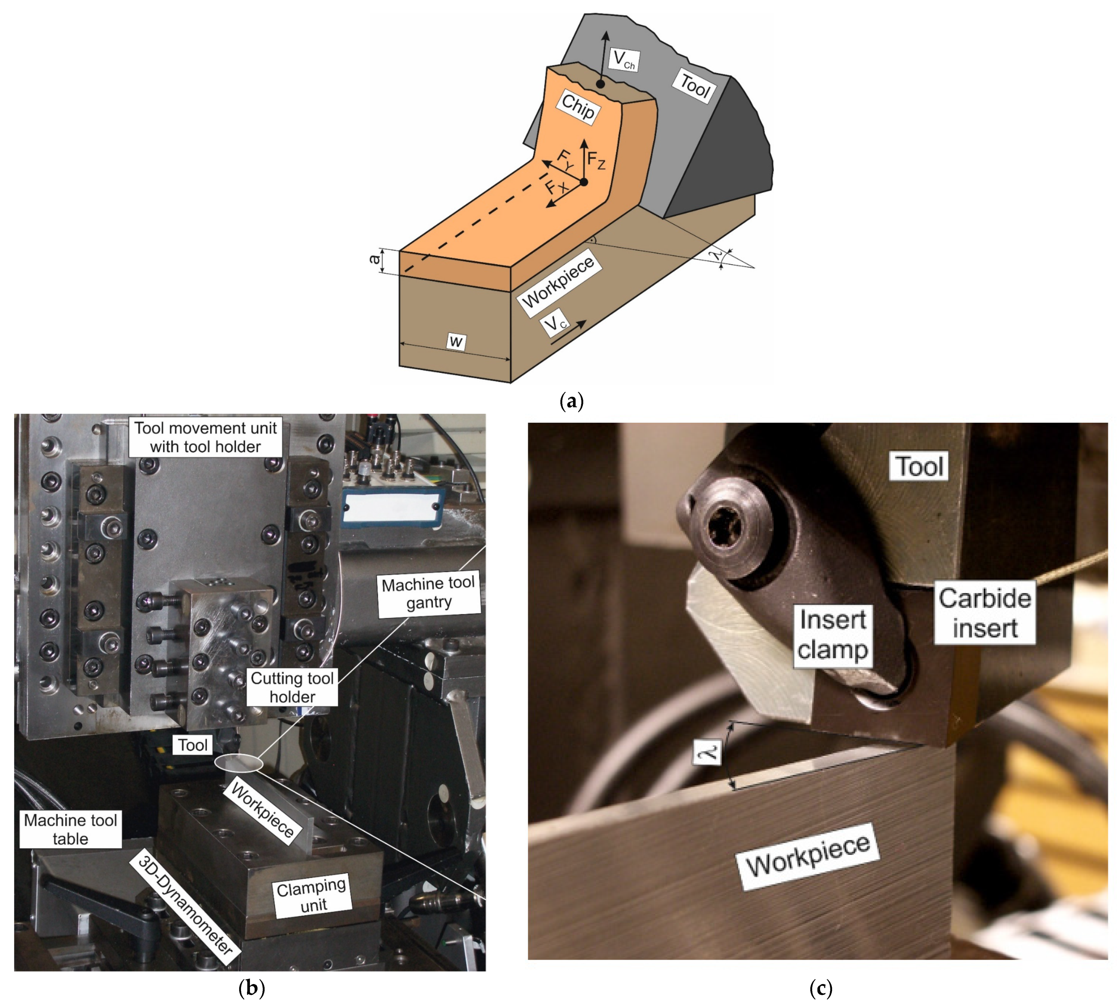
3.1.2. Oblique Cutting Test

Experimental studies to measure cutting forces were carried out in the process of oblique free cutting, the principal scheme of which is shown in Figure 1a. A special experimental stand (Institute for Machine Tool, Stuttgart, Germany) was used to realize the machining process, as shown in Figure 1b. This stand provides a free orthogonal and oblique cutting process [101]. The experimental stand ensures rectilinear movement of the table with the workpiece relative to the stationary tool, with stepless adjustment of cutting speed from 0 to 200 m/min [102]. The well-known AISI 1045 heat-treated structural steel was chosen as the machined material. The mechanical and thermal properties of AISI 1045 steel are given in Table 2. The AISI 1045 steel workpieces were pre-ground to ensure the necessary side parallelism. To ensure a homogeneous material structure and the absence of residual stresses, the workpieces were annealed after grinding. The final size of the workpiece was 170 mm × 65 mm × 3 mm. The hardness of the workpieces after annealing was 180 HB (1800 MPa).
Replacement carbide inserts SNMG-SM-1105 (Sandvik Coromant, Sandviken, Sweden) were used as cutting elements. Table 2 also shows the mechanical and thermal properties of these carbide cutting inserts. Installation of a replaceable carbide insert in the tool body at a predetermined rake angle and subsequent grinding of the tool clearance face ensured the cutting wedge geometry required for a stable cutting process [102]. During the experimental studies, the tool rake angle was γ = 0°, the tool clearance angle was α = 8°, and the cutting edge curvature radius was ρ = 20 μm.
Experimental studies were carried out at different cutting speeds, different depths of cut (undeformed chip thickness), and different inclination angles of the cutting edge λ (see Figure 1a,c). To change the angle λ, the tool head with the clamped insert was mounted in the tool body, with the possibility of rotation around its longitudinal axis (see Figure 1c). For measurement of the cutting forces, the workpiece was clamped in a three-component dynamometer Kistler type 9121 (Kistler Group, Winterthur, Switzerland) with a special clamping unit (see Figure 1b). To improve the reliability of the cutting force component measurements, the used dynamometer was additionally calibrated with static loading along the vector directions of the cutting force components. The cutting speed VC was applied at three levels: 48 m/min, 96 m/min, and 144 m/min [103]. The cutting depth (unformed chip thickness) a was applied at three levels: 0.1 mm, 0.15 mm, and 0.2 mm. The inclination angle of the tool cutting edge λ was applied at four levels: 0°, 15°, 30°, and 45°.
The oblique cutting process was repeated for each set of cutting speeds, cutting edge inclination angles, and cutting depths at least 5 times. The measurement results of the cutting forces were averaged over these repetitions. The maximum deviation in measuring the cutting forces was no more than 11%.

3.2. Methods

An analytical model is used as the main method for determining the kinetic characteristics of the oblique cutting process. The main statements and accepted assumptions, as well as the algorithm of this model, are outlined below. The Johnston–Cook constitutive equation is used to determine the mechanical properties of the machined material for the analytical cutting model. The initial values of the constitutive equation parameters are determined experimentally and specified by the inverse method using numerical simulation of the oblique cutting process. The methodological aspects of this approach are outlined at the end of the chapter.

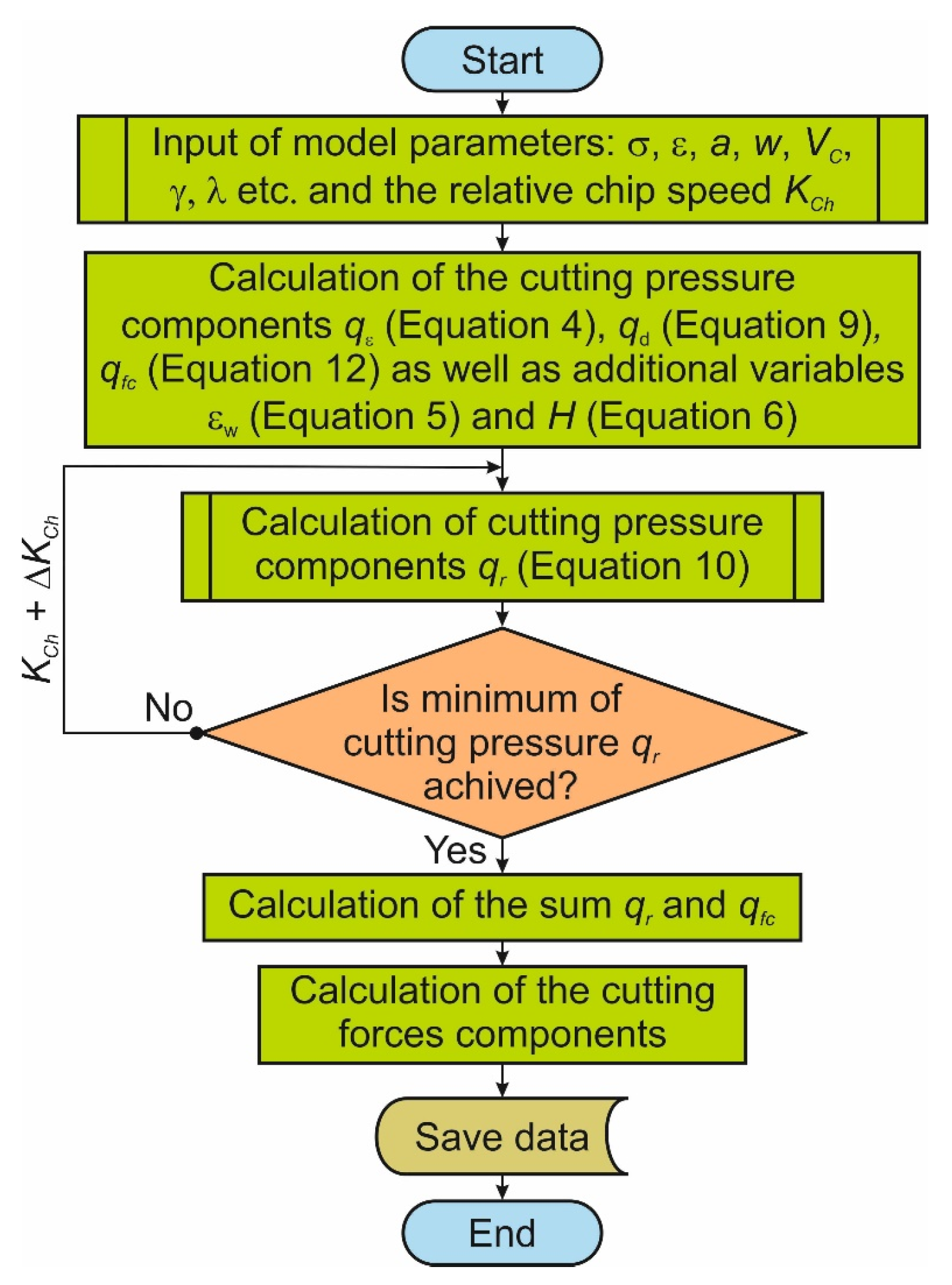
3.2.1. Analytical Cutting Model

The analytical model of oblique cutting is based on the energy approach using the extreme principles of continuum mechanics and the statements of the plastic flow material theory [84]. The cutting process is considered as a continuous plastic deformation process of the machined material. This process is viewed as a set of two simultaneous acts: plastic deformation of the subsurface layer of the workpiece and subsequent chip formation. The following assumptions were accepted in the model development:
  • Analysis of chip formation is based on the cutting scheme with a single shear plane [10,23,24,82]. According to this scheme, the machined material is deformed in a thin layer in the vicinity of the shear plane. The speed field during chip formation is disruptive. The speed break boundary is the shear plane. In the shear plane, the tangential velocities suffer a break, while the normal speed retains its value;
  • The machined material is rigidly plastic and subject to strain-hardening. This corresponds to the conditions of complete cold deformation;
  • Power in the cutting process is consumed for plastic deformation in the shear plane, for overcoming the friction forces on the rake and clearance faces, and for crack propagation work associated with the formation of new surfaces;
  • New surfaces for chip formation arise in front of the cutting wedge in the area of wedge rounding. They are formed due to crack propagation in the direction of the cutting speed vector;
  • The analysis of the oblique cutting process is performed in cutting pressure terms;
  • Friction on the rake and clearance faces is assumed to be proportional to the normal contact pressure, i.e., described by Coulomb–Amonton’s law;
  • The friction coefficient does not reach its limit, which is defined by the Tresca–Saint-Venant criterion [105]. Contact on the clearance face of the cutting wedge is limited by the wear field.
Based on the accepted assumptions, the energy balance equation expressed in terms of cutting power is presented as follows:
P C = F C · V C = P ε + P f r + P f c + P d ,
where PC is the total power of the cutting process; FC is the resultant cutting force; VC is the cutting speed; Pε is the plastic deformation power of the machined material; Pfr is the power of friction between the chip and the tool rake face; Pfc is the power of friction between the tool clearance face and the workpiece machined surface; Pd is the damage power of new surface formation.
Since further analysis is performed in terms of cutting pressure, Equation (2) of the power balance is transformed into the balance equation of the corresponding pressures. This is performed by dividing Equation (2) by the product of V C · a · w · σ S :
P C V C · a · w · σ S = q C = q ε + q f r + q f c + q d ,
where a is the depth of cut (undeformed chip thickness); w is the cutting width; σS is the flow stress of the machined material; qC is the cutting pressure; qε is the portion of the cutting pressure caused due to machined material deformation in the primary cutting zone; qfr is the portion of the cutting pressure caused as a result of friction between the tool rake face and the chip, i.e., friction in the secondary cutting zone; qfc is the portion of the cutting pressure caused as a result of friction between the tool clearance face and the machined workpiece surface, i.e., friction in the tertiary cutting zone; qd is the portion of the cutting pressure caused as a result of the machined material damage during the new surface formation of the chip and the machined material.
The portion of the cutting pressure caused due to machined material deformation in the primary cutting zone is defined as follows:
q ε = 1 + H · ε w 2 · ε w ,
where εw is the final true strain of the machined material in the primary cutting zone; H is the hardening intensity coefficient of the machined material.
The value of εw can be determined by various dependencies (see, for example, [23,24,103]). In the described analytical model, the final true strain of the machined material in the primary cutting zone εw is defined by the following dependence:
ε w = 1 3 · cos γ · ( K C h + 1 K C h 2 · sin γ ) 2 + λ 2 · cos 2 γ ,
where λ is the inclination cutting angle for main edge; KCh is the relative chip speed.
The hardening intensity coefficient H of the machined material is determined according to the following dependence:
H = σ f σ i σ i · ε a
where σi and σf are the true flow stresses of the initial and deformed machined material; εa is the average strain of the machined material.
The relative chip speed is determined by the following dependence:
K C h = V C h V C
Equation (7) is the inverse of the chip compression ratio Ka:
K C h = 1 K a
The portion of the cutting pressure caused as a result of the machined material damage during the new surface formation of the chip and the machined material is determined as follows:
q d = A d a · σ S · 1 + K C h 2
where Ad is the specific work of crack propagation during chip formation.
The portion of the cutting pressure caused due to machined material deformation in the primary cutting zone qε, the portion of the cutting pressure caused as a result of the machined material damage during the new surface formation of the chip and the machined material qd, and the portion of the cutting pressure caused as a result of friction between the tool rake face and the chip (friction in the secondary cutting zone) qfr jointly form the portion of cutting pressure acting on the tool rake face (in the secondary cutting zone) qr:
q r = q ε + q d 1 sin ρ cos ( γ ρ ) · K C h
where p is the friction angle determined by the friction coefficient on the tool rake face fr; ρ = arctan f r .
The relative cutting speed KCh is determined based on the portion of cutting pressure acting in the secondary cutting zone. For this purpose, the well-known variational principle of tending the system potential energy toward the minimum is used [106]. This principle has also been used to develop various analytical cutting models (see, e.g., [13,17,82]). In the analytical model of oblique cutting, this principle is expressed as follows:
P P C : q r 0 ; d ( q r ) d K C h = 0
where is the existence space of the cutting process conditions.
Using the value of the relative cutting speed KCh, the portion of the cutting pressure acting in the secondary cutting zone qr is determined. This portion of the cutting pressure is added with the portion of the cutting pressure caused as a result of friction between the tool clearance face and the machined workpiece surface, i.e., friction in the tertiary cutting zone qfc. The pressure at the wear field of the tool clearance face is defined as the pressure when a flat punch is pressed into a half-space in the presence of contact friction [83] (see also [82,84]). In this regard, the portion of the cutting pressure consumed by friction between the tool clearance face and the machined surface of the workpiece is defined by the following equation:
q f c = 1 + π 2 1 1.36 · f c
where fc is the friction coefficient on the tool clearance face.
The sum of the cutting pressure portions qr and qfc determines the required components of the cutting forces. A flowchart of the software-implemented algorithm for calculating the kinetic characteristics of the oblique cutting process is shown in Figure 2.
More detailed information on the equation’s derivation of the separate cutting pressure components is given in [84] and related studies.

3.2.2. FEM Cutting Model

The parameter values of the Johnson–Cook constitutive equation, determined from experimental data of specimen compression mechanical tests and the cutting process, are refined by the inverse method through numerical simulation of the oblique cutting process. Numerical modeling also refines the values of these parameters for specific areas of cutting conditions and modes, tool geometric parameters, and other values impacting the kinetic characteristics of the cutting process. The numerical simulation process is performed using the developed spatial finite element model of oblique cutting.
The geometric model with a mesh and boundary conditions of the developed finite element model is shown in Figure 3. The model is developed based on an updated implicit Lagrangian formulation method. The workpiece machined material is modeled as an isotropic plastic-type material, and the tool material is modeled as absolutely rigid [99]. In the cutting zones and in the area of subsequently formed chips, the mesh was modeled much finer than on the rest of the workpiece. The initial mesh of the workpiece model contained about 67,845 elements and about 14,138 nodes. The edge length of the largest element of the workpiece model was about 0.126 mm, and the edge length of the smallest element was about 0.018 mm. The initial tool model mesh contained about 26,878 elements and about 6158 nodes. In this case, the edge length of the largest element was about 0.082 mm, and the edge length of the smallest element was about 0.0203 mm.
The workpiece was rigidly fixed in all coordinate directions. The tool was given movement in the negative X-axis direction, with a cutting speed of VC. The tool was rigidly fixed in the direction of the Y and Z axes. Initial thermal conditions of room temperature Tr were set on the tool’s left side and top, as well as on the bottom and left side of the workpiece. The depth of cut a (undeformed chip thickness) was realized by tool penetration into the workpiece in the negative direction of the Z-axis at this value. To realize the oblique cutting process, the tool was set in relation to the workpiece at a given angle λ of its cutting edge inclination. For this purpose, the tool was rotated around the Z-axis by the value of the angle λ.
As mentioned earlier, the model of the machined material is described by the Johnson–Cook constitutive equation [98,99]. Initial values of the constitutive equation parameters were determined from the experimental data of mechanical compression tests and the oblique cutting process following the methodology detailed in [100]. The contact interaction between the tool and the chip and the workpiece in the secondary and tertiary cutting zones [107] is described using the Coulomb model. In the areas of expected contact interaction, local friction coefficients corresponding to the contact conditions were established. The friction windows were used to enter these local coefficients [108]. The damage model of the machined material with chip formation [109], which must necessarily be applied when modeling the machining of materials such as titanium and nickel alloys or austenitic and some hardened steels, i.e., materials that produce segmented (serrated) chips (see, for example, [110]), was not applied in the developed FE model of oblique cutting. In this case, the simulation of the machined material damage (AISI 1045 steel), accompanied by the formation of a flow chip, is realized automatically through a software algorithm (Deform v. 11.0, Scientific Forming Technologies Corporation, Columbus, Ohio, USA).

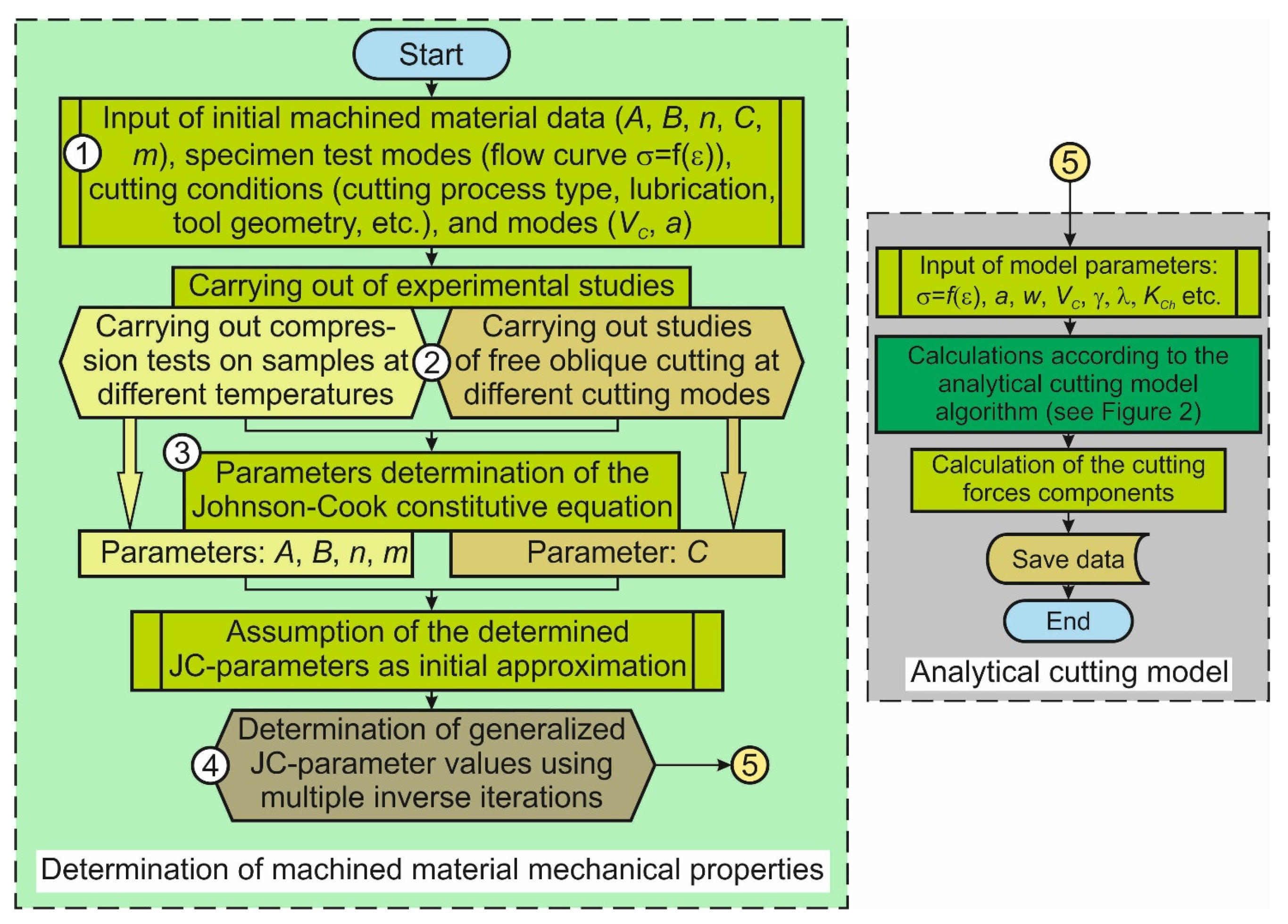
3.2.3. Methodology for Determining the Mechanical Properties of Machined Material

The mechanical properties of the machined material for application in the analytical model of oblique cutting are determined in this study using the Johnson–Cook constitutive equation [98,99]. For efficient use in the analytical model, the parameters of the constitutive equation—initial yield stress A, strain hardening coefficient B, power factor of stress hardening n, rate hardening coefficient C, and power factor of thermal softening m—must be generalized. A constitutive equation with such parameter values should describe the mechanical properties of the machined material for a certain (predetermined) region for different cutting conditions, cutting modes, tool geometric parameters, etc. [111,112]. A flowchart of the algorithm for determining the generalized parameters of the constitutive equation and implementation of machined material mechanical properties in the calculation algorithm of the analytical cutting model is shown in Figure 4. After input of the initial data, including machined material data, modes of mechanical compression tests, and conditions and modes of the cutting process (see Figure 4, step 1 of the algorithm flowchart), compression tests at different specimen temperatures as well as experimental studies of the kinetic characteristics of the oblique cutting process for different cutting modes are performed (see Figure 4, step 2). The third step of the algorithm is devoted to determining the parameter values of the constitutive equation. From mechanical compression tests at different temperatures, the values of the parameters A, B, n, and m are determined using approximation and fitting of the flow curves of the machined material. At the same step of the algorithm, the value of the parameter C is determined from the experimental data of the cutting process. The methodology presented in [100] was used to determine these parameters. The constitutive equation parameters determined at the third step of the algorithm are taken as the initial values. The fourth step of the developed algorithm is devoted to specifying the previously defined parameter values by numerical simulation of the oblique cutting process using the developed finite element cutting model (see Section 3.2.2). This step generalizes these parameters to a certain range for different values of cutting conditions and modes, as well as tool geometric parameters [111,112]. According to the constitutive equation with generalized parameters, the mechanical properties of the machined material at known values of strain, strain rate, and temperature are determined. The sought values of mechanical properties are transferred to the algorithm branch of the analytical cutting model at the fifth step. The values of strain, strain rate, and temperature were determined using the analytical model.

4. Results and Discussion

4.1. Experimental Studies

Following the developed methodology for determining and specifying the constitutive equation parameters (see Section 3.2.3), firstly, mechanical compression tests of specimens from the machined material and experimental studies of forces during the oblique cutting process are carried out. Figure 5 exemplifies the results of compression tests on specimens from the machined material at different temperatures of the tested specimen.
During the tests, the specimen temperature was varied stepwise from 20 °C to 800 °C. Increasing the specimen temperature in the region up to 400 °C caused an expected decrease in the flow stress of the tested material to a value of about 100 MPa (see Figure 5). A further increase in the tested specimen temperature up to 800 °C significantly reduced the mechanical properties of the machined material. The compression test results were further used to identify the initial values of the constitutive equation parameters. The numerical values of these parameters were determined by approximating the obtained flow curves with the Johnson–Cook equation.
Experimental studies of the kinetic characteristics of the oblique cutting process at varying cutting speeds and depths of cut for different tool cutting edge inclination angles λ are shown in Figure 6 and Figure 7. The dependencies of cutting force, thrust force, and lateral force on cutting speed when the cutting speed was varied from 48 m/min to 144 m/min are shown in Figure 6. The cutting force FX decreases with increasing cutting speed; the main decrease occurs when the cutting speed VC increases from 48 m/min to 96 m/min (see Figure 6a). A further increase in cutting speed leads to a slight decrease in cutting force FX. Such behavior of the cutting force is probably explained by the predominant influence of thermal softening of the machined material rather than by the material rate hardening with the increase of the cutting speed [23,101,103]. In contrast, the thrust force FZ increases slightly with increasing cutting speed (see Figure 6b). The main trend of this increase is observed when the cutting speed VC increases from 96 m/min to 144 m/min and the tool cutting edge inclination angles λ = 0° (orthogonal cutting case). Most likely, when forming the thrust component of the cutting force FZ, as well as the lateral component FY, the rate hardening influence of the machined material is largely compensated by the thermal softening of this material [101,103]. The lateral component FY of the resultant cutting force, as well as the thrust force FZ, increases insignificantly with increasing cutting speed (see Figure 6c).
A slightly higher increase in lateral force with increasing cutting speed is observed for the tool cutting edge inclination angle λ = 45°. At the same time, there is a significant increase in lateral force FY with increasing tool cutting edge inclination angle λ. In the case of orthogonal cutting, at the angle λ = 0°, this force is clearly equal to 0. At the transition from orthogonal cutting to oblique cutting, the lateral force FY increases significantly with the increase of the tool cutting edge inclination angle, and at the angle λ = 45°, it exceeds even the cutting force FX. With a high degree of certainty, this behavior of lateral force FY is explained by the occurrence and presence of additional deformation of the machined material in the Y-axis direction during the oblique cutting process. At the transition from orthogonal to oblique cutting, the final deformation of the machined material is supplemented with two additional shear deformations, and the stress tensor is supplemented with non-zero tangential components. These features of the oblique cutting process are formally described and accounted for in the analytical cutting model [84].
Dependences of cutting force FX, thrust force FZ, and lateral force FY on the depth of cut a (undeformed chip thickness) when changing the cutting depth from 0.1 mm to 0.2 mm are shown in Figure 7. With the increase in depth of cut a, all components of cutting forces increase in direct proportion to the increase in depth of cut. The greatest degree of increase is observed in the cutting force FX (see Figure 7a). In this case, the increase in cutting force FX is almost identical for all tool cutting edge inclination angles λ. The same degree of force increase with increasing depth of cut is also observed when analyzing the thrust force FZ (see Figure 7b). A somewhat different change characteristic is seen in lateral force FY. The degree of increase in force FY with increasing depth of cut a grows with increasing the tool cutting edge angle λ (see Figure 7c).
The general increase in the cutting force components with increasing depth of cut is explained by the corresponding depth of cut increase in the material volume removed per unit time and the corresponding increase of the machined material deformation. The increase in the growth degree of lateral force FY with increasing the tool cutting edge inclination angle can be explained by the additional growth of shear deformations and stress tensor tangential components of the machined material with increasing the angle λ.
The experimental results presented above were used to determine the Johnson–Cook constitutive equation parameters. For this purpose, a separate parameter determination algorithm was used [100]. According to this algorithm, the parameters of initial yield stress A, stress coefficient of strain hardening B, and power coefficient of strain hardening n were initially determined using the fitting of the flow curve at room temperature of the specimen (see, e.g., Figure 5).
Then, the power coefficient of thermal softening m was determined based on the results of the specimen’s compression tests at different temperatures using a flow curve fitting and averaging of the results [100]. From experimental studies of the kinetic characteristics of the oblique cutting process, strain rate coefficient C was determined [100]. The constitutive equation parameters determined from the experimental data are summarized in Table 3.
According to the developed methodology (see Section 3.2.3), the values of these parameters were taken as initial values and then specified by the inverse method using the developed finite element model of oblique cutting.

4.2. Numerical Simulation

Validation of the developed finite element model for the oblique cutting process (see Section 3.2.2) was performed based on the simulation of thermomechanical characteristics of the cutting process at different tool cutting edge inclination angles λ: components of cutting forces, strain effective, stress effective, and temperature. Figure 8 exemplifies the main thermomechanical characteristics of the cutting process for angles λ = 15° and λ = 30°.
An analysis of the simulated thermomechanical characteristics of the cutting process established the validity of the developed finite element model. This ensures its successful application in the determination of the Johnson–Cook constitutional equation parameters using the inverse method. The process characteristic—the cutting force component FX—was used as an objective value of the cutting process characteristics to determine the required parameters. For the determination of the constitutive equation’s generalized parameters, the methodology described in [111,112] was used. The values of the generalized parameters determined from the numerical simulation of the oblique cutting process are presented in Table 4.

4.3. Calculation of Cutting Forces Using an Improved Analytical Model

The generalized parameters of the constitutive equation presented in Table 4 are used in the analytical model of oblique cutting to specify the mechanical properties of the machined material. To calculate the cutting forces using an improved analytical model, the mechanical properties of the machined material were determined according to the Johnson–Cook model (see Equation (1)). The actual flow stress value of the machined material σS was determined using this equation. The following values of the variables included in Equation (1) were used to calculate the value σS: the final true strain of the machined material in the primary cutting zone εw was used as strain ε; the reference value of the strain rate ε ˙ 0 was taken as 1 s−1; the value of the strain rate was determined according to the corresponding cutting speed VC; the value of actual temperature T was taken as equal to the temperature of the machined material in the primary cutting zone. For this purpose, the temperature values measured and determined by calculation on the outside of the chip in the chip-forming area were used [113,114]. Temperature values were determined for each cutting speed separately. To determine the hardening intensity coefficient H of the machined material (see Equation (6)), the value of true initial flow stresses σi and the value of the deformed machined material σf at the initial value and final value of true strain of the machined material in the primary cutting zone, respectively, were used. The values of σi and σf were calculated according to Equation (1).
The values of the cutting force components calculated by the improved analytical model were compared with the experimental values of the forces (see Section 4.1). Figure 9 shows, for cutting speed VC = 96 m/min, the calculated values of cutting force components depending on the depth of cut a (undeformed chip thickness) and the deviations of these values from the corresponding experimental values.
The tendency of the cutting force components calculated using the analytical cutting model corresponds to the change in the measured values of the corresponding forces (see Figure 7 for comparison). In this case, the smallest deviation between measured and calculated values of cutting forces is about 3.6%, and the largest deviation is about 21.8%. The deviation in most compared values of the cutting force components does not exceed 15% (see Figure 9).
Figure 10 shows the relationship between the calculated values of the cutting force components and the cutting speed at different values of the tool cutting edge angle λ. The same figure shows the deviations of the calculated cutting forces from the corresponding experimental values presented in Figure 6. The calculated value trend of the cutting force components calculated using the analytical model of the oblique cutting process shows some thermal softening influence of the machined material due to the increase of the cutting speed (see Figure 10). Such an influence is provided by the influence of constitutive equation parameters on the mechanical properties of the machined material used for calculation. The smallest deviation between measured and calculated values of cutting forces is about 1.1%, and the largest deviation is about 29.7% (see Figure 10). The deviation in most compared values of the cutting force components does not exceed 20%. The trend of the calculated cutting force FX (see Figure 10a) is almost identical to the trend of the measured force FX (see Figure 6a for comparison): an increase in cutting speed leads to a decrease in cutting force FX. The deviations between the measured and calculated values of the cutting force FX are within 15%.
At the same time, the character of change in the calculated values of the thrust force FZ (see Figure 10b) is nearly opposite to the character of change in the measured values of this force (see Figure 6b for comparison). In all probability, the thrust force FZ is predominantly influenced by strain and rate hardening of the machined material rather than its thermal softening at higher cutting speeds. Nevertheless, the deviation of the calculated values of the thrust force FZ from its corresponding experimental values is less than 20% (Figure 10b). The smallest effect on the calculated values of lateral force FY results from an increase in velocity (see Figure 10c). This force is practically independent of the change in cutting speed at tool cutting edge angles from 0° to 30°. A rather low influence, namely a decrease in the lateral force FY, is observed when the tool cutting edge inclination angle is λ = 45°. However, the deviation between the measured and calculated FY lateral force values lies within 20%. The only exception is the deviation of the lateral force FY at a cutting speed of VC = 50 m/min and a tool cutting edge inclination angle of λ = 0°. In this case, this deviation is about 29.7% (see Figure 10c).
The performed analysis shows that the application of the improved analytical model of oblique cutting provides a good possibility of predicting cutting forces at different cutting modes and different tool cutting edge inclination angles. In this case, the difference between the main part of the calculated cutting force values and the corresponding measured values is not more than 20%. Thus, the use of different material models to determine the mechanical properties of the machined material provides satisfactory accuracy of calculations and has a good potential for use in analytical cutting models. In particular, the application of the Johnson–Cook material model in the analytical model of oblique cutting can be recommended for further use.

5. Conclusions

This paper presents the results of the improvement of the analytical model of oblique cutting. The model is improved using the values of machined material mechanical properties, taking into account thermomechanical conditions of the cutting process and a significant change in cutting modes and the tool cutting edge inclination angle. The Johnson–Cook constitutive equation was applied to determine the mechanical properties of the machined material. The determination of the constitutive equation parameters was carried out in two steps: (1) determination of initial parameter values using mechanical compression testing of specimens from the machined material and (2) specifying the values of the constitutive equation parameters, generalized for some regions of cutting modes and tool cutting edge inclination angles, using the inverse method through the finite element model of oblique cutting. The following conclusions can be drawn based on the results of the study:
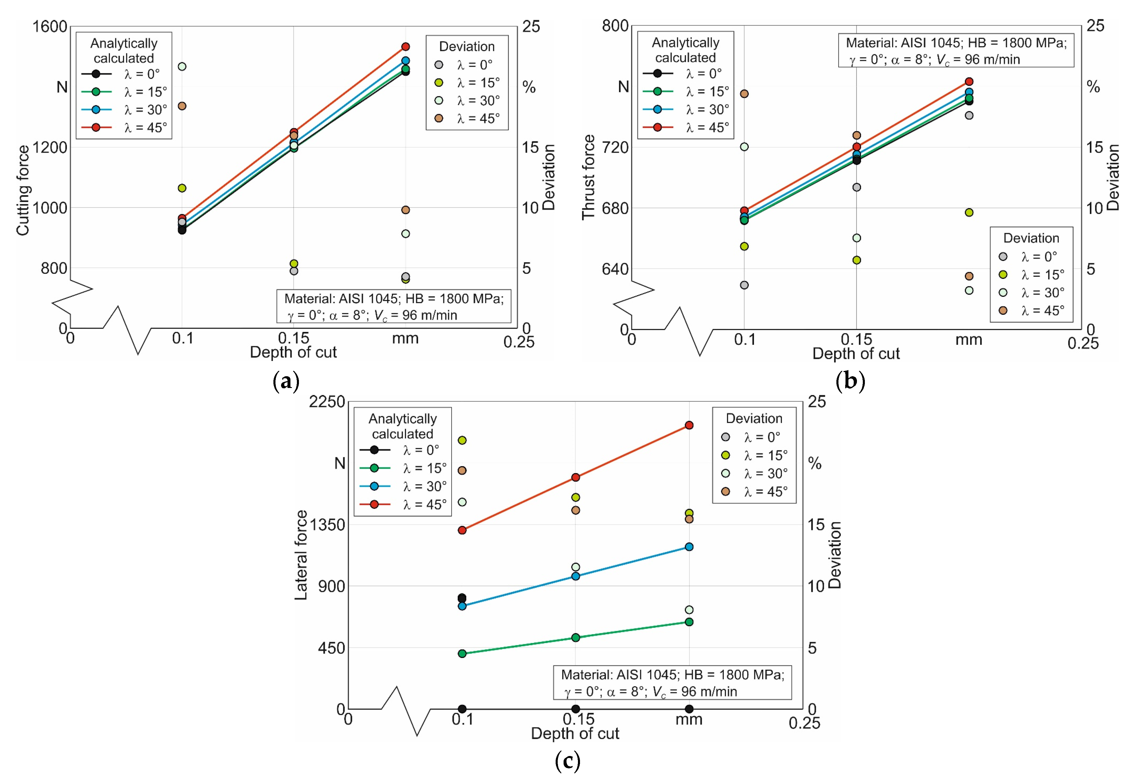
  • The cutting forces calculated using the analytical model of oblique cutting with the use of refined mechanical parameters of the machined material satisfactorily coincide with the corresponding measured values of these forces.
  • The calculated value deviations of the cutting force components when the cutting depth a (undeformed chip thickness) changes from 0.1 mm to 0.2 mm from their measured values in the vast majority of cases do not exceed 15%. The difference between the calculated and measured values of the cutting force components when the cutting speed VC changes from 48 m/min to 144 m/min in the vast majority of cases does not exceed 20%.
  • The developed algorithm for determining the mechanical properties of the machined material using the Johnson–Cook constitutive equation can be successfully used in analytical models of orthogonal and oblique cutting. This is evidenced by the satisfactory coincidence of the measured and analytically calculated kinetic characteristics of the cutting process.
  • The proposed symbiosis of analytical and numerical cutting models is successfully realized by implementing the algorithm for determining the mechanical properties of the machined material into the analytical cutting model.
  • The suggested technique of determining the initial parameters for the analytical cutting model can be extended to determine the parameters of the contact interaction between the tool and the machined material and the chip, as well as to determine the damage parameters of the machined material with chip formation.
  • Thus, improved analytical models of orthogonal and oblique cutting can be successfully used for the optimization of existing machining processes and tool designs, as well as for the purposeful creation of new processes and tools for their implementation.

Author Contributions

Conceptualization, M.S.; methodology, M.S.; software, M.S. and M.A.L.; validation, M.S. and M.A.L.; formal analysis, M.S. and M.A.L.; investigation, M.S. and M.A.L.; resources, M.S.; data curation, M.A.L.; writing—original draft preparation, M.S. and M.A.L.; writing—review and editing, M.S. and M.A.L.; visualization, M.S. and M.A.L.; project administration, M.S. All authors have read and agreed to the published version of the manuscript.

Funding

This study was funded by the German Research Foundation (DFG) under the project HE-1656/175-1 “Development of an analytical model of oblique cutting based on extremal principles of continuum mechanics”.

Data Availability Statement

Not applicable.

Acknowledgments

The authors would like to thank the German Research Foundation (DFG) for their support, which is highly appreciated.

Conflicts of Interest

The authors declare no conflict of interest.

References

  1. Davim, J.P. Machining of Complex Sculptured Surfaces; Springer: London, UK, 2012; 258p. [Google Scholar] [CrossRef]
  2. Andrianto, M.; Wu, Y.R.; Arifin, A. Mathematical modeling on a novel manufacturing method for roller-gear cams using a whirl-machining process. Int. J. Adv. Manuf. Technol. 2023, 125, 5015–5029. [Google Scholar] [CrossRef]
  3. Babichev, D.; Storchak, M. Synthesis of cylindrical gears with optimum rolling fatigue strength. Prod. Eng. Res. Dev. 2015, 9, 87–97. [Google Scholar] [CrossRef]
  4. Finnie, I. Review of the metal-cutting analysis of the past hundred years. Mech. Eng. 1956, 78, 715–721. [Google Scholar]
  5. Arrazola, P.J.; Özel, T.; Umbrello, D.; Davies, M.; Jawahir, I.S. Recent advances in modelling of metal machining processes. Ann. CIRP 2013, 62, 695–718. [Google Scholar] [CrossRef]
  6. Melkote, S.; Liang, S.; Özel, T.; Jawahir, I.S.; Stephenson, D.A.; Wang, B.A. Review of Advances in Modeling of Conventional Machining Processes: From Merchant to the Present. ASME J. Manuf. Sci. Eng. 2022, 144, 110801. [Google Scholar] [CrossRef]
  7. Malishev, V. Essays on the History of the Science of Cutting Materials; TSU: Tolyatti, Russia, 2011; 216p, ISBN 978-5-8259-0624-9. (In Russian) [Google Scholar]
  8. Cocquilhat, C.M. Expériences sur la Resistance Utile Produites dans le Forage. Ann. des Trav. Publics en Belg. 1851, 10, 199–215. [Google Scholar]
  9. Hartig, E.; Teubner, B. Versuche über Leistung und Arbeitsverbrauch der Werkzeugmaschinen; Classic Reprint; Wentworth Press: Sydney, Australia, 2018; 266p, ISBN 10:0270499350. [Google Scholar]
  10. Time, I.A. Mémoire sur le Rabotage des Métaux; Classic Reprint, French Edition; Forgotten Books: London, UK, 2018; 48p, ISBN 13:978-0365617273. [Google Scholar]
  11. Mallock, A. The action of cutting tools. Proc. R. Soc. Lond. 1882, 33, 127–139. [Google Scholar] [CrossRef]
  12. Tresca, H.E. Mémoire sur l’écoulement des corps solides. In Mémoires de l’Académie des Sciences de l’Institut de France; Imprimerie Impériale: Paris, France, 1868; Volume 18, 111p. [Google Scholar]
  13. Zworykin, K.A. Work and Forces Required for Separation of Metal Chips; Russian Printing House: Moscow, Russia, 1893; 91p. (In Russian) [Google Scholar]
  14. Bricks, A.A. Cutting of Metalls (Planing); Stasiulevich Printing House: Sankt-Petersburg, Russia, 1896; 163p. (In Russian) [Google Scholar]
  15. Merchant, M.E. Twentieth century evolution of machining in the United States—An interpretative review. Sadhana 2003, 28, 867–874. [Google Scholar] [CrossRef]
  16. Soo, S.L.; Aspinwall, D.K. Developments in modeling of metal cutting processes. Proc. Inst. Mech. Eng. Part L J. Mater. Des. Appl. 2007, 221, 197–211. [Google Scholar] [CrossRef]
  17. Merchant, M.E. Basic mechanics of the metal cutting process. J. Appl. Mech. 1944, 11, A168–A175. [Google Scholar] [CrossRef]
  18. Merchant, M.E. Mechanics of the metal cutting process II. Plasticity conditions in orthogonal cutting. J. Appl. Phys. 1945, 16, 318–324. [Google Scholar] [CrossRef]
  19. Piispanen, V. Theory of formation of metal chips. J. Appl. Phys. 1948, 19, 876–881. [Google Scholar] [CrossRef]
  20. Lee, E.H.; Shaffer, B.W. The theory of plasticity applied to a problem of machining. J. Appl. Mech. 1951, 18, 405–413. [Google Scholar] [CrossRef]
  21. Shaw, M.C.; Cook, N.H.; Finnel, L. The Shear Angle Relationship in Metal Cutting. J. Fluid Eng. 1953, 75, 273–283. [Google Scholar] [CrossRef]
  22. Palmer, W.B.; Oxley, P.L.B. Mechanics of metal cutting. Proc. Inst. Mech. Eng. 1959, 173, 623–654. [Google Scholar] [CrossRef]
  23. Zorev, N.N. Metal Cutting Mechanics; Pergamon Press GmbH: Frankfurt am Main, Germany, 1966; 526p, ISBN 978-0080107233. [Google Scholar]
  24. Oxley, P.L.B. Mechanics of Machining. An Analytical Approach to Assessing Machinability; Ellis Horwood: Chichester, UK, 1989; 242p, ISBN 13:978-0470213827. [Google Scholar]
  25. Boothroyd, G. Temperatures in Orthogonal Metal Cutting. Proc. Inst. Mech. Eng. 1963, 177, 789–802. [Google Scholar] [CrossRef]
  26. Bao, H.; Stevenson, M.G. An investigation of built-up edge formation in the machining of aluminium. Int. J. Mach. Tool Des. Res. 1976, 16, 165–178. [Google Scholar] [CrossRef]
  27. Kristyanto, B.; Mathew, P.; Arsecularatne, J.A. Development of a variable flow stress machining theory for aluminium alloys. Mach. Sci. Technol. 2002, 6, 365–378. [Google Scholar] [CrossRef]
  28. Adibi-Sedeh, A.H.; Madhavan, V.; Bahr, B. Extension of Oxley’s Analysis of Machining to Use Different Material Models. J. Manuf. Sci. Eng. 2003, 125, 656–666. [Google Scholar] [CrossRef]
  29. Lalwani, D.I.; Mehta, N.K.; Jain, P.K. Extension of Oxley’s predictive machining theory for Johnson and Cook flow stress model. J. Mater. Process. Technol. 2009, 209, 5305–5312. [Google Scholar] [CrossRef]
  30. Tay, A.O.; Stevenson, M.G.; De Vahl Davis, G.; Oxley, P.L.B. A Numerical method for calculating temperature distributions in machining from force and shear angle measurement. Int. J. Mach. Tool Des. Res. 1976, 16, 335–349. [Google Scholar] [CrossRef]
  31. Komanduri, R.; Hou, Z.B. Thermal modeling of the metal cutting process—Part III: Temperature rise distribution due to the combined effects of shear plane heat source and the tool–chip interface frictional heat source. Int. J. Mech. Sci. 2001, 43, 89–107. [Google Scholar] [CrossRef]
  32. Karpat, Y.; Özel, T. Predictive Analytical and Thermal Modeling of Orthogonal Cutting Process—Part I: Predictions of Tool Forces, Stresses, and Temperature Distributions. J. Manuf. Sci. Eng. 2006, 128, 435–444. [Google Scholar] [CrossRef]
  33. Shan, C.; Zhang, X.; Shen, B.; Zhang, D. An improved analytical model of cutting temperature in orthogonal cutting of Ti6Al4V. Chin. J. Aeronaut. 2019, 32, 759–769. [Google Scholar] [CrossRef]
  34. Chen, Y.; Li, H.; Wang, J. Further Development of Oxley’s Predictive Force Model for Orthogonal Cutting. Mach. Sci. Technol. Int. J. 2015, 19, 86–111. [Google Scholar] [CrossRef]
  35. Tlusty, G. Manufacturing Equipment and Processes; Prentice-Hall: Upper Saddle River, NJ, USA, 2000; 928p, ISBN 978020149865. [Google Scholar]
  36. Dargnat, F.; Darnis, P.; Cahuc, O. On the adaptability of cutting model to drilling. In Proceedings of the 12th CIRP Conference on Modelling of Machining Operations, Donostia-San Sebastián, Spain, 7–8 May 2009; ISBN 978-84-608-0865-7. [Google Scholar]
  37. Marinov, V.R. Hybrid analytical-numerical solution for the shear angle in orthogonal metal cutting—Part I: Theoretical foundation. Int. J. Mech. Sci. 2001, 43, 399–414. [Google Scholar] [CrossRef]
  38. Qi, H.S.; Mills, B. Modelling of the dynamic tool-chip interface in metal cutting. J. Mater. Process. Technol. 2003, 138, 201–207. [Google Scholar] [CrossRef]
  39. Moufki, A.; Molinari, A.; Dudzinski, D. Modelling of orthogonal cutting with a temperature dependent friction law. J. Mech. Phys. Solids 1998, 46, 2103–2138. [Google Scholar] [CrossRef]
  40. Dubrovskiy, A.A. Towards the problem of plastic deformation of the sheared layer, Part 2. In Cutting without Adhesion of Contact Surfaces; Institute of Technical Acoustics of the National Academy of Sciences of Belarus: Vitebsk, Belarus, 2004; pp. 22–27. (In Russian) [Google Scholar]
  41. Ozlu, E.; Molinari, A.; Budak, E. Two-zone analytical contact model applied to orthogonal cutting. Mach. Sci. Technol. 2010, 14, 323–343. [Google Scholar] [CrossRef]
  42. Bahi, S.; List, G.; Sutter, G. Analysis of adhered contacts and boundary conditions of the secondary shear zone. Wear 2015, 330–331, 608–617. [Google Scholar] [CrossRef]
  43. Rosenberg, Y.A. Metal Cutting; Kurgan State University: Kurgan, Russia, 2007; 294p, ISBN 5-86328. (In Russian) [Google Scholar]
  44. Nodelman, M.O. Machining by cutting. In Fundamentals of Theory and Practice; Chelyabinsk House of Printing: Chelyabinsk, Russia, 2018; 176p, ISBN 978-5-87184-653-7. (In Russian) [Google Scholar]
  45. Pravednikov, I.S. Theoretical prediction of stresses and cutting forces based on the physical and mechanical properties of materials. Oil Gas Bus. 2006, 1–11. (In Russian) [Google Scholar]
  46. Vorontsov, A.L.; Syltan-Zade, N.M.; Albagachiev, A.U. Problems of theory and practice of material cutting. Development of a new cutting theory. Bull. Mech. Eng. 2008, 7, 56–61. (In Russian) [Google Scholar]
  47. Hucks, H. Plastizitätsmechanische Theorie der Spanbildung. Werkstatt Betr. Z. Maschinenbau Fert. 1952, 85, 1–6. [Google Scholar]
  48. Pugh, H.L.D. Mechanics of cutting process. In Proceedings of the Conference on Technology and Engineering Nanufacturing; The Institute of Mechanical Engineers: London, UK, 1958; Volume 53, pp. 237–254. [Google Scholar]
  49. Stabler, G.V. The Foundational Geometry of Cutting Tool. Proc. Inst. Mech. Eng. 1951, 165, 14–26. [Google Scholar] [CrossRef]
  50. Shaw, M.C.; Cook, N.H.; Smith, P.A. The mechanics of three-dimensional cutting operations. Trans. ASME 1952, 74, 1055–1064. [Google Scholar] [CrossRef]
  51. Colwell, L.V. Predicting the Angle of Chip Flow for Single-Point Cutting Tools. Trans. ASME 1954, 76, 199–203. [Google Scholar] [CrossRef]
  52. Armarego, E.J.A.; Wiriyacosol, S. Oblique machining with triangular form tools—I. Theoretical investigation. Int. J. Mach. Tool Des. Res. 1978, 18, 67–80. [Google Scholar] [CrossRef]
  53. Rubenstein, C. The mechanics of continuous chip formation in oblique cutting in the absence of chip distortion. Part 1—Theory. Int. J. Mach. Tool Des. Res. 1983, 23, 11–20. [Google Scholar] [CrossRef]
  54. Seethaler, R.J.; Yellowley, I. An upper-bound cutting model for oblique cutting tools with a nose radius. Int. J. Mach. Tools Manuf. 1997, 37, 119–134. [Google Scholar] [CrossRef]
  55. Lin, G.C.I.; Mathew, P.; Oxley, P.L.B.; Watson, R.A. Predicting Cutting Forces for Oblique Machining Conditions. Proc. Inst. Mech. Eng. 1982, 196, 141–148. [Google Scholar] [CrossRef]
  56. Arsecularatne, J.A.; Mathew, P.; Oxley, P.L.B. Predicting of chip flow direction and cutting forces in oblique machining with nose radius tools. Proc. Inst. Mech. Eng. 1995, 209, 305–315. [Google Scholar] [CrossRef]
  57. Moufki, A.; Devillez, A.; Dudzinski, D.; Molinari, A. Thermomechanical modelling of oblique cutting and experimental validation. Int. J. Mach. Tools Manuf. 2004, 44, 971–989. [Google Scholar] [CrossRef]
  58. Usui, E.; Hirota, A.; Masuko, M. Analytical Prediction of Three Dimensional Cutting Process—Part I: Basic Cutting Model and Energy Approach. J. Eng. Ind. 1978, 100, 222–228. [Google Scholar] [CrossRef]
  59. Moufki, A.; Molinari, A. A new thermomechanical model of cutting applied to turning operations. Part II: Parametric study. Int. J. Mach. Tools Manuf. 2005, 45, 181–193. [Google Scholar] [CrossRef]
  60. Fu, Z.; Chen, X.; Mao, J.; Xiong, T. An analytical force model applied to three-dimensional turning based on a predictive machining theory. Int. J. Mech. Sci. 2018, 136, 94–105. [Google Scholar] [CrossRef]
  61. Abdellaoui, L.; Khlifi, H.; Bouzid Sai, W. Prediction of turning performances using an equivalent oblique cutting model. Int. J. Adv. Manuf. Technol. 2022, 120, 7735–7753. [Google Scholar] [CrossRef]
  62. Orra, K.; Choudhury, S.K. Mechanistic modelling for predicting cutting forces in machining considering effect of tool nose radius on chip formation and tool wear land. Int. J. Mech. Sci. 2018, 142–143, 255–268. [Google Scholar] [CrossRef]
  63. Karpat, Y.; Özel, T. Analytical and Thermal Modeling of High-Speed Machining with Chamfered Tools. J. Manuf. Sci. Eng. 2008, 130, 011001. [Google Scholar] [CrossRef]
  64. Hu, C.; Zhang, W.; Zhuang, K.; Zhou, J.; Ding, H. On the Steady-State Workpiece Flow Mechanism and Force Prediction Considering Piled-Up Effect and Dead Metal Zone Formation. J. Manuf. Sci. Eng. 2021, 143, 041009. [Google Scholar] [CrossRef]
  65. Hu, C.; Zhuang, K.; Weng, J.; Zhang, X.; Ding, H. Cutting temperature prediction in negative-rake-angle machining with chamfered insert based on a modified slip-line field model. Int. J. Mech. Sci. 2020, 167, 105273. [Google Scholar] [CrossRef]
  66. Wan, M.; Wen, D.-Y.; Ma, Y.-C.; Zhang, W.-H. On material separation and cutting force prediction in micro milling through involving the effect of dead metal zone. Int. J. Mach. Tools Manuf. 2019, 146, 103452. [Google Scholar] [CrossRef]
  67. Babu, B.H.; Rao, K.V.; Ben, B.S. Modeling and optimization of dead metal zone to reduce cutting forces in micro-milling of hardened AISI D2 steel. J. Braz. Soc. Mech. Sci. Eng. 2021, 43, 142. [Google Scholar] [CrossRef]
  68. Albrecht, P. New Developments in the Theory of Metal Cutting Process. Part I: The Ploughing Process in Metal Cutting. J. Eng. Ind. 1960, 82, 348–357. [Google Scholar] [CrossRef]
  69. Waldorf, D.J.; DeVor, R.E.; Kapoor, S.G. A Slip-line Field for Ploughing during Orthogonal Cutting. J. Manuf. Sci. Eng. 1998, 120, 693–699. [Google Scholar] [CrossRef]
  70. Zhou, J.; Ren, J. Predicting cutting force with unequal division parallel-sided shear zone model for orthogonal cutting. Int. J. Adv. Manuf. Technol. 2020, 107, 4201–4211. [Google Scholar] [CrossRef]
  71. Huang, Y.; Liang, S.Y. Force Modeling in Shallow Cuts with Large Negative Rake Angle and Large Nose Radius Tools—Application to Hard Turning. Int. J. Adv. Manuf. Technol. 2003, 22, 626–632. [Google Scholar] [CrossRef]
  72. Aslantas, K.; Ülker, S.; Şahan, Ö.; Pimenov, D.Y.; Giasin, K. Mechanistic modeling of cutting forces in high-speed microturning of titanium alloy with consideration of nose radius. Int. J. Adv. Manuf. Technol. 2022, 119, 2393–2408. [Google Scholar] [CrossRef]
  73. Sahoo, P.; Patra, K.; Singh, V.K.; Gupta, M.K.; Song, Q.; Mia, M.; Pimenov, D.Y. Influences of TiAlN coating and limiting angles of flutes on prediction of cutting forces and dynamic stability in micro milling of die steel (P-20). J. Mater. Process. Technol. 2020, 278, 116500. [Google Scholar] [CrossRef]
  74. Wojciechowski, S.; Matuszak, M.; Powałka, B.; Madajewski, M.; Maruda, R.W.; Królczyk, G.M. Prediction of cutting forces during micro end milling considering chip thickness accumulation. Int. J. Mach. Tools Manuf. 2019, 147, 103466. [Google Scholar] [CrossRef]
  75. Liu, T.; Liu, Y.; Zhang, K. An improved cutting force model in micro-milling considering the comprehensive effect of tool runout, size effect and tool wear. Int. J. Adv. Manuf. Technol 2022, 120, 659–668. [Google Scholar] [CrossRef]
  76. Gao, S.; Duan, X.; Zhu, K.; Zhang, Y. Generic Cutting Force Modeling with Comprehensively Considering Tool Edge Radius, Tool Flank Wear and Tool Runout in Micro-End Milling. Micromachine 2022, 13, 1805. [Google Scholar] [CrossRef]
  77. Ercetin, A.; Aslantas, K.; Özgün, Ö.; Perçin, M.; Patel, G.C.M. Optimization of Machining Parameters to Minimize Cutting Forces and Surface Roughness in Micro-Milling of Mg13Sn Alloy. Micromachines 2023, 14, 1590. [Google Scholar] [CrossRef]
  78. Cai, L.; Feng, Y.; Lu, Y.T.; Lin, Y.F.; Hung, T.P.; Hsu, F.C.; Liang, S.Y. Analytical Model for Temperature Prediction in Milling AISI D2 with Minimum Quantity Lubrication. Metals 2022, 12, 697. [Google Scholar] [CrossRef]
  79. Vereshchaka, A.S.; Kushner, V.S. Cutting of Metals; Moscow High School: Moscow, Russia, 2009; 535p, ISBN 978-5-06-004415-7. (In Russian) [Google Scholar]
  80. Atkins, A.G. Modelling metal cutting using modern ductile fracture mechanics: Quantitative explanations for some longstanding problems. Int. J. Mech. Sci. 2003, 45, 373–396. [Google Scholar] [CrossRef]
  81. Astakhov, V.; Xiao, X. A methodology for practical cutting force evaluation based on the energy spent in the cutting system. Mach. Sci. Technol. 2008, 12, 325–347. [Google Scholar] [CrossRef]
  82. Tsekhanov, J.; Storchak, M. Development of analytical model for orthogonal cutting. Production Engineering. Res. Dev. 2015, 9, 247–255. [Google Scholar] [CrossRef]
  83. Prandtl, L. Über die Härte Plastischer Körper; Nachrichten von der Gesellschaft der Wissenschaften zu Göttingen: Göttingen, Germany, 1920; pp. 74–85. [Google Scholar]
  84. Olenin, L.D.; Storchak, M.; Lekveishvili, M.A. Development of analytical model of bevel cutting. Izv. MGTU MAMI 2014, 8, 123–128. [Google Scholar] [CrossRef]
  85. Kudo, H. Some new slip-line solutions for two-dimensional steady-state machining. Int. J. Mech. Sci. 1965, 7, 43–55. [Google Scholar] [CrossRef]
  86. Fang, N. Slip-line modeling of machining with a rounded-edge tool – Part 1: New model and theory. J. Mech. Phys. Solids 2003, 51, 715–742. [Google Scholar] [CrossRef]
  87. Maity, K.P.; Das, N.S. A class of slipline field solutions for metal machining with sticking-slipping zone including elastic contact. Mater. Des. 2007, 28, 2310–2317. [Google Scholar] [CrossRef]
  88. Gonzalo, O.; Jauregi, H.; Uriarte, L.G.; López de Lacalle, L.N. Prediction of specific force coefficients from a FEM cutting model. Int. J. Adv. Manuf. Technol. 2009, 43, 348–356. [Google Scholar] [CrossRef]
  89. Wan, M.; Li, S.-E.; Yuan, H.; Zhang, W.-H. Cutting force modelling in machining of fiber-reinforced polymer matrix composites (PMCs): A review. Compos. Part A: Appl. Sci. Manuf. 2019, 117, 34–55. [Google Scholar] [CrossRef]
  90. Shan, C.; Zhang, M.; Yang, Y.; Zhang, S.; Luo, M. A dynamic cutting force model for transverse orthogonal cutting of unidirectional carbon/carbon composites considering fiber distribution. Compos. Struct. 2020, 251, 112668. [Google Scholar] [CrossRef]
  91. Liu, C.; Gao, L.; Jiang, X.; Xu, W.; Liu, S.; Yang, T. Analytical modeling of subsurface damage depth in machining of SiCp/ Al composites. Int. J. Mech. Sci. 2020, 185, 105874. [Google Scholar] [CrossRef]
  92. Wang, R.; Zhao, M.; Mao, J.; Liang, S.Y. Force Prediction and Material Removal Mechanism Analysis of Milling SiCp/2009Al. Micromachines 2022, 13, 1687. [Google Scholar] [CrossRef] [PubMed]
  93. Ning, H.; Zheng, H.; Wang, G. Establishment of Analytical Model for CFRP Cutting Force Considering the Radius of the Edge Circle. Materials 2022, 15, 2127. [Google Scholar] [CrossRef] [PubMed]
  94. Li, P.; Wang, S.; To, S.; Sun, Z.; Jiao, J.; Xu, S. High-efficient fabrication of infrared optics with uniform microstructures by a semi-ductile diamond milling approach. Int. J. Adv. Manuf. Technol. 2023, 126, 919–934. [Google Scholar] [CrossRef]
  95. Sun, Z.; To, S.; Li, P.; Wang, S.; Zhang, T. Analytical modelling of cutting forces in ultra-precision fly grooving considering effects of trans-scale chip thickness variation and material microstructure. Int. J. Adv. Manuf. Technol. 2022, 118, 3209–3227. [Google Scholar] [CrossRef]
  96. Sun, Z.; Wang, S.; To, S.; Xu, S.; Guo, G. Modelling and analysis of the specific cutting energy for ultra-precision diamond cutting of Ti6Al4V alloy. J. Manuf. Process. 2023, 85, 844–857. [Google Scholar] [CrossRef]
  97. Chen, X.; Tang, J.; Shao, W.; Hu, B.; Ye, J. An Analytical and Experimental Study on Cutting Characteristics and Transient Cutting Force Modeling in Feed Directional Ultrasonic Vibration-Assisted Cutting of High Strength Alloys. Materials 2022, 15, 7388. [Google Scholar] [CrossRef] [PubMed]
  98. Johnson, G.R.; Cook, W.H. A constitutive model and data for metals subjected to large strains, high strain and high temperatures. In Proceedings of the 7th International Symposium on Ballistics, The Hague, The Netherlands, 19–21 April 1983; pp. 541–547. [Google Scholar]
  99. Heisel, U.; Krivoruchko, D.V.; Zaloha, W.A.; Storchak, M.; Stehle, T. Thermomechanical material models in the modeling of cutting processes. Z. Wirtsch. Fabr. ZWF 2009, 104, 482–491. [Google Scholar] [CrossRef]
  100. Storchak, M.; Rupp, P.; Möhring, H.-C.; Stehle, T. Determination of Johnson–Cook Constitutive Parameters for Cutting Simulations. Metals 2019, 9, 473. [Google Scholar] [CrossRef]
  101. Kushner, V.; Storchak, M. Determining mechanical characteristics of material resistance to deformation in machining. Production Engineering. Res. Dev. 2014, 8, 679–688. [Google Scholar] [CrossRef]
  102. Heisel, U.; Kushner, V.; Storchak, M. Effect of machining conditions on specific tangential forces. Production Engineering. Res. Dev. 2012, 6, 621–629. [Google Scholar] [CrossRef]
  103. Kushner, V.; Storchak, M. Determination of Material Resistance Characteristics in Cutting. Procedia CIRP 2017, 58, 293–298. [Google Scholar] [CrossRef]
  104. Storchak, M.; Stehle, T.; Möhring, H.-C. Determination of thermal material properties for the numerical simulation of cutting processes. Int. J. Adv. Manuf. 2021, 118, 1941–1956. [Google Scholar] [CrossRef]
  105. Lubliner, J. Plasticity Theory; Dover Publications Inc.: Mineola, NY, USA, 2008; 528p, ISBN 978-0486462905. [Google Scholar]
  106. Chakrabarty, J. Theory of Plasticity, 3rd ed.; Elsevier: Amsterdam, The Netherlands, 2012; 896p, ISBN 978-0080481364. [Google Scholar]
  107. Heisel, U.; Krivoruchko, D.V.; Zaloha, W.A.; Storchak, M.; Stehle, T. Thermomechanical exchange effects in machining. Z. Fuer Wirtsch. Fabr. ZWF 2009, 104, 263–272. [Google Scholar] [CrossRef]
  108. Storchak, M.; Möhring, H.-C.; Stehle, T. Improving the friction model for the simulation of cutting processes. Tribol. Int. 2021, 167, 107376. [Google Scholar] [CrossRef]
  109. Heisel, U.; Krivoruchko, D.V.; Zaloha, W.A.; Storchak, M.; Stehle, T. Breakage models for the modeling of cutting processes. ZWF Z. Fuer Wirtsch. Fabr. 2009, 104, 330–339. [Google Scholar] [CrossRef]
  110. Storchak, M.; Jiang, L.; Xu, Y.; Li, X. Finite element modeling for the cutting process of the titanium alloy Ti10V2Fe3Al. Production Engineering. Res. Dev. 2016, 10, 509–517. [Google Scholar] [CrossRef]
  111. Storchak, M.; Stehle, T.; Möhring, H.-C. Determination of the Shear Angle in the Orthogonal Cutting Process. J. Manuf. Mater. Process. 2022, 6, 132. [Google Scholar] [CrossRef]
  112. Storchak, M.; Drewle, K.; Menze, C.; Stehle, T.; Möhring, H.C. Determination of the Tool–Chip Contact Length for the Cutting Processes. Materials 2022, 15, 3264. [Google Scholar] [CrossRef] [PubMed]
  113. Heisel, U.; Storchak, M.; Krivoruchko, D. Thermal effects in orthogonal cutting. Production Engineering. Res. Dev. 2013, 7, 203–211. [Google Scholar] [CrossRef]
  114. Storchak, M.; Kushner, V.; Möhring, H.-C.; Stehle, T. Refinement of temperature determination in cutting zones. J. Mech. Sci. Technol. 2021, 35, 3659–3673. [Google Scholar] [CrossRef]
Figure 1. Experimental setup for the realization of the oblique cutting process: (a) scheme of oblique cutting; (b) experimental setup for cutting force measurement; (c) position of the cutting insert relative to the workpiece.
Metals 13 01750 g001
Figure 2. Flowchart for calculation of the cutting forces.
Metals 13 01750 g002
Figure 3. Initial geometry, boundary conditions, and mesh of the FE oblique cutting model.
Metals 13 01750 g003
Figure 4. Flowchart for determining the generalized values of machined material mechanical properties and implementation of these values in the calculation algorithm of the analytical cutting model.
Metals 13 01750 g004
Figure 5. Flow curves of the machined material at different specimen temperatures obtained from compression tests.
Metals 13 01750 g005
Figure 6. Cutting forces depending on the cutting speed: (a) cutting force; (b) thrust force; (c) lateral force.
Metals 13 01750 g006
Figure 7. Measured cutting forces depending on the depth of cut (undeformed chip thickness): (a) cutting force; (b) thrust force; (c) lateral force.
Metals 13 01750 g007
Figure 8. Simulation of oblique cutting characteristics: (a) workpiece and chip strain at the cutting edge inclination angle λ = 15°, (b) workpiece and chip strain at the cutting edge inclination angle λ = 30°, (c) effective stress in the workpiece and chip at the cutting edge inclination angle λ = 15°, (d) effective stress in the workpiece and chip at the cutting edge inclination angle λ = 30°, (e) temperature distribution in the workpiece and chip at the cutting edge inclination angle λ = 15°, and (f) temperature distribution in the workpiece and chip at the cutting edge inclination angle λ = 30°.
Metals 13 01750 g008
Figure 9. Analytically calculated cutting forces depending on the depth of cut (undeformed chip thickness): (a) cutting force; (b) thrust force; (c) lateral force.
Metals 13 01750 g009
Figure 10. Analytically calculated cutting forces depending on the cutting speed (undeformed chip thickness): (a) cutting force; (b) thrust force; (c) lateral force.
Metals 13 01750 g010
Table 1. Chronological overview of the analytical model’s evolution.
No.YearAuthor(s)Study Results
1.1851Cocquilhat, C.M. [8]The first scientific studies of the cutting process. Study of process energy in the drilling process.
2.1868Tresca, H.E. [12]The main mechanism of chip formation is the plastic deformation of the machined material. Chips during metal cutting are formed as a result of compression in the tool front.
3.1870Time, I.A. [10]Chip formation model with a single shear plane. The work input to the cutting zone is consumed by plastic deformation in the shear plane.
4.1893Zworykin, K.A. [13]Cutting model based on the principle of minimum potential energy. The energy balance equation takes into account the friction forces on the tool rake face.
5.1896Bricks, A.A. [14]A chip formation model with a wedge fan-shaped shear zone. A force equilibrium system is developed.
6.1945Merchant, M.E. [18]Chip formation model with a single shear plane. The shear angle depends on the machined material properties.
7.1948Piispanen, V. [19]A chip formation model with sequential shear elements (volumes) of the cutting layer.
8.1949Lee, E.H.; Shaffer, B.W. [20]A model with a plastic zone located in the chip above the shear plane. The shear plane is considered to be the lower boundary of this zone. The slip line method is used for analysis.
9.1951Stabler, G.V. [49]Oblique cutting model. Geometric analysis of cutting tool edge. The chip flow law is established.
10.1960Albrecht, P. [68]Model with a single shear plane for tools with rounded tips. Ploughing forces are taken into account.
11.1965Kudo, H. [85]Orthogonal cutting model with slip line fields. The cutting forces, chip curl radius, chip thickening coefficient, and the tool chip contact length as a function of the main cutting edge inclination angle and friction stress are calculated.
12.1966Zorev, N.N. [23]Chip formation model with a straight line fan. Tangential stresses in cutting and compression tests are equal in the case of equal strains.
13.1989Oxley, P.L.B. [24]A model for orthogonal and oblique cutting with a single shear plane and a slip line field. This field consists of two parallel slip lines. The effects of strain, strain rate, and temperature are taken into account.
14.1998Waldorf, D.J. et al. [69]A slip line model for predicting ploughing forces in orthogonal cutting.
15.2001Marinov, V.R. [37]Oxley model improvement takes into account the effect of deformation and strain rate in the secondary cutting zone.
16.2003Fang, N. [86]A slip line model divided into 27 sub-areas.
17.2003Adibi-Sedeh, A.H. et al. [28]Oxley model improvement through the application of different rheological material models.
18.2003Huang, Y.; Liang, S.Y. [71]Model for turning operations with tool tip radius and negative rake angle. Ploughing forces are taken into account.
19.2003Atkins, A.G. [80]Chip formation model with a single shear plane. The damage work of chip formation is taken into account. The impact toughness of the machined material is used to determine the damage work.
20.2004Moufki, A. et al. [57]An oblique cutting model takes into account the properties of the tool and the machined material, as well as general principles of mechanics, heat transfer, and tribology. The value of the chip flow angle is determined.
21.2005Moufki, A.; Molinari, A. [59]A chip formation model for three-dimensional turning conditions that takes into account thermomechanical effects.
22.2007Rosenberg, Y.A. [43]Model with a single shear plane. The tangential stresses in the shear plane are determined using the mechanical properties of the machined material’s initial state.
23.2008Vorontsov, A.L. et al. [46]A model with a rectangular zone in the tool front, the lower boundary of which is a continuation of the cutting plane. Friction stresses on the contact faces are determined by Siebel’s law.
24.2008Karpat, Y.; Özel, T. [63]A chip formation model for a tool with a hardening chamfer. The presence of a stagnant zone at the tool tip is taken into account.
25.2008Astakhov, V.; Xiao, X. [81]A model based on the energy analysis method. The damage power of new surface formation in the shear plane is taken into account.
26.2009Dargnat, F. et al. [36]Improvement of the Oxley model. The equations for determining the strain and strain rate are developed for three cutting zones: the zone of chip formation, the zone of contact between the tool and the chip, and the zone at the tool tip.
27.2009Kushner, V.S. [79]A model of chip formation using a tool with a stabilizing chamfer. A material rheological model that takes into account the simultaneous effects of strain and strain rate hardening as well as temperature softening.
28.2010Ozlu, E. et al. [41]A model that takes into account the plastic contact area and the elastic–plastic contact area in the interaction zone between the tool rake face and the chip.
29.2014Olenin, L.D. et al. [84]An oblique cutting model based on the principle of potential energy minimum. The ductile damage power during the formation of new surfaces is taken into account. The specific work of crack propagation is used for this purpose.
30.2015Tsekhanov, J.; Storchak, M. [82]Orthogonal cutting model based on the principle of minimum potential energy. Friction power on the tool clearance face is considered using the slip line method.
31.2018Orra, K.; Sounak, K. [62]A model for predicting cutting forces taking into account tools with rounded tips and tool wear.
32.2019Wan, M. et al. [66]A material separation model for the front of the cutting edge for theoretical calculation of the stagnant zone shape in micro-milling.
33.2020Hu, C. et al. [65]Slip line field model for machining with a tool using an insert with a hardening chamfer and considering the thermal load’s effect on the tool rake face.
34.2022Aslantas, K. et al. [72]Mechanical model of micro-turning. Cutting forces are predicted by taking into account the tool geometry.
Table 2. Mechanical and thermal properties of the AISI 1045 steel and carbide insert [103,104].
MaterialStrength (MPa)Elastic Modulus (GPa)Elongation
(%)
Hard-nessPoisson′s RatioSpecific Heat (J/kg·K)Thermal Expansion (µm/m·°C)Thermal
Conductivity (W/m·K)
TensileYield
AISI 104569062020612HB 1800.294861449.8
SNMG-SM-1105--650-HRC 760.25251-59
Table 3. Initial parameters of the constitutive equation determined using experimental data.
Constitutive Parameters
Initial Yield Stress, A (MPa)Stress Coefficient of Strain Hardening, B (MPa)Power Coefficient of Strain Hardening, n (–)Strain Rate Coefficient, C (–)Power Coefficient of Thermal Softening, m (–)
594.5682.40.32150.023640.91
Table 4. Generalized parameters of the constitutive equation determined using numerical simulation.
Constitutive Parameters
Initial Yield Stress, A (MPa)Stress Coefficient of Strain Hardening, B (MPa)Power Coefficient of Strain Hardening, n (–)Strain Rate
Coefficient, C (–)
Power Coefficient of Thermal Softening, m (–)
631.2742.10.293680.0270650.85
Disclaimer/Publisher’s Note: The statements, opinions and data contained in all publications are solely those of the individual author(s) and contributor(s) and not of MDPI and/or the editor(s). MDPI and/or the editor(s) disclaim responsibility for any injury to people or property resulting from any ideas, methods, instructions or products referred to in the content.

