Article

Effect of Piercing Temperature on Stress—Strain Distribution and Dimensional Accuracy for Ti80 Titanium Alloy Seamless Tubes Based on Numerical Simulation

1
School of Materials Science and Engineering, Tianjin University, Tianjin 300350, China
2
Tianjin Pipe Co., Ltd., Tianjin 300301, China
3
College of Electromechanical Engineering, Qingdao University of Science and Technology, Qingdao 266061, China
4
Tianjin Key Laboratory of Advanced Joining Technology, Tianjin 300350, China
*
Authors to whom correspondence should be addressed.
Metals 2023, 13(11), 1893; https://doi.org/10.3390/met13111893
Submission received: 17 October 2023 / Revised: 9 November 2023 / Accepted: 10 November 2023 / Published: 15 November 2023

Abstract

:
Titanium alloy tubes were an ideal material to replace steel tubes. However, the relationship between piercing temperature and dimensional accuracy for titanium alloy seamless tubes was unclear. Therefore, the effects of piercing temperature on the stress—strain distribution and dimensional accuracy of Ti80 titanium alloy were studied using thermal simulation compression tests, finite element numerical analysis optimization and optical microscopy. Pierced at 1050 °C, Ti80 titanium alloy was cross-rolled and perforated to obtain a capillary tube, whose dimensional accuracy was better than that of those pierced at 850 °C and 950 °C. The microstructure of Ti80 seamless tubes was layered α-Ti, grain boundary β-Ti and a Widmannstatten structure. The tensile strength, yield strength and absorbed energy were 867 MPa, 692 MPa and 52 J, respectively.

1. Introduction

The nominal component of Ti80 titanium alloy was Ti-6Al-3Nb-2Zr-1Mo. Nb and Mo were β-Ti stable elements. Zr was a neutral element for α-Ti [1,2]. Ti80 titanium alloy was an ideal marine structural material with high strength, high toughness, corrosion resistance, weldability and excellent compressive properties [3,4,5]. Therefore, titanium alloy tubes also became an ideal material to replace traditional steel tubes, which significantly improved the service life and reduced the weight of tubelines. The main manufacturing methods for titanium alloy tubes included drilling, extrusion and cross-rolling perforation [6,7]. Choi et al. [8] studied the effect of die shape on the extrusion process of titanium seamless tubes using finite element (FE). However, the high processing difficulty of titanium alloy tubes limits their application. Li et al. [9] predicted the springback behavior at the heating—bending process for pure titanium tube based on the coupled thermal—mechanical FE model. Wei et al. [10] applied magnetic abrasive finishing in the cold-rolled titanium alloy tubes aiming at the residual stress tailoring and service performance improvement. He et al. [11] studied the anisotropy mechanism for Pilger cold-rolled Ti80 alloy pipes. Prismatic <a> slip was the dominant deformation mechanism in RD, and the basal <a> slip was mostly activated in TD.
Although extrusion technology had the advantages of high efficiency and low consumption, its process required large extruder tonnage, and it showed poor thermal conductivity and uneven metal flow. At present, the hot working method of cross-rolling piercing-rolling is an efficient process to produce titanium alloy seamless tubes [12]. Compared with the extrusion process, it significantly simplified the process and improved the production efficiency [13]. Dai et al. [14] found that dynamic recrystallization and dynamic transformation were the dominant restoration mechanisms during the hot deformation process. Zhang et al. [15] applied the spinning ultrasonic-surface-rolling process (S-USRP) to manufacture thin-walled pure titanium tubes. The S-USRP titanium tubes had a thicker gradient microstructure layer and finer grains, which was attributed to the spinning pre-deformation.
However, the deformation mechanism of the tube is complex, so more applicable hot-rolling process parameters of titanium alloy seamless tubes need to be designed.
With the development of FE simulation, the complex machining process could be calculated and predicted using a computer in advance, from a simple simplified model to a 3D simulation model similar to the real processing scenario. Zhou et al. [16] and Ding et al. [17] predicted the cross-rolling piercing process for titanium alloy seamless tubes by using 3D thermal coupling simulation. On this basis, the temperature, stress and strain field were extracted and analyzed. Shi et al. [18] investigated the rolling process of TC4 alloy by thermal—mechanical coupling of the FE method. Ebrahimi et al. [19] studied the influence of feed rate, mandrel revolution and thickness reduction on the surface quality of titanium seamless tubes. Chen et al. [20] determined the suitable parameters for titanium alloy rolling from the unit parameters using an FE software. Romancev et al. [21] carried out experiments on piercing the billets of pure titanium with reduction on a screw-rolling mill. Li et al. [22] found that the area of the front slip zone gradually expanded as the mandrel diameter coefficient of titanium pipes increased. Meanwhile, the strain distribution at the groove vertex and taper became more uneven. Radionova et al. [23] found that deformation resistance decreased with the increases in the deformation temperature for titanium alloy. The deformation resistance increased at the expected strain rate. In conclusion, many studies focused on the effects of process parameters on the temperature field, stress field and strain field of titanium alloy seamless tubes. However, the research on the process parameters, especially dimensional accuracy of titanium alloy seamless tubes is lacking. Due to the high piercing rate, the piercing temperature was the main factor for dimensional accuracy of tubes. In order to analyze the effect of piercing temperature on stress—strain distribution and dimensional accuracy for Ti80 titanium alloy seamless tubes, the FE software DEFORM-3D was used to establish the three-dimensional thermal–mechanical coupling model of cross-rolling perforation in this study. The temperature process parameters were optimized using an FE model and verified using relevant experiments.

2. Experimental Procedure

2.1. Thermal Simulation Experiment

Using an isothermal constant strain rate thermal compression test in Gleeble-3500 (DSI Inc., Albany, NY, USA), a model of the thermal compression was obtained. Ti80 alloy blank was cut into samples with a size of Φ10 mm × 15 mm, as shown in Figure 1. The test scheme is shown in Table 1. The samples were heated using vacuum induction. Water quenching treatment was applied immediately after compression to retain the deformed microstructure. The material parameters were obtained using a thermal compression test. Due to the limitations on data collection frequency, the stain rate was set as 0.05–1 s−1. The true stress—strain curves were obtained as shown in Figure 2. According to the true stress–strain curves, the flow stress σ of Ti80 alloy at different temperatures and strain rates was obtained.

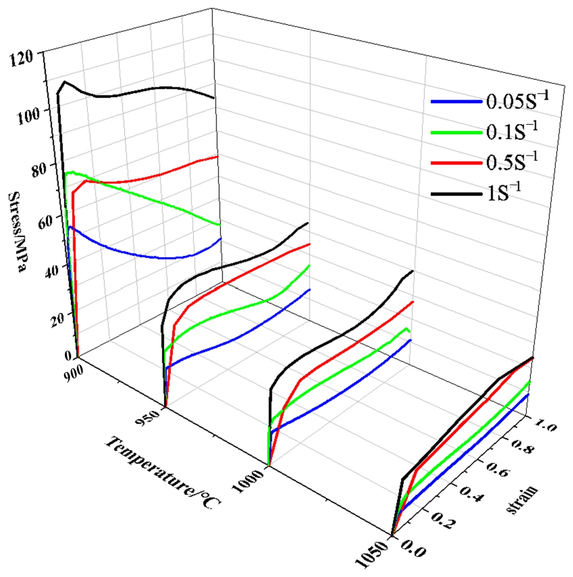
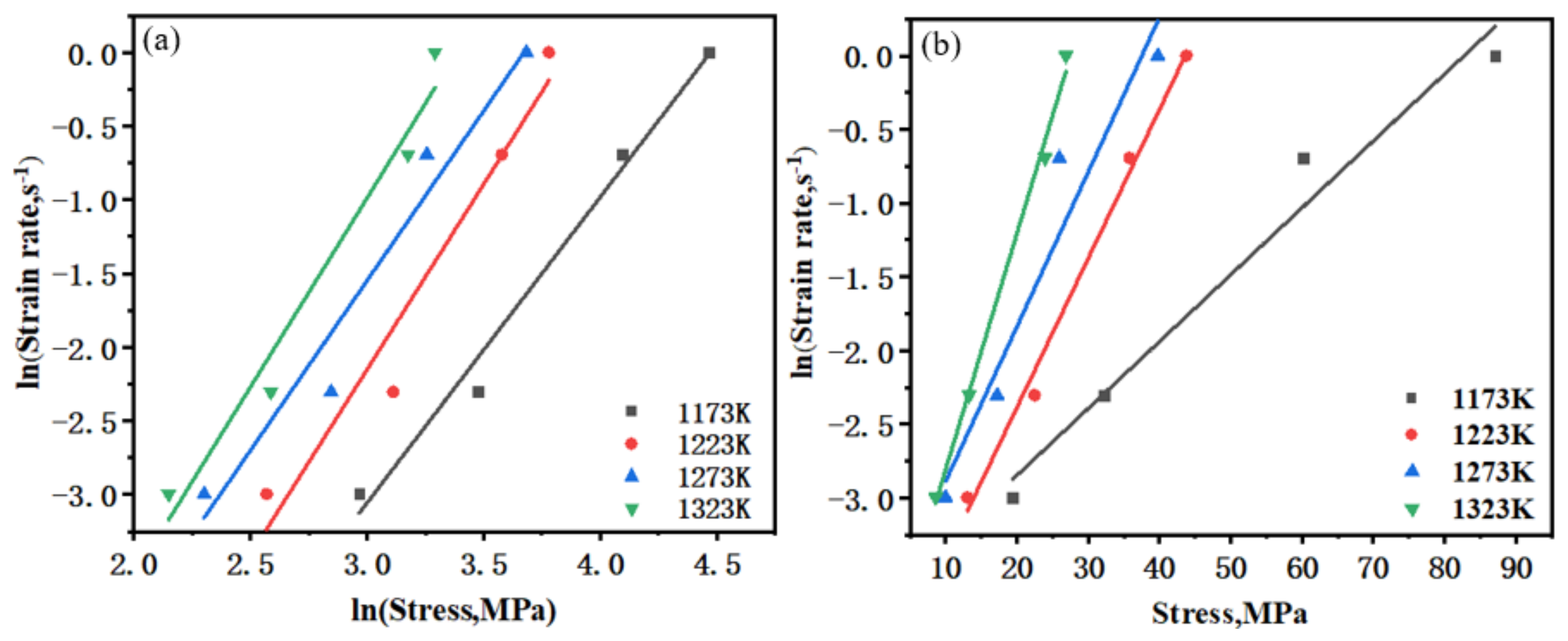
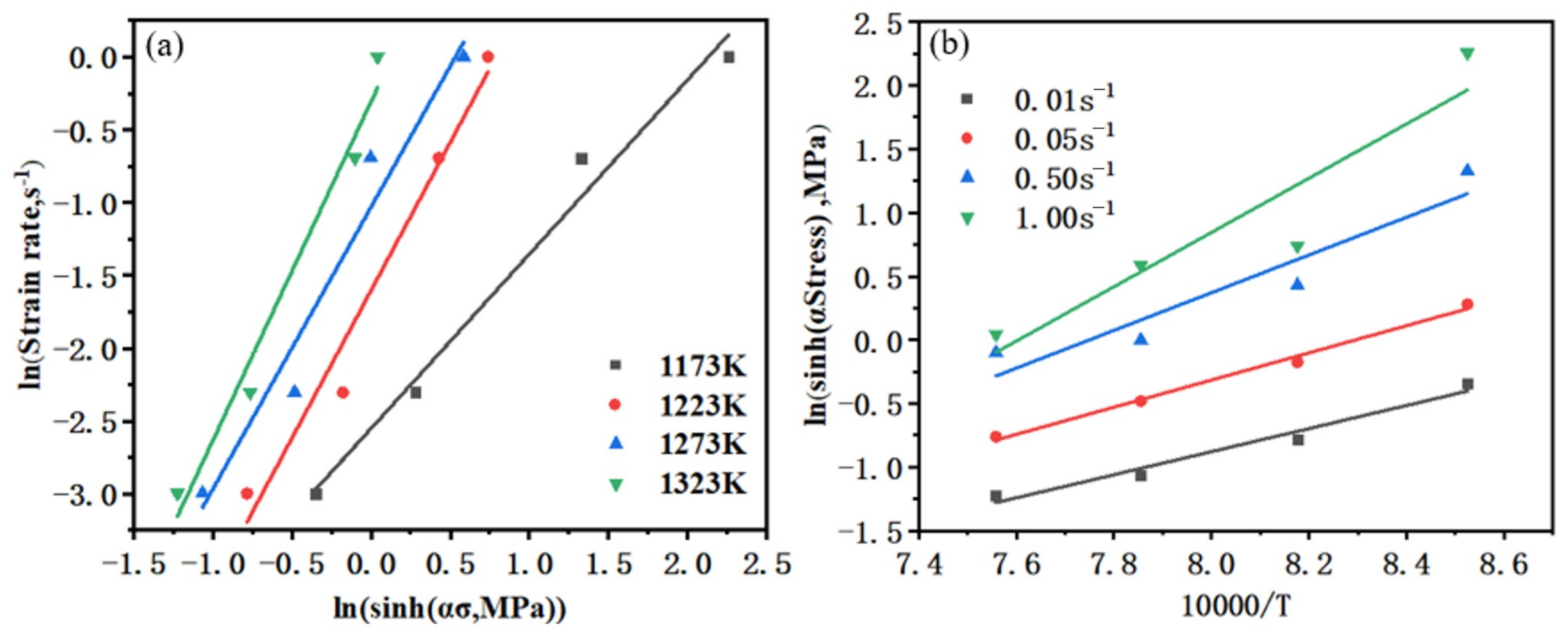
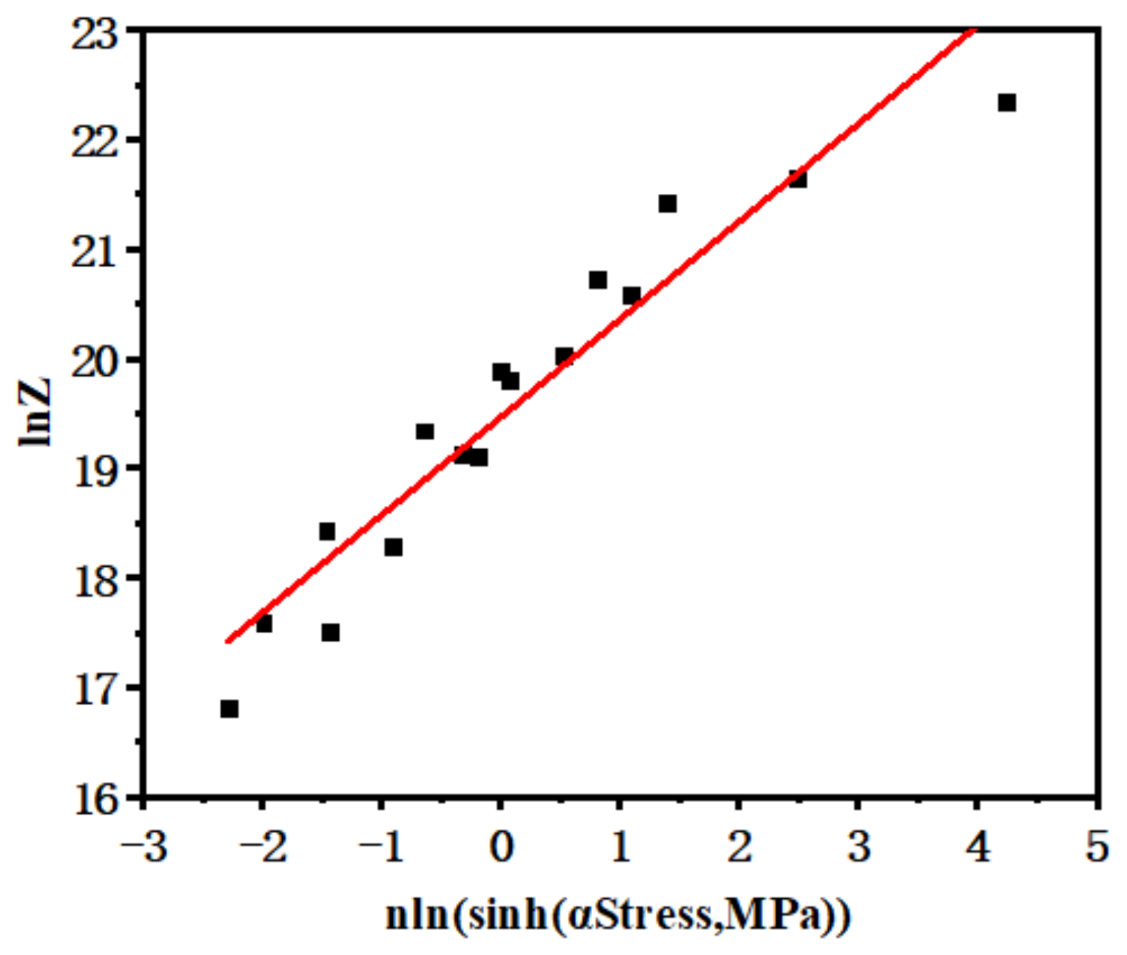
2.2. The Material Model of Ti80 Alloy

The hyperbolic sinusoidal form of the Arrhenius equation could describe the strain characteristics of different strains, strain rates and temperatures [24]. The Arrhenius material model is as follows:
(1)
Low stress stage (ασ < 0.8):
ε · = A 1 σ n 1 e x p ( Q R T )
(2)
High stress stage (ασ > 0.8):
ε · = A 2 e x p ( β σ ) e x p ( Q R T )
(3)
Whole stress range:
ε · = A [ s i n ( α σ ) ] n e x p ( Q R T )
where A1, A2, A, n1, n, α and β represent constants independent of the deformation temperature; α = β/n1; R represents the gas constant, ~8.314 J/mol·K−1; T represents the deformation temperature (K); Q represents the deformation activation energy (J/mol); σ represents the flow stress corresponding to the stress variable. For the piercing process of titanium alloy seamless tubes, the flow stress was relatively low at the rolling start stage. During the final rolling stage, the flow stress increased due to the decrease in temperature for titanium alloy. Therefore, the logarithms of (1) and (2) could be obtained as:
ln ε · = ln A 1 + n 1 ln σ Q R T
ln ε · = ln A 2 + β σ Q R T
Next, the partial derivative of Equation (4) was calculated as:
n 1 = ln ε · ln σ
β = ln ε · σ
where n1 and β are the average values of the slope for the ln ε · − lnσ (Figure 3a) and ln ε · − σ (Figure 3b) curves, respectively. According to Figure 3, n1 = 2.366, β = 0.0801 and α = β/n1 = 0.0339.
The logarithms of both sides of Equation (3) are calculated:
ln ε · = ln A + n lnsinh ( α σ ) Q R T
The deformation activation energy Q could be calculated as:
Q = R [ ln ε · l n sin h α σ ] T [ l n sin h α σ 1 / T ] ε ·
Equation (9) could be simplified as:
n = [ ln ε · l n sin h α σ ] T
S = [ l n sin h α σ 1 / T ] ε ·
So, the deformation activation energy Q could be calculated as:
Q = R n S
According to Equations (10) and (11), n and S are the average values of the slope for the ln ε · − lnsinh(ασ) (Figure 4a) and lnsinh(ασ) − 1/T curves (Figure 4b), respectively. Therefore, n = 1.875, S = 13,974.775 and Q = RnS = 217,849 J/mol.
In order to build the material model for titanium alloy, the compensation factor Z is calculated as:
Z = ε · exp ( Q R T ) = A [ lnsinh ( α σ ) ] n
The logarithm of (13) could be obtained as:
ln Z = ln A + n   lnsinh ( α σ )
where lnA is the intercept of the lnZ-nlnsinh(ασ) curve, as shown in Figure 5. According to Equation (14), A = 2.838 × 10⁸. The values of A, α, n and Q were assigned to Equation (3); the material model of Ti80 titanium alloy was calculated as:
ε · = 2.838   ×   10 8   ×   [ sinh ( 0.0339 σ ) ] 1.875 exp ( 217849 R T )
The constitutive equation data were input into DEFORM-3D (SFTC Inc., Toronto, ON, Canada) to determine the plastic flow stress of Ti80 alloy, as shown in Figure 6. In order to obtain more accurate results of temperature parameters, it cannot be empirically considered that about 90% of plastic work is converted into heat [25,26]. The integral expression of the work heat conversion coefficient βint is as shown [27,28]:
β i n t = ρ C Δ T / d W p
where ρ is the density of the material; C is the specific heat capacity of the material; ∆T is the temperature rise; WP is the plastic deformation work; d is the Taylor Quinney coefficient [29]. Density, specific heat and temperature rise in plastic deformation of materials determined the proportion of plastic work converted into heat. The real-time temperature change of Ti80 alloy during compression deformation was obtained through thermal simulation compression experiments. When the strain rate is 1, the initial heating temperatures are 850 °C, 950 °C and 1050 °C, the ratio of plastic work to heat are βint(850°C) = 7.92%, βint(950°C) = 90.59% and βint(1050°C) = 3.19%, respectively. In compression experiments, the temperature of Ti80 alloy increased by 8.76 °C, 42.95 °C and 2.2 °C after deformation at 850 °C, 950 °C and 1050 °C, respectively. Ti80 alloy approached its β-Ti transformation point (~935 °C) at 950 °C. Therefore, the deformation energy of Ti80 was mainly stored as thermal energy at the deformation at 950 °C.

2.3. The FE Simulation and Characterization of Cross-Rolling Perforation

In this study, two-roll cross-rolling perforation was applied. A 3D model was designed according to the two-roll piercing machine and then imported into DEFORM-3D commercial code. The 3D models are shown in Figure 7. After the blank was bitten in, the blank rotated in the opposite direction with the roll with the same rotation direction due to the existence of a feeding angle and a rolling angle. Relevant parameters of the simulation are shown in Table 2, Table 3 and Table 4. The FE model was divided by tetrahedral mesh elements. The minimum length of mesh elements was 1 mm, and these were mainly located on the curved surfaces and corners of the model. The maximum length of mesh elements was 5 mm, and these were mainly located in center of the model. The number of elements was 172,480. When the plastic deformation of the mesh elements in DEFORM-3D exceeded 30%, the mesh elements would be automatically subdivided and refined. Therefore, the mesh elements were automatically refined at any time during the simulation process, which indicated that the simulation results were not sensitive to the initial mesh refinement. The friction coefficient was set from the hot-working friction model embedded in DEFORM-3D, which was consistent with previous hot-rolling friction models [20,24]. The test data of FE simulation consisted of diameter, wall thickness, stress and roll load. The diameter and wall thickness indicated the manufacturing accuracy of Ti80 seamless tubes. The stress and roll load indicated the requirements for equipment capabilities.
According to the FE simulation results, Ti80 seamless pipes were subjected to actual perforation experiments using optimized process parameters. Then, the microstructure and mechanical properties of the seamless pipes were analyzed. Metallographic samples were prepared in accordance with standards. The microstructure was characterized using optical microscopy (OM). The tested blocks of suitable length and width having longitudinal through-thickness orientations were cut from Ti80 seamless tubes for tensile and Charpy tests. Tensile specimens with a gauge length of 25.0 mm and a diameter of 6.25 mm were processed. The tensile tests were performed on an MTS machine with a speed of 0.25 mm/min. Impact specimens with the size of 10 × 10 × 55 mm3 were processed. The Charpy V-notch impact test was measured using a drop-weight impact tester at −10 °C. The data were measured five times and the average value was calculated.

3. Results and Discussion

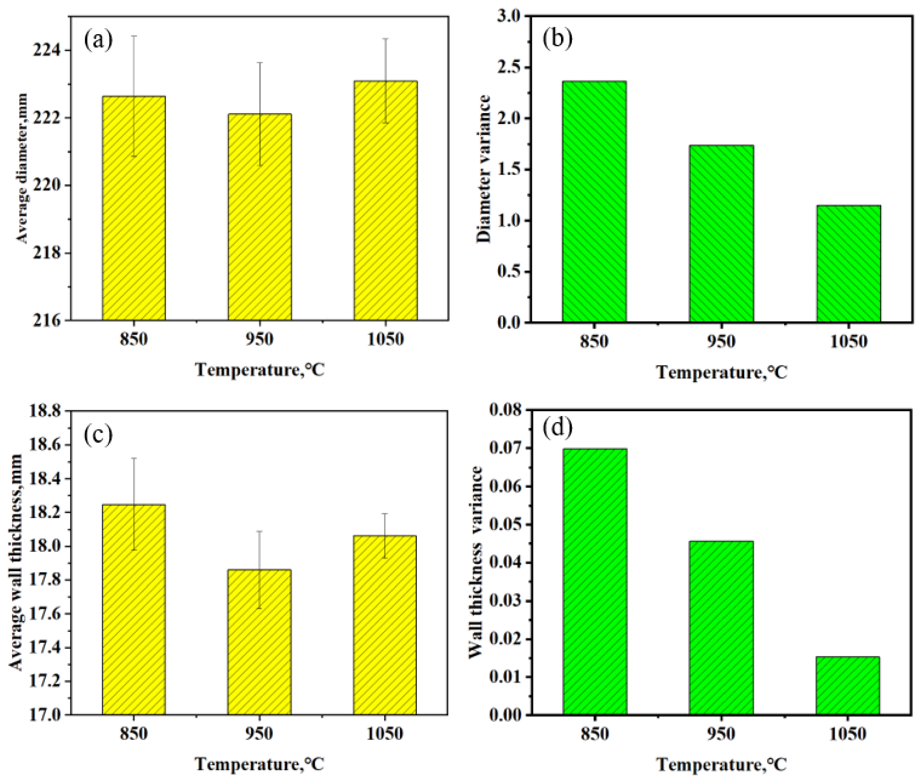
3.1. The Effect of Piercing Temperature on Capillary Size

The accuracy of size was the most important aspect that directly reflected the quality of seamless tubes. Therefore, it was necessary to extract and measure the size of the simulated tubes. After simulation, 3D models of the tubes were imported into the 3D software to draw the part drawings. Then, they were measured and we obtained cross-sectional views of the sections under different deformation temperatures of 850 °C, 950 °C and 1050 °C, as shown in Figure 8. The selected locations of interface data points are shown in Figure 9. The diameters and wall thicknesses of tubes were taken from point P1 to point P8, as shown in Table 5 and Table 6, respectively.
According to Table 4, the average diameters of 850 °C, 950 °C and 1050 °C stable threading stages were 222.64 mm, 222.11 mm and 223.09 mm, respectively; the variance values of the diameters were 2.365, 1.735 and 1.152, respectively. The average wall thicknesses were 18.24 mm, 17.86 mm and 18.06 mm, respectively. The variance values of the wall thickness were 0.0698, 0.0457 and 0.0153, respectively. As shown in Figure 10, the variance value decreased rapidly with the increase in temperature, indicating that the increase in temperature improved the dimensional uniformity of the capillaries significantly. Threaded at 1050 °C, the dimensional stability of the tubes was the best. The diameter and wall thickness were both relatively uniform. Combined with the stress ratio histogram in Figure 11, the stress decreased during processing with the increase in temperature. Moreover, the stress value distribution was more uniform, which reduced the fluctuation of load and contributed to the uniformity of capillary size. Due to the contact heat exchange between the rolling roller and seamless tube, the uneven deformation in the initial stage of deformation was relatively obvious. The increase in perforation temperature reduced the temperature difference between the surface and core of seamless tubes, significantly improving deformation uniformity. It was also beneficial for reducing the generation of additional and residual stresses.

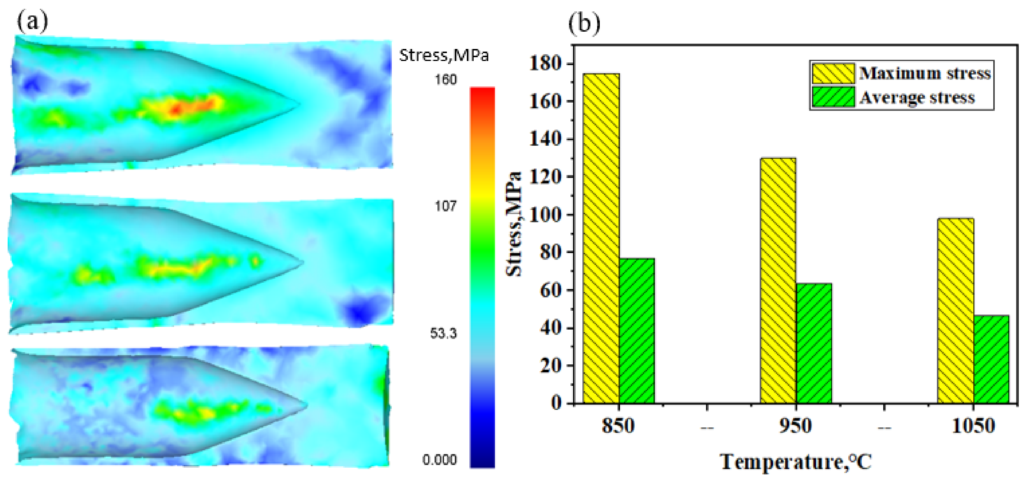
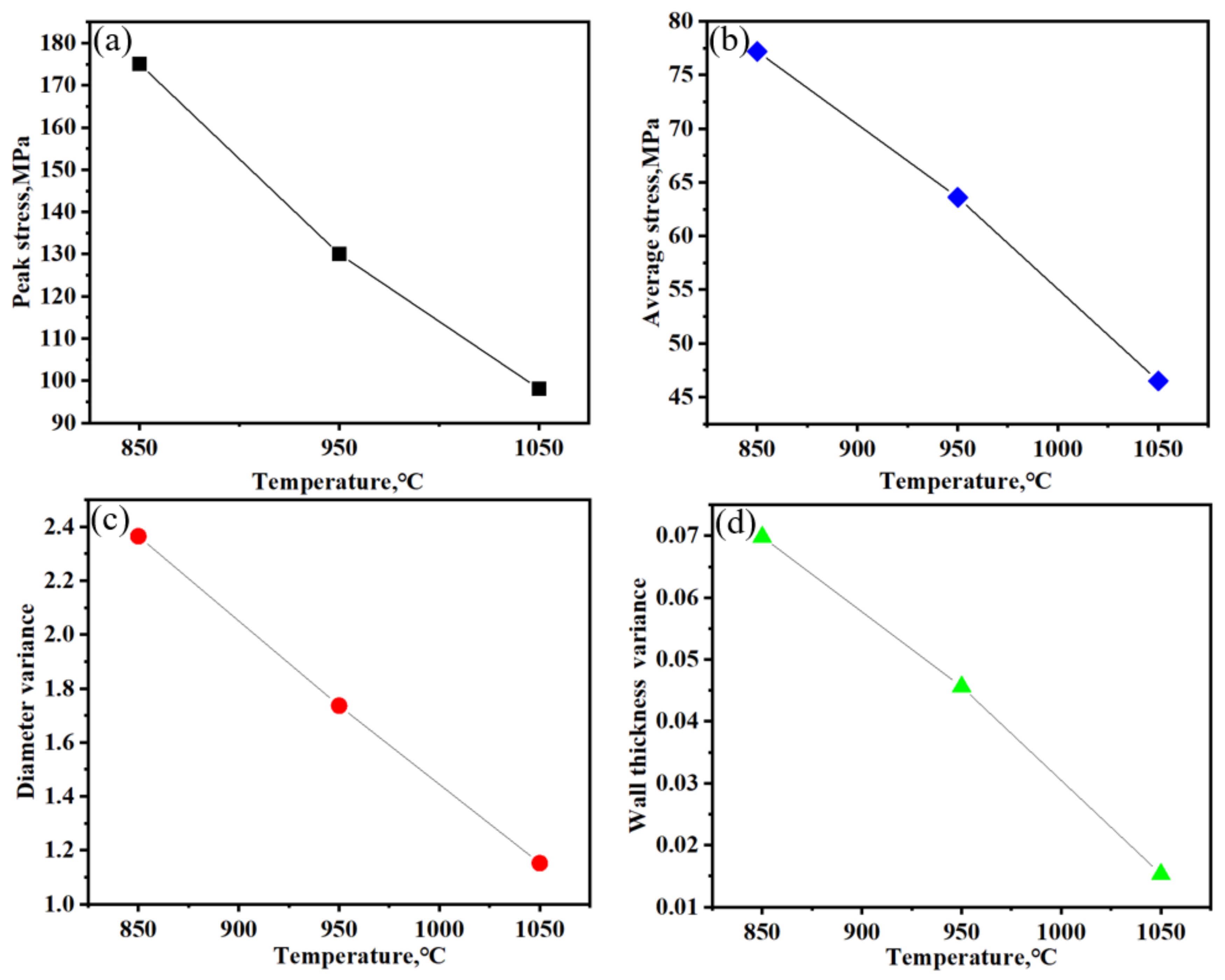
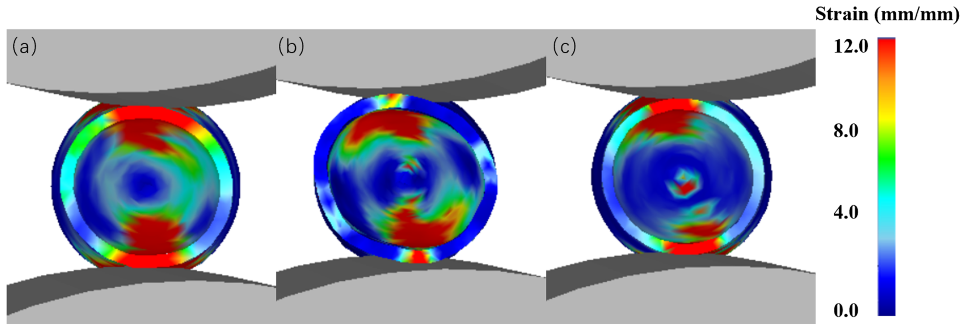
3.2. The Effect of Piercing Temperature on Stress Distribution

The stress field could reflect the excellence of processing technology. Based on the FE simulation, the change in stress fields in the processing process was extracted to reflect the state of the tube blank during processing.
Figure 11a,d,g show cloud diagrams of equivalent stress field distribution at times of 0.5–20 s at temperatures of 850 °C, 950 °C and 1050 °C, respectively. Histograms of the stress ratios at 8 s and 16 s of 850 °C, 950 °C and 1050 °C are shown in Figure 11b, Figure 11c, Figure 11e, Figure 11f, Figure 11h and Figure 11i, respectively. According to the distribution of stress fields, the stress reached its peak at the roll contact line and gradually decreased to both sides. The peak stress line improved with the increment of time and entered the stable rolling section. The stress value in the biting stage was 20 MPa higher than that in the stable perforation section. Figure 11b,c show that the stress at 850 °C was mainly distributed in the 50–120 MPa range. As the temperature increased to 950 °C, the overall stress decreased obviously. Meanwhile, the distribution of the stress was more concentrated, mainly in the 30–50 MPa range, as shown in Figure 11e,f. According to Figure 11h,i, the stress in the rolling process of the tube blank was the smallest at 1050 °C. The main range of stress was 10–30 MPa. The stress was mainly concentrated near the contact with the roll. With the increase in temperature, the overall stress range gradually decreased. The mechanical fluctuation caused by uneven stress in processing gradually decreased. The load of piercing processing decreased, which contributed to the uniformity in the processing area and processed capillary size.
Figure 12a,b show the peak and average stresses at 850 °C, 950 °C and 1050 °C at the perforation stable section, respectively. With the increment in temperature, the peak stress and average stress decreased steadily. Combined with Figure 10b,d, the variation in diameter variance and wall thickness variance with temperature were the same as in the stable rolling section. The variance between diameter, wall thickness, peak stress and average stress with different temperatures in the stable section of perforation were both linear, as shown in Figure 13a, Figure 13b, Figure 13c and Figure 13d, respectively. Figure 14a–c show the distribution of strain rates on the cross-section of Ti80 seamless tubes at the piercing process at 850 °C, 950 °C and 1050 °C. The overall distribution of strain rates at piercing temperatures in a range of 850–1050 °C was similar. The strain was concentrated at the contact point between the seamless tube and roller, gradually decreasing from the center to both sides. The peak strain rates at the piercing of 850 °C, 950 °C and 1050 °C were 7.7 s−1, 9.1 s−1 and 12.9 s−1, respectively. As the temperature increased, the binding force between atoms weakened, resulting in the decrease in critical shear stress. β-Ti transformation led to an increase in slip systems, which improved the plasticity of the titanium alloy.

3.3. The Effect of Piercing Temperature on Rolling Load

In the process of cross-rolling perforation, the load of the roll and the axial force of the plug determined the dimensional accuracy. The average load of the upper and lower rollers of the piercer was extracted and sorted out using simulation. As shown in Figure 15a, the rolling force decreased to a certain extent, and the distribution of the rolling force tended to be stable with the increase in temperature. The increment of the initial temperature of the blank reduced the requirements for the rolling mill. Moreover, it reduced the loss of the rolling mill’s roll, which was more suitable for production and processing.
Compared with theoretical calculations of the axial force of the plug, the FE simulation extraction was more simplified [11]. The average axial force of the ejector extracted and sorted is shown in Figure 15b. With the increase in temperature, the axial force of the ejector showed a downward trend. At this time, the axial force on the ejector rod decreased, which reduced the bending of the ejector rod. Because the ejector rod rotated with the tube blank, the most ideal state was that the ejector rod did not produce any bending. Therefore, the bending of the ejector rod was the smallest at 1050 °C. There, the uniformity of the wall thickness of the crude tube was better than at 850 °C and 950 °C. Combined with the ratio axial force of the plug and the roll load (Q/P), the reduction in the Q/P value decreased the axial sliding in the process of threading.
The range of Q/P measured for the conical two-roll piercer was 0.32–0.40 [30]. According to the results of the calculation, the Q/P values of 850 °C, 950 °C and 1050 °C were 0.430, 0.377 and 0.314, respectively. Therefore, serious axial sliding occurred at 850 °C, and axial sliding occurred directly. The occurrence of axial sliding in the process of cross-rolling perforation has an adverse impact on the quality of wool tube and piercers, which reduced the production efficiency, aggravated the wear of roll and produced unnecessary energy consumption. Moreover, it made scratches appear on the inner and outer walls of the capillary, which affected the accuracy of the dimensions. The Q/P values of 950 °C and 1050 °C were both in reasonable ranges. The Q/P was the smallest at 1050 °C, which was conducive to the force and energy conditions of perforation.
According to the capillary dimensional accuracy, stress nephogram analysis, roll-rolling force analysis and temperature change law in the stable stage of threading-rolling, threading at 1050 °C was better. If the initial temperature continued to rise to more than 1050 °C, the β-Ti grains coarsened, which led to a decrease in plastic district organization. Meanwhile, the increment in the temperature led to obvious softening of Ti80 alloy, which was not conducive to the continuation of the cross-rolling piercing process. If the temperature was too high, the inner wall was oxidized seriously during the process of threading, which significantly reduced the quality of the penetrating capillary. Therefore, 1050 °C was more suitable for titanium tube perforation than 850 °C or 950 °C.

3.4. Experimental Verification of Piercing for Ti80 Seamless Tubes

Through the FE simulation perforation experiment, the temperature parameters were optimized. Then, a cross-rolling perforation experiment under the same conditions was carried out. The results showed that the Ti80 titanium alloy seamless tube met the requirements successfully. The Ti80 titanium alloy for the cross-rolling perforation experiment was provided by the Tianjin steel tube company. The raw material is shown in Figure 16a. The size of the raw material was Φ210 mm × 1500 mm. The head and tail of the blank were drilled with centering holes, as shown in Figure 16b. The size of the rear centering hole was Φ50 mm × 85 mm. The surface of the tube blank was coated with thermal insulation coating on site. The plugs were pre-coated with glass lubricant. The total furnace time was 7.5 h, including 4 h at 850 °C, one hour at 980 °C and 2.5 h at 1050 °C. Through the cross-rolling piercing experiment, the seamless tube of Ti80 titanium alloy was successfully pierced, as shown in Figure 17.
The microstructure of the Ti80 tubes is shown in Figure 18. According to the high magnification diagram (Figure 18b), the microstructure of Ti80 tubes consisted of layered α-Ti, grain boundary β-Ti and a Widmannstatten structure. Because the heating temperature of the initial blank for cross-rolling perforation was higher than the β-Ti transformation temperature, the whole cross-rolling perforation process was always in the single β-Ti region. After perforation, β-Ti grains were obviously refined due to the original deformation of the tube blank under high temperatures. Large deformed α-Ti transformed into β-Ti; dynamic recrystallization and dynamic recovery occurred, which contributed to a smaller size of β-Ti grains. The strength and toughness of Ti80 tubes are shown in Table 7. The yield and tensile strength of Ti80 tubes were 692 ± 9 MPa and 867 ± 2 MPa, respectively. The elongation was 7 ± 1%. The absorbed energy at −10 °C was 52 ± 6 J. The strength and toughness of the Ti80 seamless tube were improved by the refinement of the prior β-Ti grains and formation of α-Ti layers.

4. Conclusions

In this study, the effect of piercing temperature on the deformation mechanism, stress–strain distribution and dimensional accuracy of Ti80 titanium alloy seamless tubes was studied based on an FE simulation. By adjusting the piercing temperature, the accuracy of the diameter and thickness for titanium alloy seamless tubes was optimized. Moreover, Ti80 titanium alloy seamless tubes with a good balance of strength–toughness were obtained through actual perforation experiments.
(1)
The plastic work transformed into the proportions of heat of Ti80 titanium alloy were 7.92%, 90.59% and 3.19% for 850 °C, 950 °C and 1050 °C, respectively. At the cross-rolling piercing process, the friction heat generation was the only factor affecting the temperature at 1050 °C. At 950 °C, most plastic work transformed into heat quantity, which affected the processing temperature.
(2)
In the stable perforation section, the peak stress, average stress, diameter variance and wall thickness variance of the blank showed linear downward trends with an increase in temperature. As the temperature increased, the roll load and axial force of the plug decreased, which improved the dimensional accuracy of the seamless tubes.
(3)
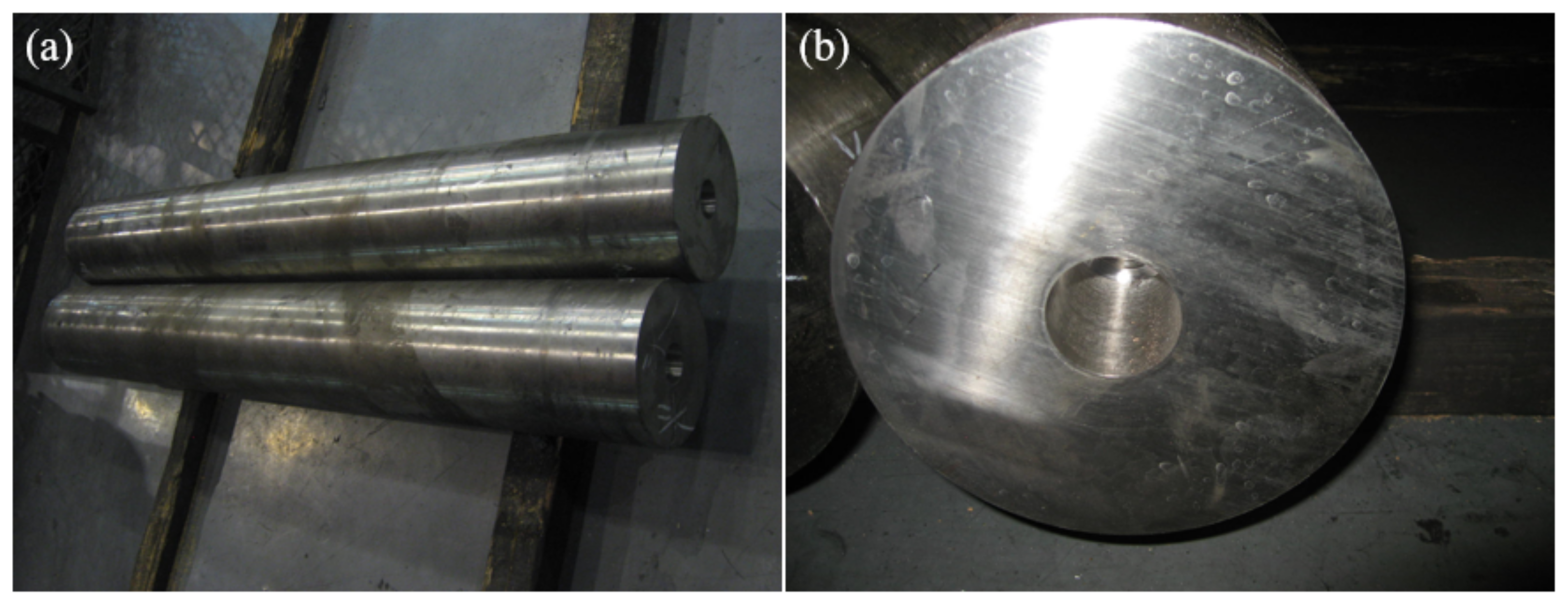
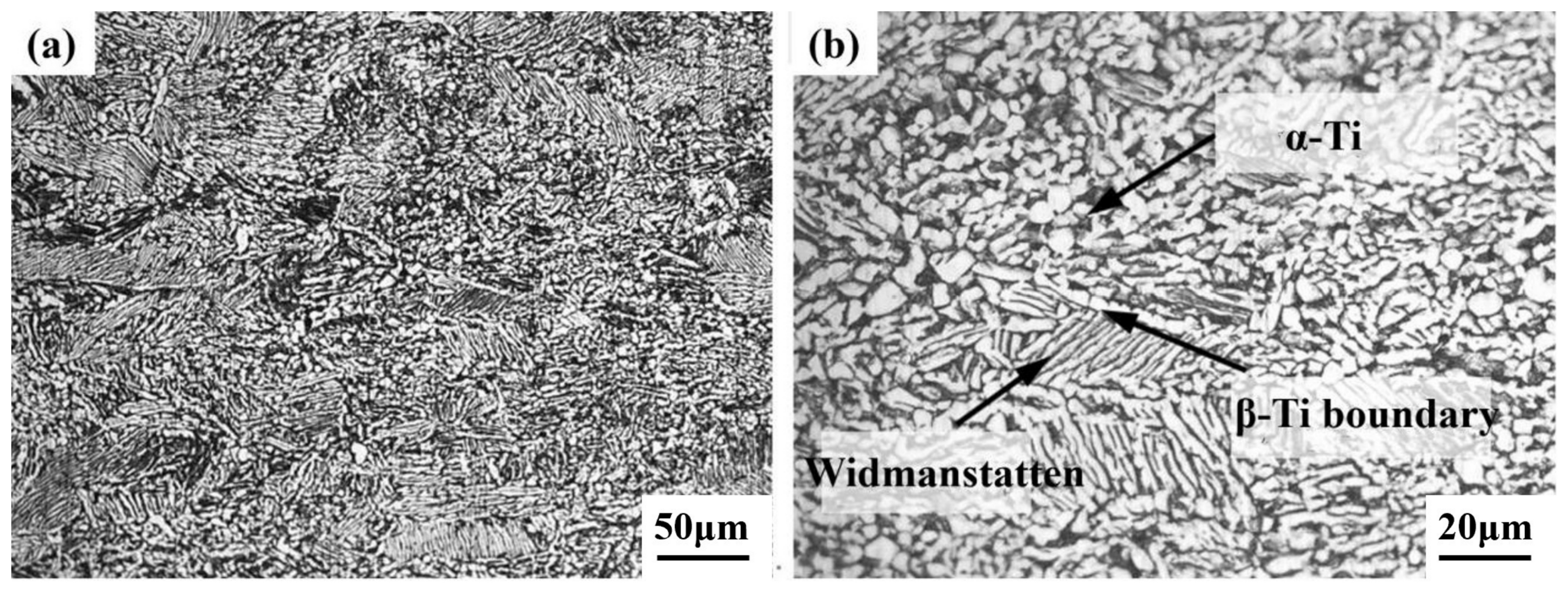
Based on the FE simulation, the threading experiment of Ti80 seamless tubes was successfully processed at the initial temperature of 1050 °C. The microstructure of the tubes was layered α-Ti, grain boundary β-Ti and a Widmannstatten structure. The tensile strength, yield strength and absorbed energy were 867 MPa, 692 MPa and 52 J, respectively.

Author Contributions

Writing—original draft, X.Z.; writing—review and editing, W.F.; data curation, C.L.; conceptualization, F.C.; methodology, F.C. All authors have read and agreed to the published version of the manuscript.

Funding

This study was financially supported by the National Key Research and Development Program of China (2021YFB3700802).

Institutional Review Board Statement

Not applicable.

Informed Consent Statement

Not applicable.

Data Availability Statement

The data that support the findings of this study are available from the corresponding author upon reasonable request.

Conflicts of Interest

X.Z. and C.L. are members of Tianjin Pine Co., Ltd. Other authors declare no conflict of interest.

References

  1. Quan, S.; Song, K.; Zhang, B.; Wang, Q.; Zheng, K.H.; Zhang, D.D. Effect of heat treatment process on microstructure of Ti80 alloy. Trans. Mater. Heat Treat. 2018, 39, 44–52. [Google Scholar]
  2. Pumpyanskiy, D.A.; Illarionov, A.G.; Vodolazskiy, F.V.; Kosmatskiy, Y.I.; Popov, A.A. Promising Titanium Alloys for Cold-Worked Pipe Manufacture. Metallurgist 2023, 67, 1–16. [Google Scholar] [CrossRef]
  3. Qinyang, Z.; Qiaoyan, S.; Shewei, X.; Yongnan, C.; Cong, W.; Huan, W.; Jianwei, X.; Mingpan, W.; Weidong, Z.; Yongqing, Z. High-strength titanium alloys for aerospace engineering applications: A review on melting-forging process. Mater. Sci. Eng. A 2022, 845, 143260. [Google Scholar]
  4. Peng, X.; Yu, H.; Lian, Z.; Zhang, Q. Experimental and theoretical study on the mechanical properties of titanium alloy drill pipe in short radius and long horizontal wells. J. Braz. Soc. Mech. Sci. Eng. 2021, 43, 416. [Google Scholar] [CrossRef]
  5. Yan, S.; Song, G.-L.; Li, Z.; Wang, H.; Zheng, D.; Cao, F.; Horynova, M.; Dargusch, M.S.; Zhou, L. A state-of-the-art review on passivation and biofouling of Ti and its alloys in marine environments. J. Mater. Sci. Technol. 2018, 34, 421–435. [Google Scholar] [CrossRef]
  6. Yu, Z.Y.; Yu, Z.T.; Liu, H.Y. Research and application status of titanium alloy seamless tube. Hot Work. Process 2018, 47, 6–9. [Google Scholar]
  7. Liu, W.; Zhang, Y.B.; Hou, Z.J. Research status of rolling process for titanium and titanium alloy tubes. Metal World 2019, 6, 5–7. [Google Scholar]
  8. Choi, B.-J.; Moon, I.Y.; Oh, Y.-S.; Kang, S.-H.; Kim, S.-J.; Jung, J.; Kim, J.-H.; Kim, D.-K.; Lee, H.W. Die Design for Extrusion Process of Titanium Seamless Tube Using Finite Element Analysis. Metals 2021, 11, 1338. [Google Scholar] [CrossRef]
  9. Li, G.; He, Z.; Ma, J.; Yang, H.; Li, H. Springback Analysis for Warm Bending of Titanium Tube Based on Coupled Thermal-Mechanical Simulation. Materials 2021, 14, 5044. [Google Scholar] [CrossRef]
  10. Wei, D.; Chen, Y.; Li, H.; Yang, J. Residual stress evolution and tailoring of cold pilgered Ti-3Al-2.5V tube. Int. J. Mech. Sci. 2022, 225, 107366. [Google Scholar] [CrossRef]
  11. He, S.; Zeng, W.; Zhao, Z.; Xu, J.; Zhou, D. Analysis of anisotropy mechanism in relation with slip activity in near α titanium alloy pipe after Pilger cold rolling. J. Alloys Compd. 2022, 909, 164785. [Google Scholar] [CrossRef]
  12. Shuang, Y.H.; Wang, F.J.; Wang, Q.H. Exploration of Continuous Cross Rolling Technology and Equipment for Seamless Steel tube. J. Mech. Eng. 2017, 53, 18–24. [Google Scholar] [CrossRef]
  13. Jie, W.F.; Hua, S.Y.; Hua, H.J.; Qing, W.; Chao, S.J. Explorative study of tandem skew rolling process for producing seamless steel tubes. J. Mater. Process. Technol. 2014, 214, 8. [Google Scholar]
  14. Dai, G.; Cui, Y.; Zhou, D.; Guo, Y.; Chang, H.; Zhou, L. Hot Deformation Behavior and Mechanistic Understanding of New TF400 Titanium Alloy. Metals 2019, 9, 1277. [Google Scholar] [CrossRef]
  15. Zhang, Y.Q.; Zhan, M.; Fan, X.G.; Yang, K. Formig of pure titanium tubes by combined spinning-ultrasonic surface rolling process: Microstructure and mechanical properties. J. Manuf. Process. 2023, 105, 70–83. [Google Scholar] [CrossRef]
  16. Zhou, D.D.; Zeng, W.D.; Xu, W.J. Process Analysis of Ti80 Alloy Seamless tube Preparation by Cross Rolling Perforation Method. Rare Metal Mater. Eng. 2020, 49, 1045–1050. [Google Scholar]
  17. Ding, X.F.; Shuang, Y.H.; Wang, Q.H. AZ31 Research on the New Process of Skew Rolling Perforation for Magnesium Alloy Seamless tube. Rare Metal Mater. Eng. 2018, 47, 357–362. [Google Scholar]
  18. Shi, J.; Yu, W.; Dong, E.; Wang, J. Finite element simulation for hot continuous-rolled TC4 alloy seamless pipe. Adv. Mater. Process. 2018, 18, 705–716. [Google Scholar]
  19. Ebrahimi, M.; Tabei, K.H.; Naseri, R.; Djavanroodi, F. Effect of flow-forming parameters on surface quality, geometrical precision and mechanical properties of titanium tube. J. Process. Mech. Eng. 2017, 232, 702–708. [Google Scholar] [CrossRef]
  20. Chen, C.; Chen, J.; Shuang, Y.; Li, C. Short-Flow Rolling Process and Heat Treatment of Seamless Titanium Alloy Tube. Metals 2023, 13, 527. [Google Scholar] [CrossRef]
  21. Romancev, B.A.; Goncharuk, A.V.; Aleshchenko, A.S.; Gamin, Y.V. Production of hollow thick-walled profiles and pipes made of titanium alloys by screw rolling. Russ. J. Non-Ferrous Met. 2015, 56, 522–526. [Google Scholar] [CrossRef]
  22. Li, C.; Shuang, Y.; Chen, J.; Zhou, Y.; Wang, C.; Chen, C.; Guo, Y.; Dong, B. Research on the impact of mandrels in titanium tubes during tube continuous rolling. Mater. Res. Express 2023, 10, 086512. [Google Scholar] [CrossRef]
  23. Radionova, L.V.; Lisovskiy, R.A.; Sarafanov, A.E.; Faizov, S.R.; Erdakov, I.N. Analysis of deformation behavior for titanium alloys at elevated temperature. In Proceedings of the 9th International Conference on Industrial Engineering, Sochi, Russia, 26–28 May 2023; pp. 800–809. [Google Scholar]
  24. Muhammad, I.S.; Can, L.; Lihui, L.; Yingjian, G.; Ali, M.H.; Fazal, H.; Sergei, A.; Jun, J.; Huijing, H. An investigation into Arrhenius type constitutive models to predict complex hot deformation behavior of TC4 alloy having bimodal microstructure. Mater. Today Commun. 2022, 31, 103622. [Google Scholar]
  25. Mou, Y.; Lian, Z.; Li, W.; Zhong, X.; Li, J.; He, Y.; Cao, J.; Eliaz, N. The effect of friction welding on the mechanical properties and corrosion fatigue resistance of titanium alloy drill pipe. Fatigue Fract. Eng. Mater. Struct. 2021, 45, 466–481. [Google Scholar] [CrossRef]
  26. Wu, D.-S.; Huang, J.-L.; Kong, L.; Hua, X.-M.; Wang, M.; Li, H.; Liu, S.-T. Numerical analysis of arc and molten pool behaviors in high speed tandem TIG welding of titanium tubes. Trans. Nonferrous Met. Soc. China 2023, 33, 1768–1778. [Google Scholar] [CrossRef]
  27. Liu, Q.; Tong, K.; Zhu, G.-C.; Tan, Y.; Zhang, J.; Xu, X.; Li, X.; Song, S.-Y. Investigation of fracture causes of the titanium alloy drill pipe in ultra-short radius horizontal well drilling. Eng. Fail. Anal. 2022, 140, 106516. [Google Scholar] [CrossRef]
  28. Aghabeyki, F.; Mirnia, M.J.; Elyasi, M. Cold and warm flaring of thin-walled titanium tube using single-point incremental forming. Int. J. Adv. Manuf. Technol. 2021, 114, 3357–3376. [Google Scholar] [CrossRef]
  29. Kosmatsky, Y.I.; Barichko, B.V.; Fokin, N.V.; Nikolenko, V.D. Application of the Gleeble 3800 system in developing hot pipe extrusion and pipe end upsetting technoligies. Metallurgist 2021, 65, 404–411. [Google Scholar] [CrossRef]
  30. Zhou, D.D.; Zeng, W.D.; Xu, W.J. Temperature prediction of new titanium alloy cross rolling perforation based on machining diagram. Rare Metal Mater. Eng. 2019, 48, 2531–2536. [Google Scholar]
Figure 1. Diagram of a hot compression sample (mm).
Metals 13 01893 g001
Figure 2. True stress–strain curve of Ti80 alloy under different deformation conditions.
Metals 13 01893 g002
Figure 3. Curves of ln ε · − lnσ (a) and ln ε · − σ (b).
Metals 13 01893 g003
Figure 4. Curves of ln ε · − lnsinh(ασ) (a) and lnsinh(ασ) − 1/T (b).
Metals 13 01893 g004
Figure 5. Curve of lnZ − lnsinh(ασ).
Metals 13 01893 g005
Figure 6. Plastic flow stress parameters of Ti80 alloy in material library.
Metals 13 01893 g006
Figure 7. The 3D model (a) and import model (b) in DEFORM-3D.
Metals 13 01893 g007
Figure 8. Cross-section of a simulated extraction.
Metals 13 01893 g008
Figure 9. Selection of measurement data points.
Metals 13 01893 g009
Figure 10. Average diameter of capillaries (a), diameter variance (b), average wall thickness of capillaries (c) and wall thickness variance (d) under different temperatures.
Metals 13 01893 g010
Figure 11. Cloud diagrams of equivalent stress field distribution at 0.5–20 s and histograms at 8 s and 16 s stress ratio under 850 °C (ac), 950 °C (df) and 1050 °C (gi).
Metals 13 01893 g011aMetals 13 01893 g011bMetals 13 01893 g011c
Figure 12. Peak (a) and average stress (b) of tubes at perforated stable sections.
Metals 13 01893 g012
Figure 13. Point line diagram of peak stress (a), average stress (b), diameter variance (c) and wall thickness variance (d) under different temperatures at perforated stable sections.
Metals 13 01893 g013
Figure 14. Distribution of strain rate on the cross-section of Ti80 seamless tubes: (a) 850 °C; (b) 950 °C; (c) 1050 °C.
Metals 13 01893 g014
Figure 15. Average roll (a) and plug axial load (b).
Metals 13 01893 g015
Figure 16. Ti80 tube blank bar (a) and its entering hole (b).
Metals 13 01893 g016
Figure 17. Tube blank discharge (a) and capillary perforation (b).
Metals 13 01893 g017
Figure 18. Microstructure of a Ti80 seamless tube at low (a) and high magnification (b).
Metals 13 01893 g018
Table 1. Isothermal constant strain rate thermal compression test scheme.
Test ParametersNumerical Value
Test temperature/°C900, 950, 1000, 1050
Strain rate/s−10.05, 0.10, 0.5, 1.0
Total deformation60%
Heating rate °C/s10
Holding time/s60
Table 2. Simulation process parameter variables.
Process ParametersNumerical Value
Initial temperature of tube blank/°C850, 950, 1050
Ratio of plastic work to heat βint7.92%, 90.59%, 3.19%
Table 3. Relevant parameters of the cross-rolling piercing process.
Process ParametersNumerical Value
Billet diameter Rd/mm210
Tube blank length L1/mm150
Plug diameter Rd/mm166
Ejector rod diameter R0/mm163.9
Feed angle α9
Rolling angle β15
Roll speed nd/rpm82.35
Speed of guide plate nd/rpm24.22
Head extension L2/mm75
Roll distance L3/mm182
Guide plate size D/mm1726
Table 4. Simulated physical property parameters.
Process ParametersNumerical Value
Room temperature/°C20
Roll temperature/°C150
Guide plate temperature/ °C150
Surface thermal conductivity/W·m−2·°C−115
Thermal convection coefficient/W·m−2·°C−10.02
Friction coefficient μ0.7
Table 5. Diameter of the capillary stability sections.
TemperatureP1P2P3P4P5P6P7P8
850 °C224.23220.21222.47223.64
950 °C224.20221.73221.94220.56
1050 °C224.06222.19221.87224.26
Table 6. Wall thickness of the capillary stability sections.
TemperatureP1P2P3P4P5P6P7P8
850 °C18.8117.9818.0118.3718.1718.2618.3518.03
950 °C18.1217.5617.9818.0117.7817.7517.5618.11
1050 °C17.9518.1118.1218.2318.1517.8418.1417.95
Table 7. Mechanical properties of a Ti80 seamless tube.
Tensile Strength
(MPa)
Yield Strength
(MPa)
Elongation
(%)
Absorbed Energy
(J)
867 ± 2692 ± 97 ± 152 ± 6
Disclaimer/Publisher’s Note: The statements, opinions and data contained in all publications are solely those of the individual author(s) and contributor(s) and not of MDPI and/or the editor(s). MDPI and/or the editor(s) disclaim responsibility for any injury to people or property resulting from any ideas, methods, instructions or products referred to in the content.

