Abstract
The crimping of copper terminals via hand-operated and hydraulic compressors is used to generate a compressive force between a terminal and a wire, generally on a worksite. However, this equipment often causes compression defects because non-uniform pressure is applied to the terminal surface in the radial direction during crimping. When the crimped terminal is connected to electrical parts such as the power transmission system, a low-quality crimped terminal can separate from the wire strands, increasing resistance to current flow through the terminal, energy loss, and the risk of fire due to overheating. For this reason, Magnetic Pulse Crimping (MPC), which can yield highly durable crimped terminals with uniform quality, has recently been developed. This process uses only the magnetic force generated by high electromagnetic interaction between the crimping coil part and the surface of the terminal, without physical contact. The objective of this research was to confirm the superiority of the MPC process over the conventional crimping process and then analyze the effects of the main process parameters, including the crimping length and the charge energy on the crimping part, so that this new process can be applied at worksites. To realize these goals, copper terminals and 35 mm2 copper wire strands were employed, and various types of crimping parts were manufactured under different crimping conditions. In particular, the distribution of electromagnetic force on the crimped parts were analyzed via numerical analysis. The crimping part performance was improved when the MPC process was applied to terminal crimping. In particular, decreasing the crimping length led to increased crimping quality, while increasing the charge energy caused increases in the compression ratio and pullout strength. However, excessively high charge energy caused the edge to break the wire strands; therefore, it is important to select the proper charge energy.
1. Introduction
Crimped terminals, given that they play vital roles in sending current from a main power supply, are essential components of intelligent vehicles and electrical equipment such as renewable energy systems and appliances [1]. To crimp a terminal, wire strands are inserted into the terminal and crimped by hand. Compressing the strands of wires is the most important factor in ensuring the quality of the connection terminal. However, the tool utilized applies non-uniform pressure to the surface of the terminal during crimping, so crimped terminals often have many defects. Moreover, this tool is controlled by a worker, so achieving uniform-quality crimped terminals is very difficult [2,3,4].
Generally, a compression defect causes wear due to high temperatures, separation due to the loosening of the crimped part, and fires due to poor electrical contact, all of which, in turn, shorten the lifespan of the crimped terminal. Therefore, these defects drive up the manufacturing costs of the complete products. Figure 1 shows examples of fires caused by defects such as crimped terminals. The terminal, which has a non-uniform crimped part, caused poor contact between the terminal and the junction block. As a result of this condition, thermal expansion of the crimped terminal or sparks occurred, leading to reduced crimping strength of the wire strands. Eventually, a fire broke out. These problems generally lead to threats to worker safety [2,5,6]. For these reasons, the determination of a proper process for achieving high-quality crimped terminals has been intensively studied. Jongwuttanaruk and Thavornwat [3] used response surface methodology optimization of the mechanical crimping process to solve the problem wherein loose wire strands are present. Optimal crimping conditions for the terminal 064 series, which has open wings with cores exposed, were selected; in terms of tensile mechanical properties, a pull-out force of more than 0.07 kN was achieved. Yin et al. [7] used FEM analysis to investigate the effects of crimping dimensions such as crimping height, crimping width, and compressibility. Li et al. [8], using a crimping barrel, performed numerical and experimental work to investigate the relationship between pull-out force and the indentation depth of aviation wire crimp terminals. Based on the tensile simulation results, the indentation depth range was determined. However, these studies used a “U”-shaped terminal and a “Barrel”; thus, it was necessary to research ring-type terminals that have welding lines in the center of the terminal and are widely used in all industries. Recently, the high-velocity formation process has been applied to terminal crimping. This process, in which electromagnetic force is used, has many advantages, such as producing complex geometries of components and exerting uniform pressure without leaving tool marks on workpieces [9,10]. The Magnetic Pulse Crimping (MPC) process was investigated by Ali et al. using copper lugs. Their results showed better compression of wire strands inside the lugs and fewer voids compared to the conventional mechanical crimping process [10]. Rajak et al. compared two types of electromagnetic crimped terminals: internally threaded terminals and internally plain terminals. Their results showed that the internally threaded terminal had excellent performance [11]. Additionally, an analysis of the effects of a five-turn helical coil shape on crimped terminals was performed [12]. Shim et al. [2] and Saxena et al. [13] attempted to use electromagnetic force to make a crimping-ring-type terminal; they compared their durability results with those of conventional crimping processes using compressors and hydraulic compressors. This process is frequently utilized for other objects. An analytical prediction of the achievable strength of joints that utilize electromagnetic crimping under quasi-static tensional loads was introduced and presented by Weddeling et al. [14]. Mentec et al. [15] attempted the crimping of a stainless-steel tube and ring using electrohydraulic technology. These previous studies confirm that MPC is more useful than the conventional processes. However, most MPC research for terminal crimping has focused on the superiority of the MPC process under inadequate crimping conditions in terms of crimping length. In previous studies, the terminal was crimped only once, so its quality was originally low in terms of pullout strength and contact resistance. For this reason, terminals are generally crimped twice at worksites. The variation of crimping length has a close relationship with crimped terminal quality; thus, studies considering crimping length need to investigate this process at worksites. The objective of this study was thus to analyze the effects of crimping length and charge energy on crimped terminal quality. The charge energy is the force used for crimping; the crimping length is the contact length between the terminal and the copper wire strands. To realize our objectives, two types of crimped terminals were manufactured by varying the crimping conditions and evaluating their quality in terms of compression ratio, pullout strength, contact resistance, and temperature rise. In particular, numerical analyses were performed to analyze the distribution of magnetic force during the crimping process.
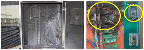
Figure 1.
Fires due to defects of crimped terminals.
2. MPC Process
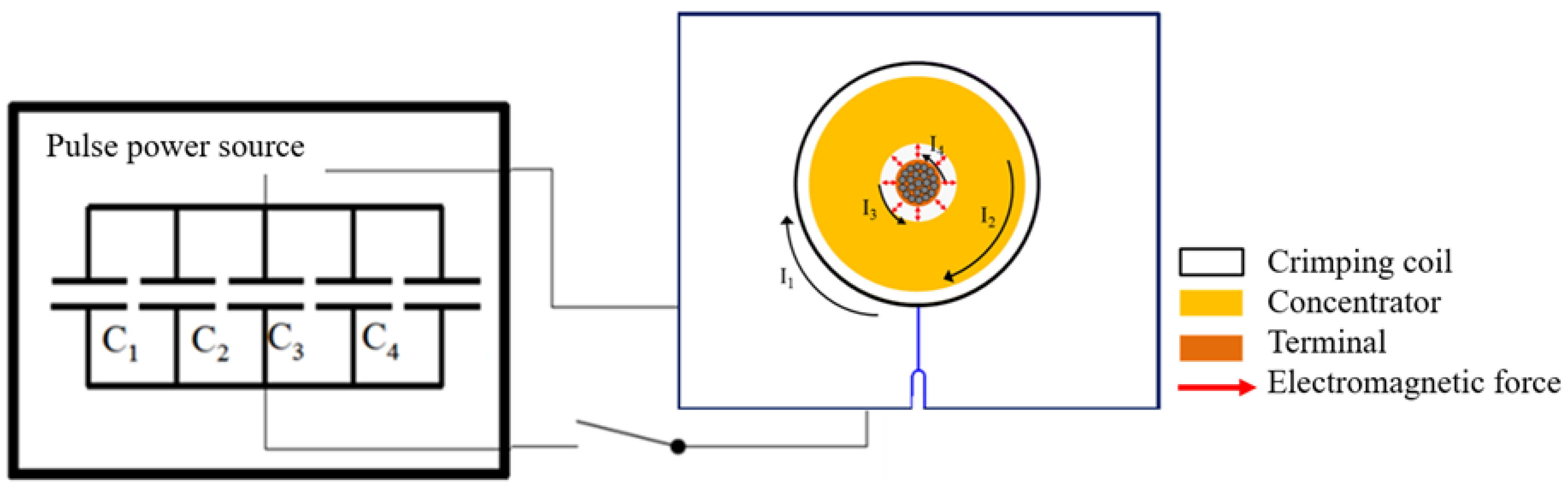
The MPC process is a high-velocity crimping process that uses magnetic force; thus, the MPC system consists of a pulse power source and a working coil with a concentrator and a loading jig, as shown in Figure 2. The pulse power source is instantaneously discharged to generate a primary current with high frequency in the working coil, as shown by I1 in Figure 2. The pulse power source is typically rated according to the energy storage capacity and stored charge energy, as follows [16]:
where E and C are the charge energy and total capacitance and V is the charge voltage. I1 will induce secondary current I2 in the concentrator and this I2 flows through the concentrator outer surface to the inner surface as I3. Finally, I4 is induced on the surface of the terminal. The high electromagnetic fields between the concentrator inner surface and the terminal surface generate a high magnetic force between them; this magnetic force leads to high velocity, which compresses the terminal toward the copper wire strands for mechanical crimping at nearly 1000 m/s [2].
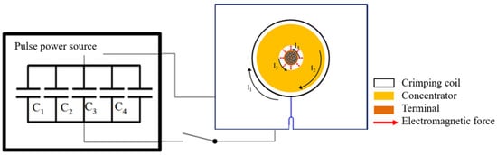
Figure 2.
Schematic view of MPC process.
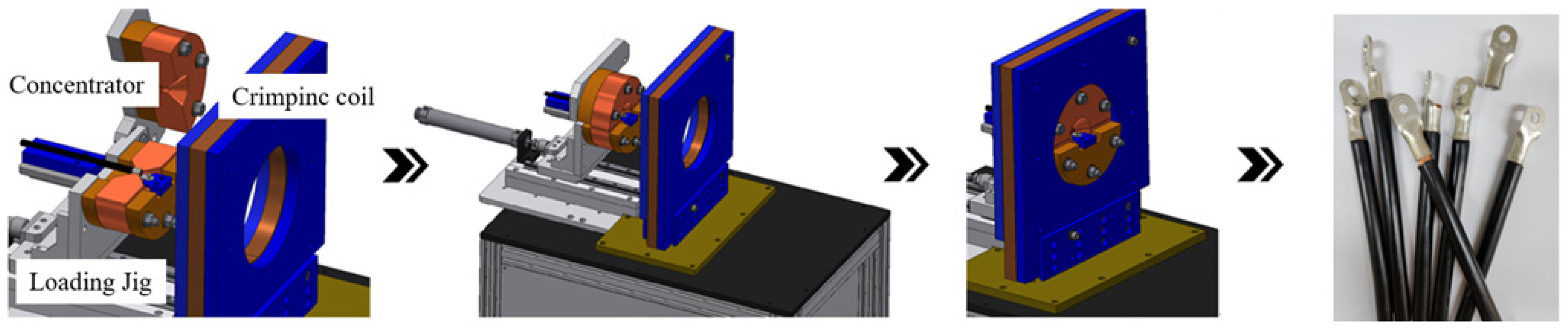
Figure 3 shows crimping of a terminal using the MPC process. Because the MPC process uses high electrical energy, it requires a remote controller and loading/unloading jig to reduce tack time and to ensure worker safety during crimping. The MPC process was initiated by inputting the terminal into a concentrator on a loading/unloading jig. Then, the concentrator traveled toward the one-turn crimping coil. It was pushed by the hydraulic compressor using an electric motor. After set-up, the electrical energy was charged to the pulse power source and then discharged by the controller to the crimping coil within a microsecond; due to this magnetic force, the terminal collided at high velocity with copper wire strands.
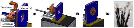
Figure 3.
Set-up of MPC process.
3. Experimental Procedure
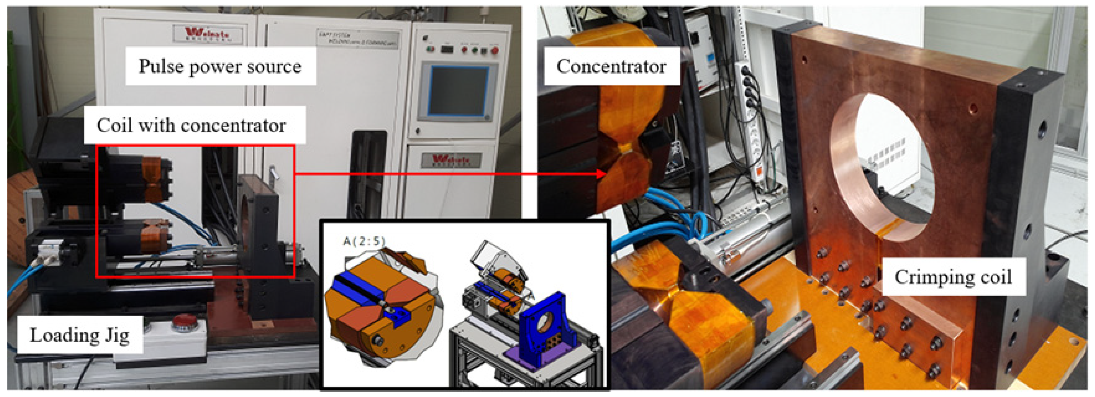
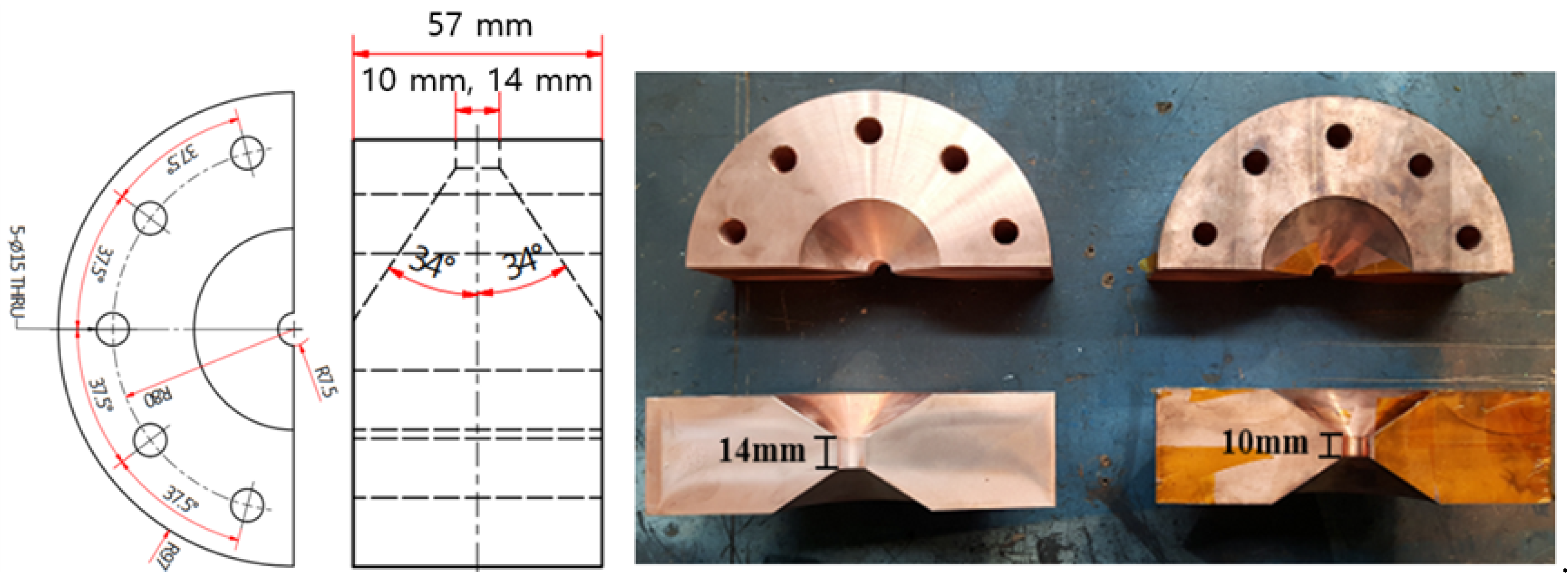
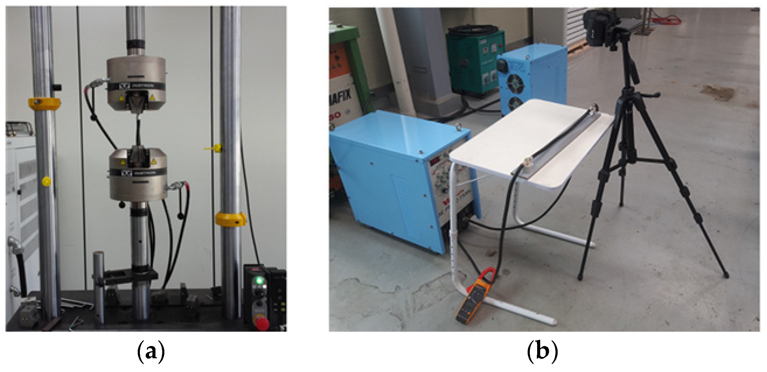
The MPC system manufactured by WELMATE Co., Ltd. of Gimpo, Korea is shown in Figure 4. The pulse power source consisted of 10 capacitors connected in parallel. The capacitors were discharged to a coil by a triggered switch unit. The total capacitance was 613 μF and the charge voltage was less than or equal to 14 kV, so the maximum charge energy was 60 kJ. In particular, two types of concentrators were designed and manufactured using beryllium copper, as shown in Figure 5.

Figure 4.
MPC system in this study.
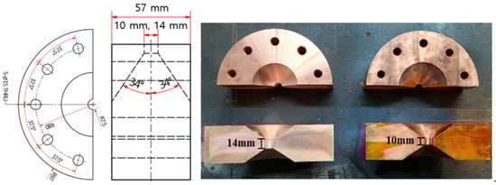
Figure 5.
Two types of designed concentrator.
We employed 1.3 mm thickness 12 mm diameter copper terminal and 35 mm2 cross-sectional area copper wire strands in this study. The terminal surface was cleaned with alcohol and dried. No special surface treatment was applied before crimping. The prepared terminal and wire were inserted into the concentrator, and the terminal was overlapped. In particular, the gap between the terminal and the concentrator was maintained at 1.0 mm to ensure high electromagnetic interaction. The Rogowski coil for measuring current during discharge time was set up at the connection part between the pulse power source and the crimping coil. Table 1 shows the crimping conditions for this study. Case A and Case B were manufactured using a compressor for the conventional crimping process; this was tried once and then a second time to achieve 10 mm and 14 mm crimped parts, respectively. As for the MPC conditions, the charge energy was varied from 20 kJ to 26 kJ. To analyze the effect of crimping length, Case D and Case E were crimped using the two types of designed concentrators with identical charge energy. Case E, Case F, and Case G were crimped using the designed concentrator with 14 mm depth under different energy levels. After crimping, the crimping parts were evaluated according to the compression ratio, crimping pullout strength, and temperature rise, as shown in Figure 6. Comparison of cross sections of crimped terminals was carried out using an optical microscope to measure voids and to calculate the compression ratio. During the crimping process, the compression ratio α was defined as the difference in wire areas before and after crimping [7].
where is the terminal diameter and is the diameter of the crimped terminal. The pullout strength was tested using the standard procedure for a wire pullout test. The MPC crimped terminal was prepared with a length of 180 mm (the terminal and wire strand length were 14 mm and 165 mm, respectively), and 15 mm of insulation was peeled off to prevent gripper slip. The transverse speed was maintained at 50 mm/min [17]. All experiments were conducted ten times to ensure reliability of results. The crimped contact resistance and temperature were measured using an LCR meter and an infrared camera.

Table 1.
Crimping conditions.
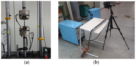
Figure 6.
Set-up of crimped part quality tests. (a) Tensile test, (b) temperature test.
4. Numerical Procedure
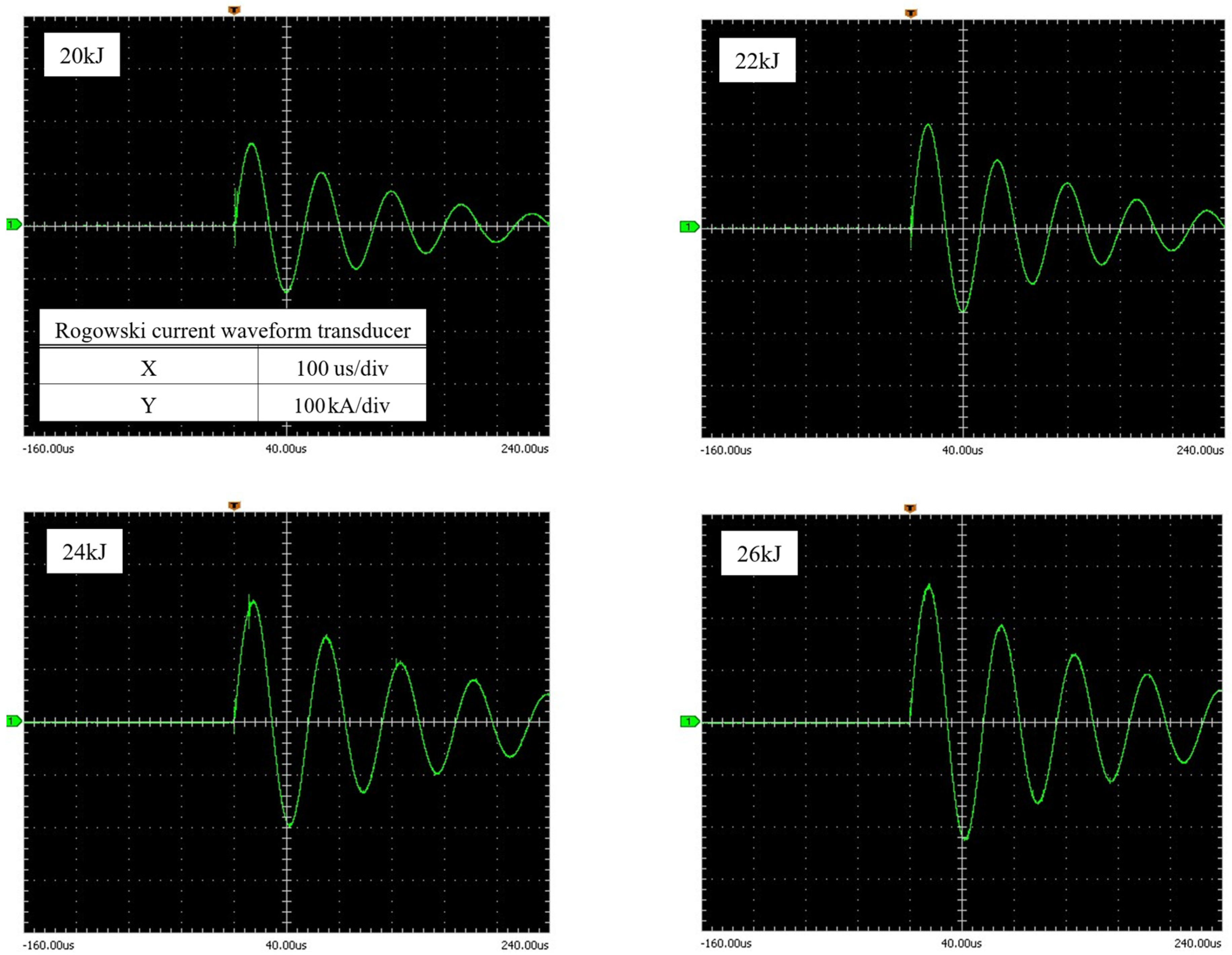
Electromagnetic–mechanical simulation is indispensable when analyzing the MPC process because it makes it possible to predict the shapes of crimped terminals by accurately identifying the magnetic force and how its distribution acts on the terminal within tens of microseconds; these values were difficult to determine in our experiment. To develop the electromagnetic-mechanical FE-model, the commercially available finite element software ANSYS/LS-DYNA (https://www.ansys.com/) was used [18]. First, an electromagnetic FE-model was established to calculate the electromagnetic force; then, a mechanical model was established to calculate the high-velocity deformation of the terminal. The crimping coil as a rigid body and the terminal as a deformable material were modeled with R3D4 and C3D8R for the FE-model. The general explicit contact algorithm was used for the terminal and wire bundle; thus, the software automatically defined the contact in the model. The Maxwell equations were solved using FEM for solid conductors and the boundary element method (BEM) for the surrounding air. The crimping coil movement was constrained in all directions, including translation and rotation. Figure 7 shows waveforms measured during crimping under various conditions. When discharge from the pulse power source had values of 20 kJ, 22 kJ, 24 kJ and 26 kJ, values of peak current of 160 kA, 200 kA, 230 kA and 268 kA were measured. For the simulation, these waveforms were input to the crimping coil as a sine wave function. However, during the MPC process, the peak current is responsible for considerable deformation, and thus up to 15 was input for the FE-model.
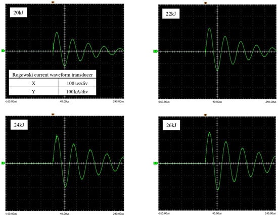
Figure 7.
Input current waveforms.
Figure 8 shows the FE-model developed to analyze the distribution of magnetic force. This FE-model consisted of concentrators, which had lengths of 10 mm and 14 mm as shown in Figure 9, and terminal and wire strands, which were simplified into a bundle. The MPC process used high-strain-rate deformation processes, so it was necessary to input the Johnson–Cook material constant parameter values as material properties [1,11,19]. Therefore, the Johnson–Cook constitutive model was used to model the behavior of the deforming terminals. The J-C equation, a combination of plastic strain and plastic strain rate, is shown in Equation (3):
where is the equivalent plastic stress (MPa), ε is the equivalent plastic strain, is the equivalent plastic strain rate (), is the reference equivalent plastic strain rate (), is the temperature (°C), is the melting temperature, and is the room temperature (°C). The J-C material properties and mechanical properties for copper material are shown in Table 2 [20]. During the MPC process, the peak current causes considerable deformation; thus, currents of 200 kA and 15 were inputted into the FE-model.
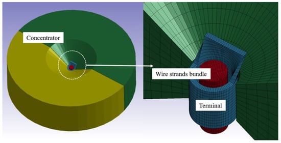
Figure 8.
FE-model for MPC process.

Figure 9.
MPC crimped terminals with different crimping lengths, analyzed using the FE-model.
Table 2.
Values of Johnson–Cook material constant parameter [11,20].
The numerical analysis was divided into two different sections. Electromagnetic analysis was used to calculate the distribution of magnetic force, which was then applied to the mechanical analysis. Figure 9 shows the results for terminals crimped by MPC with two types of concentrators. The results for the crimped terminals show good agreement with the experimental results. Therefore, the developed FE-model was employed to analyze the distribution of magnetic force during the MPC process with various values of crimping length and charge energy.
5. Results and Discussion
5.1. Compression Ratio
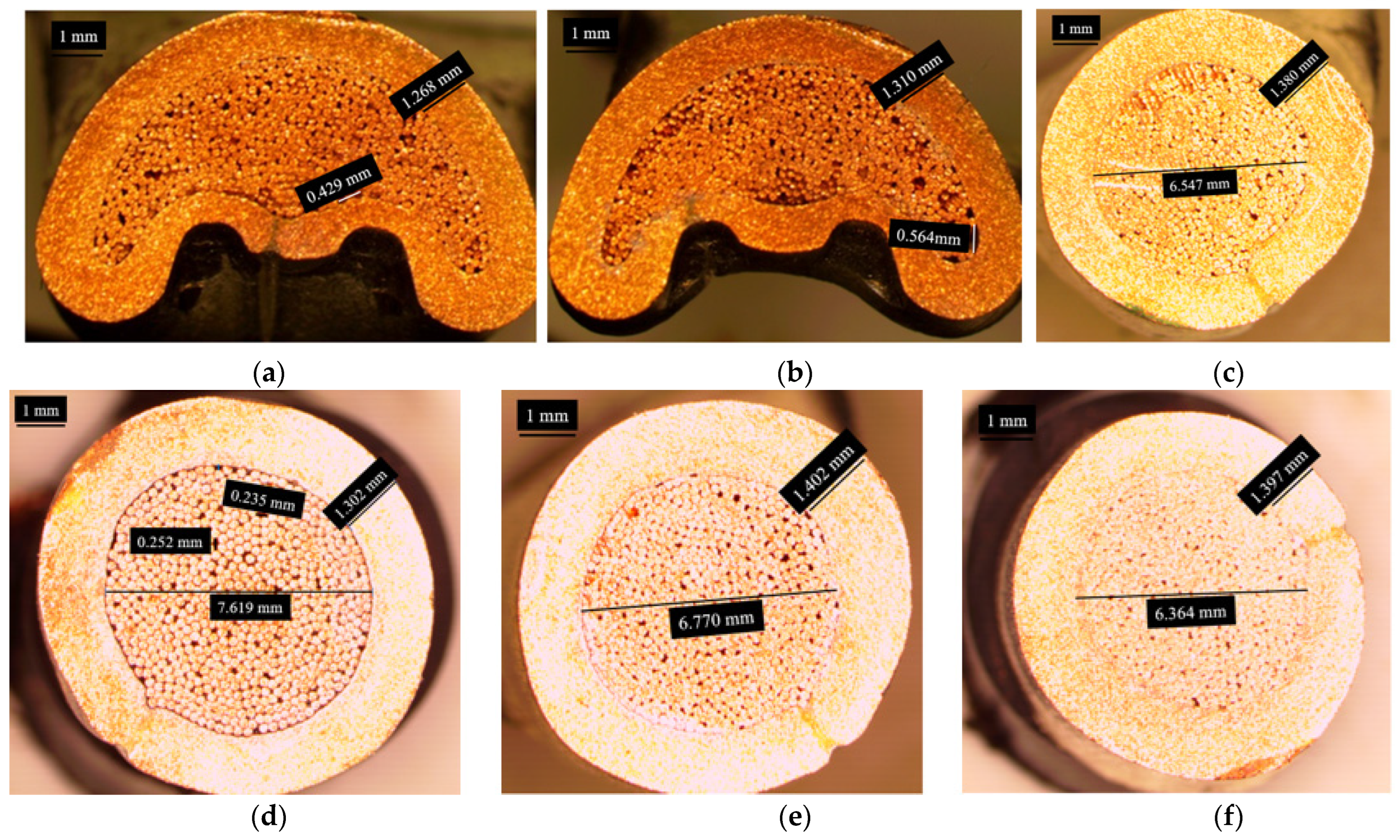
To characterize the E-SPR joints according to the rivet type, experiments were conducted by applying compressor crimping, because the conventional process results in a letter “B”-shaped crimping part. In contrast, a radial crimping part can be achieved using the MPC process. Images of cross sections are shown in Figure 10. The density of wire of the terminal formed by MPC is higher than that formed by the compressor; thus, many voids between wires and between wires and terminals can be observed in Cases A and B. One void was over 0.56 mm in size in Case B, as shown Figure 10b. It was found that, compared to those crimped by a compressor, terminals crimped by MPC show more uniform radial compression deformation and a minimum number of voids between wire strands and terminals. Figure 10c,f show cross-sections of parts formed by the MPC process. When 20 kJ charge energy was applied to the process, crimping parts were separated into wires and terminals during cutting. This shows that 20 kJ is not a sufficient energy level for crimping.
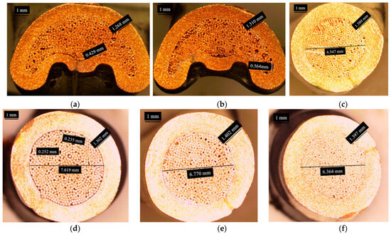
Figure 10.
Cross-sections of parts crimped under various conditions. (a) Case A, (b) Case B, (c) Case D, (d) Case E, (e) Case F, (f) Case G.
To analyze the effects of crimping length and charge energy in the MPC process, compression ratios were measured under various conditions, as shown in Figure 11. The maximum compression ratios for the crimping lengths of 10 mm and 14 mm were 30.3% and 18.9% under 22 kJ, respectively. With the increases in crimping length, the wire density in terminals decreased, and many voids between wires and between terminals and wires were observed. This means that increasing the crimping length led to a decrease in the compression ratio. The minimum compression ratio under 14 mm crimping length was 18.9%, for Case E at 22 kJ; the maximum compression ratio was 32.3% for Case G at 26 kJ. In Case E, due to the lower compaction, a gap of approximately 0.2 mm was measured between the terminal and the wire strands, as shown in Figure 10d. Very few internal gaps were observed in Case G, as shown in Figure 10f. By increasing the charge energy at the same crimping length, compression ratio was increased. Additionally, reductions in individual wires were observed in Case D, Case F, and Case G. The maximum diameter of an individual wire was 0.22 mm before crimping and 0.20 mm after crimping. The magnetic force increased with increases in charge energy. To analyze the magnetic force of the MPC process, the verified electromagnetic FE-model was employed.
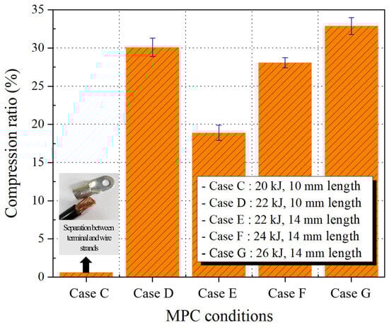
Figure 11.
Compression ratio of MPC crimped terminal.
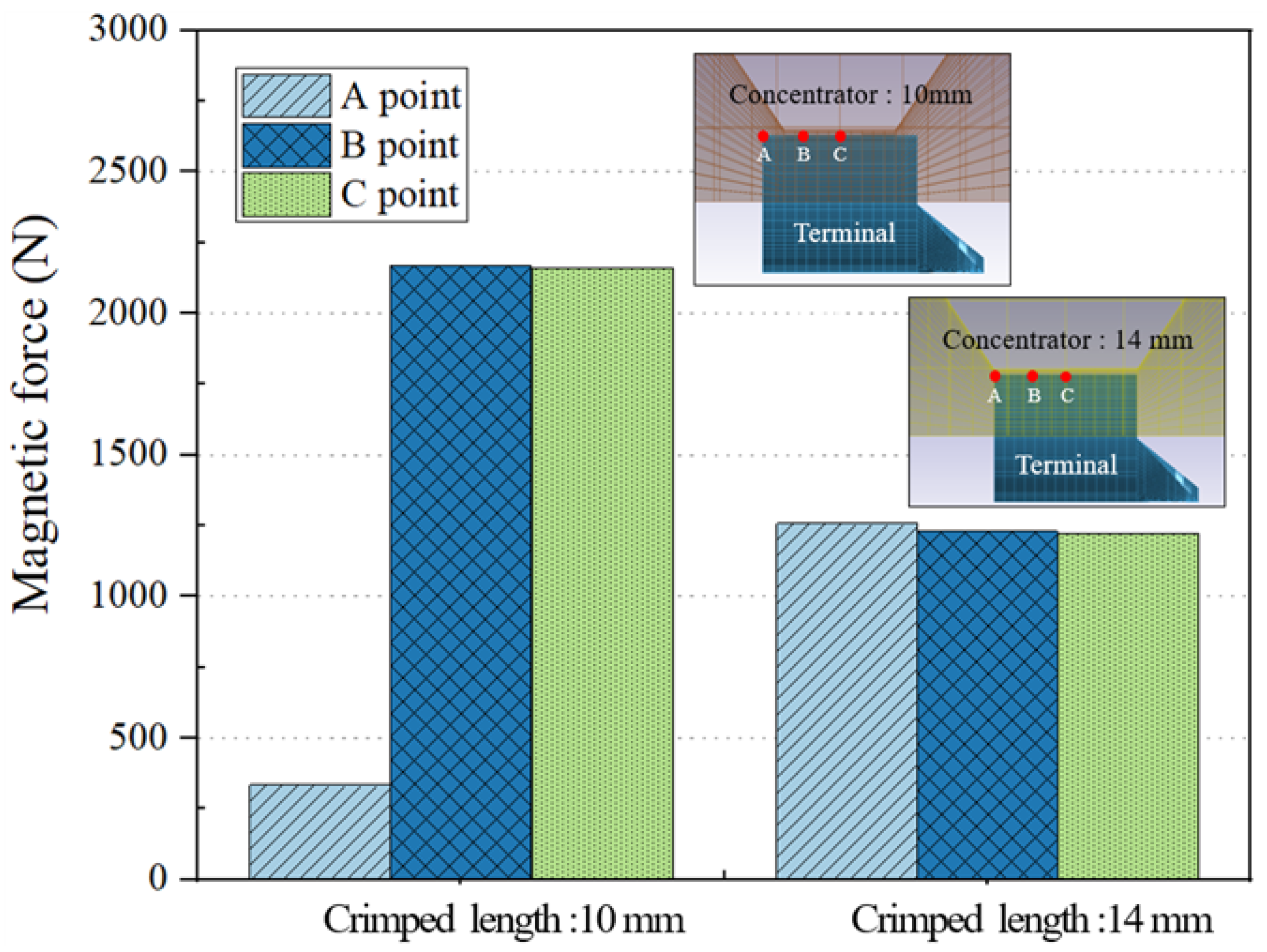
Figure 12 shows the magnetic forces produced by the two types of concentrator during crimping. The maximum magnetic forces were calculated at 2150 N and 1250 N for Case D and Case E, respectively. The higher magnetic force was achieved using the 10 mm concentrator; the overall difference was about 900 N. However, at point C in Case D, the magnetic force decreased sharply because the gap between the concentrator and the terminal was over 2 mm and electromagnetic integration was too weak. On the contrary, unit-form magnetic force was achieved in Case E. Figure 13 shows the distribution of the magnetic force with variation in the charge energy. With increasing charging energy and identical crimping length, the magnetic force increased by about 700 N.
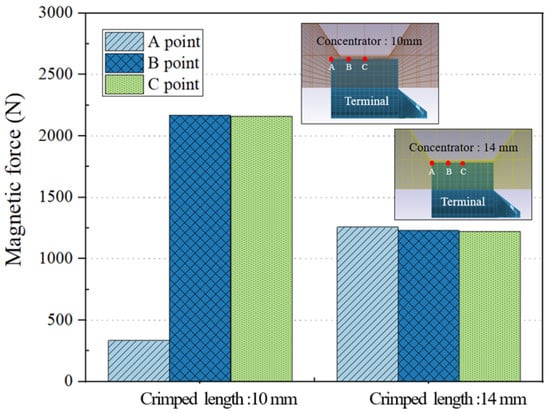
Figure 12.
Magnetic force values of two types concentrator (charge energy: 22 kJ).
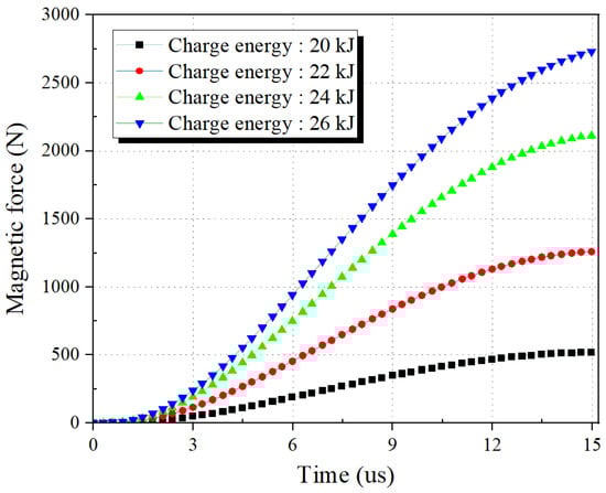
Figure 13.
Magnetic force values with various energy charges (concentrator length 14 mm).
These results confirm that decreasing the crimping length and increasing the charge energy are effective ways of improving the crimped terminal quality.
5.2. Pullout Strength of Crimped Part
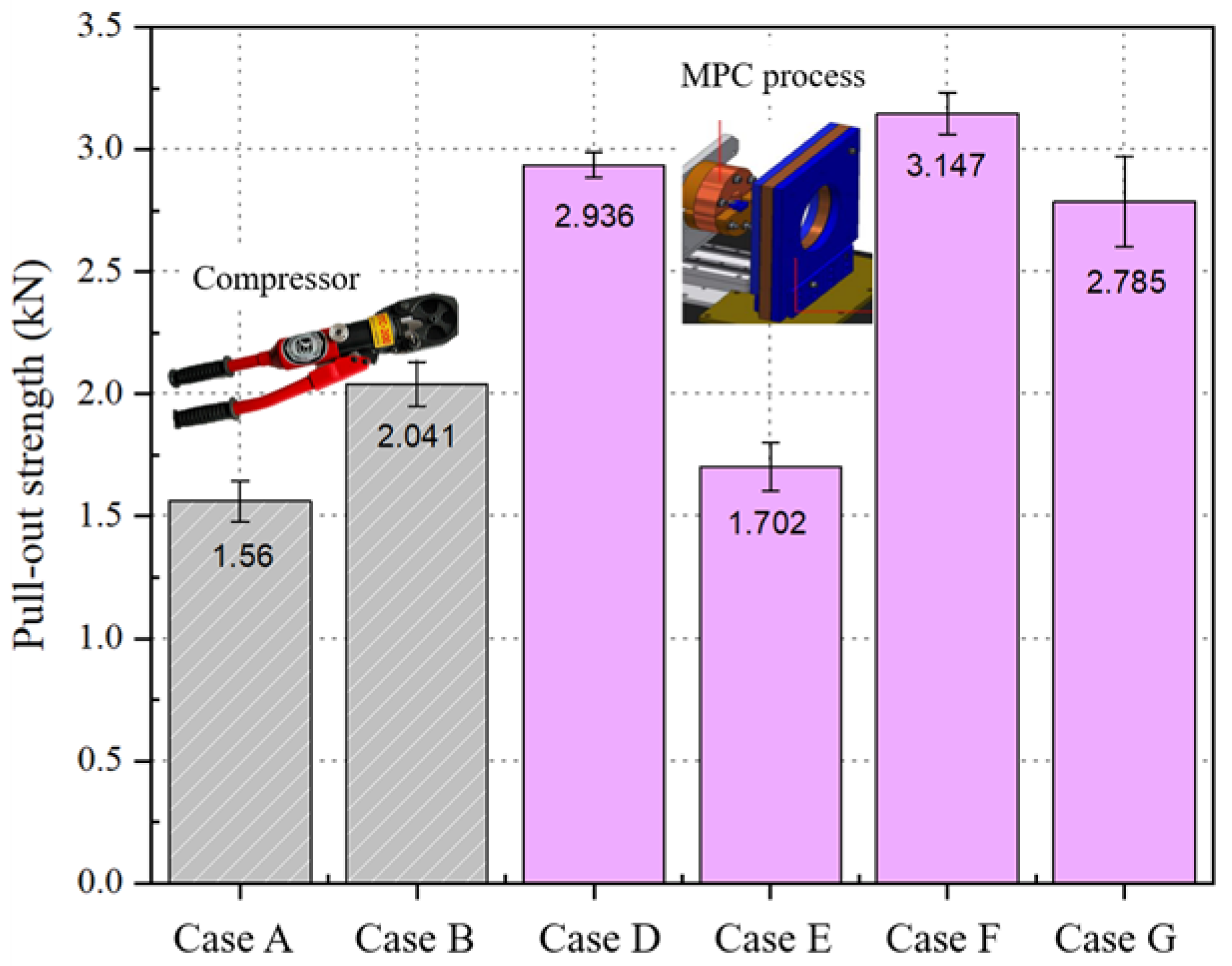
During the operation of a system connected with a crimped terminal, occurrence of separate terminals and wires can cause many kinds of damage, such as fire and system breakdown. Therefore, pullout strength is a very important factor required to maintain terminal function during energy transmission. Figure 14 shows the strength of the pullout tests for the various crimping conditions. The pullout strengths induced by the compressor for Case A and Case B were measured at 1.560 kN and 2.041 kN under different crimping lengths. Because the crimping length increased from 10 mm to 14 mm in Case B, the pullout strength increased slightly. During the MPC process, the pullout strengths of Case D and Case E were measured at 2.936 kN and 1.702 kN, respectively. When the crimping length increased from 10 mm to 14 mm with 22 kJ charge energy, the pullout strength decreased by about half. Because the magnetic force for crimping decreased according to the increasing crimping length, as seen in Section 5.1, the pullout strength decreased sharply in Case E. To analyze the effect of charge energy, the pullout strength values of Cases E, F, and G were compared. The pullout strengths of Case E and Case F were 1.702 kN and 3.147 kN; it was found that increasing the charge energy led to increased pullout strength due to the increased magnetic force, as shown in Figure 14. The pullout strength depends on the compression ratio of the plasticized crimp between the terminal and the wire strands [21]. The compression ratio increases with deformation, which increases with charge energy. Unexpectedly, the pullout strength decreased in Case F, which was manufactured to have the highest charge energy. Because a portion of copper wire strands adjacent to the edge of the terminal were squashed and compressed during crimping by the high magnetic force, this sample broke easily during the pullout strength test. From these results, it can be confirmed that, although compared to the compressor process the MPC process is effective in terms of pullout strength, too-high charge energy can lead to decreased pullout strength. Therefore, proper charge energy selection is important to achieve high-quality MPC crimped parts.

Figure 14.
Pullout strength of crimped terminals under various conditions.
5.3. Contact Resistance and Temperature
The most important role of crimped terminals is current flow from power supply to equipment; thus, contact resistance is important to prevent energy loss. The lower the contact resistance, the less heat is generated at the crimped terminal. A properly crimped terminal should have minimum contact resistance to ensure maximum current flow through it [11]. For this reason, the contact resistance and the temperature of the terminal surface were measured; the values are presented in Table 3. The contact resistance of terminals crimped using compressors was approximately 33 mΩ, while the contact resistance of terminals crimped according to MPC varied with crimping length and charge energy. The contact resistances of Case D and Case E were measured and found to be 26.1 mΩ and 30.8 mΩ, respectively. With the increase in crimping length, the resistance values increased under identical charge energy. The contact resistance of Cases E, F, and G were compared to investigate the effect of charge energy. The contact resistances of Case E and Case F were measured at 30.8 mΩ and 24.8 mΩ. These results show that increasing the charge energy led to decreased contact resistance of MPC crimped parts.
Table 3.
Contact resistance of crimped terminals.
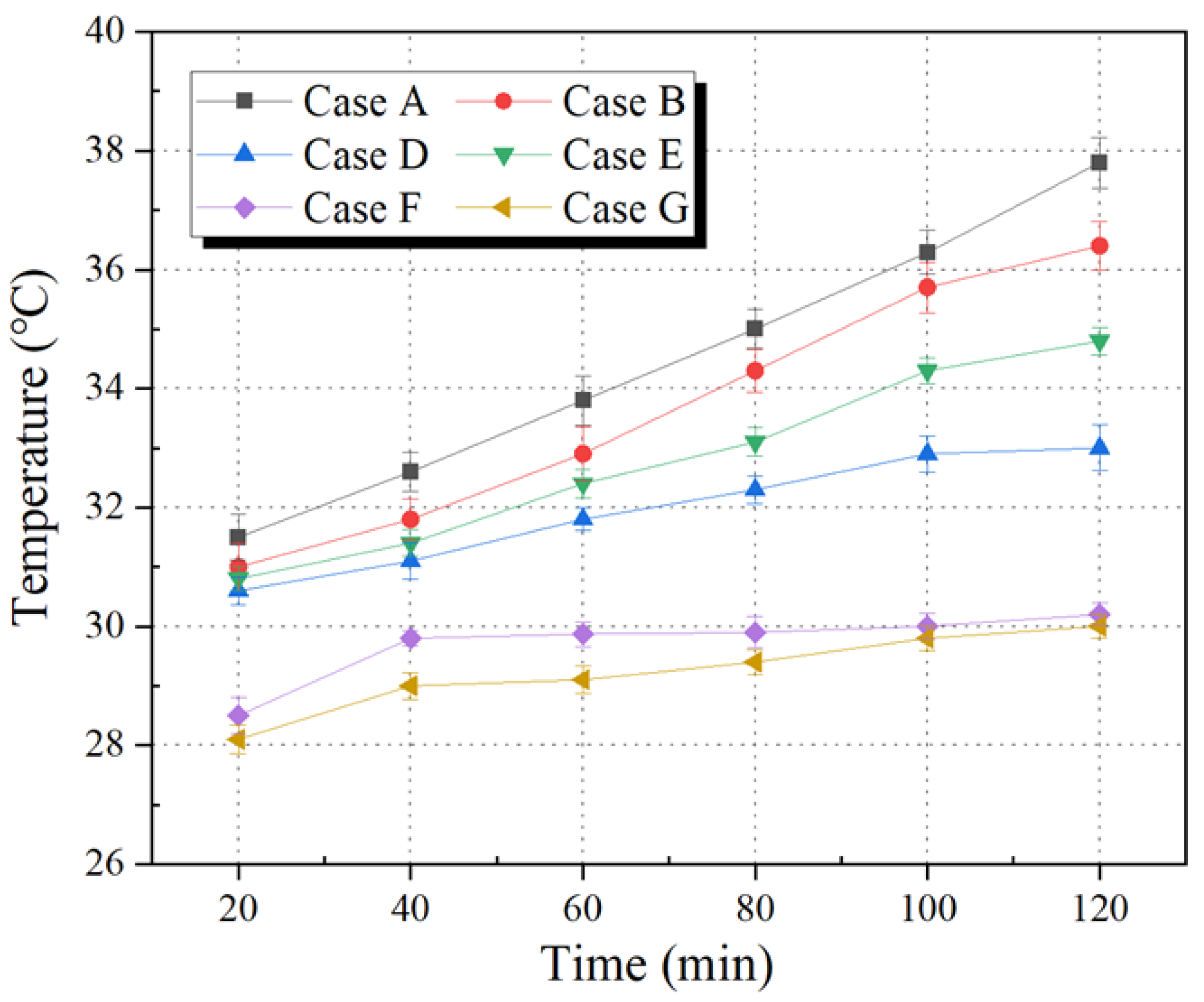
Figure 15 shows measured temperatures of crimped terminals under various conditions over a period of 120 min. After 40 min, the temperature of the terminal crimped using a compressor was measured and found to be approximately 32.5 °C. The MPC terminal had a temperature of 31.1 °C. As time passed, the temperature difference increased and, after 120 min, the maximum temperature of the terminals crimped using the compressor and MPC were 37.8 °C for Case A and 34.3 °C for Case E.
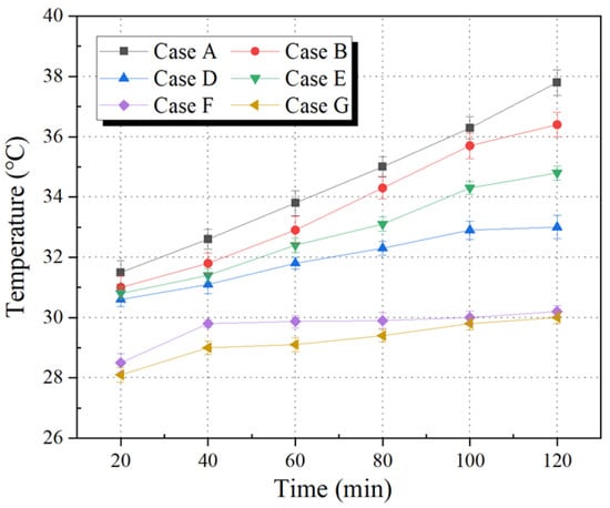
Figure 15.
Temperature of terminals crimped under various conditions.
Generally, increasing contact resistance causes a temperature rise. In particular, the temperatures of Cases D and F were compared to select the proper MPC condition; it was found that the temperature rise of Case D was higher than that for Case F, as shown in Figure 16. From these results, it can be seen that increasing the charge energy is a better method of achieving high-quality crimping parts than decreasing the crimping length.
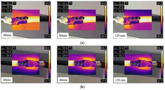
Figure 16.
Effects of charge energy and crimping length on temperature rise of crimped terminal. (a) Charge energy 22 kJ, crimping length 10 mm; (b) charge energy 26 kJ, crimping length 14 mm.
6. Conclusions
In the present study, the superiority of the MPC process compared to the conventional crimping process was verified and the effects of main process parameters, which include crimping length and charge energy, on MPC crimped parts were analyzed via experimental and numerical work. The observations from this study can be summarized as follows:
- (1)
- The effect of crimped length on crimped terminal quality was analyzed for the first time. When the crimped length was 10 mm in the MPC process, the maximum values of the compression ratio and pullout strength of MPC were 32.3% and 3.147 kN, respectively.
- (2)
- The electromagnetic–mechanical FE-model was developed to analyze the MPC process; the simulation results were in good agreement with the experimental deformation results. To employ the developed FE-model, the effect of concentrator length and the effect of charge energy on the crimped terminal were quantitatively analyzed. The achieved distribution of electromagnetic force on crimped terminal can be applied as fundamental data to terminals of similar shape.
- (3)
- The effect of crimping length on MPC crimped parts was investigated using two types of concentrator, with crimping lengths of 10 mm and 14 mm. With increases in the concentrator length, the quality of crimped parts decreased sharply. From the simulation results, it was confirmed that the electromagnetic force decreased by 20% at a concentrator length of 14 mm.
- (4)
- The effect of charge energy on MPC crimped parts was measured according to variation in charge energy. With the increase in charge energy from 20 kJ to 24 kJ, the compression ratio and pullout strength increased. The simulation results confirmed that the electromagnetic force increased by 30% as the charge energy increased.
- (5)
- High-quality MPC crimped parts can be obtained by reducing the crimping length and increasing the charge energy. When applying the MPC process on site, the most significant values were the contact resistance and temperature. The results show that, to achieve high-quality crimped terminals, increasing the charge energy is a more effective method than reducing the crimping length.
- (6)
- Although 26 kJ electrical energy was employed for terminal crimping, the lowest pull-out strength was measured because a portion of wire strands adjacent to the edge of the terminal were squashed. This result shows that selection of proper charging energy is the most important factor for achieving high-quality crimped terminals. These results can contribute to the design of MPC processes for many kinds of crimping components in various industries.
Author Contributions
Conceptualization, J.S.; Methodology, J.S.; Software, M.K.; Formal analysis, J.S.; Investigation, M.K.; Resources, M.K.; Writing—original draft, M.K.; Writing—review and editing, J.S.; Supervision, J.S. All authors have read and agreed to the published version of the manuscript.
Funding
This research was financially supported by A project to support the development of Ppuri and agricultural machinery technology in Jeollabuk-do using KITECH infrastructure (No. IZ230015).
Data Availability Statement
All data supporting the reported results are included in the manuscript.
Conflicts of Interest
The authors declare no conflict of interest.
References
- Rhodes, E. Electrical contacts. Nature 1946, 158, 647. [Google Scholar] [CrossRef]
- Shim, J.Y.; Kang, B.Y. Development of Cable Lug Joint Using Electromagnetic Force. J. Korean Soc. Manuf. Technol. Eng. 2013, 22, 156–161. [Google Scholar] [CrossRef]
- Jongwuttanaruk, K.; Thavornwat, C. Optimization of Mechanical Crimping in the Terminal Crimping Process Using a Response Surface Methodology. Adv. Mater. Sci. Eng. 2022, 2022, 6508289. [Google Scholar] [CrossRef]
- Magnetic Pulse Crimping and High Power Solutions; SAE Technical Paper; SAE International: Warrendale, PA, USA, 2015; pp. 4–14. [CrossRef]
- Zhmurkin, D.V.; Corman, N.E.; Copper, C.D.; Hilty, R.D. 3-Dimensional numerical simulation of open-barrel crimping process. In Proceedings of the 54th IEEE Holm Conference on Electrical Contacts, Orlando, FL, USA, 27–29 October 2008; pp. 178–184. [Google Scholar] [CrossRef]
- Weddeling, C.; Demir, O.K.; Haupt, P.; Tekkaya, A.E. Analytical methodology for the process design of electromagnetic crimping. J. Mater. Process. Technol. 2015, 222, 163–180. [Google Scholar] [CrossRef]
- Yin, Z.; Park, J.G.; Choi, H.S.; Kim, Y.S. Quality Improvement for Crimping Process of Electrical Connector Using FEM Analysis. Trans. Mater. Process. 2009, 18, 229–235. [Google Scholar] [CrossRef]
- Li, P.; Liu, G.; Wang, P.; Huang, G.; Yu, Z.; Xiu, H.; Tian, C. Numerical and experimental study on the relationship between pull out force and indentation depth of aviation wire crimp terminal. Sci. Rep. 2022, 12, 21939. [Google Scholar] [CrossRef] [PubMed]
- Heggemann, T.; Psyk, V.; Oesterwinter, A.; Linnemann, M.; Kräusel, V.; Homberg, W. Comparative Analysis of Electrohydraulic and Electromagnetic Sheet Metal Forming against the Background of the Application as an Incremental Processing Technology. Metals 2022, 12, 660. [Google Scholar] [CrossRef]
- Ali, N.; Sharma, S.K.; Chebolu, R.; Nallu, R.; Sharma, A. Experimental investigations on magnetic pulse crimping of copper lug. Eng. Res. Express 2023, 5, 015055. [Google Scholar] [CrossRef]
- Rajak, A.K.; Kore, S.D. Numerical simulation and experimental study on electromagnetic crimping of aluminium terminal to copper wire strands. Electr. Power Syst. Res. 2018, 163, 744–753. [Google Scholar] [CrossRef]
- Shen, T.; Li, C.; Zhou, Y.; Wu, H.; Wang, X.; Xu, Q. The effect of assembly of coil and field shaper on electromagnetic pulse crimping. Energy Rep. 2022, 8, 1243–1248. [Google Scholar] [CrossRef]
- Saxena, R.; Sharma, S.K. Investigation of pulse power technology for crimping of electrical cables. In Proceedings of the 2021 IEEE 2nd International Conference on Applied Electromagnetics, Signal Processing, & Communication (AESPC), Bhubaneswar, India, 26–28 November 2021. [Google Scholar] [CrossRef]
- Weddeling, C.; Walter, V.; Haupt, P.; Tekkaya, A.E.; Schulze, V.; Weidenmann, K.A. Joining zone design for electromagnetically crimped connections. J. Mater. Process. Technol. 2015, 225, 240–261. [Google Scholar] [CrossRef]
- Mentec, R.L.; Sow, C.T.; Heuzé, T.; Patrick, R.; Racineux, G. Electrohydraulic Crimping of Tubes within Rings. Metals 2023, 13, 1382. [Google Scholar] [CrossRef]
- Shim, J.Y.; Kang, B.Y.; Kim, I.S. Characteristics of Al/steel magnetic pulse tubular joint according to discharging time. J. Mech. Sci. Technol. 2017, 31, 3793–3801. [Google Scholar] [CrossRef]
- Rajak, A.K.; Kore, S.D. Experimental investigation of aluminum–copper wire crimping with electromagnetic process: Its advantages over conventional process. J. Manuf. Process. 2017, 26, 57–66. [Google Scholar] [CrossRef]
- Hallquist, J.O. LS-DYNA Theoretical Manual; Livermore Software Technology Corporation: Livermore, CA, USA, 1991. [Google Scholar]
- Sobolev, A.V.; Radchenko, M.V. Use of Johnson–Cook plasticity model for numerical simulations of the SNF shipping cask drop tests. Nucl. Energy Technol. 2016, 2, 272–276. [Google Scholar] [CrossRef]
- Rajak, A.K.; Kore, S.D. Electromagnetic Hemming of Aluminum Sheets Using FEM; Atlantis Press: Amsterdam, The Netherlands, 2017; pp. 77–82. [Google Scholar] [CrossRef]
- Rajak, A.K.; Kore, S.D. Comparison of different types of coil in Electromagnetic terminal-wire crimping process: Numerical and experimental analysis. J. Manuf. Process. 2018, 34, 329–333. [Google Scholar] [CrossRef]


Disclaimer/Publisher’s Note: The statements, opinions and data contained in all publications are solely those of the individual author(s) and contributor(s) and not of MDPI and/or the editor(s). MDPI and/or the editor(s) disclaim responsibility for any injury to people or property resulting from any ideas, methods, instructions or products referred to in the content. |
© 2023 by the authors. Licensee MDPI, Basel, Switzerland. This article is an open access article distributed under the terms and conditions of the Creative Commons Attribution (CC BY) license (https://creativecommons.org/licenses/by/4.0/).