Article

Influence of Heat Treatment on Microstructure and Mechanical Properties of Direct-Quenched Fe-0.06C-0.2Si-2.0Mn Steel

Department of Materials Science and Engineering, Seoul National University of Science and Technology, Seoul 01811, Republic of Korea
*
Author to whom correspondence should be addressed.
Metals 2023, 13(12), 1912; https://doi.org/10.3390/met13121912
Submission received: 6 October 2023 / Revised: 5 November 2023 / Accepted: 18 November 2023 / Published: 21 November 2023

Abstract

:
In this study, the effect of subsequent heat treatment applied to high-strength low-alloy steel (HSLA) on the structure–property relationships was investigated. Tempering and intercritical annealing processes are introduced to elucidate the influence of subsequent heat treatment on mechanical properties of direct-quenched Fe-0.06C-0.2Si-2.0Mn steel from a microstructural perspective. The tempering process results in a typical tempered martensite with uniformly dispersed cementite, whereas the intercritical annealing process forms a dual-phase microstructure composed of soft ferrite and hard martensite for the direct-quenched steel. In the intercritical annealed steel, a number of mobile dislocations at the interphase (martensite/ferrite) boundary significantly decrease the yield strength, and the large difference in strength between ferrite and martensite enhances work hardening. Charpy V-notch impact test results indicate that the tempering and intercritical annealing processes improved the absorbed energy by more than 100 J compared to the direct-quenched steel at room temperature, and at −50 °C, the intercritically annealed steel exhibited the highest absorbed energy of approximately 140 J. Additionally, the high fraction of high-angle grain boundaries and fine grains of the intercritically annealed steel increase the resistance to cleavage crack propagation, thereby reducing the ductile-to-brittle transition temperature.

1. Introduction

High-strength low-alloy (HSLA) steels are highly demanded as structural materials for offshore, shipbuilding, bridges, and pressure vessels because of their excellent combination of strength, weldability, and low-temperature toughness [1,2,3,4,5]. In recent years, the requirement for excellent deformability, such as low yield-to-tensile strength ratio, high uniform elongation, and work hardening exponent, has arisen to increase resistance to progressive or abrupt deformation in HSLA steels [6,7,8,9,10]. Alloy design and heat treatment are important for achieving excellent mechanical properties. For instance, in the case of alloy design, HSLA steels should have low carbon content to achieve superior weldability and low-temperature toughness. Alloying elements such as chromium (Cr), molybdenum (Mo), and nickel (Ni) can improve hardenability and provide a uniform microstructure in HSLA steels [11,12,13]. Additionally, high strength can be achieved via the formation of fine precipitates using microalloying elements such as niobium (Nb), vanadium (V), and titanium (Ti) [14,15].
On the other hand, to meet the mechanical properties required for HSLA steels, researchers have extensively investigated various heat treatment processes over the past decades [16,17,18,19,20]. Quenching and tempering, controlled rolling, and thermomechanical control process are the conventional methods used to fabricate HSLA steels. These heat treatment processes are advantageous for achieving certain mechanical properties; however, they are restricted in terms of simultaneously satisfying strength, toughness, and deformability requirements. The quenching and tempering process is known as one of the most useful heat treatments for fabricating HSLA steels. The formation of martensite via quenching is a typical method for increasing strength, and dislocation recovery during the subsequent tempering can enhance the toughness of quenched steels. Although withing the quenching and tempering process it is easy to control the processing conditions, and it can ensure high strength and toughness, it exhibits poor low-temperature toughness and a high yield-to-tensile strength ratio. These disadvantages of the quenching and tempering process severely limit the industrial application of HSLA steels.
Therefore, achieving good deformability and low-temperature toughness while maintaining high strength has become an increasingly important issue for HSLA steels [21,22]. Among HSLA steels, dual-phase steels, which are typically fabricated via intercritical annealing, can offer a good combination of strength, deformability, and low-temperature toughness due to the specific microstructure with ferrite and martensite [23,24,25]. In addition to these characteristics, they exhibit a high rate of work hardening, a low yield-to-tensile strength ratio, and continuous yielding behavior. The mechanical properties of dual-phase steels vary substantially depending on the morphology, volume fraction, and distribution of hard martensite [26,27,28].
Most researchers alter process parameters within the same heat treatment method and take into account the correlation between microstructure and mechanical properties to determine the effect of heat treatment on HSLA steels. However, studies that simultaneously compare various heat treatment methods to enhance the mechanical properties of HSLA steel and examine them in terms of microstructure have been limited. A thorough investigation from a microstructural perspective is necessary to comprehend the effect of the various heat treatment methods currently applied to HSLA steel on mechanical properties.
The objective of this study is to investigate the influence of tempering and intercritical annealing processes on the microstructure and mechanical properties of direct-quenched Fe-0.06C-0.2Si-2.0Mn steel. Based on the structure–property relationship, we focus on the microstructural evolution and changes in the strength, deformability, and low-temperature toughness of the abovementioned steel after it is subjected to heat treatment. The initial microstructure having a fully lath martensite before the tempering and intercritical annealing processes is also examined to further comprehend the influence of the heat treatment.

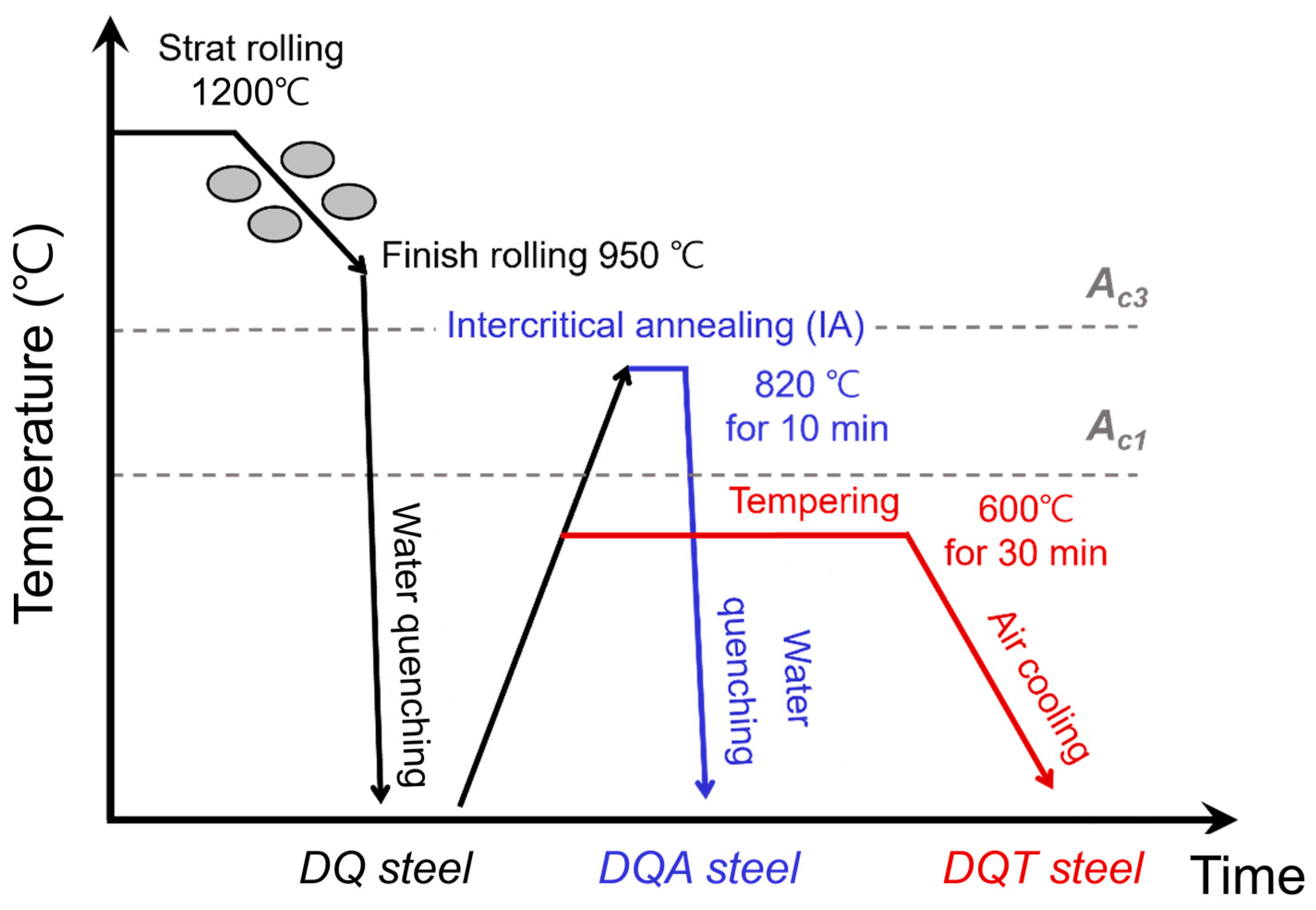
2. Materials and Methods

The chemical composition of the low-carbon HSLA steel investigated in this study was Fe-0.061C-0.19Si-2.01Mn-0.03Al-0.20Cu-0.39Ni-0.39Cr-0.25Mo-0.04V-0.01Ti (wt. %). The ingot of the investigated steel was forged and cut into blocks of ~98 mm thickness, and then the blocks were hot rolled to a thickness of ~12 mm. The start and finish rolling temperatures were 1200 °C and 950 °C, respectively. Finally, the hot-rolled HSLA steel with a thickness of 12 mm was directly quenched to room temperature in water.
Three types of low-carbon HSLA steels with different microstructures were fabricated via direct quenching, tempering, and intercritical annealing, as shown in Figure 1. The steels subjected to various processes are referred to as “DQ (direct-quenching)”, “DQT (direct-quenching and tempering)”, and “DQA (direct-quenching and intercritical annealing)” for clarity. The “DQ” steel was fabricated through only water quenching after hot rolling to obtain a fully martensitic microstructure. The steels subjected to direct quenching were classified into two groups: the steel tempered at 600 °C for 30 min is “DQT”, and the steel that was intercritically annealed at 820 °C for 10 min is “DQA”.
The longitudinal-transverse (L-T) plane of the steels was mechanically polished and etched using a 3% Nital solution, and then the microstructures were examined using an optical microscope and a field-emission scanning electron microscope (FE-SEM, model: JSM-6700F, JEOL, Tokyo, Japan). Electron back-scatter diffraction (EBSD, model: EDAX-TSL with Hikari XP camera, AMETEK, Berwyn, IL, USA) equipped with a field-emission scanning electron microscope (FE-SEM, model: JSM-7100F, JEOL, Japan) was used to analyze the specimens after they were polished using a suspension of 0.04 μm colloidal silica particles. The acceleration voltage, working distance, and step size for the EBSD analysis were 20 kV, 16 mm, and 0.04 μm, respectively. The EBSD data were interpreted using orientation imaging microscopy analysis software (TSL-OIM 7.0, TexSEM Laboratories, Draper, UT, USA) to characterize the microstructure.
Tensile tests were performed at a strain rate of 1.0 × 10⁻³·s−1 using a 10-ton universal testing machine (model: UT-100E, MTDI, Daejeon, Republic of Korea) in accordance with the ASTM E8 standard test method [29]. Sub-sized round-type tensile specimens, with a gauge diameter and length of 6.3 mm and 25.4 mm, respectively, were prepared in the rolling direction. The yield strength was defined as 0.2% offset in the engineering stress-strain curve, and the work hardening exponent was calculated from the true stress-strain curve based on the Hollomon equation [30].
Hardness was measured using a micro-Vickers hardness tester (FM-800, Future-tech, Kawasaki, Japan) with a load of 300 gf for 15 s. Nanoindentation was also performed using a Hysitron TriboIndenter (model: TI-950, Bruker, Billerica, MA, USA), with a Berkovich tip. Before performing the nanoindentation test, all test specimens were mechanically polished and electropolished in a mixed solution of 80% ethanol (C2H6O) and 20% perchloric acid (HClO4). After a loading–unloading period of 30 s and a constant load of 3 mN was programmed, an array of 25 (5 × 5) nanoindentations were performed on all steels at an indentation spacing interval of 5 μm.
Charpy V-notch (CVN) impact tests were performed at temperatures ranging from −150 °C to 25 °C using an impact testing machine (model: PSW750, Zwick Roell, Ulm, Germany) of 750 J capacity on the specimens with a size of 10 mm × 10 mm × 55 mm and orientations in the transverse-longitudinal (T-L) direction in accordance with the ASTM E23 standard test method [31]. The fracture surfaces of the CVN specimens fractured at −50 °C, −20 °C, and 25 °C were observed using SEM to examine the fracture mode of the HSLA steel investigated in this study.

3. Results and Discussion
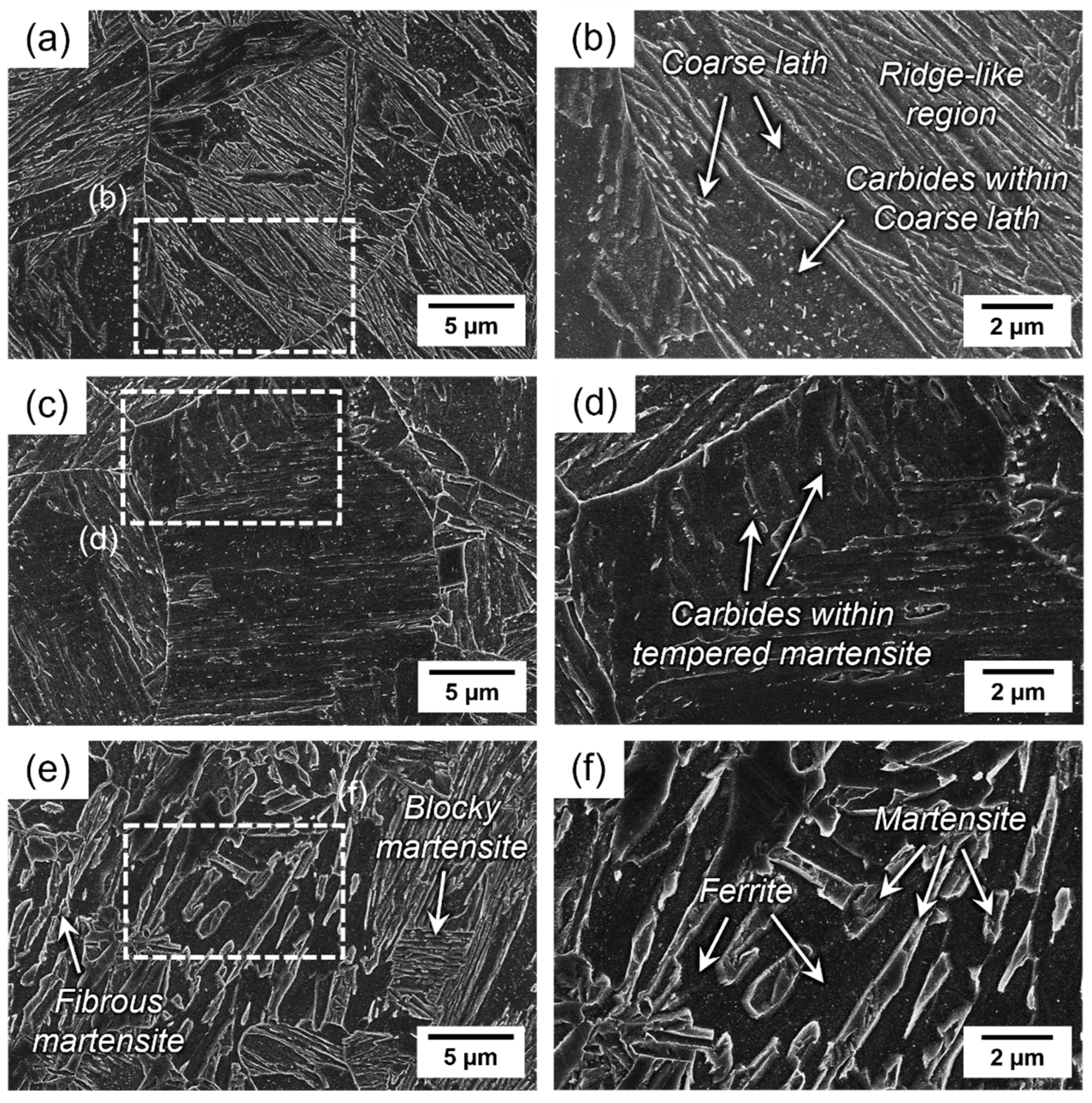
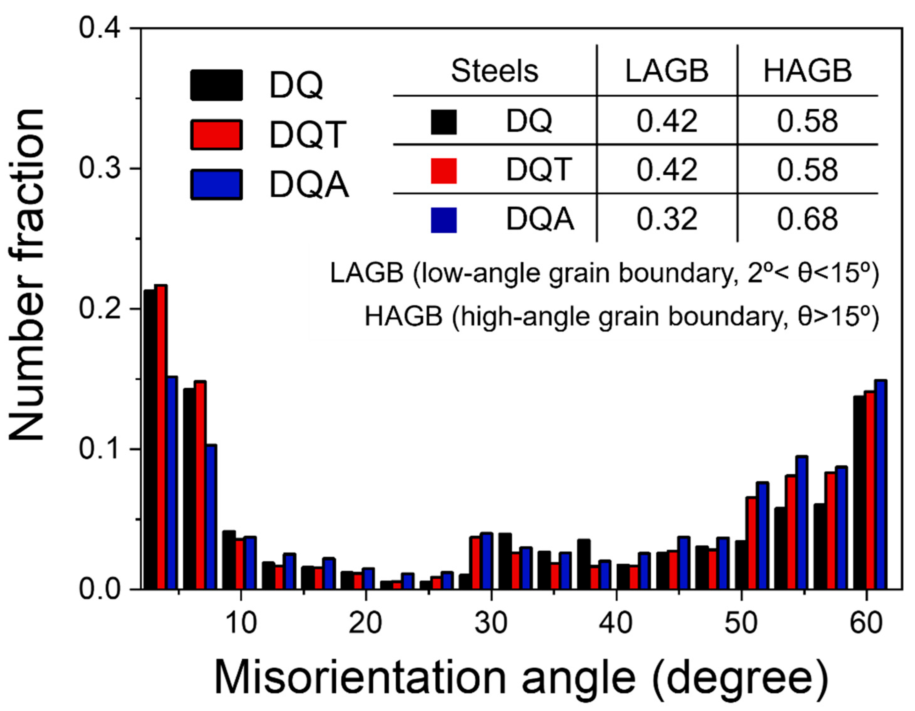
3.1. Microstructure

The SEM images of the HSLA steels investigated in this study are shown in Figure 2. The DQ steel exhibited the typical fully lath martensitic microstructure observed in conventional quenched low-carbon steels (Figure 2a). As shown in the enlarged SEM image of the DQ steel (Figure 2b), some carbides were formed within the laths of the DQ steel. Since the formation of these carbides is similar to the precipitation mechanism of tempered martensite, it is typically referred to as the auto-tempering that occurs in low-carbon martensitic steels [32,33]. Given that low-carbon steels have a relatively high martensite start temperature (MS), cementite can be formed within laths even at a cooling rate of 1000 °C/s and has sufficient time to grow because the mobility of carbon in ferrite is relatively high when close to the MS temperature [32,33].
After tempering the DQ steel, tempered martensite was observed in the DQT steel, as shown in Figure 2c. Unlike the several thin and coarse laths that appeared in the DQ steel, fine and uniformly dispersed carbides precipitated during the tempering process were observed in the DQT steel (Figure 2d). Although lath martensite was recovered by tempering, the parallel crystal alignment generated in the packets and blocks of the DQ steel remained. After tempering, the matrix microstructure comprised ferrite with an extremely low carbon content; however, it was regarded as tempered martensite because it was derived from lath martensite and had packet/block characteristics [34].
By contrast, a dual-phase microstructure composed of a soft ferrite matrix and a hard second phase (martensite) was formed in the DQA steel (Figure 2e) [23]. Austenite reverts during the intercritical annealing process and transforms into martensite or bainite after cooling, depending on the chemical composition of the HSLA steels and the cooling rate [24]. The volume fraction of martensite in the DQA steel, as measured using the image analyzer, was approximately 60 vol.%. The microstructure of the intercritically annealed steel showed very small grains and two types of martensite with fibrous and blocky morphologies because it was largely affected significantly by the initial microstructure before the intercritical annealing process. The boundaries of prior austenite grain and packet/block/lath in the martensite provided numerous sites for the nucleation of both austenite and ferrite during the intercritical annealing process because of the initial microstructure of the lath martensite [35]. Fine and fibrous martensite was confirmed to be formed at the block/lath boundaries of the martensite in the DQ steel. Because the intercritical annealing temperature set in this study was sufficiently high to produce a martensite volume fraction of ~60%, the reaustenitization kinetics shifted from nucleation to growth mode. Consequently, continuous and blocky martensite was formed at the prior austenite grain boundaries via the dominant growth mode of austenite [35].
Figure 3 shows the EBSD inverse pole figure (IPF) maps of the DQ, DQT, and DQA steels. In the IPF map, each microstructure is represented by a different color depending on the crystal direction of each point. The white lines in the EBSD IPF maps of the DQ and DQT steels (Figure 3a,b) represent the prior austenite grain boundaries. Comparing the EBSD IPF maps of DQ and DQT steels, the prior austenite grain sizes in both steels were similar, and the difference in microstructural change was insignificant. Based on the above results, it can be confirmed that the tempering process almost maintains the initial microstructure of the DQ steel and that no transformation into a new phase occurred other than carbide precipitation. This is because the packets and blocks in the initial lath martensite were not completely relieved after tempering, and only precipitation occurred. However, the prior austenite grains in the DQA steel could not be observed easily, as shown in Figure 3c. The DQA steel contained many grains with a new crystal orientation because new reversed austenite was formed at the boundaries of the prior austenite grains, packets, blocks, and laths during the intercritical annealing process. The grain size of the DQA steel was smaller than those of the DQ and DQT steels because of the formation of reversed austenite during the intercritical annealing process, which is consistent with the SEM microstructural analysis results of the DQA steel. This indicates that, as mentioned above, reversed austenite with a misorientation angle of 15° or higher was formed at several nucleation sites of the initial fine lath martensite and refined coarse prior austenite grains.
Depending on the misorientation angle (θ) grain boundaries can be roughly divided into two categories. Generally, the martensite lath boundaries are known as low-angle grain boundaries (LAGBs, 2 < θ < 15°), whereas the boundaries of prior austenite grain and martensite packet are characterized as high-angle grain boundaries (HAGBs, θ > 15°) [27]. As shown in Figure 4, the DQ and DQT steels with a lath martensite structure exhibited a similar number fraction of LAGBs, whereas the DQA steel showed a higher fraction of HAGBs than the DQ and DQT steels. This is because the introduction of soft ferrite formed by intercritical annealing increased the HAGB fraction.
Typically, EBSD analysis cannot differentiate between hard martensite and soft ferrite in intercritically annealed low-carbon steels owing to the similarity in their crystal lattice parameters. The EBSD image quality (IQ) map was used in several studies to distinguish martensite and ferrite in dual-phase steel [36,37]. However, distinguishing between martensite and ferrite using EBSD is challenging because the accuracy of the IQ value is sensitive to the polishing conditions during the preparation step, and the crystal lattice parameters of ferrite and martensite become almost identical as the carbon content decreases. Hence, some researchers applied electron channeling contrast imaging (ECCI) and nanoindentation techniques based on the individual characteristics of ferrite and martensite [38,39,40]. Figure 5 shows the features of the ECCI technique for characterizing the defect structures of direct-quenched, tempered, and intercritically annealed microstructures of the investigated steels. In the direct-quenched microstructure (Figure 5a), the ECCI contrast exhibited an abrupt variation, thus highlighting the fine lath martensitic microstructure. Within a single martensitic lath, the ECCI contrast changed gradually owing to lattice rotations resulting from plastic deformation associated with the martensitic transformation [32]. Similar to the results shown in Figure 2a,b, a typical characteristic of the microstructure observed in the DQ steels is a coarse lath. Based on observation, the coarse lath was significantly thicker than the thin laths of the surrounding microstructure. Most coarse laths are diffracted when electrons are channeled into the lattice, thus resulting in a low backscattering signal [32], whereas defects such as dislocations or auto-tempered carbides within coarse laths exhibit significant gradients in terms of the ECCI contrast and appear bright. In the intercritically annealed steel (Figure 5b), the newly formed martensite appeared brighter than the ferrite because of its high dislocation density, and the interior of the ferrite grains appeared relatively dark. In the ECCI image, the contrast between ferrite and martensite in the DQA steel was significant, which enabled the dislocations inside the ferrite to be clarified easily. According to the ECCI images, the dislocation density at the center of the ferrite grains was comparatively low, whereas the dislocation density near the interphase (ferrite/martensite) boundary was high. The dislocations observed at these different phase boundaries are known as mobile dislocations [25,26]. Typically, during the transformation from austenite to martensite in dual-phase steels, mobile dislocations are generated at the ferrite/martensite interphase boundary owing to the volume expansion. These moving dislocations are known to be responsible for the distinctive mechanical properties of dual-phase steels, including their low yield strength and continuous yielding. Therefore, the elastic-plastic transition in dual-phase steels is explained by the volume fraction and morphology of martensite and mobile dislocations [25,26].

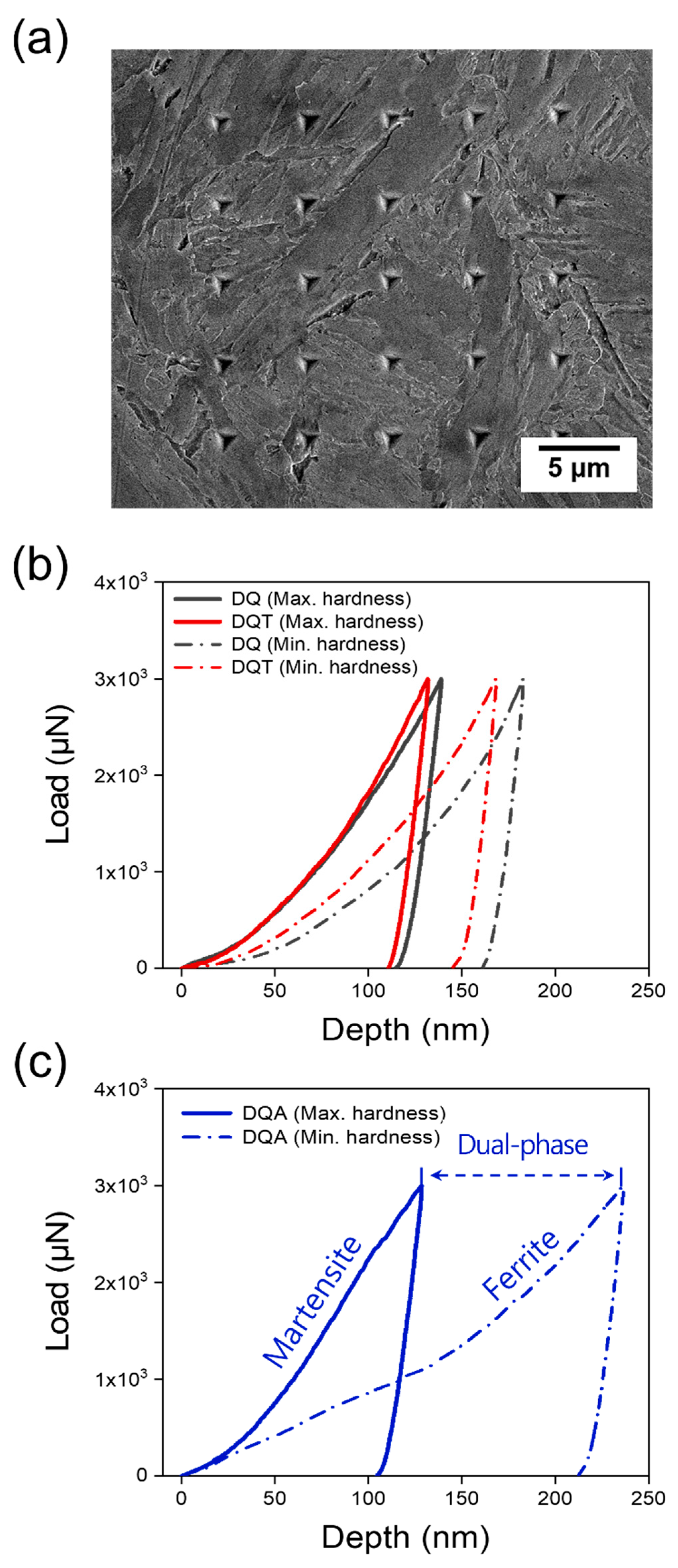
3.2. Nanoindentation Hardness

In this study, 25 (5 × 5) nanoindentations were performed in random areas to confirm the relationship between the microstructure and nanoindentation hardness of the DQ, DQT, and DQA steels. An example of the SEM micrograph after the nanoindentation test was shown in Figure 6a. The average and standard deviation of the nanoindentation hardness were calculated, and the maximum and minimum nanoindentation hardness values of each steel were plotted as load vs. depth curves, as shown in Figure 6b,c. In terms of the average nanoindentation hardness, the DQ steel exhibited the highest value (4.48 GPa ± 0.68), whereas the DQT and DQA steels indicated lower values (4.16 GPa ± 0.42 and 3.88 GPa ± 0.91, respectively). As the dislocation density decreased during tempering, the DQT steel exhibited a lower nanoindentation hardness than the DQ steel. The DQA steel exhibited the lowest nanoindentation hardness among the three steels owing to the introduction of soft ferrite. The three steels can be categorized into two groups based on the standard deviation of the nanoindentation hardness. One group is the DQ and DQT steels with a low standard deviation of nanoindentation hardness (Figure 6b), and the other group is the DQA steel with a high standard deviation of nanoindentation hardness (Figure 6c). Because martensite is highly resistant to deformation as compared with ferrite, the DQA steel with soft ferrite and hard martensite indicated significantly different hardness levels, as shown in Figure 6c.

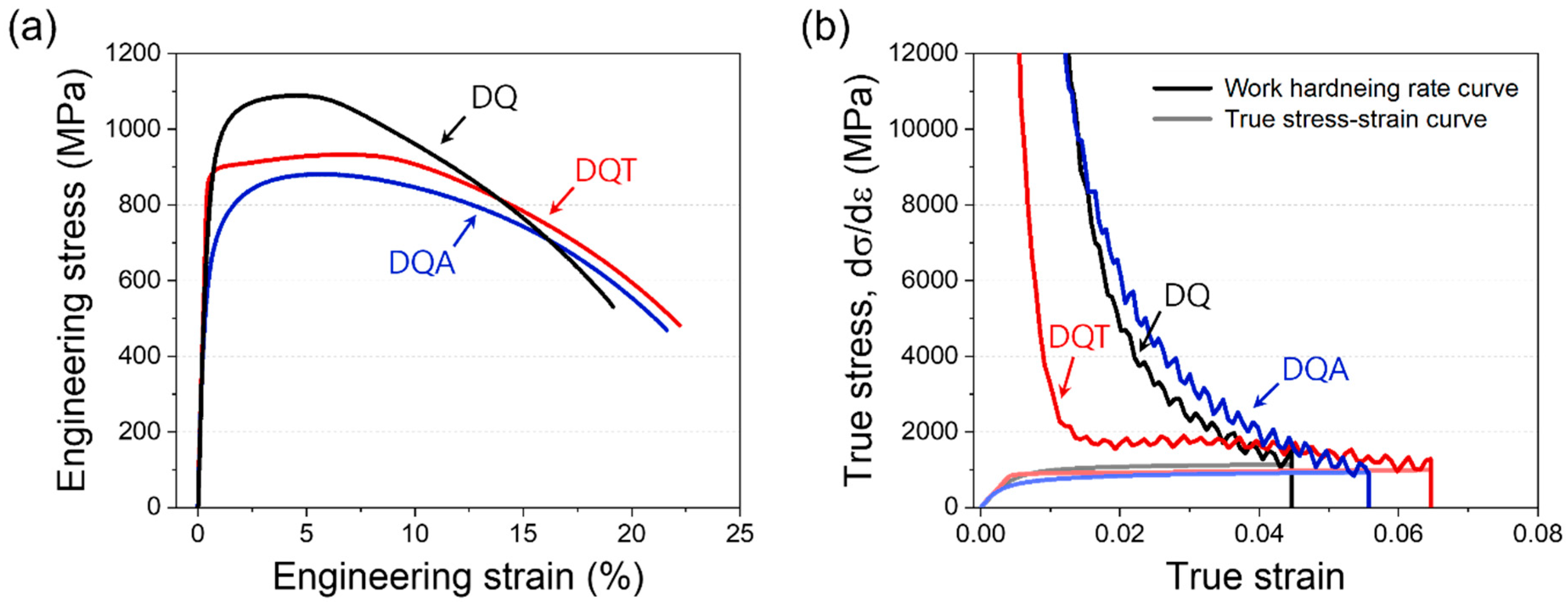
3.3. Tensile Properties

The engineering stress-strain, true stress-strain, and work hardening rate curves of the Fe-0.06C-0.20Si-2.00Mn steels are shown in Figure 7. Meanwhile, the strength, yield-to-tensile strength ratio, total elongation, and work hardening exponent subjected to various heat treatments are summarized in Table 1 based on the curves presented in Figure 7. Among the steels investigated, the DQ steel showed the highest tensile strength (1090 MPa), a relatively low yield-to-tensile strength ratio, and the lowest total elongation (18.9%). The carbon concentration of martensite in the DQ steel decreased owing to carbide precipitation in the well-tempered region, thus resulting in a strength difference between the well-tempered and less-tempered regions. Therefore, it can be inferred that the mixed structure comprising well-tempered hard martensite and less-tempered soft martensite improves the work hardenability during deformation [41].
The yield strength of the DQT steel increased slightly, and the tensile strength decreased by approximately 70 MPa when the DQ steel was tempered at 600 °C for 30 min. The stress required for dislocation motion was increased by carbide precipitation and the pinning of carbides on martensite dislocations during tempering, which consequently enhanced the yield strength [42]. As the supersaturated carbide precipitated and the dislocations recovered uniformly, the strength gradient between the phases decreased, thus causing the work hardening rate to decrease significantly after yielding (Figure 7b). Therefore, the tensile strength remained unchanged and only the yield strength increased, thus resulting in the highest yield-to-tensile strength ratio.
By contrast, among the steels investigated, the DQA steel exhibited the lowest yield strength (606 MPa) and tensile strength (1012 MPa) but showed the best deformability with the lowest yield-to-tensile strength ratio and the highest work hardening rate. For the DQA steel, the soft ferrite introduced by intercritical annealing contributed to the lowest yield strength. Additionally, it is inferred that the high density of mobile dislocations at the interphase (ferrite/martensite) boundary reduces the stress required for the initial yielding (Figure 5). Because the strength of each phase influences the tensile strength of multi-phase steels [43], a dual-phase structure composed of soft ferrite and hard martensite can increase the work hardenability after yielding, thus resulting in a low yield-to-tensile strength ratio and a high work hardening rate. Work hardening caused by the transformation-induced plasticity effect could not be confirmed, which indicates that there was no retained austenite in the DQA steel.

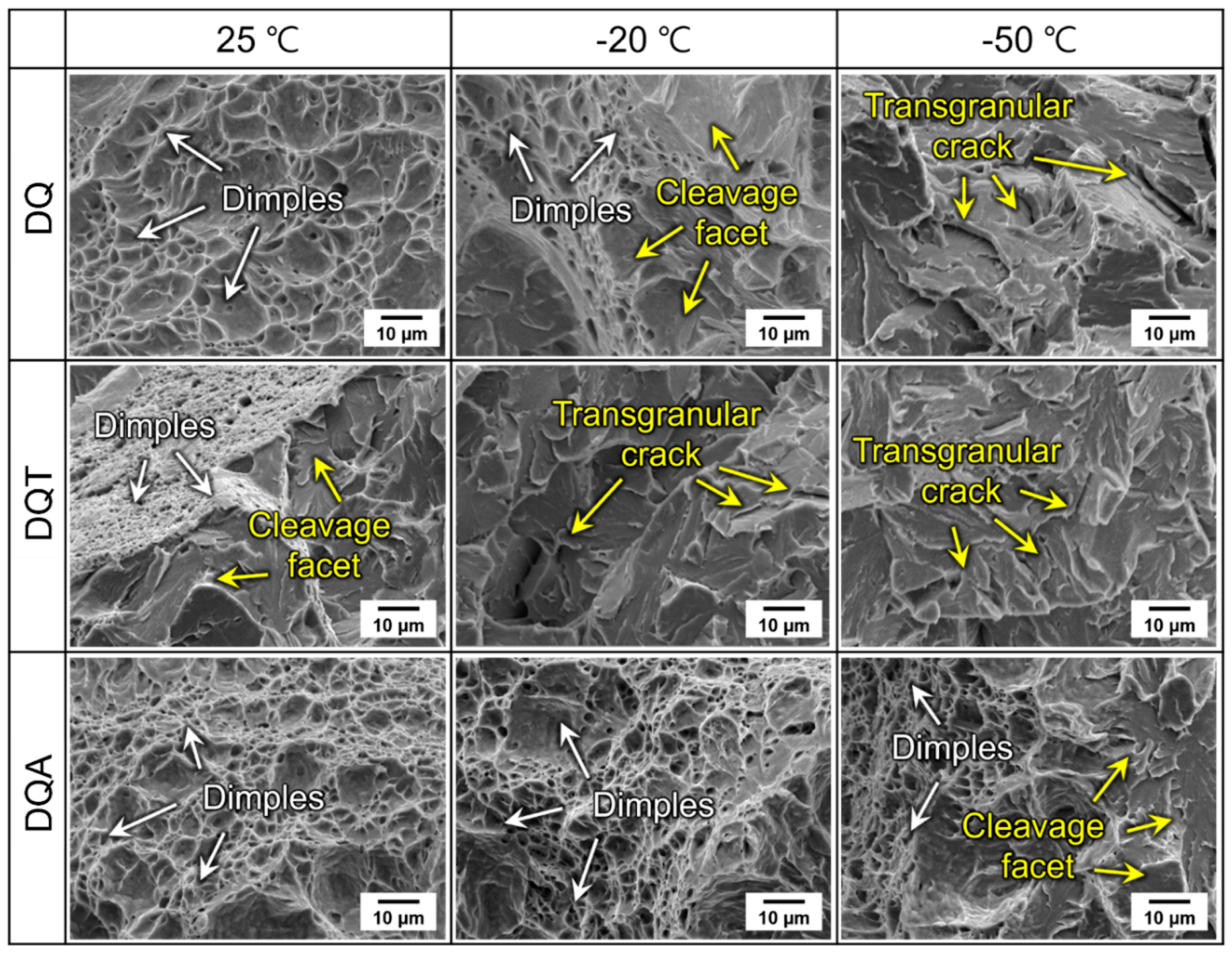
3.4. Ductile-to-Brittle Transition Behavior and Low-Temperature Toughness

The CVN impact test was performed on the DQ, DQT, and DQA steels at a temperature ranging from −196 °C to +25 °C. The absorbed energy curves versus test temperature are fitted with the Boltzmann function, as shown in Figure 8. All three steels showed ductile-to-brittle transition behavior, in which the absorbed energy decreased with decreasing test temperature regardless of the heat treatment methods (Figure 8). The temperature corresponding to one-half of the upper and lower shelf energies in the CVN impact test is defined as the ductile-to-brittle transition temperature (DBTT). The DBTT of the DQ, DQT, and DQA steels is shown in Figure 8. The DQA steel showed the lowest DBTT, whereas the DQT steel had the highest DBTT.
To comprehensively analyze the fracture mode according to the heat treatment method, we examined the fracture surfaces of the impact specimens tested at various temperatures using SEM. Figure 9 shows the fracture surface of the impact specimens tested at 25 °C, −20 °C, and −50 °C for the DQ, DQT, and DQA steels. At room temperature (25 °C), ductile fracture behavior was predominantly observed in the DQ and DQA steels, whereas small dimples and cleavage facets were observed in the DQT steel. For the fracture surface at −20 °C, the DQT steel exhibited completely brittle fracture behavior with transgranular cracks propagating into the ferrite matrix along the cleavage facets, whereas the DQA steel indicated ductile fracture behavior. In the case of the fracture surface at −50 °C, the DQA steel showed a combination of ductile and brittle fracture behaviors, whereas the DQ and DQT steels exhibited the typical cleavage fracture behavior, i.e., flat and river patterns with no traces of plastic deformation. The fracture surface morphologies of the three steels correlated significantly with the absorbed energy, thus indicating that the DBTT of the DQ, DQT, and DQA steels was consistent with the results obtained.
Meanwhile, the DQA steel showed a greater amount of absorbed energy than the DQ and DQT steels regardless of the test temperature. Notably, the DQ and DQT steels exhibited a significant decrease in the absorbed energy below 0 °C, whereas the DQA steel maintained a high level of approximately 200 J even at 0 °C. These results indicate that the intercritical annealing process provides the most effective heat treatment method for improving the low-temperature toughness of Fe-0.06C-0.2Si-2.0Mn steel. The excellent low-temperature toughness of the DQA steel was achieved by increasing the HAGB fraction and fine effective grains by forming reversed austenite during the intercritical annealing process. Greater resistance to crack propagation at low temperatures must be ensured to reduce the DBTT. The HAGB fraction and effective grain size are regarded as one of the most crucial factors in controlling the DBTT of steels and are the basis for low-temperature toughness improvement [4,5]. As the fraction of HAGB increased and the effective grain size decreased, crack propagation was effectively deflected and inhibited, which consequently enhanced the low-temperature toughness. However, the DQT steel showed unsatisfactory low-temperature toughness despite having finer effective grains than the DQ steel because the hard cementite in it served as a crack initiation site. Several researchers reported that precipitated cementite in the ferrite matrix became the initiation site for microcracks when the stress increased, and then these cracks propagated through the ferrite {100} plane [44,45]. Therefore, it can be concluded that tempering process adversely affects low-temperature toughness because the formation of cementite during tempering accelerates crack initiation.

4. Conclusions

In this study, the effects of tempering and intercritical annealing processes on the microstructures and mechanical properties of direct-quenched (DQ) Fe-0.06C-0.2Si-2.0Mn steel were discussed. The DQT steel exhibited a typical tempered martensite structure, and the DQA steel exhibited a dual-phase microstructure comprising soft ferrite and hard martensite and fine grain size owing to the reversed austenite formed during intercritical annealing. Furthermore, it can be confirmed that different microstructures produced by tempering and intercritical annealing processes substantially affected the initial yielding and work hardening behavior during deformation, leading to distinct deformation behaviors. The Charpy V-notch impact test results indicated that the intercritical annealing process is the most suitable heat treatment method to enhance low-temperature toughness. The high fraction of high-angle grain boundaries and fine effective grains suppressed cleavage crack propagation, contributing to the excellent low-temperature toughness of the DQA steel. However, the cementite in the DQT steel adversely affected the low-temperature toughness because it served as a crack initiation site.
In order to ensure the mechanical properties of low-carbon HSLA steels that require different properties, the results of the “structure-property relationship according to the heat treatment method” examined in this study can be utilized as a guide for designing the optimal heat treatment method. Additionally, our further research will present a novel approach to the structure-property relationship by comparing it with various heat treatment methods such as n-step annealing, the flash process, and the thermomechanical control process to further broaden the range of applications for HSLA steels.

Author Contributions

Methodology, S.-H.S. and D.-K.O.; validation, D.-K.O.; formal analysis, S.-H.S.; investigation, S.-H.S.; data curation, S.-H.S. and D.-K.O.; writing—original draft, S.-H.S.; writing—review and editing, B.H.; visualization, D.-K.O.; supervision, B.H.; project administration, B.H.; funding acquisition, B.H. All authors have read and agreed to the published version of the manuscript.

Funding

This research was supported by the Technology Innovation Program (Grant No. 20016064) funded by the Ministry of Trade, Industry and Energy (MOTIE) and by the Basic Science Research Program through the National Research Foundation of the Republic of Korea (NRF-2022R1A2C2004834, NRF-2022R1A4A5033917).

Data Availability Statement

The data presented in this study are available from the corresponding author upon reasonable request. The data are not publicly available due to privacy.

Acknowledgments

The authors are very grateful to Seong-Tak Oh and Yong-Min Hyun of Hyundai Steel Company for providing the HSLA steel.

Conflicts of Interest

The authors declare no conflict of interest.

References

  1. Lee, S.I.; Lee, J.; Hwang, B. Microstructure-based prediction of yield ratio and uniform elongation in high-strength bainitic steels using multiple linear regression analysis. Mater. Sci. Eng. A 2019, 758, 56–59. [Google Scholar] [CrossRef]
  2. Lee, S.I.; Lee, S.Y.; Han, J.; Hwang, B. Deformation behavior and tensile properties of an austenitic Fe-24Mn-4Cr-0.5C high-manganese steel: Effect of grain size. Mater. Sci. Eng. A 2018, 742, 334–343. [Google Scholar] [CrossRef]
  3. Lee, S.I.; Hwang, B. Correlation of microstructure with tensile behavior and properties of API X70 pipeline steels subjected to strain aging. J. Iron Steel. Res. Int. 2020, 27, 319–324. [Google Scholar] [CrossRef]
  4. Hwang, B.; Kim, Y.M.; Lee, S.; Kim, N.J.; Ahn, S.S. Correlation of microstructure and fracture properties of API X70 pipeline steels. Metall. Mater. Trans. A 2005, 36, 725–739. [Google Scholar] [CrossRef]
  5. Hwang, B.; Lee, C.G.; Kim, S.J. Low-Temperature Toughening Mechanism in Thermomechanically Processed High-Strength Low-Alloy Steels. Metall. Mater. Trans. A 2011, 42, 717–728. [Google Scholar] [CrossRef]
  6. Lee, S.Y.; Lee, S.I.; Hwang, B. Effect of strain rate on tensile and serration behaviors of an austenitic Fe-22Mn-0.7C twinning-induced plasticity steel. Mater. Sci. Eng. A 2018, 711, 22–28. [Google Scholar] [CrossRef]
  7. Lee, S.I.; Lee, S.Y.; Lee, S.G.; Jung, H.G.; Hwang, B. Effect of Strain Aging on Tensile Behavior and Properties of API X60, X70, and X80 Pipeline Steels. Met. Mater. Int. 2018, 24, 1221–1231. [Google Scholar] [CrossRef]
  8. Cho, Y.H.; Lee, J.; Choo, W.Y.; Kang, J.; Han, N.H. Effect of Separation on the Fracture Surface of Pipeline Steels with Ferrite–Bainite Dual Phases During Drop Weight Tear Test. Met. Mater. Int. 2022, 28, 1340–1348. [Google Scholar] [CrossRef]
  9. Hong, T.W.; Lee, S.I.; Shim, J.H.; Lee, M.G.; Lee, J.; Hwang, B. Artificial Neural Network for Modeling the Tensile Properties of Ferrite-Pearlite Steels: Relative Importance of Alloying Elements and Microstructural Factors. Met. Mater. Int. 2021, 27, 3935–3944. [Google Scholar] [CrossRef]
  10. Amirjani, N.; Ketabchi, M.; Eskandari, M.; Hizombor, M. Effect of Accelerated Cooling Rate and Finish Rolling Temperature on the Occurrence of Arrowhead Markings in Drop-Weight Tear Test of API 5LX70 Linepipe Nb–V–Ti Steel Plate. Met. Mater. Int. 2021, 27, 4802–4813. [Google Scholar] [CrossRef]
  11. Sohrabi, M.J.; Mirzadeh, H.; Mehranpour, M.S.; Heydarinia, A.; Razi, R. Aging kinetics and mechanical properties of copper- bearing low-carbon HSLA-100 microalloyed steel. Arch. Civ. Mech. Eng. 2019, 19, 1409–1418. [Google Scholar] [CrossRef]
  12. Wang, S.T.; Yang, S.W.; Gao, K.W.; He, X.L. Corrosion behavior and corrosion products of a low-alloy weathering steel in Qingdao and Wanning. Int. J. Miner. Metall. Mater. 2009, 16, 58–64. [Google Scholar] [CrossRef]
  13. Ali, M.; Khosravifard, A.; Hamada, A.; Mattar, T.; Eissa, M.; Komi, J. Promotion of thermomechanical processing of 2-GPa low-alloyed ultrahigh-strength steel and physically based modelling of the deformation behaviour. Mater. Sci. Eng. A 2023, 867, 144747. [Google Scholar] [CrossRef]
  14. Tirumalasetty, G.K.; Huis, M.A.; Fang, C.M.; Xu, Q.; Tichelaar, F.D.; Hanlon, D.N.; Sietsma, J.; Zandbergen, H.W. Characterization of NbC and (Nb, Ti)N nanoprecipitates in TRIP assisted multiphase steels. Acta Mater. 2011, 59, 7406–7415. [Google Scholar] [CrossRef]
  15. Funakawa, Y.; Shiozaki, T.; Tomita, K.; Yamamoto, T.; Maeda, E. Development of High Strength Hot-rolled Sheet Steel Consisting of Ferrite and Nanometer-sized Carbides. ISIJ Int. 2004, 44, 1945–1951. [Google Scholar] [CrossRef]
  16. Yu, Y.; Hu, B.; Gao, M.L.; Xie, Z.; Rong, X.; Han, G.; Guo, H.; Shang, C. Determining role of heterogeneous microstructure in lowering yield ratio and enhancing impact toughness in high-strength low-alloy steel. Int. J. Miner. Metall. Mater. 2021, 28, 816–825. [Google Scholar] [CrossRef]
  17. Xi, X.; Wang, J.; Li, X.; Chen, L.; Wang, Z. The Role of Intercritical Annealing in Enhancing Lowtemperature Toughness of Fe-C-Mn-Ni-Cu Structural Steel. Metall. Mater. Trans. A 2019, 50, 2912–2921. [Google Scholar] [CrossRef]
  18. Calcagnotto, M.; Ponge, D.; Rabbe, D. Ultrafine Grained Ferrite/Martensite Dual Phase Steel Fabricated by Large Strain Warm Deformation and Subsequent Intercritical Annealing. ISIJ Int. 2008, 48, 1011–1096. [Google Scholar] [CrossRef]
  19. Zhou, Y.; Jia, T.; Zhang, X.; Liu, Z.; Misra, R.D.K. Investigation on tempering of granular bainite in an offshore platform steel. Mater. Sci. Eng. A 2015, 626, 352–361. [Google Scholar] [CrossRef]
  20. Frichtl, M.; Anwar, Y.; Strifas, A.; Ankem, S. Improving the Low-Temperature Toughness of a High-Strength, Low-Alloy Steel with a Lamellarization Heat Treatment. Met. Mater. Int. 2023, 29, 879–891. [Google Scholar] [CrossRef]
  21. Zhong, N.; Wang, X.D.; Wang, L.; Rong, Y.H. Enhancement of the mechanical properties of a Nb-microalloyed advanced high-strength steel treated by quenching–partitioning–tempering process. Mater. Sci. Eng. A 2009, 25, 111–116. [Google Scholar] [CrossRef]
  22. Raabe, D.; Sun, B.; Silva, A.K.; Gault, B.; Yen, H.; Sedighiani, S.; Sukumar, P.T.; Filho, I.R.S.; Katnagallu, S.; Jagle, E.; et al. Current Challenges and Opportunities in Microstructure-Related Properties of Advanced High-Strength Steels. Metall. Mater. Trans. A 2020, 51, 5517–5586. [Google Scholar] [CrossRef]
  23. Atreya, V.; Dokkum, J.S.V.; Bos, C.; Santofimia, M.J. Effect of the anisotropy of martensitic transformation on ferrite deformation in Dual-Phase steels. Mater. Des. 2022, 219, 110805. [Google Scholar] [CrossRef]
  24. Park, K.; Nishiyama, M.; Nakada, N.; Tsuchiyama, T.; Takaki, S. Effect of the martensite distribution on the strain hardening and ductile fracture behaviors in dual-phase steel. Mater. Sci. Eng. A 2014, 604, 135–141. [Google Scholar] [CrossRef]
  25. Zhang, J.; Di, H.; Deng, Y.; Misra, R.D.K. Effect of martensite morphology and volume fraction on strain hardening and fracture behavior of martensite–ferrite dual phase steel. Mater. Sci. Eng. A 2015, 627, 230–240. [Google Scholar] [CrossRef]
  26. Atreya, V.; Bos, C.; Santofimia, M.J. Understanding ferrite deformation caused by austenite to martensite transformation in dual phase steels. Scr. Mater. 2021, 202, 114032. [Google Scholar] [CrossRef]
  27. Wang, J.; Li, W.; Zhu, X.; Zhang, L. Effect of martensite morphology and volume fraction on the low-temperature impact toughness of dual-phase steels. Mater. Sci. Eng. A 2022, 832, 142424. [Google Scholar] [CrossRef]
  28. Zhang, C.-Y.; Wang, Q.-F.; Kong, J.-L.; Xie, G.-Z.; Wang, M.-Z.; Zhang, F.-C. Effect of martensite morphology on impact toughness of ultra-high strength 25CrMo48V steel seamless tube quenched at different temperatures. J. Iron Steel Res. Int. 2013, 20, 62–67. [Google Scholar] [CrossRef]
  29. ASTM E8/E8M-08; Standard Test Methods for Tension Testing of Metallic Materials. ASTM International: West Conshohocken, PA, USA, 2008.
  30. Colla, V.; De Sanctis, M.; Dimatteo, A.; Lovicu, G.; Solina, A.; Valentini, R. Strain hardening behavior of dual-phase steels. Metall. Mater. Trans. A 2009, 40, 2557–2567. [Google Scholar] [CrossRef]
  31. ASTM E23–16b; Standard Test Methods for Notched Bar Impact Testing of Metallic Materials, ASTM Book of Standards. ASTM International: West Conshohocken, PA, USA, 2016.
  32. Morsdorf, L.; Tasan, C.C.; Ponge, D.; Raabe, D. 3D structural and atomic-scale analysis of lath martensite: Effect of the transformation sequence. Acta Mater. 2015, 95, 366–377. [Google Scholar] [CrossRef]
  33. Babu, S.R.; Nyyssonen, T.; Jaskari, M.; Jarvenpaa, A.; Davis, T.P.; Pallaspuro, S.; Komi, J.; Porter, D. Observations on the Relationship between Crystal Orientation and the Level of Auto-Tempering in an As-Quenched Martensitic Steel. Metals 2019, 9, 1255. [Google Scholar] [CrossRef]
  34. Krauss, G. Tempering of Lath Martensite in Low and Medium Carbon Steels: Assessment and Challenges. Steel Res. Int. 2017, 88, 170038. [Google Scholar] [CrossRef]
  35. Chakraborti, P.C.; Mitra, M.K. Microstructure and tensile properties of high strength duplex ferrite–martensite (DFM) steels. Mater. Sci. Eng. A 2007, 466, 123–133. [Google Scholar] [CrossRef]
  36. Brands, D.; Balzani, D.; Scheunemann, L.; Schroder, J.; Richter, H.; Raabe, D. Computational modeling of dual-phase steels based on representative three-dimensional microstructures obtained from EBSD data. Arch. Appl. Mech. 2016, 86, 575–598. [Google Scholar] [CrossRef]
  37. Ryde, L. Application of EBSD to analysis of microstructures in commercial steels. Mater. Sci. Technol. 2006, 22, 1297–1306. [Google Scholar] [CrossRef]
  38. Chang, Y.; Lin, M.; Hangen, U.; Richter, S.; Haase, C.; Bleck, W. Revealing the relation between microstructural heterogeneities and local mechanical properties of complex-phase steel by correlative electron microscopy and nanoindentation characterization. Mater. Des. 2021, 203, 109620. [Google Scholar] [CrossRef]
  39. Matsuno, T.; Ando, R.; Yamashita, N.; Yokota, H.; Goto, K.; Watanabe, I. Analysis of preliminary local hardening close to the ferrite–martensite interface in dual-phase steel by a combination of finite element simulation and nanoindentation test. Int. J. Mech. Sci. 2020, 180, 105663. [Google Scholar] [CrossRef]
  40. Khosravani, A.; Caliendo, M.C.; Kalidindi, S.R. New Insights into the Microstructural Changes During the Processing of Dual-Phase Steels from Multiresolution Spherical Indentation Stress–Strain Protocols. Metals 2020, 10, 18. [Google Scholar] [CrossRef]
  41. Matsuda, H.; Mizuno, R.; Funakawa, Y.; Seto, K.; Matsuoka, S.; Tanaka, Y. Effects of auto-tempering behaviour of martensite on mechanical properties of ultra high strength steel sheets. J. Alloys Compd. 2013, 577, 661–667. [Google Scholar] [CrossRef]
  42. Shin, S.H.; Yoon, Y.C.; Lee, S.I.; Hwang, B. Improvement in Low-Temperature Toughness of Fe-6.5Mn-0.08C Medium-Mn Steel by Multi-Step Heat Treatment. J. Mater. Res. Technol. 2023, 26, 3558–3570. [Google Scholar] [CrossRef]
  43. Bag, A.; Ray, K.K. A new model to explain the unusual tensile behavior of high martensite dual-phase steels. Metall. Mater. Trans. A 2001, 32, 2400–2403. [Google Scholar] [CrossRef]
  44. Shin, S.H.; Oh, D.K.; Yoon, Y.C.; Hwang, B. Correlation of Microstructure with Anisotropy of Low-Temperature Toughness in Two API X70 Pipeline Steels. Steel Res. Int. 2023, 94, 2200429. [Google Scholar] [CrossRef]
  45. Gladman, T.; Pickering, F.B. The Effect of Grain Size on the Mechanical Properties of Ferrous Materials. In Yield, Flow and Fracture of Polycrystals; Baker, T.N., Ed.; Applied Science Publishers: London, UK; New York, NY, USA, 1982. [Google Scholar]
Figure 1. Schematic illustration of heat treatments of the DQ, DQT, and DQA steels. DQ: direct quenching after hot rolling, DQA: intercritical annealing after direct quenching, DQT: tempering after direct quenching.
Metals 13 01912 g001
Figure 2. Scanning electron microscope (SEM) micrographs of the (a,b) DQ, (c,d) DQT, and (e,f) DQA steels. Enlarged SEM micrographs of the (b) DQ, (d) DQT, and (f) DQA steels represented by the white dashed box in Figure 2a, Figure 2c and Figure 2d, respectively. DQ: direct quenching after hot rolling, DQA: intercritical annealing after direct quenching, DQT: tempering after direct quenching.
Metals 13 01912 g002
Figure 3. Electron back-scattered diffraction (EBSD) inverse pole figure (IPF) maps of the (a) DQ, (b) DQT, and (c) DQA steels. Prior austenite grain boundaries are marked by white lines in Figure 3a,b, and newly formed grains are indicated by white arrows in Figure 3c. Prior austenite grain boundaries are highlighted at a misorientation angle of 20~45° using TSL-OIM software. The effective grain sizes of the DQ, DQT, and DQA steels were measured to be 13.8, 11.6, and 10.0 μm, respectively, which correspond to grains with misorientation angles of 15° or more [4,5]. DQ: direct quenching after hot rolling, DQA: intercritical annealing after direct quenching, DQT: tempering after direct quenching.
Metals 13 01912 g003
Figure 4. The distribution of grain boundary misorientation in DQ, DQT, and DQA steels denoted the number fraction of the low-angle grain boundary (LAGB) and high-angle grain boundary (HAGB) obtained from electron back-scattered diffraction (EBSD) analysis. DQ: direct quenching after hot rolling, DQA: intercritical annealing after direct quenching, DQT: tempering after direct quenching.
Metals 13 01912 g004
Figure 5. Electron channeling contrast imaging (ECCI) images of the (a) DQ and (b) DQA steels. DQ: direct quenching after hot rolling, DQA: intercritical annealing after the direct quenching.
Metals 13 01912 g005
Figure 6. (a) Example of scanning electron microscope (SEM) micrograph of the DQA steel after nanoindentation test. The corresponding load–depth curves for the maximum and minimum nanoindentation hardness of (b) DQ, DQT, and (c) DQA steels. The average nanoindentation hardnesses (GPa) of DQ, DQT, and DQA steels are 4.48 GPa ± 0.68, 4.16 GPa ± 0.42, and 3.88 GPa ± 0.91, respectively. DQ: direct quenching after hot rolling, DQA: intercritical annealing after direct quenching, DQT: tempering after direct quenching.
Metals 13 01912 g006
Figure 7. (a) Room temperature engineering stress-strain and (b) true stress-strain and work hardening rate curves for DQ, DQT, and DQA steels. DQ: direct quenching after hot rolling, DQA: intercritical annealing after direct quenching, DQT: tempering after direct quenching.
Metals 13 01912 g007
Figure 8. Charpy impact absorbed energy plotted as a function of test temperatures from −150 °C to +25 °C for DQ, DQT, and DQA steel. DQ: direct quenching after hot rolling, DQA: intercritical annealing after direct quenching, DQT: tempering after direct quenching.
Metals 13 01912 g008
Figure 9. Scanning electron microscope (SEM) fractographs of the Charpy impact specimens tested at −50, −20, and +25 °C for DQ, DQT, and DQA steels. Each fracture mode is denoted in Figure 9. DQ: direct quenching after hot rolling, DQA: intercritical annealing after direct quenching, DQT: tempering after direct quenching.
Metals 13 01912 g009
Table 1. The tensile properties of DQ, DQT, and DQA steels. The work hardening exponent (n) is calculated using the Hollomon equation [30]. DQ: direct quenching after hot rolling, DQA: intercritical annealing after direct quenching, DQT: tempering after direct quenching.
SteelYield
Strength,
(MPa)
Tensile
Strength,
(MPa)
Yield-to-Tensile Strength RatioTotal Elongation
(%)
Work
Hardening
Exponent (n)
DQ862 ± 31090 ± 200.79 ± 0.0018.9 ± 0.20.13 ± 0.00
DQT879 ± 7962 ± 90.94 ± 0.0021.0 ± 2.60.05 ± 0.00
DQA606 ± 6892 ± 60.68 ± 0.0121.7 ± 0.10.17 ± 0.01
Disclaimer/Publisher’s Note: The statements, opinions and data contained in all publications are solely those of the individual author(s) and contributor(s) and not of MDPI and/or the editor(s). MDPI and/or the editor(s) disclaim responsibility for any injury to people or property resulting from any ideas, methods, instructions or products referred to in the content.

