Article

Study on the Microstructure and Mechanical Properties of Ultrasonic-Assisted TIG Welded 441 Ferritic Stainless Steel Joints

1
Key Laboratory of Automobile Materials, School of Materials Science and Engineering, Jilin University, Changchun 130025, China
2
School of Mechanical and Aerospace Engineering, Jilin University, Changchun 130025, China
*
Authors to whom correspondence should be addressed.
Metals 2023, 13(12), 1924; https://doi.org/10.3390/met13121924
Submission received: 16 October 2023 / Revised: 17 November 2023 / Accepted: 20 November 2023 / Published: 22 November 2023
(This article belongs to the Section Welding and Joining)

Abstract

:
A self-designed ultrasonic-assisted welding platform was built to improve the poor microstructure and properties of conventional TIG welded ferritic stainless steel. The ultrasonic vibration was transmitted to the weld pool through the base metal in the manner of point–surface contact in the optimal position after calculation. The results show that the coarse columnar grains in the welded joint can be transformed into very fine equiaxed grains under ultrasonic vibration, especially the coarse columnar grains near the fusion line where cliff-like refinement occurs. The maximum grain size in the weld seam is reduced from 420 μm to 260 μm, and the average size is reduced by 60%. At the same time, the grain orientation tends to be harmonized. The microhardness of the welded joint is greatly improved on the whole, and the softening of the heat-affected zone caused by grain coarsening is effectively inhibited. Compared with the welded joints without ultrasonic assistance, the tensile strength and yield strength can be increased by 61 MPa and 47 MPa, respectively, under 130 W ultrasonic vibration. By strengthening the weak part of the welded joint, the weldability and toughness reserve of 441 ferritic stainless steel can be significantly improved.

1. Introduction

Nowadays, ferritic stainless steel (FSS) is widely used in automobiles, railway vehicles, etc., due to its excellent mechanical properties and low corrosion sensitivity [1,2,3,4]. However, the weldability of ferritic stainless steel is poor. The grains in the welded joints are very coarse with insufficient toughness reserves, causing cracking failure in the subsequent forming process.
Researchers have completed many scientific experiments on welding methods and procedures to solve the above problem [5,6,7]. For instance, Amuda et al. used low-temperature cooling treatment to change the growth trend of grains in FSS welded joints. The rapid cooling of the welded joint inhibited the growth rate of grains, and the grain size was reduced by 45% [8]. However, this rapid cooling method is unreliable in engineering applications. Taban et al. proposed a composite welding technology for FSS. They used PAW + GTA as a composite welding heat source and obtained welded joints with good mechanical properties. However, the coupling of heat sources in this composite welding technology is not stable enough [9]. Lakshminarayanan et al. studied the microstructure and properties of FSS welded joints prepared via friction stir welding. They found that the welded joints without a metallurgical reaction had a small grain size in the weld zone and no significant grain growth occurred in the heat-affected zone [10]. Some research focused on metallurgical reactions and post-welding heat treatment, such as adding alloying elements to intervene in the nucleation process of the welding pool, thus improving the microstructure of welded joints by promoting heterogeneous nucleation. However, these methods are not conducive to the mass production of weldparts due to their complexity [11,12].
Among the welding methods used for FSS in actual industry, GTAW (TIG) has the advantages of a stable arc, a low welding heat input, a smaller heat-affected zone and a low cost compared with SMAW, CMT and other methods [2,13,14]. Mohandas et al. studied the effects of gas tungsten welding and arc welding on the structure and properties of FSS welded joints. They found that equiaxed grains were formed in the weld zone of gas tungsten welding, which improved the strength and plasticity of welded joints to a certain extent compared with arc welding [15]. However, the grains in weld zones with a high Cr content were still coarsened. To address this issue, Wang et al. constructed a three-dimensional finite element model to determine the main factors affecting the FSS TIG welding effect, and it was proved that simulating before welding and controlling its thermal cycle process can effectively reduce the grain size and improve the performance of welded joints [16]. Therefore, it can be seen that GTAW is suitable for welding FSS, but it is still necessary to make technical improvements around this welding method.
The above research improved the microstructure and mechanical properties of FSS welded joints by regulating the welding process, material composition and heat treatment process. There is an urgent need to develop a welding technology that can get rid of the limitations of the above research objects and obtain ideal welded joints to resist brittle cracking. The ultrasonic cavitation effect is often accompanied by mechanical effects, thermal effects and chemical effects, which can be applied in current welding technologies to provide more obvious advantages [17,18,19,20]. The ultrasonic coupling methods generally include high-frequency current excitation and external ultrasonic power supply regulation. For high-frequency current excitation, one method involves controlling the pulse frequency of the welding power supply so as to output ultrasonic excitation through the arc. The other method involves superimposing a high-frequency alternating arc supplied by external ultrasonic excitation on the stable burning arc through the coupling of the transmission line [21,22,23,24,25]. Morisada et al. developed a high-frequency tungsten inert gas welding method and studied the welding effect at a frequency of 10–40 kHz. Compared with traditional TIG welding of 60 Hz, the porosity area was reduced by one-eighth [21]. Yet, the high-frequency pulse power supply has higher requirements for the equipment and can only be realized in TIG welding. Hence, researchers began to focus on the method of applying high-frequency vibration directly to the weld pool through an ultrasonic generating device, and gradually developed a series of ultrasonic-assisted welding technologies.
The ultrasonic vibration can act on the base metal, arc, filled metal and weld pool. Wu et al. applied ultrasonic vibration on the base metal directly while performing the TIG welding-brazing joining of an aluminum alloy to steel. Compared with the joints without ultrasonic vibration, the tensile shear strength of joints with ultrasonic vibration was increased by about 30% and the macro forming of the weld seam was also optimized [26]. Dai directly applied ultrasonic vibration to the base metal of 7075-T6 aluminum alloy through the tool head of a high-intensity ultrasonic emitter, and found that the cooling time and cooling speed of weld pool were improved. Also, the weld penetration depth, grain refinement and hardness can be increased with appropriate parameters [27]. Chen et al. applied ultrasonic–arc coaxial technology to the welding of Q235 stainless steel, and proved that the texture type was changed and the texture strength was decreased under the action of ultrasound. In addition, the crystal isotropy was improved, and the hardness was increased by about 30 HV [28]. Sun et al. applied the ultrasonic–arc coaxial composite technology to TIG (U-TIG), and the experimental results showed that when ultrasonic vibration acted on the arc, the arc thrust was enhanced, and the weld penetration depth was increased by 300% [29]. Xie et al. successfully prepared dissimilar alloy joints with an Al coating while studying the ultrasonic spot welding of Ti6Al4V/TiNi [30]. Watanbe proposed the ultrasonic–wire composite welding technology to transfer ultrasonic vibration energy through the forward moving welding wire, and obtained equiaxed crystals in the weld zone [31].
It can be seen that the method of conducting ultrasonic vibration through the base metal can be flexibly applied to different welding methods, and it is much easier to achieve in terms of equipment and welding parameter adjustment. Nevertheless, the current application is mostly achieved by inputting violent vibration energy into the whole weldments with the aid of a high-power ultrasonic generator, which often requires large equipment and welding tools to support the entire system. However, the equipment will be exposed to strong vibration interference in long-term welding work, resulting in the reduction in service life. Therefore, establishing how to make the whole welding system more stable and establishing how to make the utilization of the ultrasonic energy field more effective are the main problems that need to be resolved.
In view of the fact that there is an urgent need to improve the microstructure and mechanical properties of FSS welded joints, the present work first built a flexible ultrasonic-assisted TIG welding system with an optimized input point of ultrasonic vibration into the base metal, and then investigated in detail the microstructure and mechanical properties of a 441 FSS welded joint prepared via this welding system to reveal the improvement mechanism as well as to optimize the parameters of this self-built ultrasonic-assisted welding system.

2. Experimental

2.1. Materials and Test Methods

The 441 ferritic stainless steel was chosen as the base metal in the present work. Its chemical composition and mechanical properties are shown in Table 1 and Table 2, respectively. A 441 ferritic stainless steel plate was welded using the special ultrasonic-assisted tungsten argon arc welding method proposed in this work. Samples with dimensions of 25 mm × 5 mm × 2 mm were then cut from the welded joint for microstructure characterization. Sequential grinding, polishing and etching were carried out on the cross sections of the samples for OM (Zeiss Scope A1) analysis. The etching solution was a ferric chloride–hydrochloric acid solution (96 mL H2O + 24 mL HCl + 10 g FeCl3), and the etching time was 3 min. In order to further analyze the influence of ultrasonic-assisted tungsten argon arc welding on the grain size and grain growth orientation of the welded joint, the electron backscattering technique (EBSD) was also adopted. Before EBSD detection, electrolytic polishing was conducted on the mechanically polished samples with a low-temperature electrolyte that was cooled in a −20 °C liquid nitrogen environment. The electrolytic polishing process was completed at a constant voltage of 20 V and lasted for 10 s. The electrolyte was a perchloric acid–alcohol solution with the specific composition configured as 10 mL HClO4 + 90 mL alcohol.
Considering the narrow space of a welded joint and the non-uniformity of its microstructure, the microhardness distribution of welded joints was measured using a MH-3 Vickers hardness tester with a test load of 200 g, a holding time of 10 s and a test interval of 0.5 mm. The same tests were repeated three times for each group of samples and the average values were finally adopted.
The tensile test was carried out on an MTS-810 electro-hydraulic servo testing machine with a tensile rate of 1 mm/min. Figure 1 shows the shape and dimension of the tensile sample, which was sampled along the weld seam (the gray part) according to GB/T 228 standard [32]. The yield strength, tensile strength and elongation were characterized by the average value of three tensile samples.

2.2. Ultrasonic-Assisted Tungsten Argon Arc Welding Process

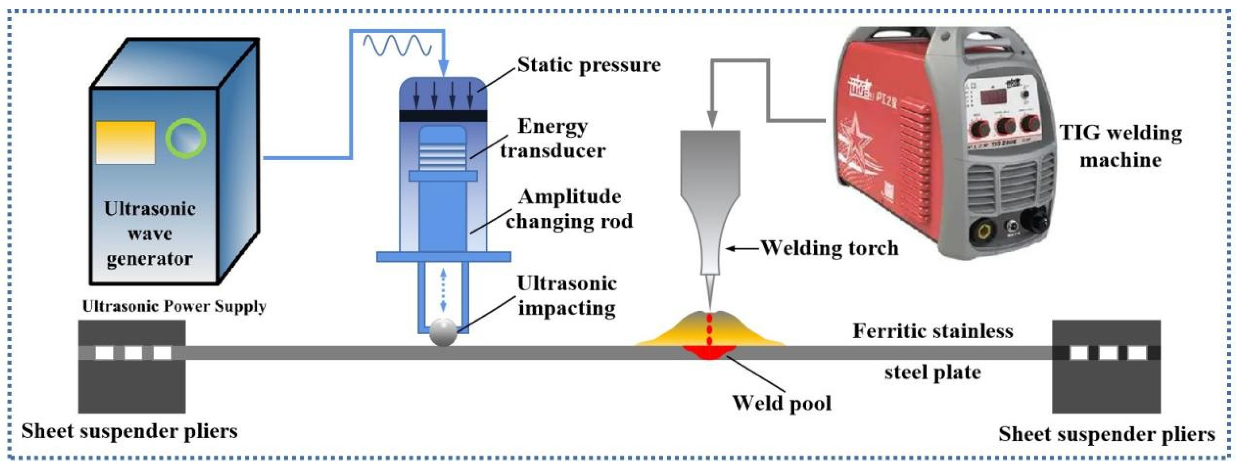
The special ultrasonic-assisted tungsten argon arc welding process was implemented using a self-built ultrasonic-assisted welding system which consisted of a welding device, a ultrasonic vibration device and a welding fixture, as shown in Figure 2. A TIG-250E inverter DC argon arc welding machine was chosen as power the source with high-purity argon as the shielding gas. Ultrasonic vibration was generated by the ultrasonic power supply, converted using the tool system and finally transferred into the base material through the spherical tool head in the form of a point–surface contact.
The vibration wave propagated from the contact point to the base metal. During wave propagation, a stationary wave is generated by the superposition of the propelling wave and reflected wave, causing violent disturbances in the local region. The fine sand grain beating method was adopted to measure the vibration mode so as to find the position of the node line and the severe vibration region. Through measurement, the ultrasonic wave source was applied at a position 20 mm away from the welding torch and was moved synchronously in the direction parallel with the weld seam, so that the welding pool metal solidified under the largest ultrasonic vibration.

3. Results and Discussion

3.1. Microstructure of Welded Joint Prepared via Ultrasonic-Assisted Welding

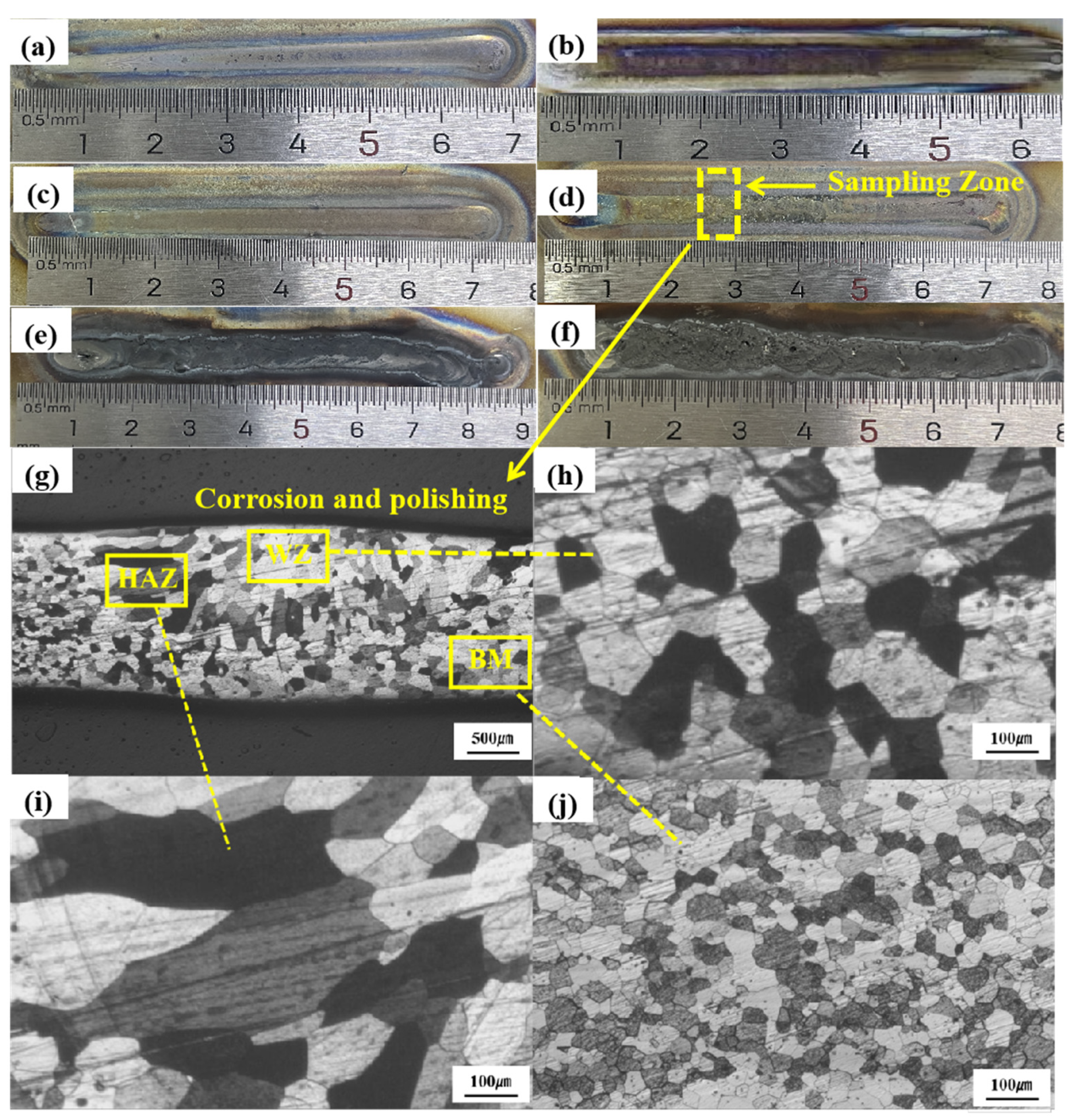
For the tungsten argon arc welding adopted in this work, the welding current is the most important factor affecting the size, appearance and microstructure of the weld joint, as too large a welding current will generate defects such as burning through, and too small a welding current will lead to insufficient heat input, causing defects such as non-fusion. Thus, before introducing ultrasonic vibration into welding, the welding current was optimized to obtain the best ultrasonic-assisted welding quality. The macroscopic morphologies of weld joints were first compared to make a preliminary judgment. Figure 3a–f show the macro-morphologies of the weld seam with the welding current varying from 90 A to 65 A under a 6 mm/s welding speed and 15 L/min of protecting gas flow rate. It can be seen from Figure 3a,b that obvious surface defects were generated under welding currents of 90 A and 85 A. The weld seam is discontinuous, which seriously worsens the surface quality of the welded joint. This may be due to the excessive heat input caused by the overly high welding current. When the welding current was set between 80 A and 65 A, aesthetic formation can be obtained. The weld seam is straight and smooth in Figure 3c–f without obvious defects. However, when the welding current is below 60 A, the width of the weld seam significantly decreases. This is because the welding heat input is proportional to the welding current according to the empirical equation Q = (η′U × I)/λ, where Q is the heat input, η is the efficiency, U is the welding voltage, I is the welding current, and λ is the welding speed. When the current is too low, the heat input is not high enough, resulting in a decrease in the width of the weld seam.
In view of the impossibility of judging properties based on appearance, subsequent microstructure and property analyses were conducted. Figure 3g reveals the cross-sectional microstructure of the welded joint obtained under 65 A. As observed, equiaxed grains were formed only in a very small region in the center of the weld seam (WS). The remaining area of the welded joint including the heat-affected zone (HAZ) consists of very coarse columnar grains with sizes up to several hundred microns, seriously deteriorating the plasticity and toughness of the welded joint. Moreover, the size of the equiaxed grains in the weld center is quite large, several times larger than that of the base metal (BM), which also negatively affects plasticity and toughness.
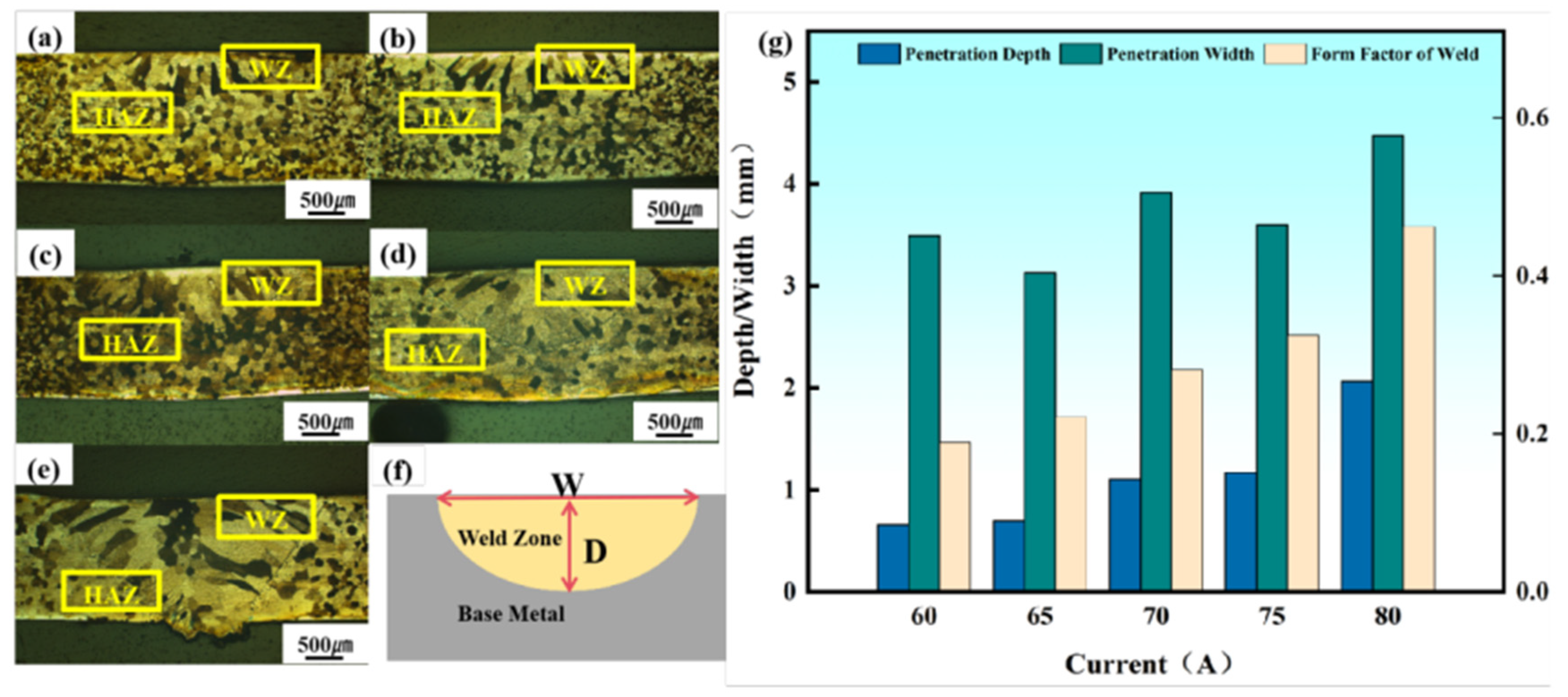
Further comparative analysis was carried out among the samples with good weld formation to study the influence of the welding current on the forming characteristics including melting depth, melting width and their ratio as well as the size of the microstructure. It can be seen from Figure 4a–e that the metallographic structure of the welded joint under different welding currents presents visible differences. As the welding current rises, the penetration depth increases gradually. When the current increases from 60 A to 75 A, the penetration depth changes from 0.67 mm to 1.17 mm, increasing by 74.6%. The form factor, which is the ratio of the penetration depth and the penetration width, also increases with the increase in the welding current, indicating that the forming quality of the weld seam improves. In addition, the melting width fluctuates slightly with an overall increasing trend, as shown in Figure 4g. The evolution of the metallographic structure is not completely consistent with the forming characteristics. When the welding current drops from 80 A, the equiaxed grains in the weld center have a tendency to increase, but the coarse columnar grains are not significantly improved and become even larger. When welding current drops to 70 A, the number of equiaxed grains in the weld center increases and the coarse columnar grains are inhibited to a certain extent. With a further decrease in current, the microstructure cannot be improved further. On the contrary, the columnar grains show an increasing trend, and the equiaxed crystals in the weld center also present a growing trend.
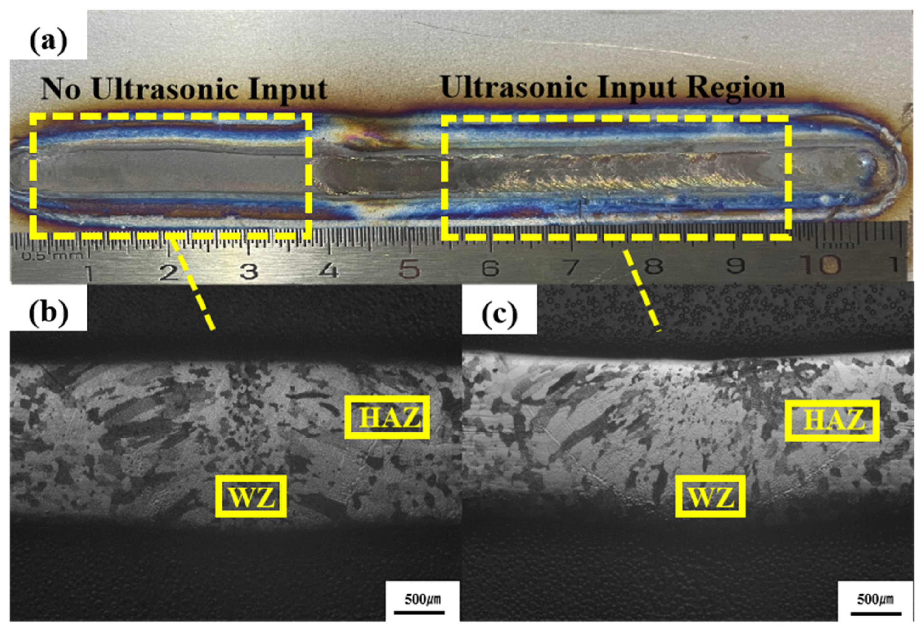
Based on the above experimental results, a welding current of 70 A was selected to conduct the comparative test of conventional TIG welding and ultrasonic-assisted TIG welding. In Figure 5a, the macro appearance of the ultrasonic-assisted weld seam is presented, as well as that of the conventional weld seam. The slight fish scale effect on the surface of ultrasonic-assisted weld seam reflects the stirring effect of ultrasonic vibration on the weld pool, which also suggests the higher strength of the welded joint. Figure 5b,c show a clear difference in microstructure. The weld seam and heat-affected zone are distinctly changed under the action of ultrasonic wave. When solidified without ultrasonic vibration, the grains in the weld pool grow along the direction nearly parallel to the surface, and present an obvious coarse columnar appearance. Equiaxed grains are distributed in a very narrow range along the center line of the weld seam in the depth direction. With the assistance of ultrasonic vibration, nucleation points increase significantly under the ultrasonic cavitation effect generated in the weld pool, making the microstructure appear as very fine equiaxed crystals after solidification. The distribution range of the equiaxed grains is obviously enlarged and in harmony with the shape of the weld pool. The grains are extremely small, meaning that grain boundaries can no longer be seen under an optical microscope. Meanwhile, the grains close to the fusion line are a little larger than the equiaxed grains in the weld center. A few grains present a columnar shape, but the growth orientation is much more evenly distributed towards the heat source. The metallographic structure of the welded joint before and after ultrasonic induction indicates that the columnar crystals in the weld seam largely disappear and the grain size is obviously improved by ultrasonic vibration.
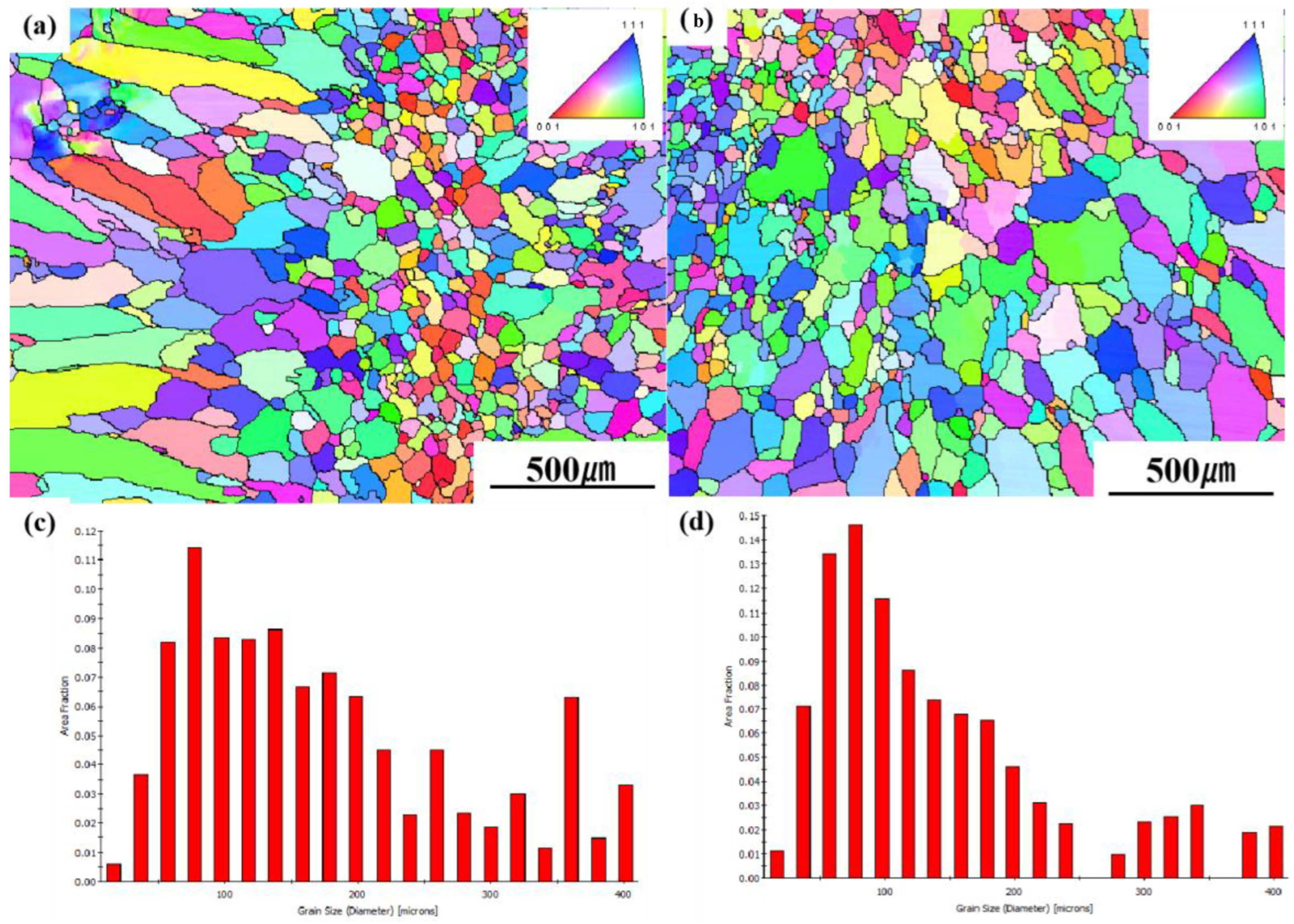
The effects of ultrasonic vibration on grain size, grain size distribution and grain orientation were further analyzed through EBSD. Figure 6 shows the microstructure of the entire region containing the weld seam and the heat-affected zone. Grains in all regions of the welded joint are refined under the action of ultrasonic vibration. The refinement near the fusion line is the most obvious, not only reflected in the decrease in grain size, but also in the transformation from a columnar morphology to an equiaxed morphology. The grain size of the conventional welded joint varies from 20 μm to 400 μm, and grains between 100 μm and 400 μm in size are more common than in the ultrasonic-assisted welded joint. Meanwhile, for the latter, grains smaller than 100 μm are significantly increased in prevalence. Meanwhile, the coarse columnar grains in the conventional welded joint occupy a large proportion of the grains, and their orientation is relatively homogeneous. Here, any grain boundary greater than 15° is considered to be a high-angle boundary. After introducing ultrasonic vibration into welding, the grain orientation of the entire welded joint becomes more random, which is very advantageous for resisting brittle fractures in ferrite welded structures.
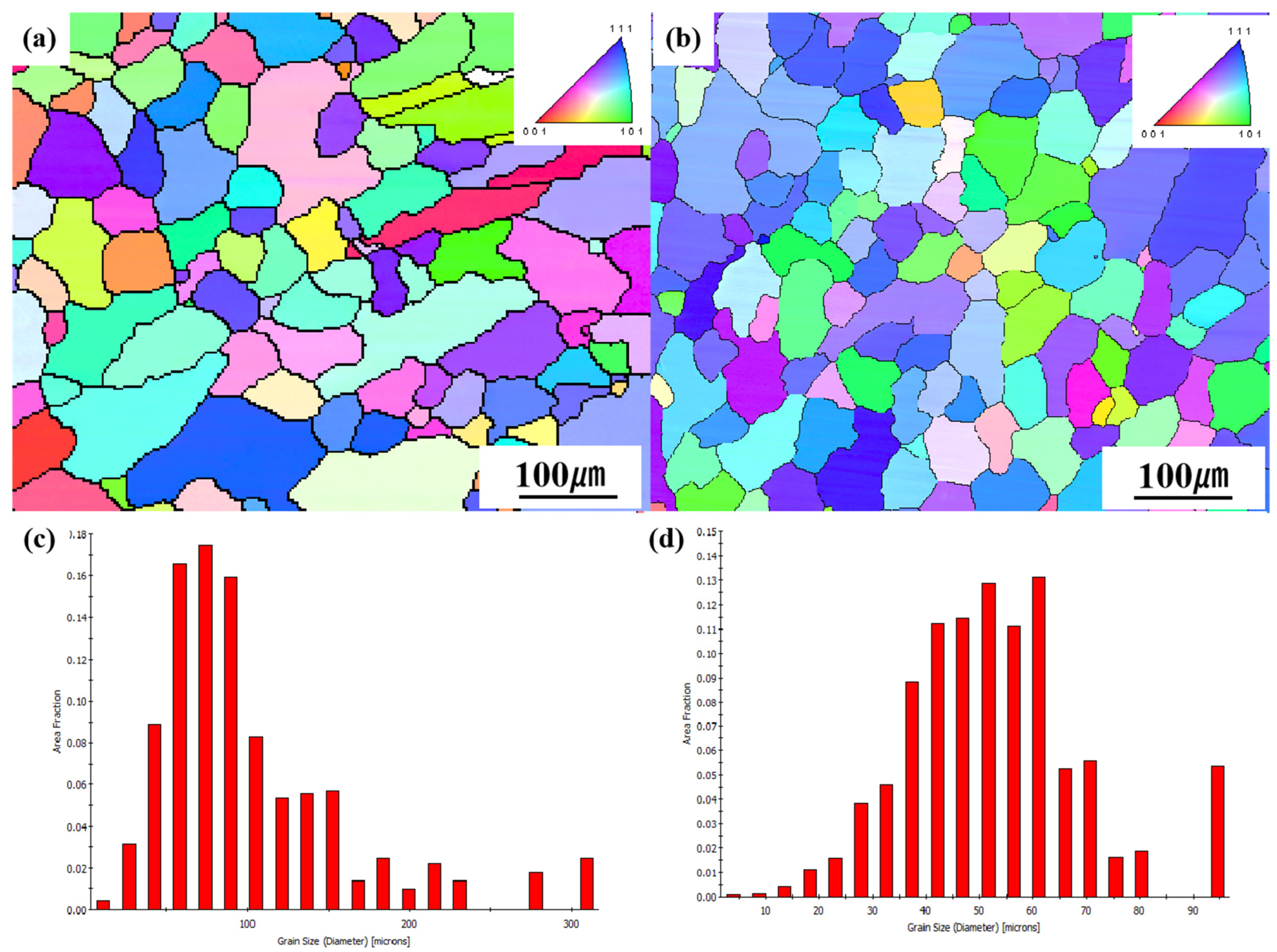
For a clear and detailed comparison, EBSD results of different regions in the welded joint were analyzed separately. Figure 7 shows the microstructure near the weld center. It can be observed that although equiaxed grains were found in both kinds of welded joints, the distribution range in the conventional welded joint is only within 600 μm along the transverse direction. When this range is exceeded, grains grow into coarse columnar grains rapidly. On the contrary, equiaxed grains in the ultrasonic-assisted welded joint almost spread throughout the weld seam, and the size is fairly uniform, with a slight increase from the weld center to both sides. Moreover, the size of equiaxed grains in the conventional welded joint is relatively larger compared with in the ultrasonic-assisted welded joint. The grain size of the conventional welded joint sample varies from 20 μm to 310 μm. Most grains have a size between 40 μm and 150 μm, and more than 50% of the grains are greater than 100 μm in size. Meanwhile, the grains of the ultrasonic-assisted welded joint sample range in size from 5 μm to 105 μm, and about 54% of the grains are less than 50 μm in size, with the remaining grains also less than 100 μm in size. In addition, the maximum grain size of the former is 309.15 μm, and the average grain size is 102.7 μm. As for the latter, the maximum grain size and average grain size are reduced to 94.5 μm and 52.8 μm, respectively. It is also worth noting that most grains are between 30 μm and 60 μm in size. Thus, the grain size of the entire ultrasonic-assisted weld seam is at least half that of the conventional weld seam.
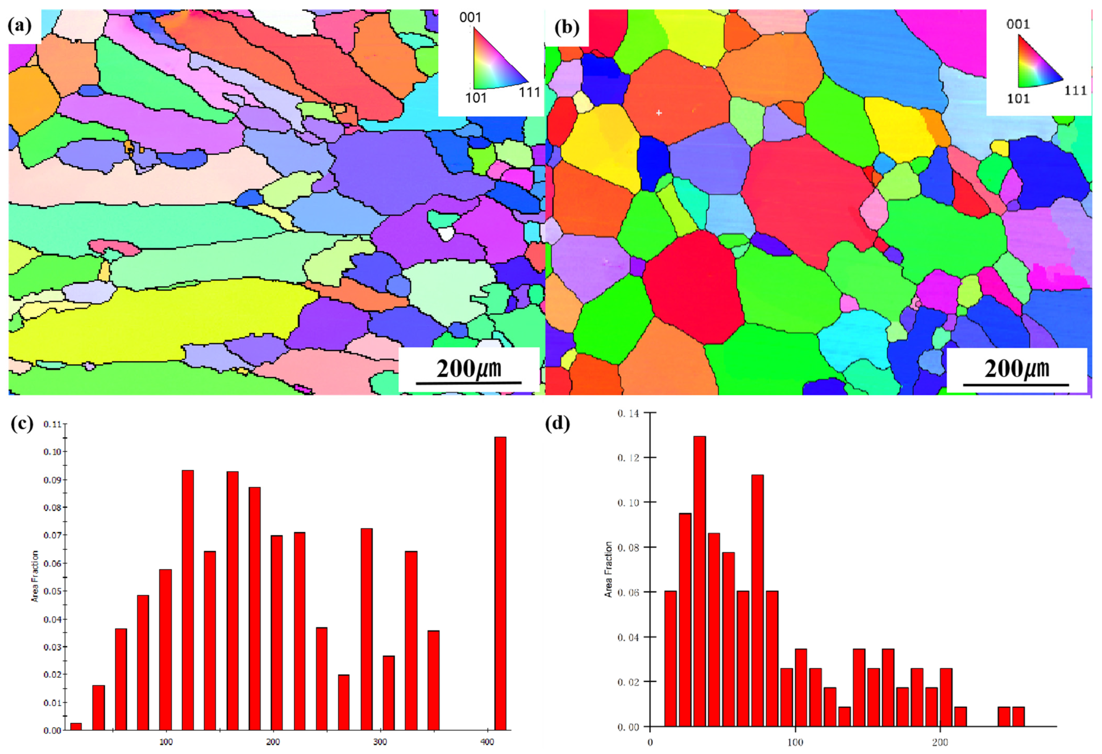
The transformation of grains near the fusion line is very conspicuous, as shown in Figure 8a. Obvious columnar crystal growth was generated under conventional welding. Grain size varies from 20 μm to 400 μm, and most of the grains grow to more than 100 μm in size (see Figure 8c). The largest columnar crystal even reaches 420 μm in size. With ultrasonic assistance, most columnar crystals are transformed into equiaxial crystals, and the grain size is mainly concentrated in the 20–100 μm range, as shown in Figure 8b,d. The maximum grain size is 260 μm, reduced by 180 μm compared with the non-ultrasonic-assisted sample, and the average grain size is reduced from 212.63 μm to 82.1 μm. In addition, columnar grains of the conventional sample have an obvious grain orientation. The main grain orientation is <101>, which is the preferred grain orientation caused by heat flow during the solidification of the weld pool. This is consistent with the morphology observed in the metallographic image. With ultrasonic assistance, most grains are uniformly distributed in the direction of <001>, <101> and <111>. This reflects the fact that the ultrasonic wave can destroy the optimal growth of grains in the weld seam. In addition to the fact that ultrasonic vibration induces more nucleation points during the solidification process of the weld pool metal, its temperature effect also reduces the temperature gradient, which makes the growth trend of grains with a critical nucleation radius equal in each orientation, and finally generates equiaxed grains with a uniform size. It is foreseeable that the significant optimization of the microstructure will inevitably lead to the improvement of mechanical properties, and the effect of grain refinement brought about by ultrasonic vibration is highly desirable.

3.2. Mechanical Properties of Welded Joint under Ultrasonic-Assisted Welding

For the conventional TIG welded joint, the tensile strength is 375 MPa and the elongation is 26.4%, obviously lower than those of the 441 ferritic stainless steel base metal (tensile strength of 384 MPa and elongation of 30.8%). When the elongation rate is up to about 26.4%, the tensile stress reaches the tensile strength of the weld tissue, and a fracture occurs at the position of the weld. After introducing ultrasonic vibration into the welding process, the tensile strength and elongation are improved. Figure 9 shows the stress–strain curves of the welded joints before and after ultrasonic assistance. The specific mechanical property parameters of the welded joints under different ultrasonic powers with a confidence of α = 0.05 are shown in Table 3. As observed, the tensile strength and elongation of the welded joints are different with different ultrasonic powers. They will not increase continuously with the increase in ultrasonic power, but show a trend of first increasing and then decreasing. The highest yield strength, tensile strength and elongation were obtained at 130 W ultrasonic power, improving by 16%, 16% and 20%, respectively, compared with those of the conventional TIG welded joint.
The cross-sectional microhardness measurements of the conventional welded joint and the ultrasonic-assisted welded joint are shown in Figure 10. As can be seen, the hardness of the ultrasonic-assisted sample is higher than that of the conventional sample throughout the welded joint, indicating that ultrasonic-assisted welding can improve the hardness of the whole welded joint. This is the result of grain refinement after the addition of ultrasonic vibration. According to the Hal–Petch formula (δs = δ0 + Kd−1/2, where d is the grain size and δ0 and K are material constants), the hardness is inversely proportional to the decrease in grain size, and the decrease in grain size leads to an increase in hardness, which is consistent with the research results in this paper. The highest hardness of the conventional welded joint is found in the center of the weld seam and gradually decreases towards both sides. The hardness of the heat-affected zone is obviously lower than that of the weld center and fluctuates wildly. In particular, the minimum hardness of the HAZ is lower than that of the base metal. However, although the overall hardness distribution of the ultrasonic-assisted welded joint is similar to that of the conventional welded joint, the hardness of the HAZ is significantly increased under the action of ultrasonic vibration, and is also much higher than that of the base metal. Moreover, the softening phenomena of the HAZ under conventional welding can be effectively solved after introducing ultrasonic vibration into the weld pool. For 441 ferritic stainless steel, HAZ is softened mainly due to the intense growth of coarse columnar grains. Unlike the weld seam, the microstructure of the HAZ does not nucleate and crystallize, and instead only grows under the influence of the welding heat cycle. Hence, it can be seen that the effect of ultrasonic vibration in maintaining the equilibrium temperature field is also prominent except for improving the hardness of the weld seam by increasing the finess of the grains with more nucleation points. This is again illustrated by the small fluctuation in hardness in the HAZ.

3.3. Grain Refinement of Ultrasonic-Assisted Welding

During ultrasonic-assisted TIG welding, ultrasonic vibration is introduced into the weld pool through the base metal and generates alternating sound pressure. When the amplitude of alternating sound pressure is higher than the melt static pressure, a sparse phase (negative-pressure region) and a compressed phase (positive-pressure region) appear in the melt. In the negative-pressure region, the intermolecular binding force is overcome, and the melt is torn to form a cavitation nucleus in the local region. Under the alternating change of the sparse phase and the compressed phase, the cavitation nucleus grows into a cavitation bubble. With the sustained input of alternating sound pressure, the cavitation bubble grows faster and finally collapses after reaching the maximum radius, resulting in a series of cavitation effects. It is known that the amplitude of alternating sound pressure must reach the cavitation threshold to form a cavitation nucleus. This threshold can be expressed as [33,34]:
P a = P 0   P v + 2 3 3 2 σ R 0 3 P 0 P v + 2 σ R 0 1 2
where Pa is the amplitude of alternating sound pressure; P0 is the melt static pressure; Pv is the internal pressure of the cavitation bubble; R0 is the radius of the cavitation nucleus and σ is the surface tension coefficient.
When the cavitation bubble collapses, the high pressure inside the bubble will generate a high-pressure shock wave in the melt in a nearby region to form a micro-jet, causing a high-pressure region around the cavitation bubble. The relationship between the pressure generated during the collapse of the cavitation bubble and the pressure exerted by the cavitation bubble during compression is expressed as [35]:
P m a x = P v P S γ 1 P v γ γ 1
where Pmax is the maximum pressure caused by the collapse of cavitation bubble; PS is the external pressure when the cavitation bubble collapses; and γ is the ratio of specific heat. The ultrasonic cavitation effect in the weld pool increases the maximum pressure of the melt near the cavitation bubble. The variation in melt pressure further changes the solidification and crystallization temperature. According to the Clapeyron equation, the relationship between the solidification and crystallization temperature Tm and the maximum pressure Pmax is expressed as [36]:
d T m d P m a x = T m V L V S L m
where Tm is the solidification and crystallization temperature and Lm is melting heat. It can be concluded that the ultrasonic cavitation effect can increase the theoretical solidification crystallization temperature of the melt by changing the pressure in the local region when the cavitation bubble collapses.
In the solidification and crystallization process of the weld pool, an embryo must reach the critical radius in order to become a stable nucleus. The critical radius is mainly determined by the degree of supercooling. As the degree of supercooling rises, the critical radius decreases, leading to an increase in the nucleation rate. Since the theoretical solidification and crystallization temperature can be raised via the ultrasonic cavitation effect, the degree of supercooling will increase by introducing ultrasonic vibration into the weld pool, resulting in a decrease in the critical radius and an increase in the number of stable nuclei, thus increasing the nucleation rate. In addition, the ultrasonic cavitation effect can reduce the tension at the solid–liquid interface, increase the Gibbs free energy difference between the solid phase and the liquid phase, and reduce the nucleation work. It can also promote the wetting of the second-phase particles like TiN and NbC in the 441 ferritic stainless steel, so as to obtain a higher nucleation rate. Therefore, a large number of stable nuclei can be generated at the original columnar grain position in the weld pool under ultrasonic assistance. With the growth of grains, nuclei come into contact with each other and stop growing, forming a very small equiaxed crystal structure.
With the increase in ultrasonic power, the ultrasonic energy field stimulated in the base metal is enhanced. Yet, owing to the cavitation threshold, the continuous increase in the ultrasonic input power cannot continuously improve the intensity of the ultrasonic cavitation effect. Too large an ultrasonic input power can even weaken the cavitation effect. Thus, the effect of grain refinement and the improvement of mechanical properties will first be enhanced and then weakened with ultrasonic power. As shown from tensile test data, the inflection point of the effective ultrasonic power is 130 W.

4. Conclusions

A special ultrasonic-assisted TIG welding system was developed in this work to improve the coarse columnar grains and poor toughness of the 441 ferritic stainless steel welded joint. Welding experiments were conducted using the self-designed ultrasonic-assisted welding platform, and microstructure observation and mechanical property testing were then carried out to analyze the changes brought about by the addition of ultrasonic vibration. Conclusions are draw as follows:
1. For the conventional welded joint, quiaxed grains are formed only in a very small region in the weld center, and the grain size is quite large, sometimes several times larger than that of the base metal. The remaining area including the heat-affected zone consists of very coarse columnar grains. For the ultrasonic-assisted welded joint, the coarse columnar grains in the welded joint are mostly transformed into very fine equiaxed grains under ultrasonic vibration, especially the coarse columnar grains near the fusion line. Also, the grain orientation becomes random and harmonized compared with the conventional sample.
2. The hardness of the ultrasonic-assisted sample is higher than that of the conventional sample throughout the welded joint due to grain refinement, which is consistent with the Hal–Petch relationship. For the conventional welded joint, the hardness of the heat-affected zone is obviously lower than that of the weld center, and the minimum hardness of the heat-affected zone is even lower than that of the base metal. With ultrasonic assistance, the softening of the heat-affected zone caused by grain coarsening is effectively inhibited, indicating that the effect of ultrasonic vibration in maintaining the equilibrium temperature field is also prominent, except for improving the hardness by increasing the fineness of the grains.
3. The mechanical properties of the welded joint are improved with ultrasonic assistance, but are not improved continuously with the increase in ultrasonic power. They show a trend of first increasing and then decreasing. The highest yield strength, tensile strength and elongation were obtained at 130 W ultrasonic power, improving by 16%, 16% and 20%, respectively, compared with those of the conventional welded joint.

Author Contributions

Conceptualization, X.Z.; Methodology, Y.C.; Validation, W.Z.; Formal analysis, Y.C.; Investigation, Y.L. and Y.Z.; Resources, Y.Z.; Data curation, W.Z.; Writing—original draft, X.Z.; Writing—review and editing, Y.L.; Visualization, Y.L.; Supervision, Y.Z.; Funding acquisition, X.Z. and Y.L. All authors have read and agreed to the published version of the manuscript.

Funding

This work was financially supported by the National Nature Science Foundation of China under Grant No. 52275338 and the Key Scientific and Technological Research and Development Projects of Jilin Provincial Science and Technology Department through Grant No. 20210201056GX.

Data Availability Statement

Data is contained within the article.

Conflicts of Interest

The authors declare no conflict of interest.

References

  1. Zhang, Z.; Han, Y.; Lu, X.; Zhang, T.; Bai, Y.; Ma, Q. Effects of N2 content in shielding gas on microstructure and toughness of cold metal transfer and pulse hybrid welded joint for duplex stainless steel. Mater. Sci. Eng. A 2023, 872, 144936. [Google Scholar] [CrossRef]
  2. Maurya, A.K.; Chhibber, R.; Pandey, C. Heat Input Effect on Dissimilar Super Duplex Stainless Steel (UNS S32750) and Nitronic Steel (N50) Gas Tungsten Arc Weld: Mechanism, Microstructure, and Mechanical Properties. J. Mater. Eng. Perform. 2023, 32, 5283–5316. [Google Scholar] [CrossRef]
  3. Mounarik Das, M.; Ahn, H.; Hong, E.Y.; Kim, S.T.; Han, M.-J.; Pal, H.N.; Kumar, T. Characterization of friction stir welded joint of low nickel austenitic stainless steel and modified ferritic stainless steel. Met. Mater. Int. 2017, 23, 948–957. [Google Scholar]
  4. Okayasu, M.; Shigeoka, T. Effect of Microstructural Characteristics on Mechanical Properties of Ferritic Stainless Steel. J. Mater. Eng. Perform. 2019, 28, 6771–6778. [Google Scholar] [CrossRef]
  5. Dong, Z.; Li, Y.; Lee, B.; Babkin, A.; Chang, Y. Research status of welding technology of ferritic stainless steel. Int. J. Adv. Manuf. Technol. 2020, 118, 2805–2831. [Google Scholar] [CrossRef]
  6. Chen, C.; Shang, C.J.; Weng, J.; Li, D.Y. Corrosion Behavior of a New Developed Ferritic Stainless Steels Used in Automobile Exhaust System. Adv. Mater. Res. 2010, 89–91, 102–106. [Google Scholar] [CrossRef]
  7. Sato, E.; Tanoue, T. Present and future trends of materials for automotive exhaust system. Nippon Steel Tech. Rep. 1995, 64, 13–19. [Google Scholar]
  8. Amuda, M.; Mridha, S. Grain refinement and hardness distribution in cryogenically cooled ferritic stainless steel welds. Mater. Des. 2013, 47, 365–371. [Google Scholar] [CrossRef]
  9. Taban, E.; Kaluc, E.; Dhooge, A. Hybrid (plasma+gas tungsten arc) weldability of modified 12% Cr ferritic stainless steel. Mater. Des. 2009, 30, 4236–4242. [Google Scholar] [CrossRef]
  10. Lakshminarayanan, A.; Balasubramanian, V. An assessment of microstructure, hardness, tensile and impact strength of friction stir welded ferritic stainless steel joints. Mater. Des. 2010, 31, 4592–4600. [Google Scholar] [CrossRef]
  11. Ahn, B.W.; Choi, D.H.; Kim, D.J.; Jung, S.B. Microstructures and properties of friction stir welded 409L stainless steel using a Si3N4 tool. Mater. Sci. Eng. A Struct. Mater. Prop. Microstruct. Process. 2012, 532, 476–479. [Google Scholar] [CrossRef]
  12. Villaret, V.; Deschaux-Beaume, F.; Bordreuil, C.; Fras, G.; Chovet, C.; Petit, B.; Faivre, L. Characterization of Gas Metal Arc Welding welds obtained with new high Cr–Mo ferritic stainless steel filler wires. Mater. Des. 2013, 51, 474–483. [Google Scholar] [CrossRef]
  13. Swati, J.; Nilesh, D.; Rajeev, A. A study on the effect of welding on HAZ, mechanical properties and corrosion of AISI 409m ferritic stainless steel by SMAW, TIG and MIG welding. Int. J. New Innov. Sci. Technol. 2015, 3, 1–9. [Google Scholar]
  14. Sánchez-Cruz, T.d.N.; Curiel-López, F.; López-Morelos, V.; González–Sánchez, J.; Ruiz, A.; Carrillo, E. Optimization of macro and microstructural characteristics of 316L/2205 dissimilar welds obtained by the GMAW-pulsed process. Mater. Today Commun. 2023, 34, 105401. [Google Scholar] [CrossRef]
  15. Mohandas, T.; Reddy, G.M.; Naveed, M. A comparative evaluation of gas tungsten and shielded metal arc welds of a “ferritic” stainless steel. J. Am. Acad. Dermatol. 1999, 94, 133–140. [Google Scholar] [CrossRef]
  16. Wang, Y.; Ding, M.; Zheng, Y.; Liu, S.; Wang, W.; Zhang, Z. Finite-Element Thermal Analysis and Grain Growth Behavior of HAZ on Argon Tungsten-Arc Welding of 443 Stainless Steel. Metals 2016, 6, 77. [Google Scholar] [CrossRef]
  17. Oh, D.; Han, K.; Hong, S.; Lee, C. Effects of alloying elements on the thermal fatigue properties of the 15wt% Cr ferritic stainless steel weld HAZ. Mater. Sci. Eng. A Struct. Mater. Prop. Microstruct. Process. 2012, 555, 44–51. [Google Scholar] [CrossRef]
  18. Lan, H.-X.; Gong, X.-F.; Zhang, S.-F.; Wang, L.; Wang, B.; Nie, L.-P. Ultrasonic vibration assisted tungsten inert gas welding of dissimilar metals 316L and L415. Int. J. Miner. Met. Mater. 2020, 27, 943–953. [Google Scholar] [CrossRef]
  19. Chen, C.; Fan, C.; Liu, Z.; Cai, X.; Lin, S.; Zhuo, Y. Microstructure Evolutions and Properties of Al–Cu Alloy Joint in the Pulsed Power Ultrasonic-Assisted GMAW. Acta Met. Sin. (Engl. Lett.) 2020, 33, 1397–1406. [Google Scholar] [CrossRef]
  20. Li, F.; Chen, F.; Gao, P.; Wang, W.; Yang, C.; Liu, S. Effect of Ultrasonic Power on the Microstructure and Properties of 304 Stainless Steel Welded Joints Through Cold Metal Transfer Welding Assisted with Ultrasonication. Met. Mater. Int. 2023, 29, 3039–3051. [Google Scholar] [CrossRef]
  21. Morisada, Y.; Fujii, H.; Inagaki, F.; Kamai, M. Development of high frequency tungsten inert gas welding method. Mater. Des. 2013, 44, 12–16. [Google Scholar] [CrossRef]
  22. Wang, Y.; Cong, B.; Qi, B.; Yang, M.; Lin, S. Process characteristics and properties of AA2219 aluminum alloy welded by double pulsed VPTIG welding. J. Am. Acad. Dermatol. 2019, 266, 255–263. [Google Scholar] [CrossRef] [PubMed]
  23. Wang, Y.; Qi, B.; Cong, B.; Zhu, M.; Lin, S. Keyhole welding of AA2219 aluminum alloy with double-pulsed variable polarity gas tungsten arc welding. J. Manuf. Process. 2018, 34, 179–186. [Google Scholar] [CrossRef]
  24. Wang, D.; Wu, C.; Suo, Y.; Wang, L.; Liang, Z. Effect of pulse frequency on arc behavior and droplet transfer of 2198 Al-Li alloy by ultra-high-frequency pulse AC CMT welding. J. Mater. Res. Technol. 2019, 8, 3950–3958. [Google Scholar] [CrossRef]
  25. Qi, B.J.; Yang, M.X.; Cong, B.Q.; Liu, F.J. The effect of arc behavior on weld geometry by high-frequency pulse GTAW process with 0Cr18Ni9Ti stainless steel. Int. J. Adv. Manuf. Technol. 2013, 66, 1545–1553. [Google Scholar] [CrossRef]
  26. Wu, K.; Yuan, X.; Li, T.; Wang, H.; Xu, C.; Luo, J. Effect of ultrasonic vibration on TIG welding–brazing joining of aluminum alloy to stee. J. Mater. Process. Technol. 2019, 266, 230–238. [Google Scholar] [CrossRef]
  27. Dai, W.-L. Effects of high-intensity ultrasonic-wave emission on the weldability of aluminum alloy 7075-T6. Mater. Lett. 2003, 57, 2447–2454. [Google Scholar] [CrossRef]
  28. Chen, C.; Fan, C.; Cai, X.; Lin, S.; Yang, C.; Zhuo, Y. Microstructure and mechanical properties of Q235 steel welded joint in pulsed and un-pulsed ultrasonic assisted gas tungsten arc welding. J. Mater. Process. Technol. 2020, 275, 116335. [Google Scholar] [CrossRef]
  29. Sun, Q.J.; Lin, S.B.; Yang, C.L.; Zhao, G.Q. Penetration increase of AISI 304 using ultrasonic assisted tungsten inert gas welding. Sci. Technol. Weld. Join. 2009, 14, 765–767. [Google Scholar] [CrossRef]
  30. Xie, J.; Chen, Y.; Yin, L.; Zhang, T.; Wang, S.; Wang, L. Microstructure and mechanical properties of ultrasonic spot welding TiNi/Ti6Al4V dissimilar materials using pure Al coating. J. Manuf. Process. 2021, 64, 473–480. [Google Scholar] [CrossRef]
  31. Watanabe, T.; Shiroki, M.; Yanagisawa, A.; Sasaki, T. Improvement of mechanical properties of ferritic stainless steel weld metal by ultrasonic vibration. J. Mater. Process. Technol. 2010, 210, 1646–1651. [Google Scholar] [CrossRef]
  32. GB/T 228; Metallic Materials—Tensile Testing. Standardization Administration of China: Beijing, China, 2010.
  33. Jamshidi, R.; Brenner, G. Dissipation of ultrasonic wave propagation in bubbly liquids considering the effect of compressibility to the first order of acoustical Mach number. Ultrasonics 2013, 53, 842–848. [Google Scholar] [CrossRef]
  34. Zhang, Y.N.; Wang, L.; Morioka, S.; Wang, W.M. Modified Lennard-Jones potentials for Cu and Ag based on the dense gaslike model of viscosity for liquid metals. Phys. Rev. B 2007, 75, 014106. [Google Scholar] [CrossRef]
  35. Ma, L.; Shu, G.; Feng, C. Research on Solidification of Metal Melt under Ultrasonic Field. Mater. Sci. Eng. 1995, 13, 2–7. [Google Scholar]
  36. Ashiri, R.; Niroumand, B.; Karimzadeh, F. Physical, Mechanical and dry sliding wear properties of an Al-Si-Mg-Ni-Cu alloy under different processing conditions. J. Alloys Compd. 2014, 582, 213–222. [Google Scholar] [CrossRef]
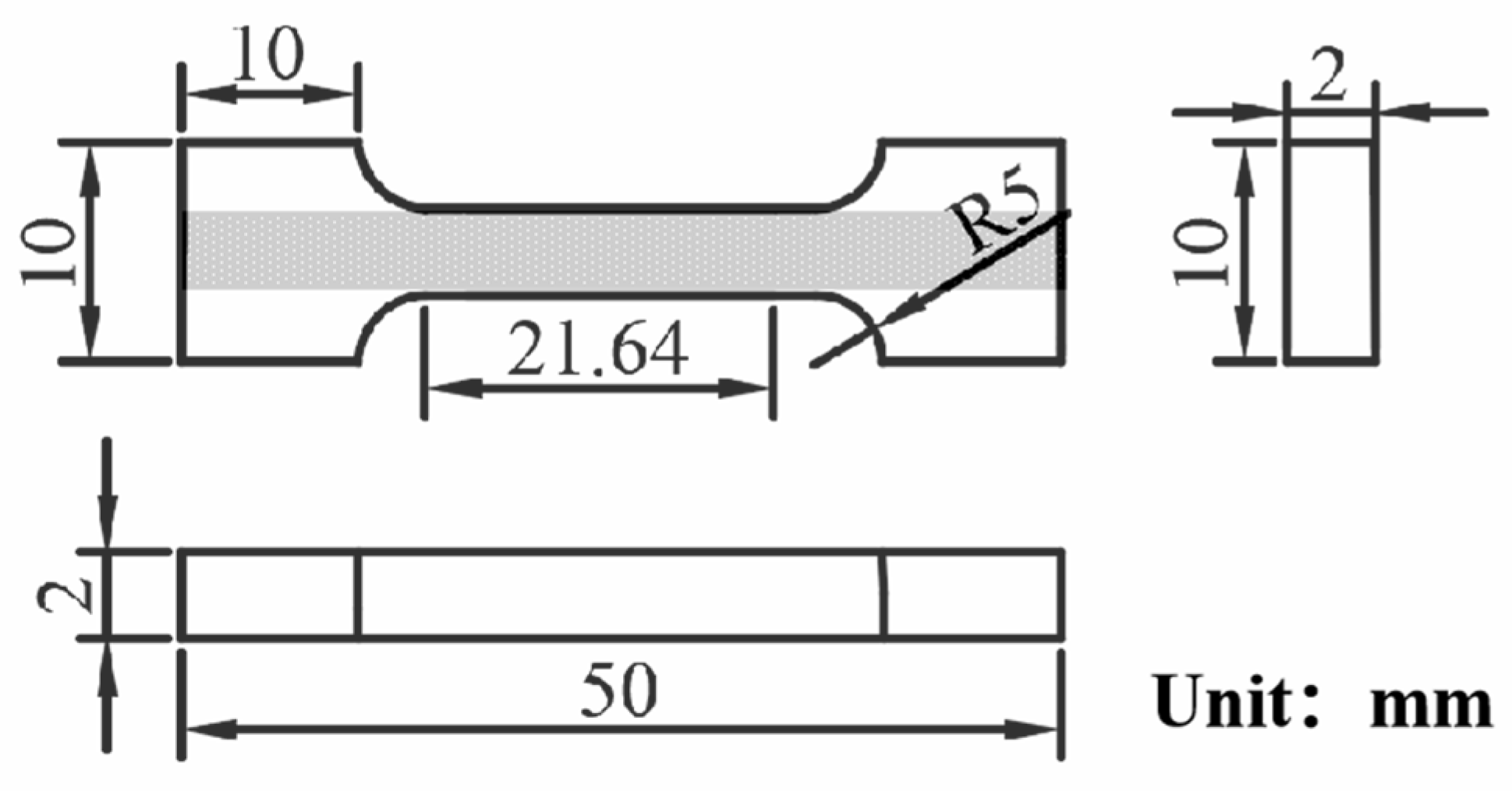
Figure 1. The schematic diagram of tensile sample.
Metals 13 01924 g001
Figure 2. Schematic diagram of the ultrasonic-assisted TIG welding device.
Metals 13 01924 g002
Figure 3. The morphologies of welded joints: (a) macro appearance under 65 A; (b) macro appearance under 70 A; (c) macro appearance under 75 A; (d) macro appearance under 80 A; (e) macro appearance under 85 A; (f) macro appearance under 90 A; (g) microstructure under 80 A; (h) microstructure of weld center; (i) microstructure of heat-affected zone; (j) microstructure of base metal.
Metals 13 01924 g003
Figure 4. The influence of welding current on metallographic structure, melting depth, melting width and their ratio, corresponding to the metallographic image of the (a) 60 A; (b) 65 A; (c) 70 A; (d) 75 A; (e) 80 A sample, respectively; (f) schematic diagram of the weld cross section; (g) relationship between the forming characteristics and welding current.
Metals 13 01924 g004
Figure 5. Comparison of conventional TIG welding and ultrasonic-assisted TIG welding: (a) macro appearance of the weld seam; (b) metallographic image without ultrasonic assistance; (c) metallographic image with ultrasonic assistance.
Metals 13 01924 g005
Figure 6. EBSD results of the whole welded joint: (a) grain distribution of non-ultrasonic-assisted sample; (b) grain distribution of ultrasonic-assisted sample; (c) grain size distribution of non-ultrasonic-assisted sample; (d) grain size distribution of ultrasonic-assisted sample.
Metals 13 01924 g006
Figure 7. EBSD results of the weld center: (a) grain distribution of non-ultrasonic-assisted sample; (b) grain distribution of ultrasonic-assisted sample; (c) grain size distribution of non-ultrasonic-assisted sample; (d) grain size distribution of ultrasonic-assisted sample.
Metals 13 01924 g007
Figure 8. EBSD results of microstructure in the HAZ: (a) grain distribution of non-ultrasonic-assisted sample; (b) grain distribution of ultrasonic-assisted sample; (c) grain size distribution of non-ultrasonic-assisted sample; (d) grain size distribution of ultrasonic-assisted sample.
Metals 13 01924 g008
Figure 9. Tensile test results before and after ultrasonic assistance: (a) stress–strain curves; (b) histogram of tensile strength and elongation.
Metals 13 01924 g009
Figure 10. The microhardness measurements of cross-sectional welded joints under conventional welding and ultrasonic-assisted welding.
Metals 13 01924 g010
Table 1. Chemical composition of 441 ferritic stainless steel (wt.%).
CCrNbTiSiMnPSNi
≤0.0317.5~18.5(3 × wt.%C + 0.3)~1.00.1~0.6≤1.00≤1.00≤0.04≤0.03≤1.00
Table 2. Mechanical properties of 441 ferritic stainless steel.
Yield Strength (MPa)Tensile Strength (MPa)Elongation Rate (%)HV
≥240≥370≥30150
Table 3. Mechanical properties of welded joints.
SampleYield Strength (MPa)Tensile Strength (MPa)Elongation Rate (%)
110 W298 ± 8388 ± 824.6 ± 0.9
130 W332 ± 9436 ± 1031.6 ± 1.2
140 W320 ± 11420 ± 1131.0 ± 0.9
150 W294 ± 8394 ± 1031.4 ± 0.4
No Ultrasonic Input285 ± 10375 ± 1126.4 ± 1.8
Disclaimer/Publisher’s Note: The statements, opinions and data contained in all publications are solely those of the individual author(s) and contributor(s) and not of MDPI and/or the editor(s). MDPI and/or the editor(s) disclaim responsibility for any injury to people or property resulting from any ideas, methods, instructions or products referred to in the content.