Abstract
Fe-based amorphous alloys are considered potential coating materials for applications in marine corrosive environments owing to their high resistance to chloride ion corrosion. Fe-based amorphous alloy (Fe41Co7Cr15Mo14C15B6Y2) was deposited on AISI 1020 steel using ultrasonic-assisted laser cladding. The research findings revealed a gradient structure generated at the junction of the coating and substrate. Ultrasonic promoted crystallization and increased the gradient structure’s average thickness, reducing coating surface cracks. However, ultrasonic had little effect on the amorphous content of the prepared coating surface, which still had a high amorphous content. The Fe-based amorphous coating prepared via laser cladding with ultrasonic demonstrated good corrosion resistance. The corrosion resistance of the coating without ultrasonic was reduced significantly due to cracks. EIS results confirmed that corrosion resistance was related to crystallization and crack issues. Cr element segregation due to crystallization hindered passivation film forming, reducing its corrosion resistance. Crack corrosion enlarged the crack gap and hollowed out the coating and the substrate’s binding zone, accelerating coating failure.
1. Introduction
In the 21st century, humankind has entered a period of large-scale exploitation and utilization of the ocean. Marine development and utilization cannot be separated from advanced marine engineering equipment. Mainstream offshore structures, such as drilling platforms, ocean pastures, offshore wind power, subsea pipelines, and offshore bridges are still steel-made [1,2]. The marine corrosion environment is complex, and almost all corrosion forms, including pitting corrosion, crevice corrosion, stress corrosion, galvanic corrosion, biological corrosion, and erosion, are found in the marine environment [3]. When a steel structure is in service in the marine environment, it is all the time subjected to the erosion of seawater, the marine atmosphere, or sea mud, with corrosion becoming the main failure form of steel-made facilities. Amorphous alloys’ unique “disordered” structures provide them with excellent corrosion resistance [4]. Among them, Fe-based amorphous alloys have the advantages of low cost and abundant resources, providing them with broad industrial applications in marine corrosion protection [5,6]. As early as 1974, it was found that the corrosion resistance of Fe-based amorphous alloy (FeCrPC) to seawater was better than that of traditional austenitic stainless steel, and it still retained low corrosion rates in high Cl− concentration solutions [7]. However, due to critical cooling rates, the size of bulk amorphous materials was limited to tens of millimeters [8], which limited their engineering applications. Thermal spraying, laser cladding, and other metal coating preparation technologies effectively expanded the engineering application of amorphous alloys. Many studies have shown that Fe-based amorphous coatings [9,10,11] have good corrosion resistance, with corrosion current densities of 10−5 and 10−6 A/cm2 in simulated marine environments. Compared with thermal spraying, laser cladding has a low dilution rate, low porosity, and high bonding strength, and is more suitable for preparing amorphous corrosion-resistant coatings.
It is generally believed that there are three main reasons for the high corrosion resistance of Fe-based amorphous alloys: (1) The composition of amorphous alloys is uniform. There is neither microstructure defects nor micro-component segregation, the overall corrosion potential is balanced, and anti-local corrosion ability is strong. (2) The alloy elements that promote the formation of amorphous alloys improve the ability of the alloy to form a solid solution phase and then enhance its passivation ability to resist local corrosion. (3) The activity of surface atoms of amorphous alloys is very high, making the surface rapidly and uniformly passivated. Therefore, only coatings with high amorphous content without cracks have good corrosion resistance, which is also a great challenge for preparing amorphous corrosion-resistant coatings by laser cladding. Current studies have confirmed these aforementioned conclusions. The precipitated crystal phase destroys the composition uniformity of the amorphous coating [12,13,14]. Non-penetrating crack defects cause local chromium deficiency around defects, causing pitting. Penetrating crack defects destroy the integrity of the coating and accelerate regional failure [15]. However, the crystallization and cracking of amorphous coatings by laser cladding are difficult to avoid. Laser cladding amorphous coating is a complex metallurgical process. Alloy element dilution, segregation, and burnout cause coating crystallization and induce microscopic defects such as pores and cracks. Laser cladding is also a typical rapid solidification process, and the solidification process will accumulate residual stress. When room temperature brittleness of the coating is high, the coating cracks easily and forms penetrating cracks. Heat input has vital roles in preparing amorphous coatings by laser cladding. With increasing heat input, the tendency for coating crystallization increases, but this is conducive to reducing the residual stress of the coating and inhibiting cracks. When reducing heat input, the results are the opposite. In other words, in preparing amorphous coatings by laser cladding, “crystallization inhibition” and “crack inhibition” are inconsistent or contradictory. Researchers have proposed many methods to increase the content of the amorphous phase [16,17] or reduce coating cracks [18,19,20]; however, few studies have reported that a single process can simultaneously achieve “crystallization inhibition” and “crack inhibition”. Ultrasonic-assisted manufacturing has been successfully applied to casting and extended to welding and cladding [21,22,23]. Ultrasonic effects, such as cavitation, sound flow, and resonance generated by ultrasonic propagation in the molten pool have been shown to regulate element distribution, phase formation, and microstructure evolution during solidification. Inspired by these works, in the present study, Fe-based amorphous coatings were deposited on AISI 1020 steel via laser cladding assisted by ultrasonic. The microstructure and corrosion resistance qualities of the Fe-based amorphous coating were studied, and corrosion mechanisms in seawater addressed.
2. Experimental Procedure
2.1. Coating Preparation
An AISI 1020 steel plate with dimensions of 200 mm × 100 mm × 10 mm was selected as a substrate, polished with sandpaper, and cleaned with alcohol before laser cladding. Fe-based amorphous alloy powder with a nominal composition of Fe41Co7Cr15Mo14C15B6Y2 (at %) was selected as the raw material for depositing coating, which had good glass-forming ability (GFA) with a critical cooling rate of 6.5 K/s. A self-developed ultrasonic-assisted laser cladding system (Figure 1) was used to fabricate Fe-based amorphous coatings on AISI 1020 steel, which consisted of a 6 kW semiconductor laser, a 1 kW ultrasonic generator, and a powder feeder. An ultrasonic horn directly contacted the bottom of the substrate, and ultrasound was transmitted into the molten pool through the substrate. Laser deposition was carried out as per the parameters listed in Table 1. Nitrogen (99.99%) and argon (99.995%) were used as feeding and shielding gas during deposition.
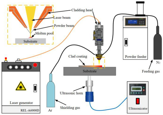
Figure 1.
Schematic diagram of the ultrasonic-assisted laser cladding system.

Table 1.
Ultrasonic-assisted laser cladding parameters.
2.2. Microstructure Examinations
Amorphous and crystalline phases formed in the laser-clad Fe-based amorphous coating were characterized using an X-ray diffractometer (XRD, Rigku, D/max-2500 PC, Tokyo, Japan) in the standard 2θ geometry, from 20° to 90° with a 0.02° step. The cross-section microstructure of the coating was observed by a scanning electron microscope (SEM, Tescan, MIRA3, Brno, Czech Republic). Before the test, cross-sections of the clad sample were polished and etched using aqua regia and then washed in alcohol. High-magnification electronic images and selected area electron diffraction (SAED) patterns were acquired using a transmission electron microscope (TEM, Thermo Fisher, FEI Talos F200X, Wilmington, DC, USA). Before the test, the clad coating was cut into a 3 mm (diameter) × 1 mm (thickness) sample using a wire electrical discharge machining (WEDM), ground to a thickness of about 0.3 mm with metallographic sandpaper, and then reduced to 0.03 mm by ion-beam thinning.
2.3. Corrosion Tests
A tri-electrode configuration (Metrohm, PGSTAT302N, Herisau, Switzerland) for electrochemical measurements was adopted using an electrochemical workstation, including a Fe-based amorphous coating working electrode, a Pt counter electrode, and a saturated gangue reference electrode. To simulate a marine corrosion environment, a 3.5wt. % NaCl solution was selected as the electrolyte in corrosion tests. The potentio-dynamic curve, measured from −750 mVSCE to −150 mVSCE with a scanning rate of 0.5 mV/s, was used to characterize the corrosion current and corrosion potential of the Fe-based amorphous coating. Before the test, the coating was immersed in open-circuit potential conditions for 5400 s to ensure an electrochemically stable state. The corrosion process of the Fe-based amorphous coating was simulated using electrochemical impedance spectroscopy (EIS). The input signal was sinusoidal, with an amplitude of 10 mv and a frequency range of 100 kHz–10 mHz.
3. Results and Discussion
3.1. Microstructural Examination Results
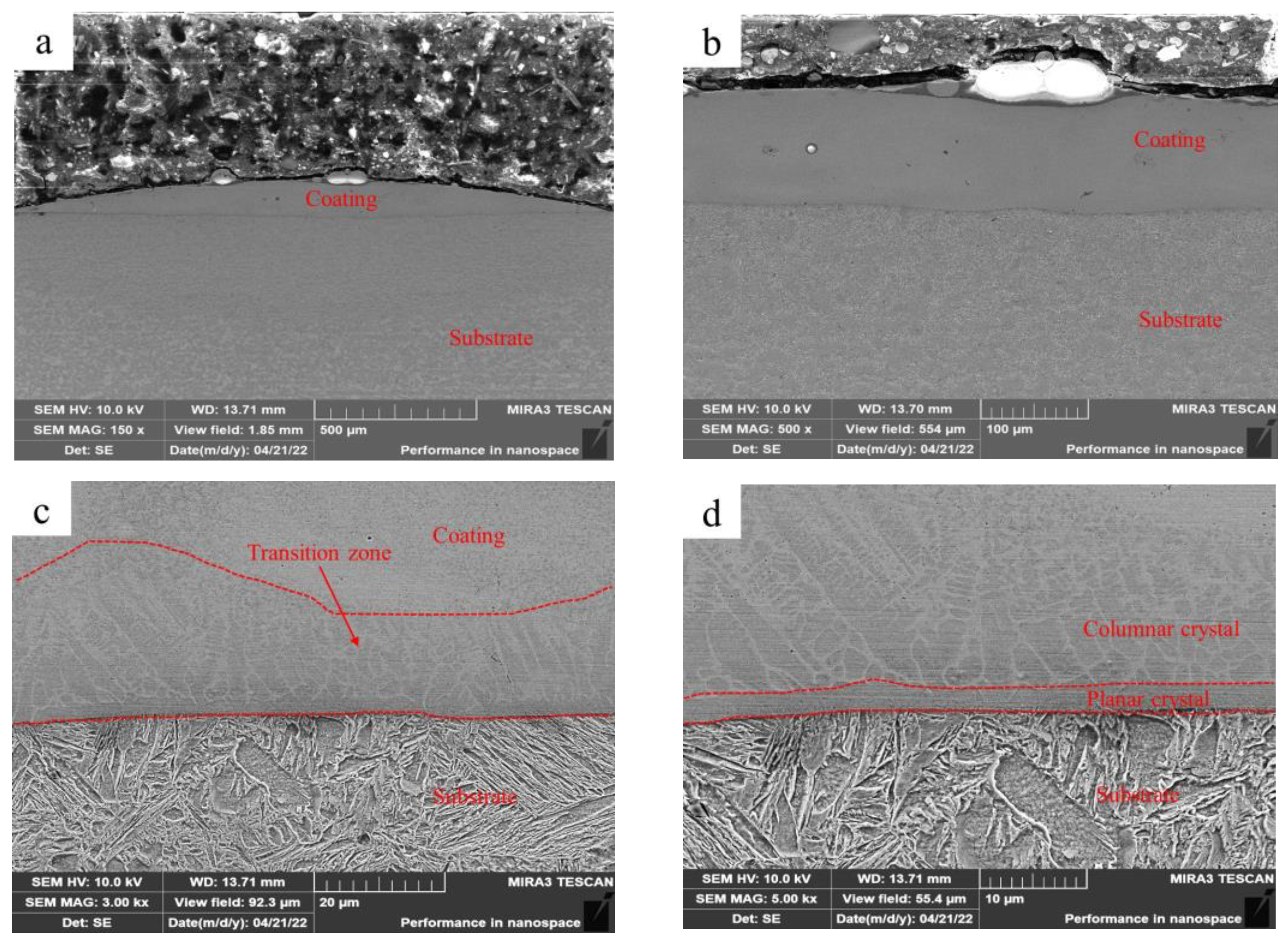
Figure 2 shows the microstructure of the Fe-based amorphous coating (U0) fabricated using laser cladding without ultrasonic. As shown in Figure 2a, the single-pass Fe-based amorphous layer (U0) is flat, with an average thickness of 150 μm and an average width of 1800 μm. There are a few longitudinal cracks in the coating, some of which are through cracks (Figure 2b). Further observations (Figure 2c) reveal a thin transition zone at the bottom of the coating. The transition zone shows more detailed microstructures after zooming in 5000 times, as shown in Figure 2d. We observed that the transition zone is a gradient structure, which is composed of planar crystals, columnar crystals, and equiaxed crystals. Previous studies also observed similar results [24,25].
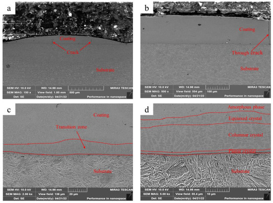
Figure 2.
Microstructure of the Fe-based amorphous coating (U0) fabricated using laser cladding without ultrasonic: (a) ×150; (b) ×500; (c) ×2000; and (d) ×5000.
Figure 3 shows the microstructure of Fe-based amorphous coating (U1000) fabricated via laser cladding with ultrasonic. As shown in Figure 3a, the single-pass laser-clad layer becomes flatter when used with ultrasonic. The average thickness of the coating decreases to 140 μm while the width increases to 1850 μm. We observed that the average thickness of the transition zone also increases (Figure 3c). After further magnification (Figure 3d), we confirmed that ultrasonic promotes the growth of columnar and equiaxed crystals in the transition zone, which become coarser. The in situ generated micro-gradient structure reduces differences in mechanical properties, such as hardness, elastic modulus, and plasticity between the amorphous coating and the substrate, effectively improving the toughness and bonding strength of the coating, and reducing cracks [26].

Figure 3.
Microstructure of the Fe-based amorphous coating (U1000) fabricated using laser cladding with ultrasonic: (a) ×150; (b) ×500; (c) ×3000; and (d) ×5000.
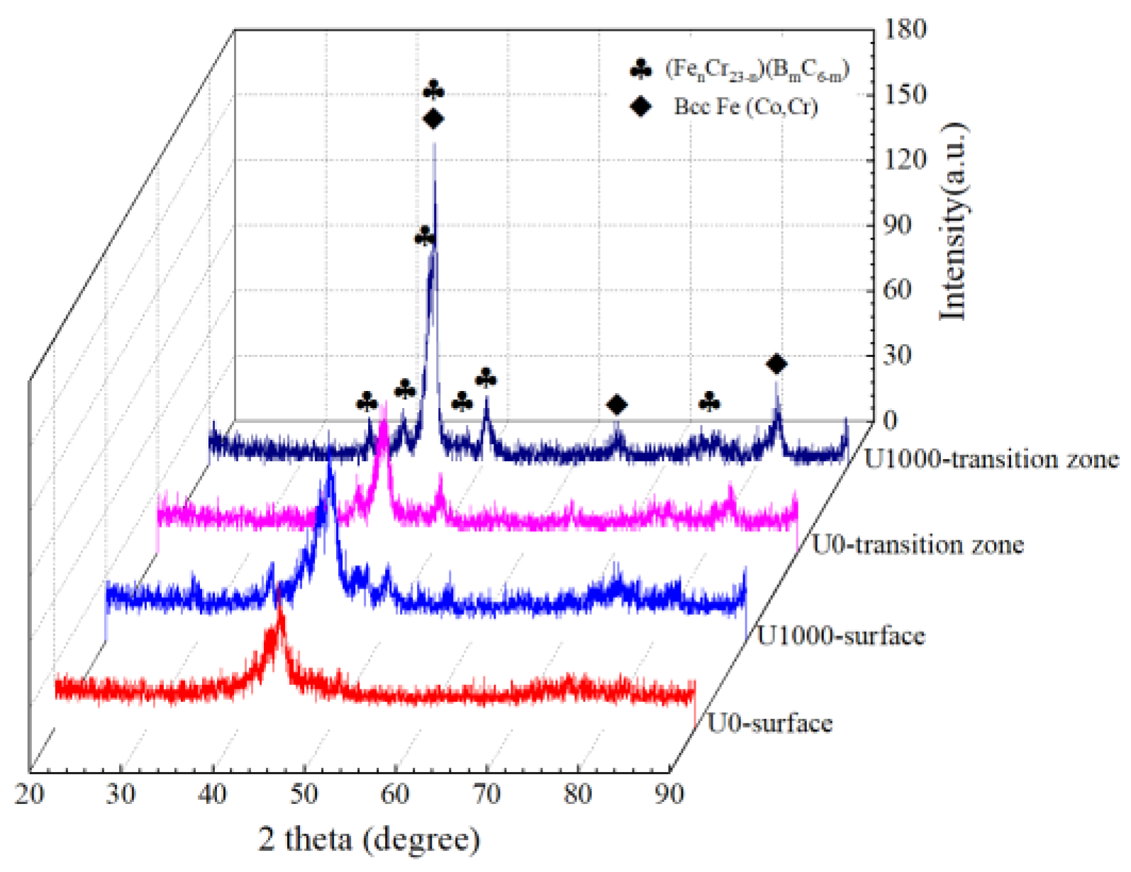
Figure 4 shows XRD patterns of Fe-based amorphous coatings fabricated using laser cladding, with and without ultrasonic. The detection location includes the coating surface, and a crystallization transition zone which is 120 μm from the coating surface. As shown in Figure 4, whether or not assisted with ultrasonic, laser-clad Fe-based amorphous coatings undergo crystallization, and crystalline phases precipitated are Bcc-Fe (Co, Cr) and (FenCr23−n) (BmC6−m). XRD patterns of the two coating surfaces are almost identical, with a broad halo in the 2θ geometry of 40–50°, indicating a highly non-crystalline nature [27]. Compared with the coatings’ surfaces, crystal peaks in the transition zone become sharp and significantly intense, especially for coating U1000. This result corresponds to the microstructure of the coating.

Figure 4.
XRD patterns of Fe-based amorphous coatings.
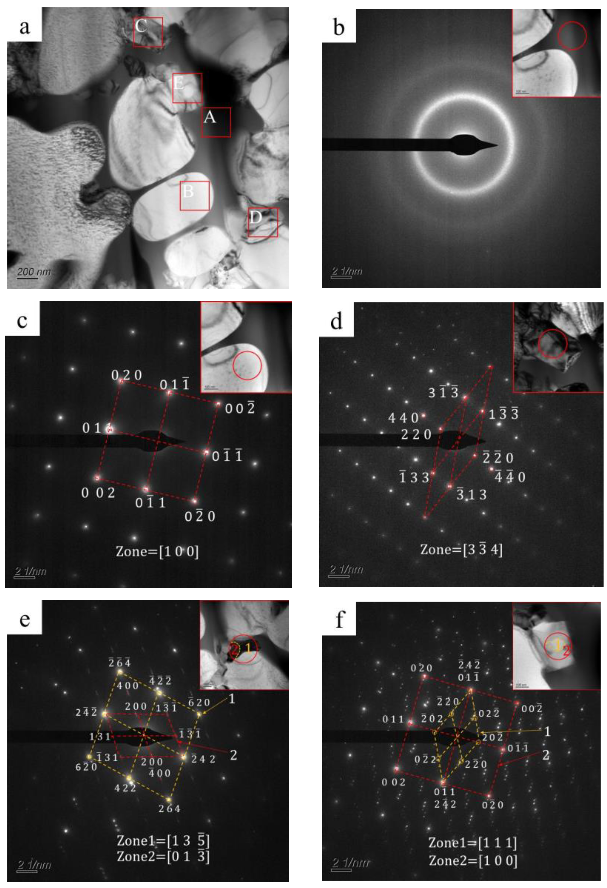
Transmission electron microscopy (TEM) was used to confirm the crystallization phase. Figure 5 shows a bright-field TEM image and corresponding selected area electron diffraction (SAED) patterns of the typical region in the transition zone. As shown, three different regions are observed in the bright-field TEM image: a black phase (A region in Figure 5a), a white phase (B region in Figure 5a), and gray phases (C, D, and E regions in Figure 5a). The white phase has smooth edges, while gray phases have irregular shapes. The black phase fills in the phases as mentioned above. As shown in Figure 5b, the SAED pattern of the black phase is composed of a central diffuse scattering spot and surrounding diffuse rings, which are typical featured of an amorphous phase. The SAED pattern of the white phase (Figure 5c) indicates a body-centered cubic structure with an axis of [1 0 0]. The spacings between (0 1 1) and (0 0 2) crystal faces are 0.203 nm and 0.143 nm, corresponding to the bcc-Fe (Co, Cr) in XRD patterns, as shown in Figure 4. Figure 5d shows the SAED pattern of the gray phase (C region in Figure 5a), indicating a face-centered cubic structure, and its crystal axis is [3 4]. Wherein the crystal face spacing of (1 3) is about 0.244 nm, which agrees well with (FenCr23−n) (BmC6−m). As shown in Figure 5e, the SAED pattern of the gray phase (D region in Figure 5a) is a nesting of two sets of patterns [28], which are consistent with (FenCr23−n) (BmC6−m) patterns. As shown in Figure 5f, the SAED pattern of the gray phase (E region in Figure 5a) is also a nesting of two sets of diffraction patterns. One is consistent with the (FenCr23−n) (BmC6−m) pattern with an axis of [1 1 1]; the other one agrees well with the bcc-Fe (Co, Cr) pattern, with an axis of [1 0 0].
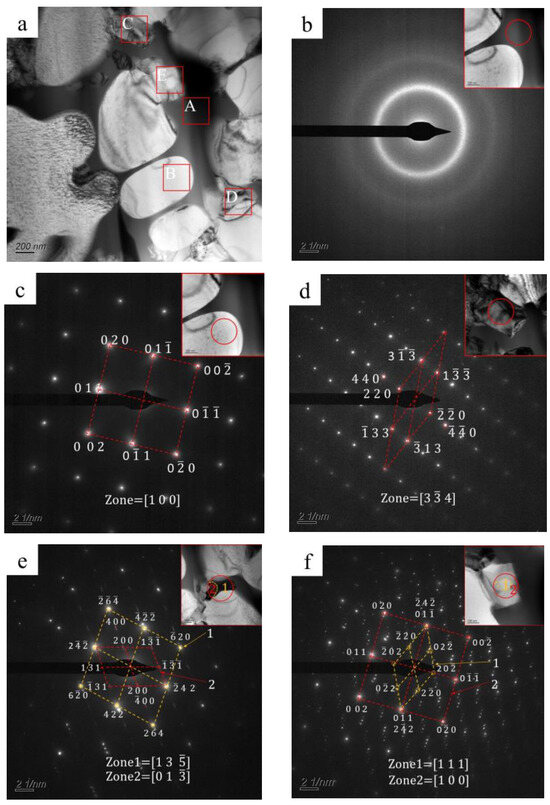
Figure 5.
(a) Bright-field TEM image (A: black phase, B: white phase, C–E: gray phases) and (b–f) corresponding selected area electron diffraction (SAED) patterns for typical regions.
3.2. Corrosion Test Results
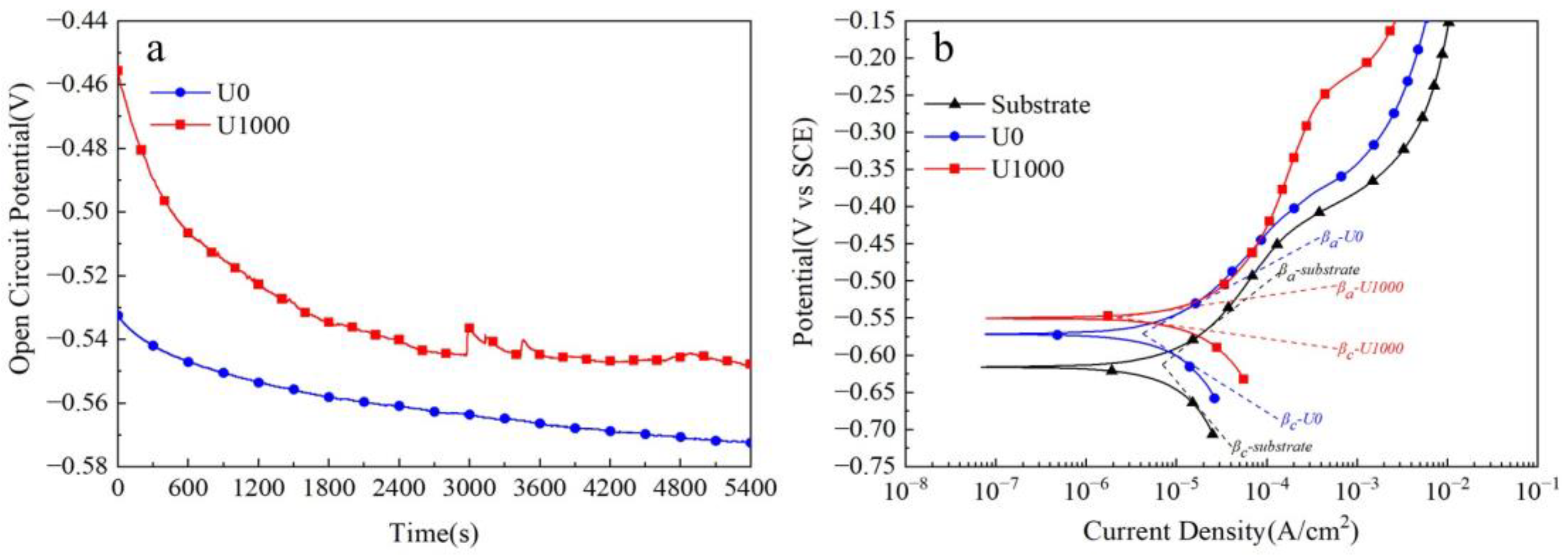
Figure 6 shows corrosion test results for Fe-based amorphous alloy coatings in 3.5 wt.% NaCl solution. As seen in Figure 6a, the open-circuit potential (VOCP) of the Fe-based amorphous coating (U0) presents a decreasing trend. It decreases from about −0.53 VSCE to about −0.57 VSCE, and is unstable until 5400 s. By contrast, the open-circuit potential (VOCP) of the coating (U1000) shows a decreasing trend first and then stabilization. It drops from about −0.45 VSCE to about −0.55 VSCE and remains stable after about 3600 s of immersion. Interestingly, we observed that the open-circuit potential curve (VOCP) of the coating (U1000) has some steep peaks at 700 s, 1500 s, 3000 s, and 3500 s, which is a passivation phenomenon. The open-circuit potential (VOCP) is closely related to the crystallization of the coating. At the beginning of the test, the coating’s (U1000) potential decreases rapidly due to potential differences between crystalline and amorphous phases. After about 3000 s, an electrochemical balance between amorphous and crystalline phases is reached, and the open-circuit potential tends to be stable and no longer decreases. The transient potential peak indicates that the coating is passivated during immersion. Still, the passivation film formed in the early stage is unstable, easily destroyed, and cannot create a steady potential. Until 3000 s, the open-circuit potential (VOCP) of the coating (U1000) tends to be stable. Cracks are other critical factors affecting coatings’ open circuit potential (VOCP). With increasing soaking time, the solution gradually penetrates the cracks and contacts the substrate, causing electrochemical reactions and forming crack corrosion. Therefore, the open-circuit potential (VOCP) of the coating (U0) continues to decrease and cannot be stabilized.
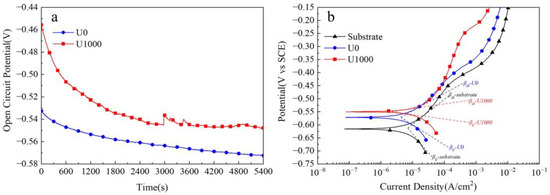
Figure 6.
Corrosion tests of Fe-based amorphous alloy coatings in 3.5 wt.% NaCl solution: (a) open-circuit potential curves; (b) potentio-dynamic polarization curves.
Figure 6b shows the potentio-dynamic polarization curves of Fe-based amorphous coatings in 3.5 wt.% NaCl soluti wt.%on. As demonstrated, with increasing polarization potential, the current density of both coatings increases, indicating slight anode corrosion. The substrate’s current density suddenly increases when the polarization potential reaches −0.45 VSCE, suggesting it enters an active dissolution stage. The coating (U0) exhibits almost the same changes as the substrate; when the polarization potential reaches −0.45 VSCE, the current density suddenly increases. However, for the coating (U1000), when the polarization potential exceeds −0.45 VSCE, the current density rises slowly until −0.25 VSCE. The corresponding corrosion parameters from potentio-dynamic polarization curves are listed in Table 2. Polarization resistances (Rp) were calculated using the Stern–Geary [29,30,31] equation (1). The comparison shows that the corrosion resistance of the coating (U1000) is better than that of the coating (U0). The polarization resistance of coating U1000 is twice that of coating U0, and the corrosion rate of the former is only one-third of the latter.
where βa and βc are the slopes of the anodic and cathodic Tafel polarization curves.
Table 2.
Potentio-dynamic polarization curve parameters of Fe-based amorphous alloy coatings and substrate in 3.5 wt.% NaCl solution.
A previous study showed that the bulk Fe-based amorphous alloy (Fe41Co7Cr15Mo14C15B6Y2) with the same chemical composition as the coating had better corrosion resistance, whose self-corrosion potential and self-corrosion current density were −0.33 VSCE and 1.55 × 10⁻⁶ A/cm2 [32], respectively. There are two reasons for the excellent corrosion resistance of bulk Fe-based amorphous alloys. Firstly, bulk Fe-based amorphous alloy is a single-phase material without defects, such as grain boundary, dislocation, inclusion, and second phase, etc. [33]. Secondly, the Cr element in bulk Fe-based amorphous alloy is distributed evenly due to the absence of a crystallization phase [34,35,36]. In a 3.5 wt.% NaCl solution, the Fe element dissolves preferentially, and the Cr element is rapidly oxidized to form a passive film resistant to chloride ion erosion [37,38]. An appropriate amount of Mo element can improve corrosion resistance [39]. Although the Fe-based amorphous coating has the same nominal chemical composition as the bulk Fe-based amorphous alloy, crystallization is unavoidable during laser cladding, which results in the formation of crystalline phases such as BCC-Fe (Co, Cr) and (FenCr23−n) (BmC6−m). (FenCr23−n) (BmC6−m) facilitates Cr element segregation, significantly hindering passivation film forming. Amorphous and crystal phases are different in terms of potential; a galvanic reaction occurs between the two phases in the corrosive solution, meaning the passivation film has difficulties existing in a stable manner. Therefore, although the coating is passivated during dynamic potential polarization tests, the passivation potential range is narrow. The passivation film dissolves when the polarization potential reaches −0.25 VSCE. There are many cracks in the Fe-based amorphous coating (U0). These cracks mostly penetrate from the coating surface to the substrate. With increasing time, the corrosive solution gradually penetrates these coating cracks; it contacts the substrate so that a galvanic cell is formed, significantly expanding the corrosion current density of the electrode system.
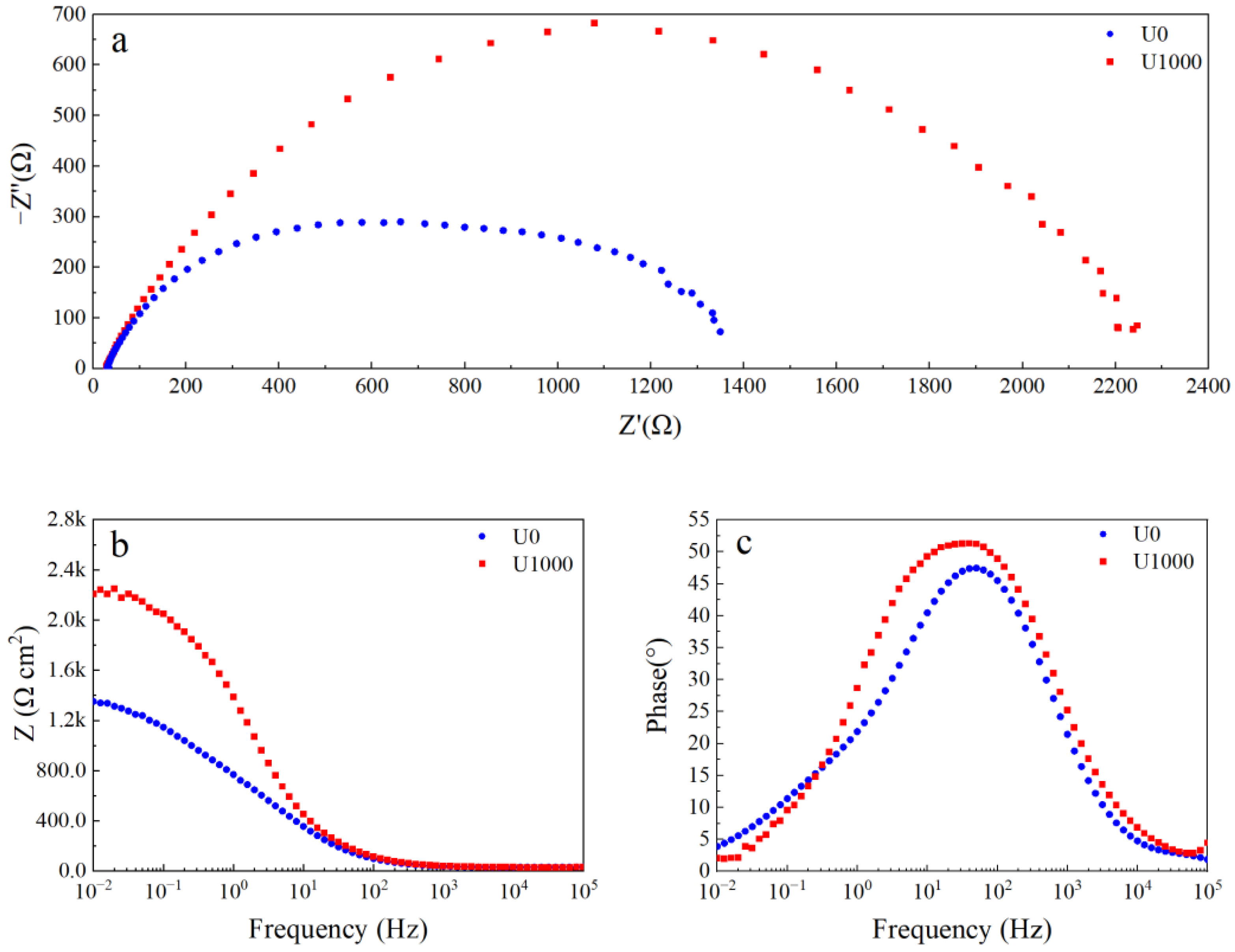
Electrochemical impedance spectroscopy (EIS) is used to describe the corrosion behavior of Fe-based amorphous coatings after 48 h of immersion in a 3.5 wt.% NaCl solution. As shown in Figure 7a, two capacitive arcs in the Nyquist plot of the coating (U1000) are associated with two time constants. The first time constant at the high-frequency range represents the electrochemical response of the coating; the second time constant at the low-frequency range represents the charge transfer process and the double-layer charge-discharge process. The impedance modulus of the coating (U1000) at the low-frequency range is about 2.2 kΩ (Figure 7b). As shown in Figure 7c, the phase angle of the coating (U1000) at the medium-frequency range is above 45° which is below 45° at low- and high-frequency ranges, indicating that slight local corrosion occurs in the coating. The Nyquist plot of the coating (U0) still shows a semicircle (Figure 7a). However, compared with the coating (U1000), the semicircle is flatter, corresponding to another time constant at the middle-frequency range, which may be the electrochemical response of the coating crack. The impedance modulus of the coating (U0) at the low-frequency range reduces to 1.4 kΩ. The phase angle peak of the coating at the middle-frequency range becomes narrow, and the highest phase angle reduces to less than 45°, which indicates that the coating (U0) has undergone severe corrosion.
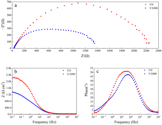
Figure 7.
EIS curve of Fe-based amorphous alloy coatings after 48 h of immersion in 3.5 wt.% NaCl solution: (a) Nyquist plot; (b) Bode impedance magnitude plot; and (c) Bode phase angle plot.
To generate quantitative information from EIS results and confirm the time constant presented in Figure 7, electrochemical impedance spectroscopy is modeled with electrical equivalent circuits (EECs). As discussed earlier, the two Fe-based amorphous coatings (U0 and U1000) are composite coatings composed of amorphous and crystalline phases, and the coating (U0) prepared without ultrasonic has dense reticular cracks. The coating’s capacitance response is a dispersion capacitance rather than an ideal capacitance. Therefore, a constant–phase–element (CPE) is used to fit acquired experimental data instead of the capacitance element, which is good for describing characteristics such as surface and/or normal heterogeneities [40,41,42].
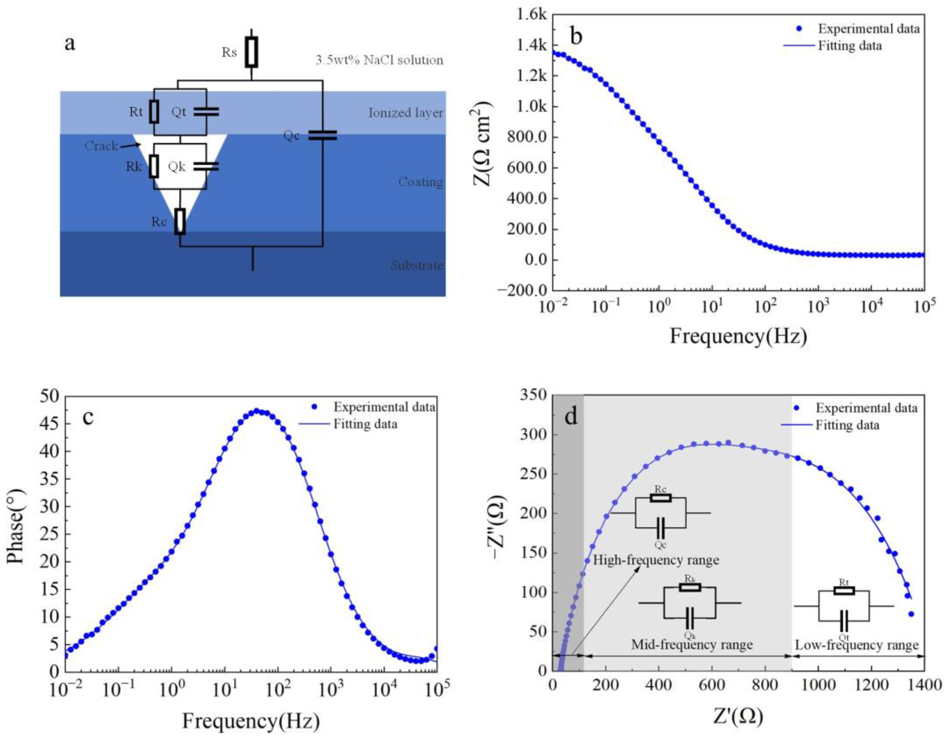
Figure 8 shows electrochemical impedance spectroscopy (EIS) fitting results for the Fe-based amorphous coating (U1000). As shown in Figure 8a, in the equivalent circuit model, Rs represents the resistance of the 3.5 wt.% NaCl solution; Rc and Qc are the resistance and capacitance of the coating (U1000), respectively; Rt and Qt are in parallel, corresponding to the charge transfer resistance between the amorphous phase and the crystal phase, and the double-layer capacitance, respectively. The equivalent circuit model accurately describes the structural characteristics of the crack-free amorphous composite coating corrosion cell. As seen from Figure 8b–d, the two-time-constant equivalent circuit models of the coating (U1000) are highly consistent with experimental data (χ2 = 0.0205). The time constant of the high-frequency range is the electrochemical response of the coating, while the low-frequency range is the charge transfer process and double layer charging and discharging process. Table 3 shows electrochemical impedance spectroscopy (EIS) fitting parameters for the Fe-based amorphous coating (U1000). The resistance of the Fe-based amorphous coating (U1000) is 587 Ω·cm2; the charge transfer resistance is 1650 Ω·cm2. The Fe-based amorphous coating (U1000) has good corrosion resistance, which is higher than ordinary steel but far lower than the bulk amorphous alloy with the same chemical composition.
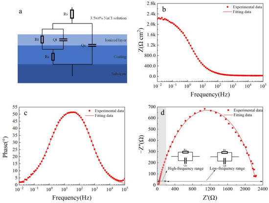
Figure 8.
The fitted results of the EIS curve for the Fe-based amorphous coating (U1000) after 48 h of immersion in 3.5 wt.% NaCl solution: (a) equivalent circuit models; (b) Bode impedance magnitude plot; (c) Bode phase angle plot; and (d) Nyquist plot.
Table 3.
Fitted parameters of the EIS curve for the Fe-based amorphous coating (U1000).
Figure 9 shows electrochemical impedance spectroscopy (EIS) fitting results for the Fe-based amorphous coating (U0). As shown in Figure 9a, compared with the coating (U1000), two more components, Rk and Qk, are proposed in the equivalent circuit model, representing charge transfer resistance and double-layer capacitance formed in the coating crack. The physical model of the equivalent circuit accurately characterizes the structural characteristics of the corrosion cell for the cracked amorphous composite coating. As seen from Figure 9b–d, the three-time-constant equivalent circuit model of the coating (U0) fits the experimental data well (χ2 = 0.017). Among the three time constants, except for the coating capacitor in the high-frequency range and the double-layer capacitor in the low-frequency range, there is a less prominent time constant in the mid-frequency range. This time constant is caused by solution penetration into the coating crack, as shown in Figure 9a. Table 4 shows the fitting parameters of each component of the equivalent circuit for the Fe-based amorphous coating (U0). As seen from Table 4, the resistance of the Fe-based amorphous coating (U0) is only 87 Ω·cm2, much lower than the crack-free coating (U1000). Coating resistance is closely related to density. When the corrosion solution penetrates coating cracks and contacts the substrate, the corrosion system is changed fundamentally. Compared with the coating (U1000) prepared by ultrasonic-assisted laser cladding, the charge transfer resistance of the coating (U0) reduces to 632 Ω·cm2. The charge transfer resistance is inversely proportional to the corrosion rate, confirming that coating cracks accelerate corrosion.

Figure 9.
The fitted results results of the EIS curve for the Fe-based amorphous coating (U0) after 48 h of immersion in a 3.5 wt.% NaCl solution: (a) equivalent circuit models; (b) Bode impedance magnitude plot; (c) Bode phase angle plot; and (d) Nyquist plot.
Table 4.
Fitted parameters of the EIS curve for the Fe-based amorphous coating (U0).
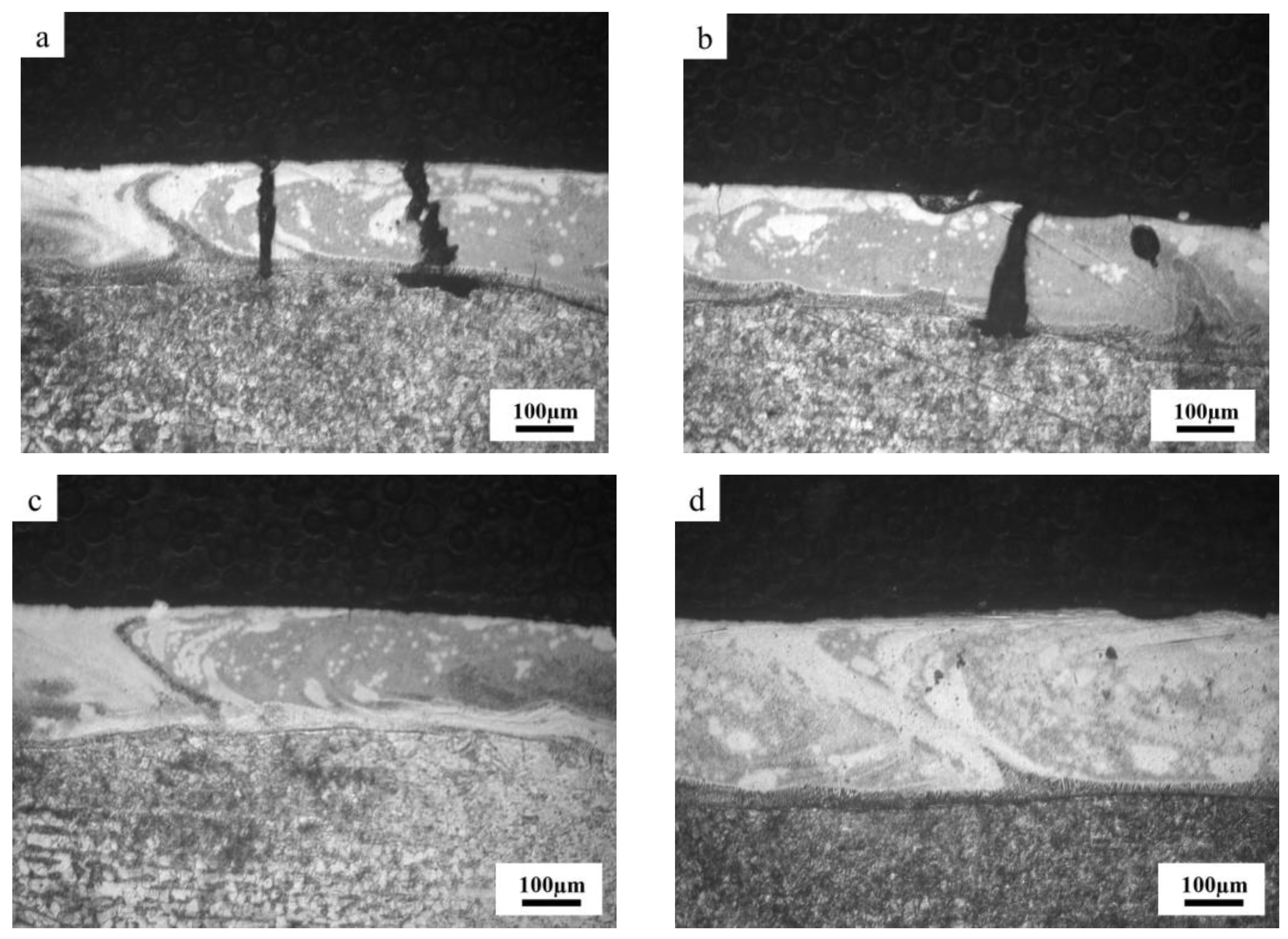
To further clarify the relationship between coating cracks and corrosion behavior, Fe-based amorphous coatings (U0 and U1000) prepared by laser cladding with and without ultrasonic were immersed in 3.5 wt.% NaCl solution for 48 h. Figure 10 shows a cross-sectional image of Fe-based amorphous coatings (U0 and U1000) after immersion corrosion. As shown in Figure 10a,b, coating cracks becomes wide and present as an inverted wedge shapes. In other words, crack gaps near the surface of the coating are smaller than those near the substrate. We observed that severe substrate corrosion simultaneously extends along the interface between the coating and the substrate. The main reason for the aforementioned corrosion phenomenon in the crack area is that the Fe-based amorphous coating prepared by laser cladding is a composite coating with a gradual transition from crystal to amorphous on the coating surface. With increasing distance from the substrate, the amorphous phase content gradually increases. The surface of the coating with a high amorphous phase content has a high potential, while the potential of the complete crystalline substrate is the lowest. Therefore, crack corrosion from the coating surface to the substrate is gradually intensified, and the substrate has the highest corrosion rate. This crack corrosion hollows out the coating and substrate binding zone, accelerating coating failure.

Figure 10.
Cross-section morphology of Fe-based amorphous coatings after corrosion: (a,b) U0; (c,d) U1000.
4. Conclusions
Fe-based amorphous coatings (Fe41Co7Cr15Mo14C15B6Y2) were deposited on an AISI 1020 substrate using laser cladding assisted with ultrasonic. The microstructure and corrosion resistance of the Fe-based amorphous coatings were studied in this work. The study then focused on the corrosion behavior of the coatings using AC impedance spectroscopy in a simulated marine environment.
- (1)
- Fe-based amorphous coatings (U0 and U1000) are composites composed of amorphous phases and crystal phases, including (FenCr23−n) (BmC6−m) and bcc-Fe (Cr, Co). Ultrasonic promotes crystallization of the coating (U1000) but has little effect on the amorphous content of the coating surface.
- (2)
- There are gradient structures at the junction of the coatings (U0 and U1000) and substrates, composed of a planar crystal layer, columnar crystal layer, and equiaxed crystal layer. Ultrasonic increases the average thickness of the gradient structure, thereby reducing surface cracks on the coating (U1000).
- (3)
- The Fe-based amorphous coating (U1000) prepared using laser cladding with ultrasonic shows better corrosion resistance than the Fe-based amorphous coating (U0) fabricated without ultrasonic, but much lower than the bulk amorphous material with the same chemical composition.
- (4)
- The crystallization products of the coatings (U0 and U1000), including (FenCr23−n) (BmC6−m), cause Cr element segregation in the coating (U0 and U1000), significantly hindering passivation film forming. Electrochemical reactions between amorphous and crystal phases accelerate the passive film’s dissolution.
- (5)
- After immersion corrosion of the coating (U1000), cracks become wide. This presents inverted wedge shapes with narrow tops and wide bottoms, which are related to the potential gradient caused by an increase of the amorphous phase from the bottom to the surface of the coating. Crack corrosion hollows out the coating and substrate binding zone, accelerating coating failure.
Author Contributions
Conceptualization, H.H. and M.X.; methodology, Q.W.; validation, M.X.; formal analysis, Q.W.; investigation, H.H.; resources, M.X.; data curation, Q.W.; writing—original draft preparation, H.H.; writing—review and editing, M.X.; supervision, M.X. All authors have read and agreed to the published version of the manuscript.
Funding
This research is funded by Major scientific and technological innovation projects in Shandong Province (2023CXGC010407), and Major special projects in Yantai City (2023ZDCX018).
Data Availability Statement
The data presented in this study are available on request from the corresponding author. The data are not publicly available due to privacy.
Acknowledgments
This work was supported by Yantai Economic and Technological Development Zone Management Committee. The original powder was supplied by Chen Qingjun from Nanchang Hangkong University.
Conflicts of Interest
The authors declare no conflict of interest.
References
- Mohamed, A.E. Offshore Structures, 2nd ed.; Gulf Professional Publishing: Houston, TX, USA, 2012; pp. 383–443. [Google Scholar]
- Subrata, K.C. Handbook of Offshore Engineering; Elsevier Science: Amsterdam, The Netherlands, 2005; pp. 1127–1143. [Google Scholar]
- Campbell, S.A.; Campbell, N.; Walsh, F.C. Developments in Marine Corrosion; Woodhead Publishing: Sawston, UK, 1998. [Google Scholar]
- Li, H.X.; Lu, Z.C.; Wang, S.L.; Wu, Y.; Lu, Z.P. Fe-based bulk metallic glasses: Glass formation, fabrication, properties and applications. Prog. Mater. Sci. 2019, 103, 235–318. [Google Scholar] [CrossRef]
- Souza, C.A.C.; Ribeiro, D.V.; Kiminami, C.S. Corrosion resistance of Fe-Cr-based amorphous alloys: An overview. J. Non-Cryst. Solids 2016, 442, 56–66. [Google Scholar] [CrossRef]
- Wang, H.Z.; Cheng, Y.H.; Yang, J.Y.; Wang, Q.Q. Influence of laser remelting on organization, mechanical properties and corrosion resistance of Fe-based amorphous composite coating. Surf. Coat. Technol. 2021, 414, 127081. [Google Scholar] [CrossRef]
- Hashimoto, K. 2002 WR Whitney Award Lecture: In Pursuit of New Corrosion-Resistant Alloys. Corrosion 2002, 58, 715–722. [Google Scholar] [CrossRef]
- Lou, H.B.; Wang, X.D.; Xu, F.; Ding, S.Q.; Cao, Q.P.; Hono, K.; Jiang, J.Z. 73 mm-diameter bulk metallic glass rod by copper mould casting. Appl. Phys. Lett. 2011, 99, 051910. [Google Scholar] [CrossRef]
- Zhang, C.; Guo, R.Q.; Yang, Y.; Wu, Y.; Liu, L. Influence of the size of spraying powders on the microstructure and corrosion resistance of Fe-based amorphous coating. Electrochim. Acta 2011, 56, 6380–6388. [Google Scholar] [CrossRef]
- Zhou, Z.; Wang, L.; Wang, F.C.; Zhang, H.F.; Liu, Y.B.; Xu, S.H. Formation and corrosion behavior of Fe-based amorphous metallic coatings by HVOF thermal spraying. Surf. Coat. Technol. 2009, 204, 563–570. [Google Scholar] [CrossRef]
- Koga, G.Y.; Wolf, W.; Schulz, R.; Savoie, S.; Bolfarini, C.; Kiminami, C.S.; Botta, W.J. Corrosion and wear properties of FeCrMnCoSi HVOF coatings. Surf. Coat. Technol. 2019, 357, 993–1003. [Google Scholar] [CrossRef]
- Marzo, F.F.; Pierna, A.R.; Vega, M.M. Effect of irreversible structural relaxation on the electrochemical behavior of Fe78−xSi13B9Cr(x=3,4,7) amorphous alloys. J. Non-Cryst. Solids 2003, 329, 108–114. [Google Scholar] [CrossRef]
- Berger, J.E.; Jorge, A.; Koga, G.Y.; Roche, V.; Kiminami, C.S.; Bolfarini, C.; Botta, W.J. Influence of chromium concentration and partial crystallization on the corrosion resistance of FeCrNiB amorphous alloys. Mater. Charact. 2021, 179, 111369. [Google Scholar] [CrossRef]
- Gan, Z.; Zhang, C.; Zhang, Z.R.; Chen, Z.J.; Liu, L. Crystallization-dependent transition of corrosion resistance of an Fe-based bulk metallic glass under hydrostatic pressures. Corros. Sci. 2021, 179, 109098. [Google Scholar] [CrossRef]
- Lin, T.J.; Sheu, H.H.; Lee, C.Y.; Lee, H.B. The study of mechanical properties and corrosion behavior of the Fe-based amorphous alloy coatings using high velocity oxygen fuel spraying. J. Alloys Compd. 2021, 867, 159132. [Google Scholar] [CrossRef]
- Wang, S.L.; Zhang, Z.Y.; Gong, Y.B.; Nie, G.M. Microstructures and corrosion resistance of Fe-based amorphous/nanocrystalline coating fabricated by laser cladding. J. Alloys Compd. 2017, 728, 1116–1123. [Google Scholar] [CrossRef]
- Gargarella, P.; Almeida, A.; Vilar, R.; Afonso, C.R.M.; Peripolli, S.; Rios, C.T.; Bolfarini, C.; Botta, W.J.; Kiminami, C.S. Formation of Fe-based glassy matrix composite coatings by laser processing. Surf. Coat. Technol. 2014, 240, 336–343. [Google Scholar] [CrossRef]
- Lu, Y.Z.; Huang, G.K.; Wang, Y.Z.; Li, H.G.; Qin, Z.X.; Lu, X. Crack-free Fe-based amorphous coating synthesized by laser cladding. Mater. Lett. 2018, 210, 46–50. [Google Scholar] [CrossRef]
- Cui, Y.; Shen, J.Q.; Geng, K.P.; Hu, S.S. Fabrication of FeCoCrNiMnAl0.5-FeCoCrNiMnAl gradient HEA coating by laser cladding technique. Surf. Coat. Technol. 2021, 412, 127077. [Google Scholar] [CrossRef]
- Guo, S.F.; Liu, L.; Li, N.; Li, Y. Fe-based bulk metallic glass matrix composite with large plasticity. Scr. Mater. 2010, 62, 329–332. [Google Scholar] [CrossRef]
- Zhao, Y.L.; Zhang, W.W.; Meng, F.S.; Wang, Z.; Zhang, D.T.; Yang, C. Microstructure and Mechanical Properties of as-Cast Al-5.0Cu-0.6Mn-0.6Fe Alloy Produced by Ultrasonic Vibration and Applied Pressure. Rare Met. Mater. Eng. 2018, 47, 457–462. [Google Scholar]
- Zhu, S.H.; Wang, N.Q.; Li, S.; Huang, G.; Ge, S.; Du, P.H.; Zhang, L.; Sun, Y.F.; Guan, S.K. Study on the materials flow, microstructure and mechanical properties of ultrasonic vibration-assisted friction stir weld of 1500 MPa martensitic steel. Mater. Charact. 2023, 206, 113409. [Google Scholar] [CrossRef]
- Mohsan, A.U.H.; Zhang, M.N.; Wang, D.F.; Zhao, S.; Wang, Y.S.; Chen, C.Y.; Zhang, J.H. State-of-the-art review on the Ultrasonic Vibration Assisted Laser Cladding (UVALC). J. Manuf. Process. 2023, 107, 422–446. [Google Scholar] [CrossRef]
- Wang, H.Z.; Cheng, Y.H.; Yang, J.Y.; Liang, X.B. Microstructure and properties of Fe based amorphous coatings deposited by laser cladding under different preheating temperatures. J. Non-Cryst. Solids 2023, 602, 122081. [Google Scholar] [CrossRef]
- Zhu, Y.Y.; Li, Z.G.; Li, R.F.; Li, M.; Feng, K.; Wu, Y.X.; Wada, T.; Kato, H. High power diode laser cladding of Fe–Co–B–Si–C–Nb amorphous coating: Layered microstructure and properties. Surf. Coat. Technol. 2013, 235, 699–705. [Google Scholar] [CrossRef]
- Xiao, M.Y.; Jiang, F.C.; Guo, C.H.; Song, H.L.; Dong, T. Investigation on microstructure and mechanical properties of Fe-based amorphous coatings prepared via laser cladding assisted with ultrasonic vibration. Opt. Laser. Technol. 2023, 262, 109294. [Google Scholar] [CrossRef]
- Zeng, X.R.; Hu, Q.; Fu, M.W.; Xie, S.H. Investigation of the free volume change of Fe41Co7Cr15Mo14C15B6Y2 bulk metallic glass using the cyclic thermal dilatation test. J. Non-Cryst. Solids 2012, 358, 2682–2686. [Google Scholar] [CrossRef]
- Nespolo, M. Unravelling the diffraction pattern of a twin. I. Fundamentals. Z. Krist-Cryst. Mater. 2016, 231, 553–560. [Google Scholar] [CrossRef]
- Milanti, A.; Matikainen, V.; Koivuluoto, H.; Bolelli, G.; Lusvarghi, L.; Vuoristo, P. Effect of spraying parameters on the microstructural and corrosion properties of HVAF-sprayed Fe–Cr–Ni–B–C coatings. Surf. Coat. Technol. 2015, 277, 81–90. [Google Scholar] [CrossRef]
- Lin, C.H.; Duh, J.G. Corrosion behavior of (Ti–Al–Cr–Si–V)xNy coatings on mild steels derived from RF magnetron sputtering. Surf. Coat. Technol. 2008, 203, 558–561. [Google Scholar] [CrossRef]
- Chou, W.J.; Yu, G.P.; Huang, J.H. Corrosion behavior of TiN-coated 304 stainless steel. Corros. Sci. 2001, 43, 2023–2035. [Google Scholar] [CrossRef]
- Wang, L.; Chao, Y.S. Corrosion behavior of Fe41Co7Cr15Mo14C15B6Y2 bulk metallic glass in NaCl solution. Mater. Lett. 2012, 69, 76–78. [Google Scholar] [CrossRef]
- Suryanarayana, C.; Inoue, A. Bulk Metallic Glasses, 1st ed.; CRC Press: Boca Ratton, FL, USA, 2011. [Google Scholar]
- Yang, Y.; Zhang, C.; Peng, Y.; Yu, Y.; Liu, L. Effects of crystallization on the corrosion resistance of Fe-based amorphous coatings. Corros. Sci. 2012, 59, 10–19. [Google Scholar] [CrossRef]
- Duarte, M.J.; Kostka, A.; Jimenez, J.A.; Choi, P.; Klemm, J.; Crespo, D.; Raabe, D.; Renner, F.U. Crystallization, phase evolution and corrosion of Fe-based metallic glasses: An atomic-scale structural and chemical characterization study. Acta Mater. 2014, 71, 20–30. [Google Scholar] [CrossRef]
- Li, H.X.; Yi, S. Corrosion behaviors of bulk metallic glasses Fe66.7C7.0Si3.3B5.5P8.7Cr2.3Al2.0Mo4.5 having different crystal volume fractions. Mater. Chem. Phys. 2008, 112, 305–309. [Google Scholar] [CrossRef]
- Tan, M.W.; Akiyama, E.; Habazaki, H.; Kawashima, A.; Asami, K.; Hashimoto, K. The role of chromium and molybdenum in passivation of amorphous Fe-Cr-Mo-P-C alloys in deaerated 1 M HCl. Corros. Sci. 1996, 38, 2137–2151. [Google Scholar] [CrossRef]
- Pang, S.; Zhang, T.; Asami, K.; Inoue, A. Formation of bulk glassy Fe75–x–yCrxMoyC15B10 alloys and their corrosion behavior. J. Mater. Res. 2011, 17, 701–704. [Google Scholar] [CrossRef]
- Wang, Y.; Jiang, S.L.; Zheng, Y.G.; Ke, W.; Sun, W.H.; Wang, J.Q. Effect of molybdenum, manganese and tungsten contents on the corrosion behavior and hardness of iron-based metallic glasses. Mater. Corros. 2014, 65, 733–741. [Google Scholar] [CrossRef]
- Hirschorn, B.; Orazem, M.E.; Tribollet, B.; Vivier, V.; Frateur, I.; Musiani, M. Determination of effective capacitance and film thickness from constant-phase-element parameters. Electrochim. Acta 2010, 55, 6218–6227. [Google Scholar] [CrossRef]
- Lukács, Z. The numerical evaluation of the distortion of EIS data due to the distribution of parameters. Electroanal. Chem. 1997, 432, 79–83. [Google Scholar] [CrossRef]
- Lukács, Z. Evaluation of model and dispersion parameters and their effects on the formation of constant-phase elements in equivalent circuits. Electroanal Chem. 1999, 464, 68–75. [Google Scholar] [CrossRef]


Disclaimer/Publisher’s Note: The statements, opinions and data contained in all publications are solely those of the individual author(s) and contributor(s) and not of MDPI and/or the editor(s). MDPI and/or the editor(s) disclaim responsibility for any injury to people or property resulting from any ideas, methods, instructions or products referred to in the content. |
© 2023 by the authors. Licensee MDPI, Basel, Switzerland. This article is an open access article distributed under the terms and conditions of the Creative Commons Attribution (CC BY) license (https://creativecommons.org/licenses/by/4.0/).