Article

Determination of the Effect of Heat Input during Laser Welding on the Magnitude of Residual Stresses in the Refurbishment of Al Alloy Casting

1
Department of Technology, Materials and Computer Aided Production, Faculty of Mechanical Engineering, Technical University of Košice, 042 00 Košice, Slovakia
2
Department of Automotive Production, Faculty of Mechanical Engineering, Technical University of Košice, 042 00 Košice, Slovakia
3
Department of Applied Mechanics and Mechanical Engineering, Faculty of Mechanical Engineering, Technical University of Košice, 042 00 Košice, Slovakia
4
Department of Industrial Automation and Mechatronics, Faculty of Mechanical Engineering, Technical University of Košice, 042 00 Košice, Slovakia
5
Institute of Materials Research, Slovak Academy of Sciences, Watsonova 47, 040 01 Košice, Slovakia
*
Author to whom correspondence should be addressed.
Metals 2023, 13(12), 2003; https://doi.org/10.3390/met13122003
Submission received: 13 November 2023 / Revised: 6 December 2023 / Accepted: 9 December 2023 / Published: 13 December 2023
(This article belongs to the Special Issue Renovation of Parts to Save Metals (Volume 2))

Abstract

:
The paper presents the results of research on the evaluation of the quality of coating layers made by a laser. The base material, which was Dievar steel (1.2343), was coated with a single layer using additional materials in the form of a wire with a diameter of ø 1.0 mm. As additional material, wires with chemistry corresponding to steels 1.2343 and 1.6356 were used. The primary objective was to verify the possibilities of innovative use of additive materials based on maraging steels, which were chosen from the production of two manufacturers with slightly different chemical compositions. The experiment verified the influence of the cladding parameters on the residual stress values around the fabricated maraging layers. Metallographic analysis by light microscopy was carried out in order to identify the individual structures as well as to assess the occurrence of internal defects in the coatings. The effect of the mixing of the coating metal with the base material was also assessed by means of a low-load hardness assessment, which was carried out in accordance with EN ISO 4063-2. Based on the results, it can be concluded that, in terms of residual stresses, the measured values were approximately the same for all the additive materials used; however, due to the desired mechanical properties of the additively formed layers, it is possible to recommend additive materials based on medium- and high-alloy steels for additive manufacturing.

1. Introduction

The restoration of functional component surfaces and their rapid integration into the production process is a hot topic. Currently, a wide range of technologies based on arc heat processes, energy-beam processes, or special combined so-called hybrid methods can be applied for the restoration of components. In addition to surface restoration, the additive manufacturing of tailor-made structural units is currently highly topical. The issue of the formation of functional layers is the target of much research, the results of which are applied in various branches of mechanical engineering and the metallurgical industry. In the study [1], the authors Muigai et al. addressed the issue of repairing stainless steel components using GTAW technology in order to optimize the welding parameters and thus minimize the impact of the repair technology on the degradation of the corrosion properties of the materials being joined as well as preserving its tribological properties. The problem of surface restoration creating functional layers resistant to harsh tribological conditions has been addressed in the studies by Ashokkumar et al. [2] who implemented coating-formation processes by a cold spray process (CSP) using a thermal spray technology in which a coating (10–40 μm) is formed in the solid state by the impingement of powder particles with supersonic velocity (200–1200 m.s−2) on a coupon employing a compressed gas jet below the melting point of the coating powder. The chosen CSP parameters with the used additive material allowed for the creation of high-quality coating layers. Vinas et al. [3] carried out an investigation into the possibility of applying surfacing using PTA technology by employing a plasma beam, whereby the quality of the surfacing was satisfactory and there was minimal thermal effect on the substrate surface. A similar effect occurred in the subsurface areas presented in the studies conducted by [4,5] who applied progressive laser control minimizing the heat input in the fabrication of the overlays. The effect of alloying additives on the resulting chemical composition of the coatings was evaluated in the works of [6] Trembach et al., where the aim of modifying the chemical composition of the fluxes was to increase the tribological resistance of the coatings. Also, in the work [7] by Vinas et al., the research was focused on the application of new types of additive materials for submerged arc-welding processes in the restoration of functional surfaces of continuous-casting steel rolls. The research demonstrated the possibilities of restoring these extremely stressed components in metallurgical primary production.
By appropriately selecting renewal of functional areas, it is possible to minimize the costs of new parts, minimize downtime in production, reduce the necessity to produce new parts and minimize energy inputs for their production, allowing for the reduction of the amount of used raw materials, materials, and semifinished products and, thus, contribute in no small measure to the reduction of the burden on the environment [8,9,10,11]. The economic aspect is extremely important in the context of constantly increasing prices of raw materials and skilled labour. Therefore, the restoration of functional areas of components by arc or energy-beam additive methods is becoming extremely interesting and desirable. The restoration of functional surfaces of components made on the basis of steels, as well as nonferrous alloys, requires the implementation of knowledge from the field of material behaviour during and after metallurgical processes, which is closely related to the formation of residual stresses due to the influence of heat input, within the framework of innovative solutions [12,13,14,15].
Another important factor is also the setting of appropriate process parameters of thermal modes prior to the actual process of formation of functional layers, such as preheating, during the selected methods, procedures, and strategies for the formation of individual layers, and in no small part plays an important role in the subsequent heat-treatment process of the renovated components [16,17,18,19]. The heat-treatment processes are mainly focused on the reduction of internal stresses, after cladding processes, or after the machining and finishing of surfaces. Heat-treatment processes are also used in order to obtain the required hardnesses of functional surfaces, which in no small measure influence the resulting properties of the layers resisting the combined tribodegradation factors [20,21,22,23,24,25,26,27]. Conventional methods of inspecting these layers, which include visual inspection of the surfaces and capillary inspection, are applied to assess the quality of the newly formed layers. These inspections make it possible to detect defects occurring on the surface of the newly formed surfaces. Surface defects and subsurface defects can be detected in magnetic materials by magnetic inspection methods and also by eddy-current inspection. Internal defects can be identified by ultrasound. The reflection method is preferred when applying various angular probes. To no small extent, radiation-based inspection methods are also applied as part of nondestructive inspection. These presented methods allow the identification of defects in the layer and also in the sublayer regions. A very important factor limiting the service life of functional surfaces or refurbished units, in addition to defects identifiable by nondestructive testing (NDT), is residual stresses. The processes of manufacturing and refurbishment of functional surfaces are mainly based on metallurgical processes, and the levels of residual stresses are significantly influenced by the type of coating technology used [28,29,30,31,32,33,34,35]. For the evaluation of residual tensions around welds and clads, not only nondestructive (such as X-ray) but also semidestructive assessment methods are currently used [36,37,38,39]. Residual tensions are a frequent initiator of cracks in load-bearing structures, which is prevented in many research studies [40,41,42,43,44,45,46,47]. At present, numeric simulations are also used for the determination of residual stress [48,49,50]. Researchers aim to set up simulation parameters so that it is as accurate as possible to restrict experimentally determined values [51,52,53,54,55,56]. In the case of numerical simulation of the welding processes, there is a problem defining marginal conditions so that they are condemned with real conditions not only the welding process but also the attachment of the base material, etc.
The paper presents the results of research in the field of evaluation of the quality of renovation layers applied on the functional surfaces of unheated injection moulds for the production of aluminium castings. The functional surfaces of the injection moulds are manufactured from medium-alloy steel grades. The research on the influence of the surfacing parameters on the properties of the newly formed layers was focused on the analysis of the quality of the cladding caterpillars when using three types of additive materials. Cladding wires with a diameter of ø 1.0 mm were used, the material composition of which corresponded to steel grades 1.2343 and 1.6356. The influence of the cladding process on the values of residual stresses in the vicinity of the clads was evaluated in the experiments. The quality of the clads was evaluated on cross-sectional metallographic sections by light microscopy, where the influence of the cladding parameters on the structure of the clads, as well as the changes in the heat-affected area of the subcoat layers, was monitored. The low-load hardness, according to Vickers, was also evaluated in the investigated areas. The influence of the heat-affected regions on the residual stress levels is documented by the drilling method carried out at two different locations at the same distance from the abutment axis. Although the implementation of the clads was automated, the microstructure results show some differences in the subsurface layers.
In addition to the conventional methods for evaluating the quality of the overlayers, the paper presents the results of an original investigation of residual stress measurement by the drilling method. The distribution of residual stresses in the vicinity of the weld to a depth of 1 mm was determined. Standard-use nondestructive X-ray methods provide information about residual stresses in the subsurface layers.

2. Materials and Methods

In order to repair and renovate the mould parts of moulds for high-pressure casting of aluminium alloys, samples of experimental clads were prepared on the base material of grade 1.2343 (Dievar) with dimensions of 150 × 130 × 30 mm, which was refined to a hardness value of 44–48 HRC. Cladding parameters of analysed samples are in Table 1. The chemical composition of the steel mat. No. 1.2343 detected by the chemical spectrometer Belec Compact Port (BAS Rudice, Rudice, Czech Republic) is in Table 2. The mechanical properties given by the manufacturer are declared in Table 3. This is a medium-alloy steel intended for the production of forming tools and moulds for casting processes. In practice, conventional arc-cladding processes are often applied for the formation of functional layers and the restoration of surfaces, mainly because of the low cost of the equipment. However, these arc processes are characterised by high heat input to the fusion bath as well as to the submerged areas, where undesirable metallurgical changes and the formation of undesirable hard structures such as martensite often occur in medium- and high-alloy steels. It is therefore necessary to implement the production of layers using technologies that minimise the heat input to the materials. Technologies such as CMT (Cold Metal Transfer), MAGPulse (metal active gas) and, to no small extent, laser-cladding processes are increasingly being used. These processes are well robotisable.
The deposition strategies of individual caterpillars are programmable, while in the formation of layers using the laser, it is also possible to apply additive materials in the form of powders, which significantly affects the possibilities of modifying the chemical composition of the formed layers.
In the presented experiment, the production of the coating layers was realized by means of a TruDisk 4002 solid-state disk laser with BEO D70 focusing optics (Trumpf, Ditzingen, Germany). Three types of additive materials were used. Since the process was reimplemented on a robotic workstation, the additive materials used were in the form of wires with a diameter of ø 1.0 mm. Three wires were used, and these were based on the base material of the mould mat. No. 1.2343 (Dievar), with additive material No. 1.6356 (UTPA 702) and additive material mat. No. 1.6356 (Dratec). The chemical compositions of the various additive materials are shown in Table 4.
Cladding parameters were selected on the basis of previously performed experiments on a given type of solid-state laser.
The following experiments were analyzed:
-
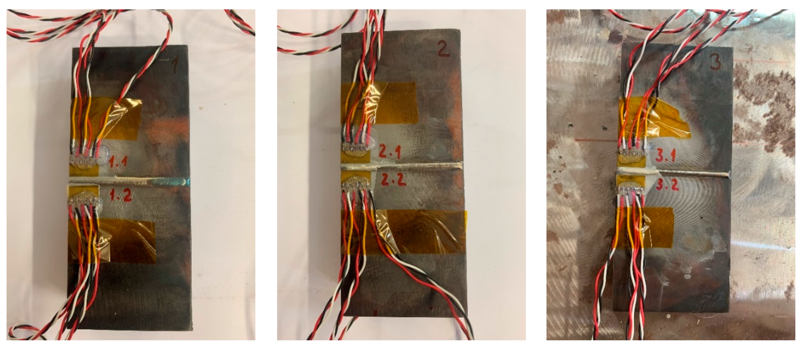
residual stresses by the drilling method;
-
light microscopy, (etchant used-3% HNO3 solution);
-
microstructure in the area of drilled holes (for the drilling method);
-
EDX analysis;
-
Clad hardness (in cross section in the plane of the drilled holes).

3. Results

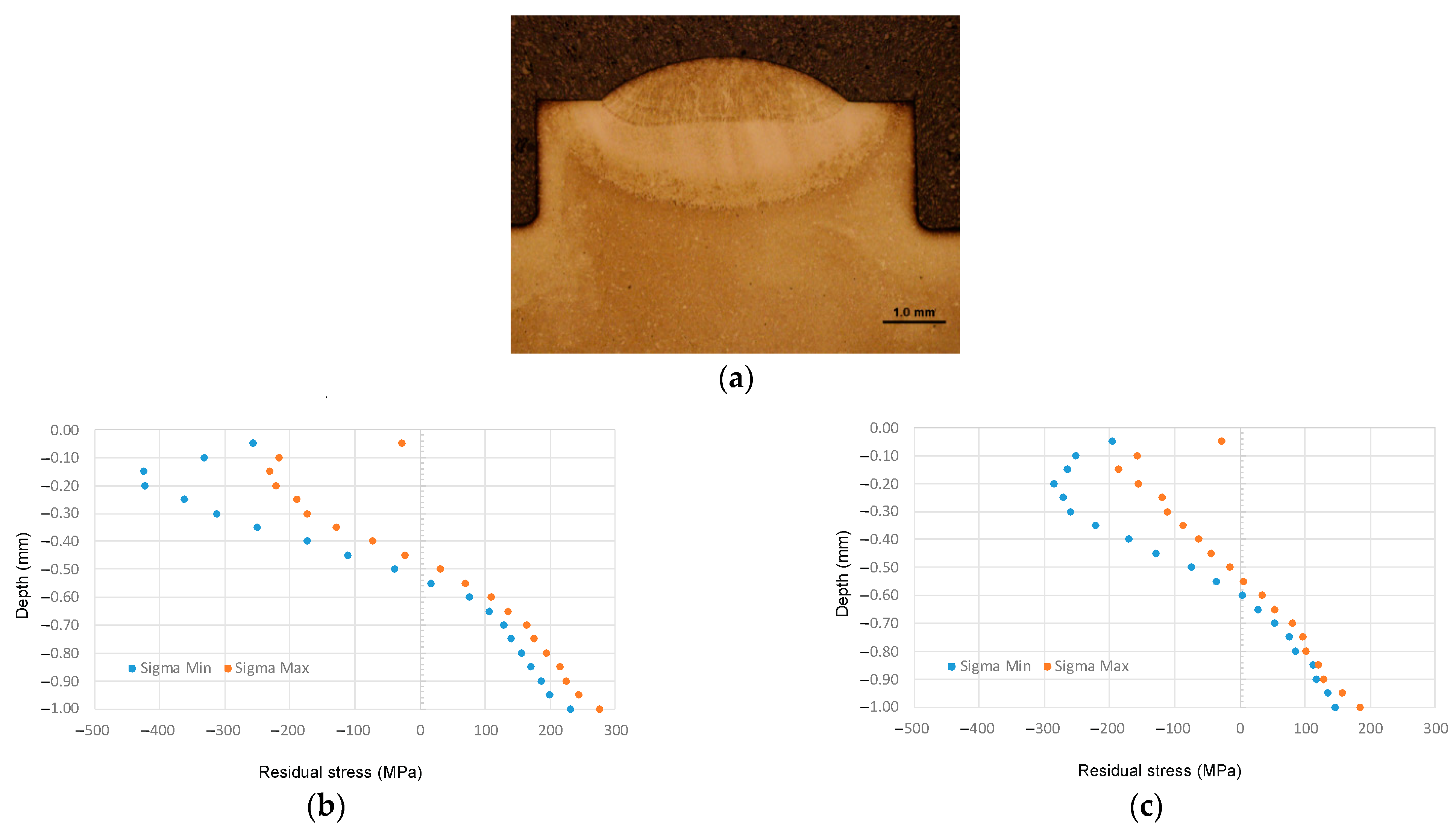
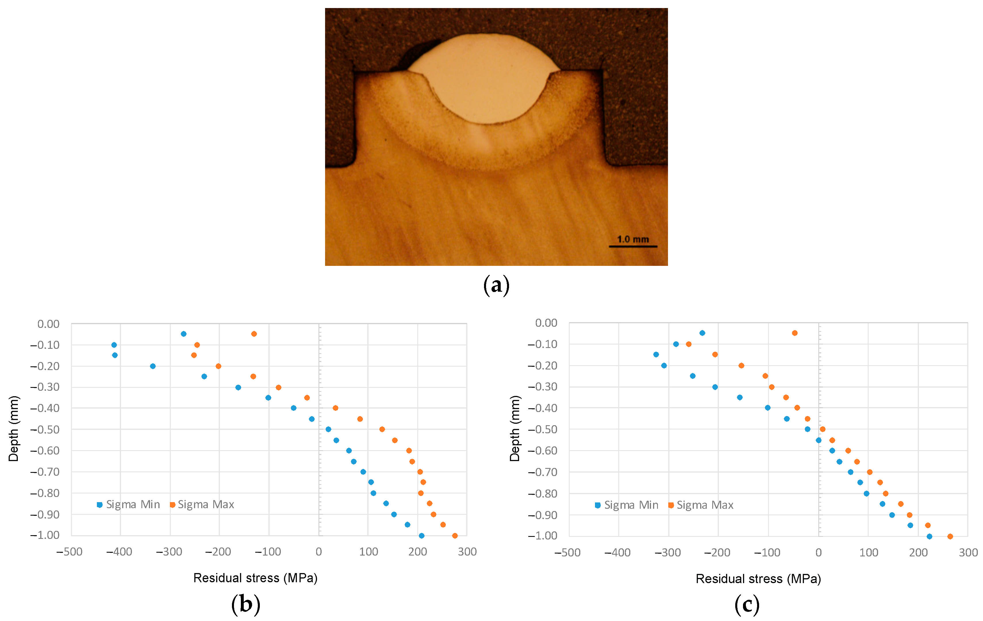
3.1. Residual Stresses

Nondestructive methods are often used for the evaluation of residual stresses around welds and are the subject of many scientific studies. The advantage of nondestructive methods is the determination of residual stresses in the subsurface layers. In the present paper, the authors chose the drilling method, which belongs to the semidestructive methods, for the determination of residual stress levels. The aim was to compare the residual stresses along the depth of the material of the test specimens depending on the chosen method of clad technology.
For the drilling method, strain gauge sensors type 1-RY61-1.5/120R (HBM, Germany), drilling cutters with a diameter of ø 1.6 mm type 1-SINTCTT-1 (SINT Technology, Italy) and drilling equipment SINT MTS 3000 with a turbine driven by compressed air (SINT Technology, Italy) were used. In order to achieve the most accurate results, a new cutter was used at each drilling location. For the processing of the name-wound relaxed strain ratios, the EVAL 7.0 software was used to evaluate the residual stress levels in accordance with ASTM E837. In addition to the normalized results, this software also provides an evaluation of the measured relaxed ratio strains by the integral method. Figure 1 shows the location of the measurement points on the single-individual specimens where the residual stresses were evaluated. The measurement locations were selected at the same distance from the edge of each test specimen. For the experimental measurements, three specimens with different additive laser-coating materials (Dievar, Dratec, UTPA 702) were used.
Figure 2a, Figure 3a and Figure 4a show details of the evaluated areas in which residual stress values were measured. The plots (Figure 2b,c, Figure 3b,c and Figure 4b,c) document the distribution of the maximum and minimal normal residual stresses to a depth of 1 mm from the sample surface. The results presented were evaluated in accordance with ASTM E837.
Measured values of the residual stresses can be considered relevant at each measured location, because, in neither case, the value exceeded 80% of the yield strength of the material. The maximum values of the reduced stresses, according to Von Mises, were 345 MPa for the Dievar additive material (location 1.1), 324 MPa for the Dratec additive material (location 2.1), and 363 MPa for the UTPA 702 additive material (location 3.2). Interestingly, at each of the six sites measured, the maximum values were 0.15 mm and 0.2 mm in depth, respectively. Another common feature of the experimental measurements is that the nature of the residual stresses changed from compressive to tensile also at approximately the same depth below the surface, around 0.5 mm.

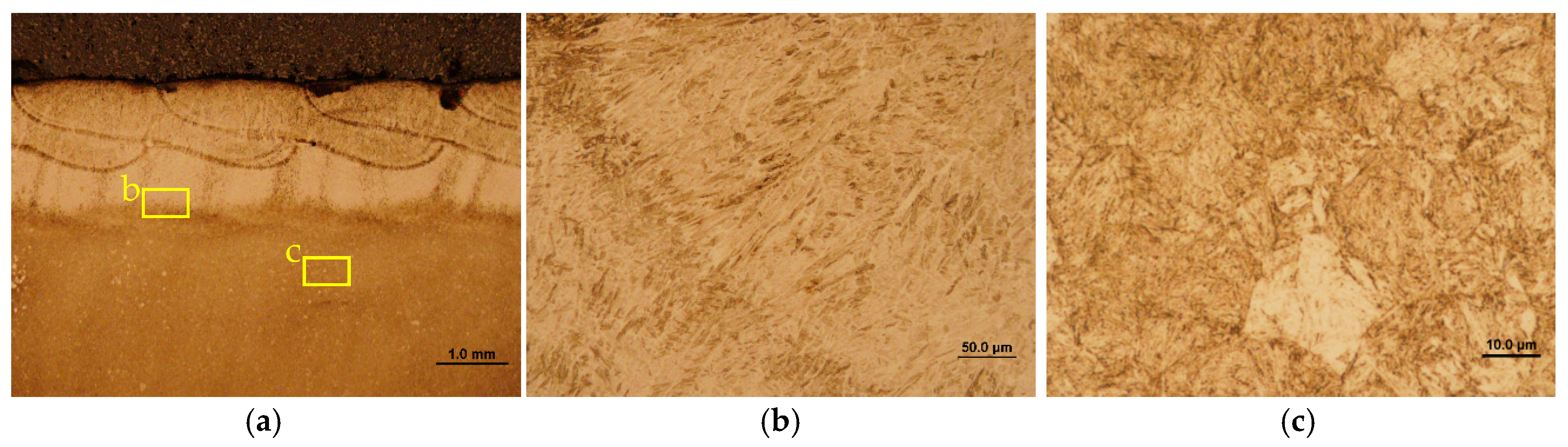
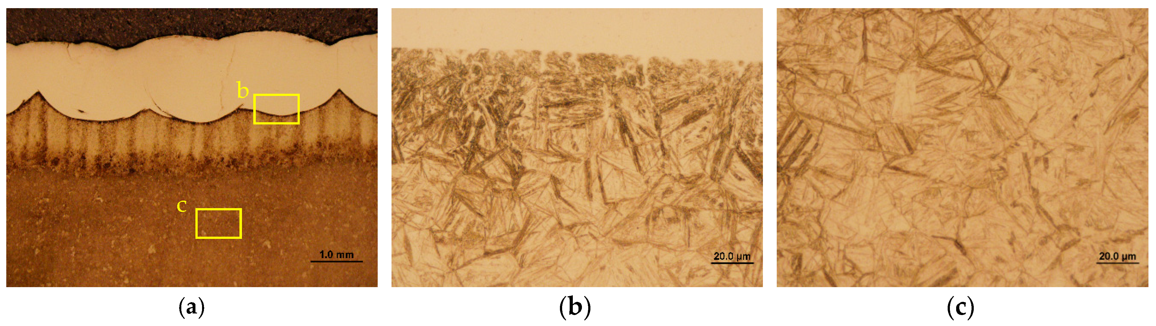
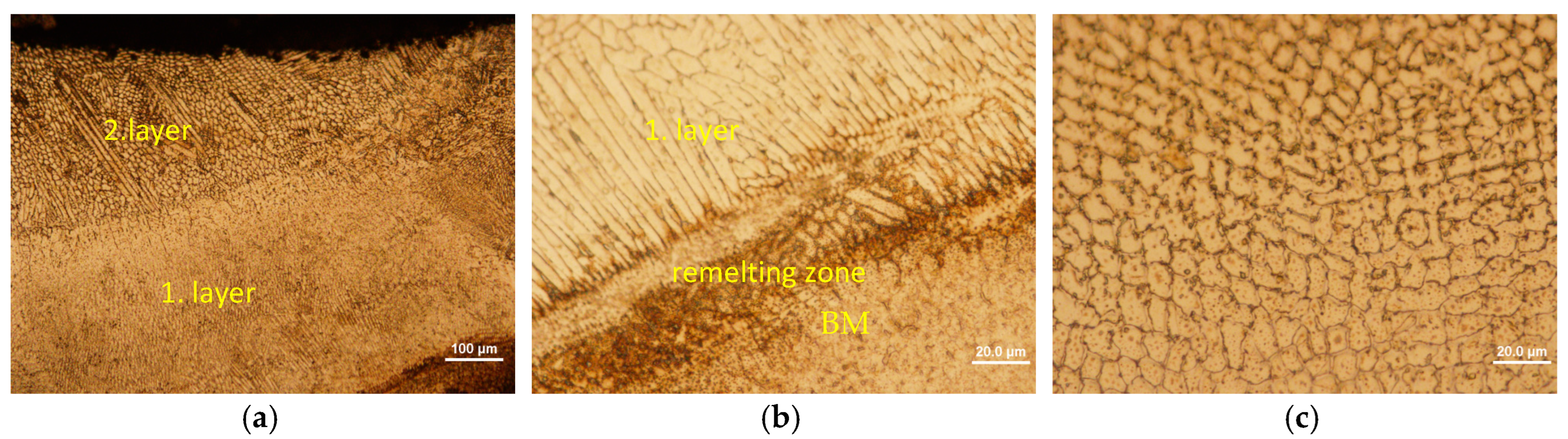
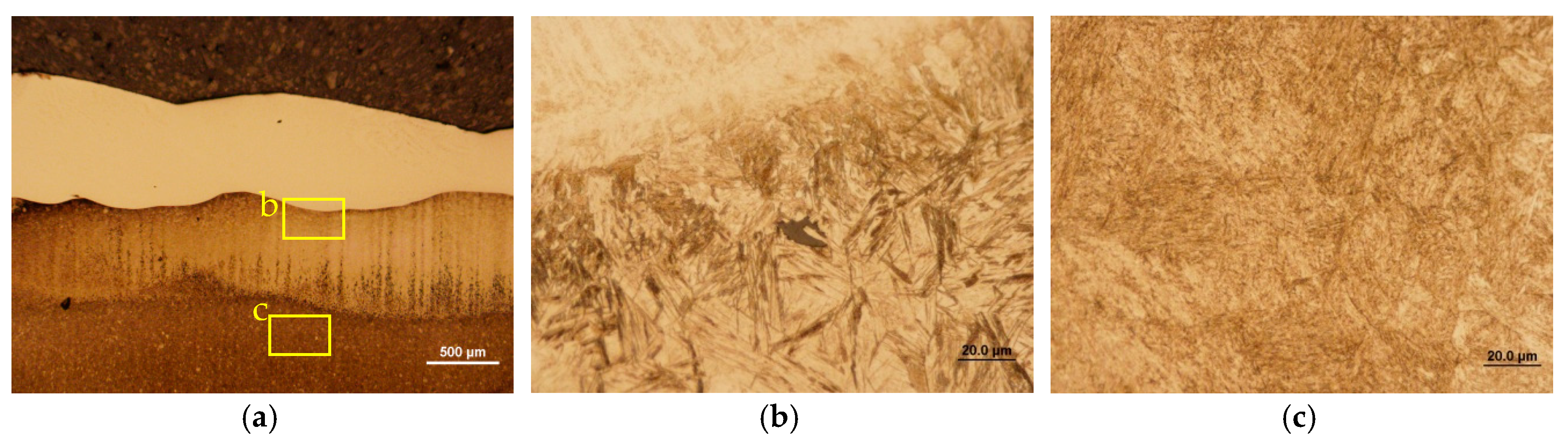
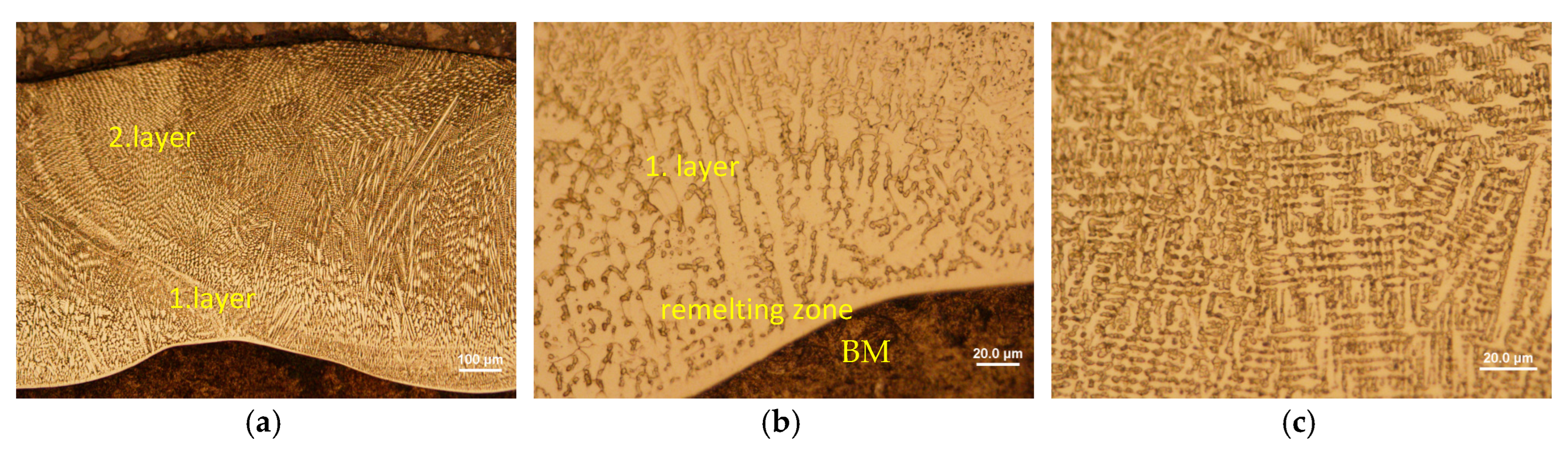
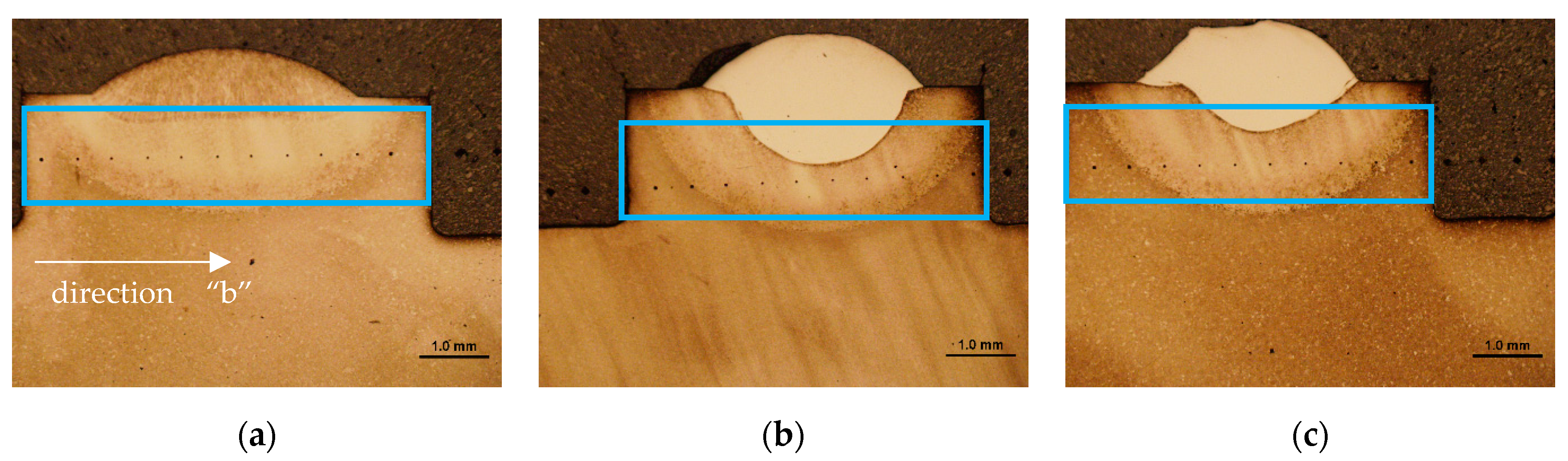
3.2. Light Microscopy

A light-microscopy technique was used to examine the microstructures on the cross-sections of the clads in the magnification range of 25x to 1000x. The inspection of the clads was focused on the identification of defects and nonintegrity.
The additive material No. 1.2343-Dievar. HAZ thickness was a max. of 1 mm. The microstructure in the clad was tempered martensite with directed crystallization, without integrity defects, melt zone without integrity defects and anomalies in the microstructure, in the HAZ gradual transition from a ferritic–carbide mixture to a tempered martensite microstructure of the underlying matrix (Figure 5 and Figure 6).
The clad 1.6356-UTPA 702. HAZ thickness was a max. of 1.0 mm. The microstructure in the clad casting with directed crystallization (visible in scanning electron microscope in BSE mode), without integrity defects, HAZ-without integrity defects, build zone without integrity defects, and base material tempered martensite microstructure without integrity defects (Figure 7, Figure 8, Figure 9 and Figure 10).
The clad 1.6356-Dratec. HAZ thickness was a max. of 1.0 mm. The microstructure in the clad casting with directed crystallization (visible in scanning electron microscope in BSE mode), without integrity defects, HAZ-without integrity defects, build zone without deintegrity defects, and substrate material tempered martensite microstructure without integrity defects (Figure 11, Figure 12 and Figure 13).

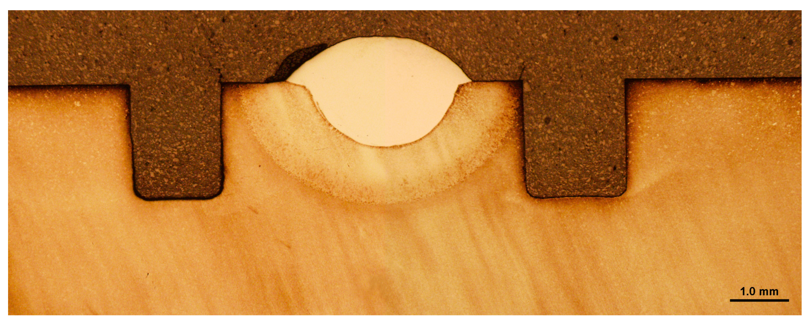
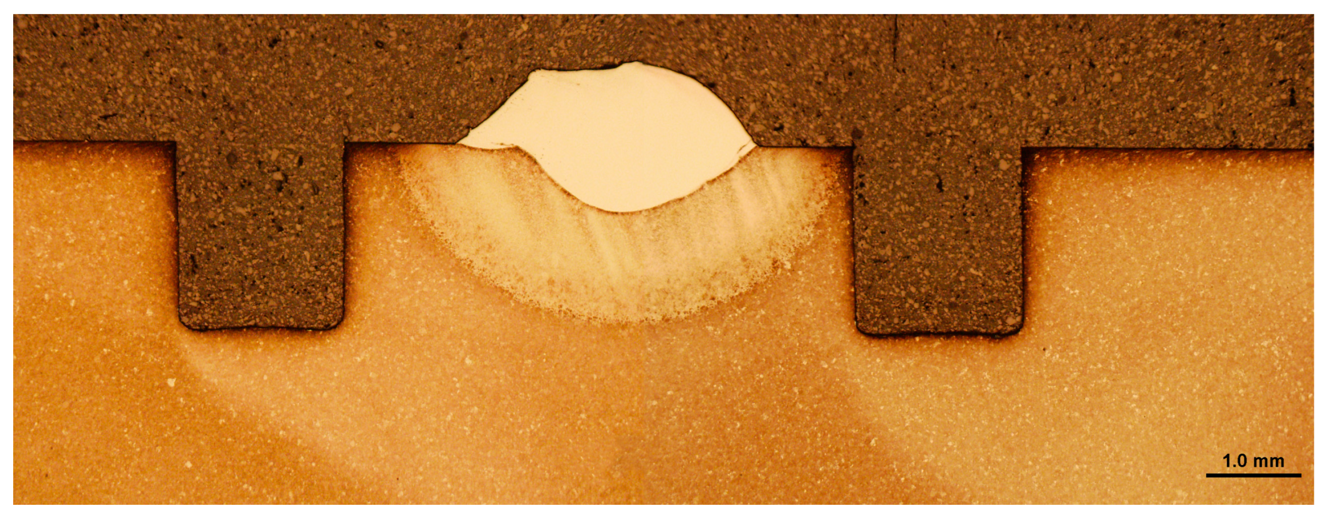
3.3. Microstructure in the Area of Drilled Holes

In Figure 14, the areas of the test specimen with clad coating 1.2343 are documented sequentially from the vicinity of the experimental holes through the microstructure in the thermally affected zone to the thermally unaffected zone of the base material. In Figure 15, there are gradually documented areas of the testing sample with a clad 1.6356 Dratec coating documented sequentially from the vicinity of the experimental holes through the microstructure in the thermally influenced zone to the thermally unaffected zone of the base material. In Figure 16, the areas of the test sample with the clad coating 1.6356 UTPA 702 are documented sequentially from the vicinity of the experimental holes through the microstructure in the thermally affected zone to the thermally unaffected zone of the base material.
Figure 14, Figure 15 and Figure 16 document the macrostructures and details of microstructures in selected areas of the single-layer single-caterpillar laser-fabricated clad. Based on the evaluation of the cross-sectional sections of the macrostructures, it can be concluded that the cladding parameters used allowed the formation of a compatible, defect-free layer in all the samples evaluated. The heat-affected zone is well-legible after etching and corresponds to the applied etching technology. The smallest depth of the heat-affected area was observed on the clads made with 1.2343 additive material, namely 0.5 mm. The columnar structure and dihedral angle of the surfacing metal were well readable on the surfacing made with this additive material. The specimen made with Dratec additive material showed the highest elevations and symmetrical cladding. Shape irregularity at the postpeak of the overlay was noted on the specimen made with UTPA 702 additive material. This shape granularity was not observed over the entire surface of the clad. It was an isolated defect. The changes in the structures of the materials evaluated correspond to metallurgical changes in the given chemical compositions of these steel types and also to the cladding technology used.

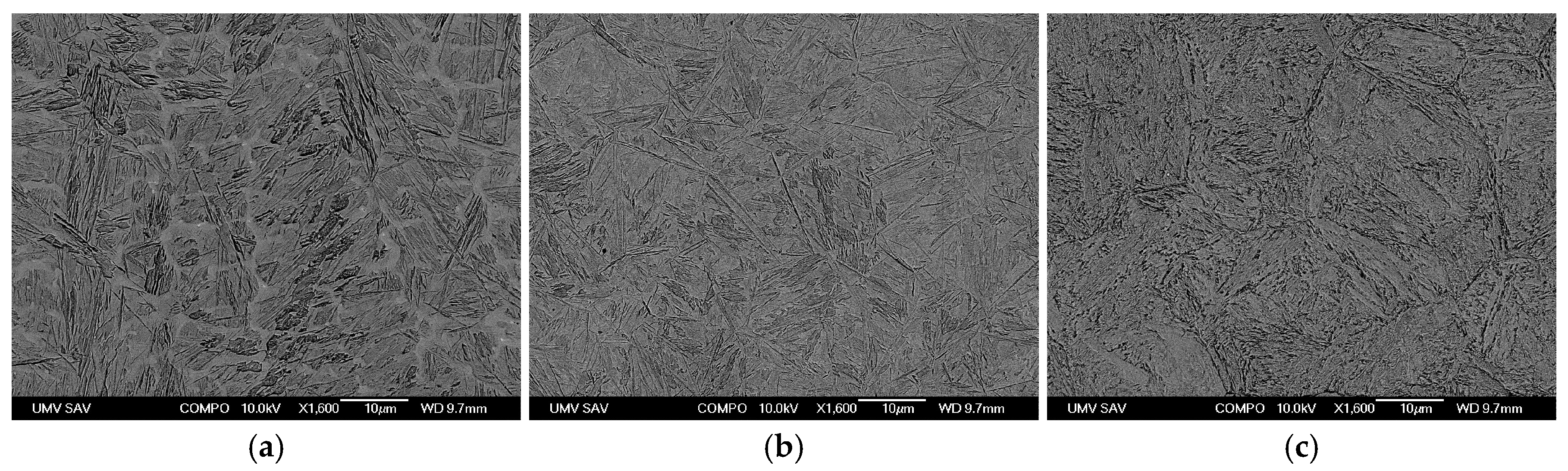
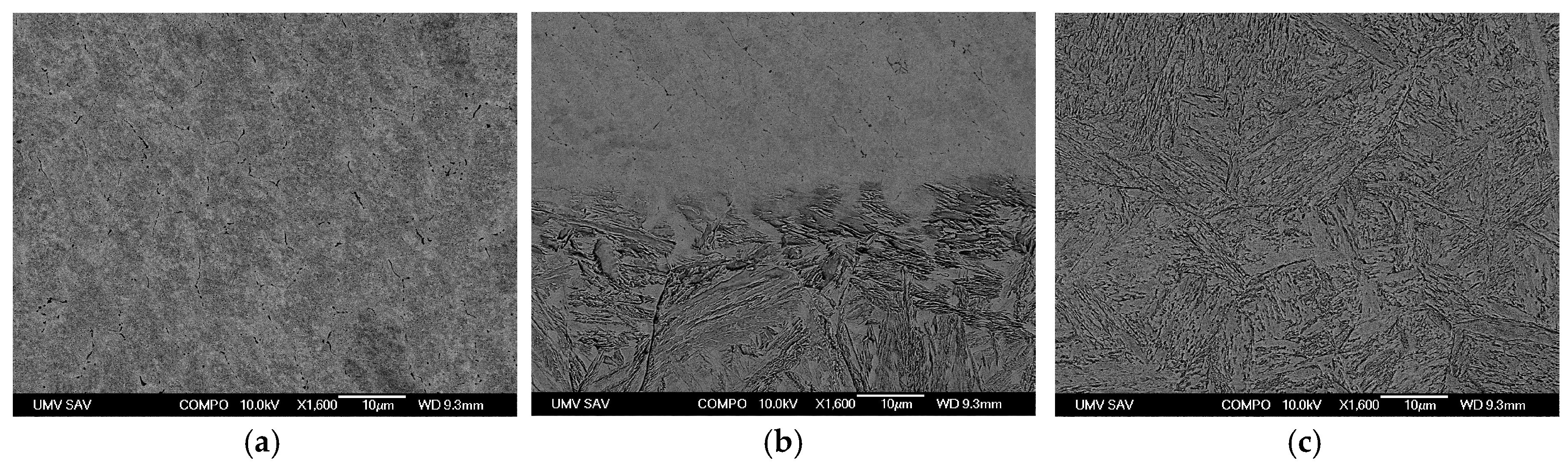
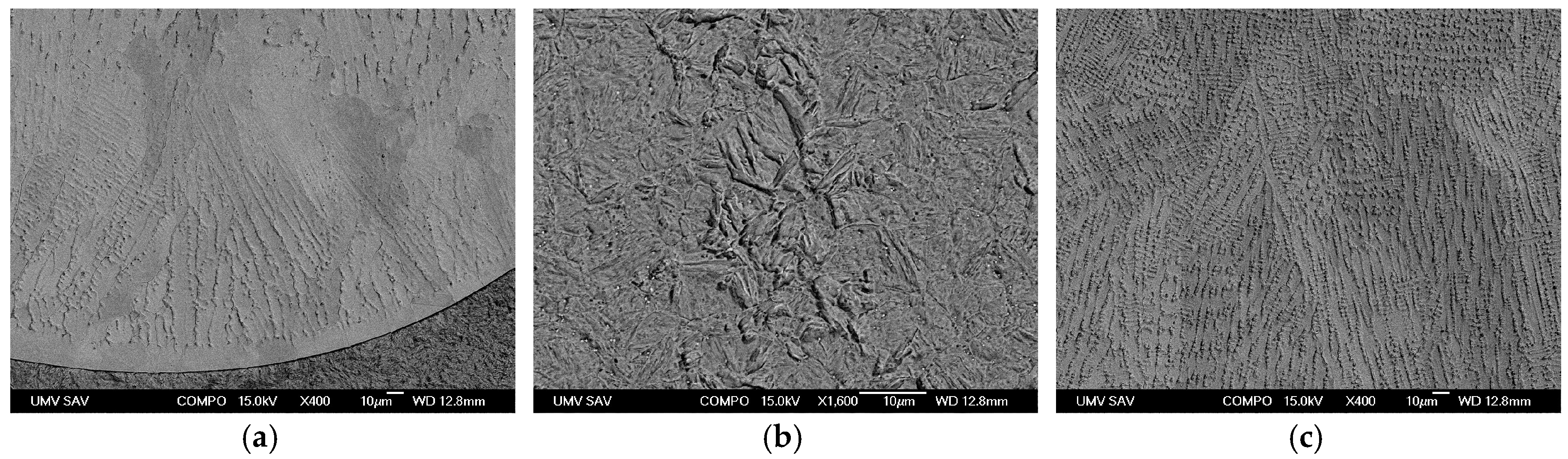
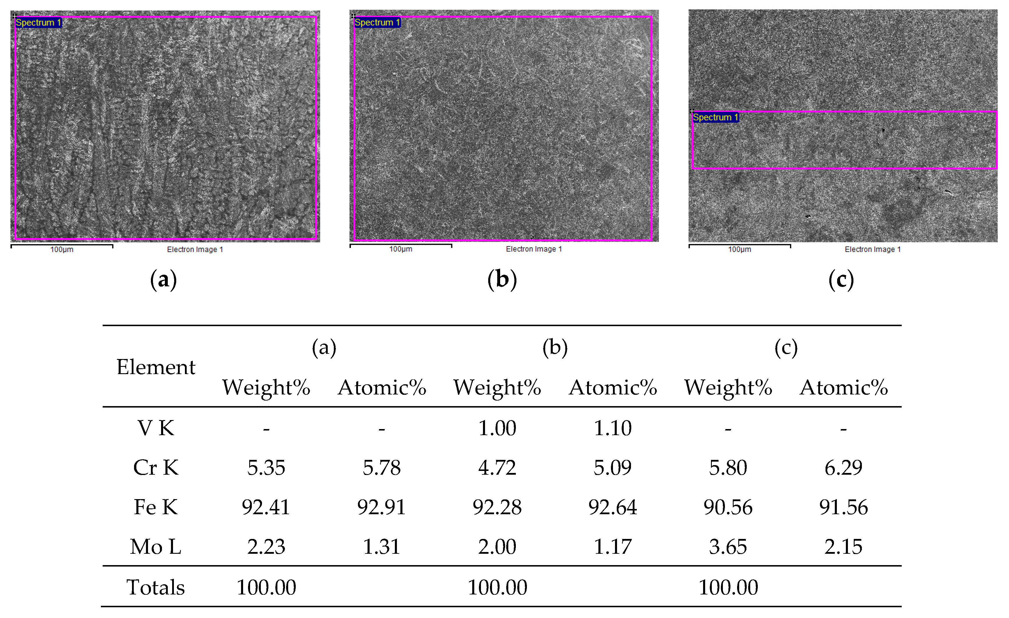
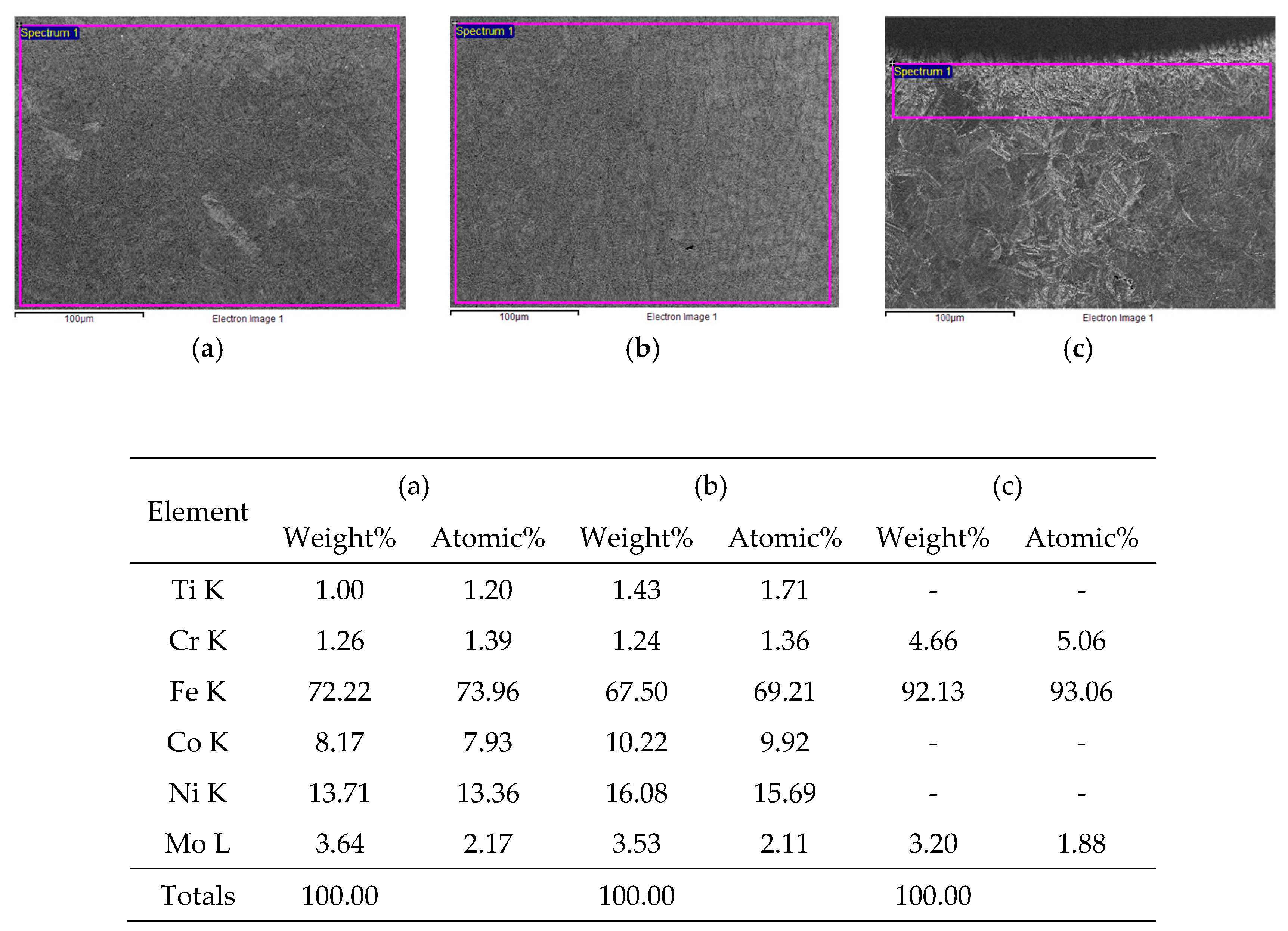
3.4. Scanning Electron Microscopy and EDX Microanalysis

Scanning electron microscopy technique and semiquantitative EDX microanalyses were used to analyse the distribution of alloys in the No. 1.2343 Dievar, No. 1.6356-UTPA 702, and No. 1.6356-Dratec strands. The chemical composition of the alloys and the effect of technology on the mixing of the alloying metal were evaluated by EDX analyses. The individual analyses and their results are documented in Figure 17, Figure 18 and Figure 19. The identified chemical-element contents are consistent with the chemical composition of the additive materials.
On the basis of the EDX analyses carried out in the individual selected spectra, it can be concluded that the chemical composition of the additives corresponds to the chemical composition of the additive materials used. Due to the cladding technology and parameters used, there was only minimal mixing of the clad metal with the base material, which is consistent with the measured HAZ values presented in Section 3.2. When using the energy-beam laser-cladding method, there was no burning of the elements during their transfer to the clad metal as occurs with arc methods. Also, no oxidation or contamination of the clad metal due to insufficient protection of the cladding site was observed.

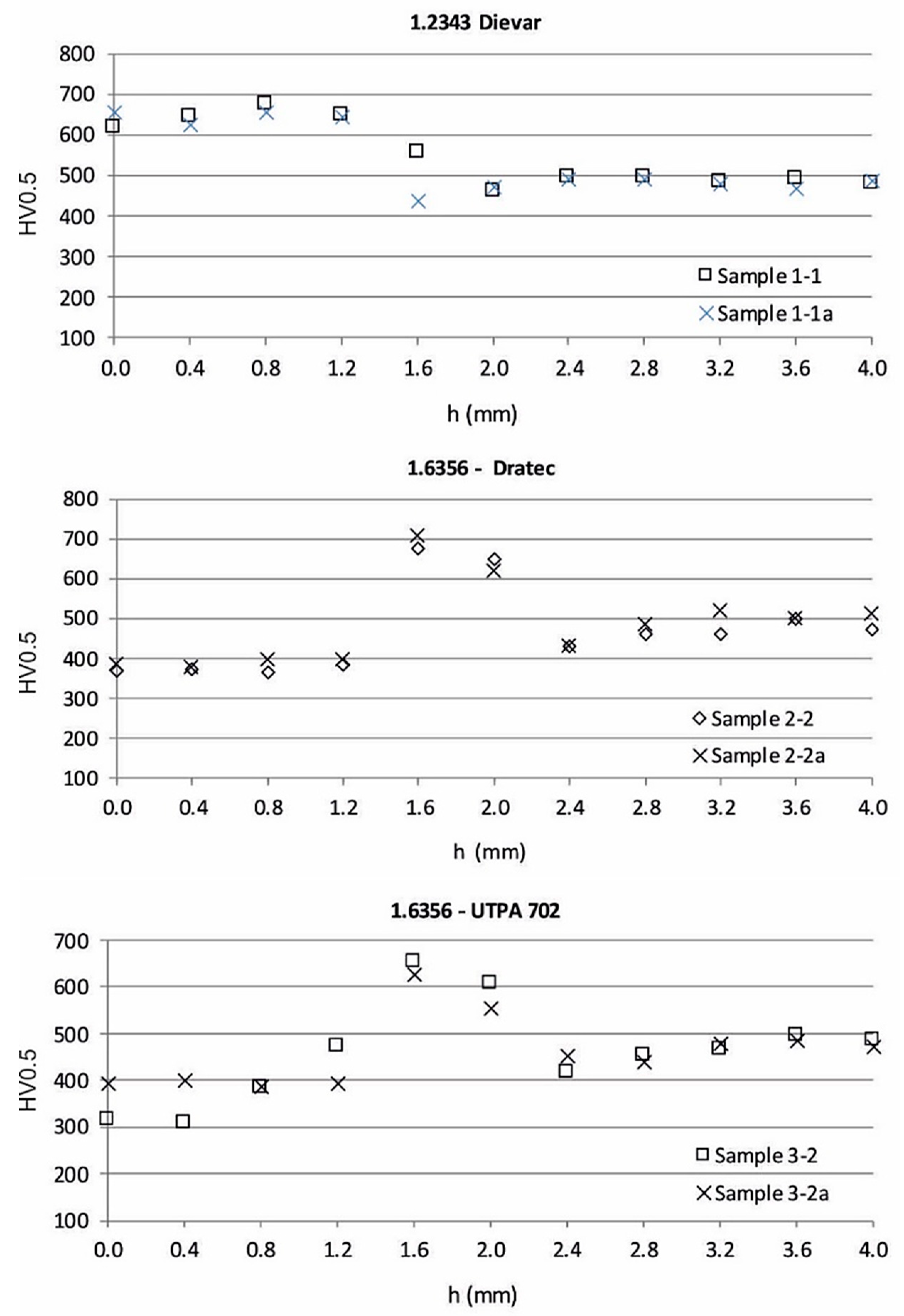
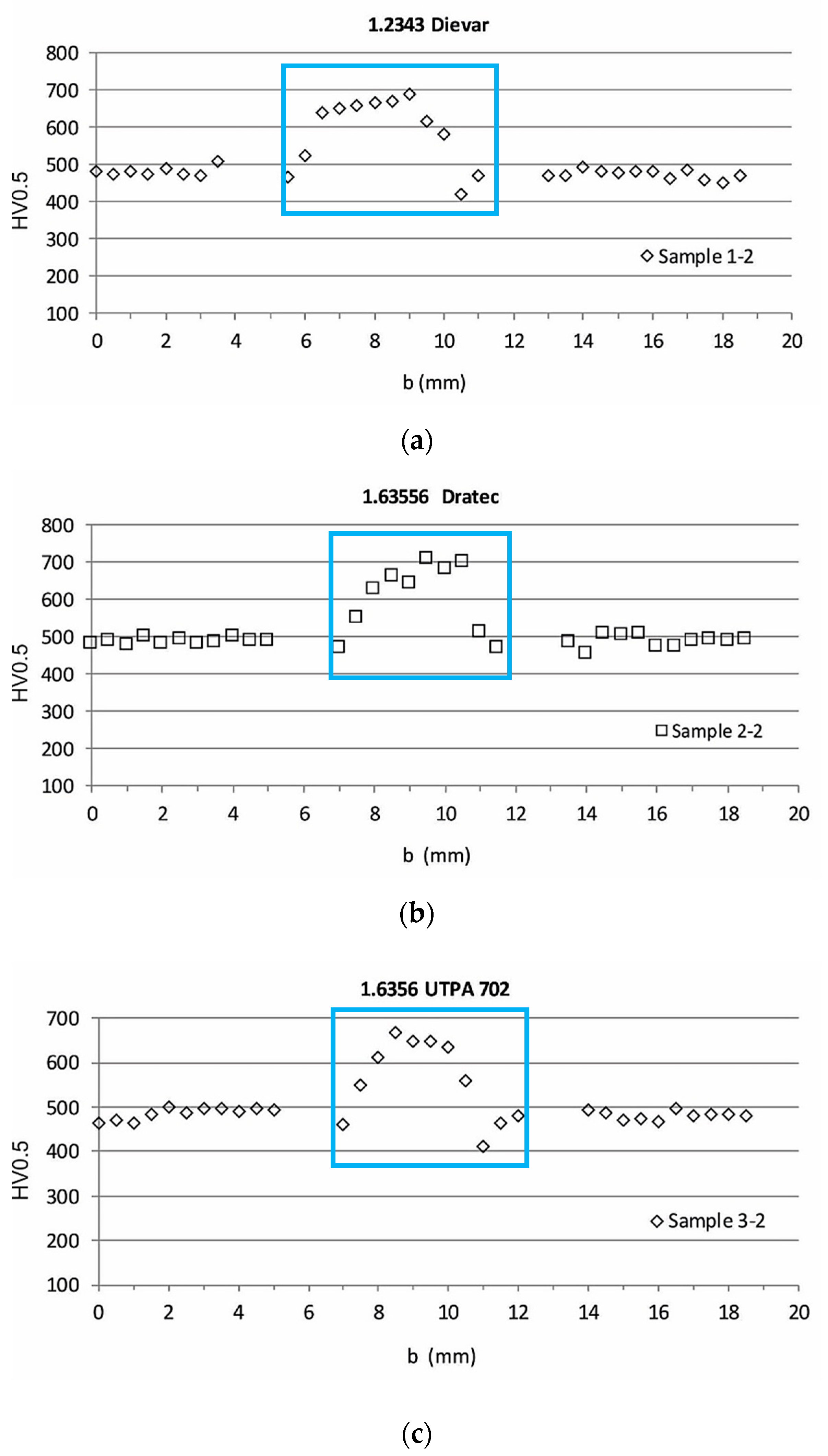
3.5. Results of Hardness Measurement of Clads

Hardness measurements were performed according to the Vickers indentor at a load of 500 g and an indentor indentation distance of 0.4 mm. The plots of the measured hardness values on the cross-sections of the test specimens are shown in Figure 20. Two hardness measurements from the surface to the substrate layer were performed on each specimen. For the 1.2343 clad specimen, a hardness value of 600 HV0.5 was measured at the surface of the clad. A maximum hardness value of 700 HV0.5 was measured at a depth of 0.8 mm. For the 1.6356-Dratec and 1.6356-UTPA 702 clad specimens, maximum hardness values in the range of 600 to 700 HV0.5 were measured at a depth of 1.6 to 2.0 mm. From the surface of the clad to a depth of 1.2 mm, the hardness was 400 HV0.5.
A hardness measurement of HV0.5 was performed on the cross sections of the specimens previously used for the measurement of the residual stresses by drilling, see Figure 21. The measurement line was at a depth of 0.4 mm below the surface of the substrate plate and crossed the cross sections (horizontal line “b”). The Vickers indenter impressions were spaced 0.4 mm apart. Increased hardness values were measured in the centre of HAZ, see Figure 22 (blue area). The locations without measured microhardness values correspond to the blind holes.
The measured hardness values in the horizontal lines of the specimens used to measure the residual stresses are consistent with the measured values in the given clad area (sub-base areas) measured vertically.

4. Discussion

The presented results provide a comprehensive view of the distribution of residual stresses in the vicinity of the clad not only in the surface layers but also to a greater depth from the surface (on the order of 1 mm). For the realization of the experimental measurements, the drilling method was used, which is commonly used for the quantification of residual stresses in many applications where residual stress levels need to be taken into account for the assessment of the safe and reliable operation of machinery and equipment. The advantage of the above method is that the measurement and evaluation procedure is standardized (ASTM E837). In addition to the residual stresses, the hardness and microstructure of the material were also analysed at the measurement locations.
On the basis of the analysis of the results obtained, the following conclusions can be drawn:
In the case of the application of the additive materials No. 1.2343 Dievar, No. 1.6356 Dratec and No. 1.6356 UTPA 702 by laser to the considered base material No. 1.2343 Dievar, the residual stresses showed a similar character. In each of the specimens considered, the residual stresses were evaluated at the same distance from the edge of the clad in accordance with ASTM E837 procedures. The measured values of residual stresses can be considered relevant at each measured location, because in no case was the value of 80% yield strength of the material exceeded. The maximum values of the reduced stresses according to Von Mises were 345 MPa for the Dievar additive material (location 1.1), 324 MPa for the Dratec additive material (location 2.1), and 363 MPa for the UTPA 702 additive material (location 3.2). Interestingly, at each of the six sites measured, the maximum values were 0.15 mm and 0.2 mm in depth, respectively. Another common feature of the experimental measurements is that the nature of the residual stresses changed from compressive to tensile also at approximately the same depth below the surface, around 0.5 mm.
The light-microscopy technique was used to examine the microstructures on the cross sections of the clads in the magnification range of 25x to 1000x. The inspection of the clads was focused on the identification of defects and nonintegrity of the clads. None of the samples analysed showed any defects or signs of defects.
The microstructure of the base material No. 1.2343 after heat treatment is tempered martensite. In the clad made by additive material 1.2343, the structure was tempered martensite with directed crystallization without integrity defects. The melting zone, without defects of integrity and anomalies in the microstructure, had the HAZ gradual transition from a ferritic–carbide mixture to tempered martensite microstructure of the base material. The thickness of the HAZ was max. 0.5 mm. The microstructure in the 1.6356-UTPA 702 clad was classified as casting with directed crystallization (visible in a scanning electron microscope in BSE mode), without integrity defects, and HAZ without integrity defects. The melting zone was without integrity defects; the base material had microstructure-tempered martensite also without integrity defects. The HAZ thickness was a max. of 1.0 mm. A similar type of casting structure was observed on the sample with the 1–6356 Dratec clad. The HAZ thickness was also similar (max. 1.0 mm).
The influence of cladding technology and parameters on the chemical composition of the newly formed layers was evaluated by area EDX analyses. The measurements made show that the influence of layer production did not lead to changes in the chemical composition of the produced layers compared to the declared chemical composition of the additive materials.
Hardness measurements were performed on crosscuts according to Vickers. The maximum hardness values measured on the clad were 700 HV0.5 at a depth of 0.8 mm for the 1.2343 specimen. The hardness at the surface of the clad was 600 HV0.5. For functional areas of the moulds, it is suitable if the maximum hardness is located at the surface of the functional area and the subsurface areas possess higher toughness. For the clads 1.6356-Dratec and 1.6356-UTP A702, maximum hardness values were in the range of 600 to 700 HV0.5 measured at a depth of 1.6 to 2.0 mm, which will be the subject of further research. From the surface of the clad to a depth of 1.2 mm, the hardness value was 400 HV0.5.
A hardness measurement of HV0.5 was made on the transverse sections of the specimens previously used for the measurement of residual stresses by drilling. The horizontal line of measurement was at a depth of 0.4 mm below the surface of the base plate and crossed the clads. The indentations of the Vickers indenter were spaced 0.4 mm apart (Figure 16). The measured hardness values of up to 700 HV0.5 were consistent with the measured hardness values in the vertical direction.

5. Conclusions

The refurbishment of functional component surfaces is currently a hot topic. As the prices of steels, especially high-quality tool steels, are steadily rising worldwide, the refurbishment of functional parts of machinery and equipment is on the rise. Particularly advantageous is the renovation of dimensional parts or the creation of functional surfaces that have significantly better mechanical properties and resistance to tribodegradation agents compared to the underlying materials.
This paper presents the results of an investigation aimed at determining the quality of three additive materials of medium- and high-alloy steels suitable for the refurbishment of moulds for the high-pressure casting of Al alloys. On the basis of the experimental results, it is possible to establish our conclusions.
The distribution of residual stresses along the depth of the base material shows a comparable character in all three samples. At a depth of about 0.2 mm, the maximum value of compressive residual stress was measured at each measured location. In the case of UPTA 702, the residual stress values from both sides of the strand exceeded 400 MPa. An interesting common feature is the change in the nature of the residual stresses from compressive to tensile at a depth of about 0.6 mm. The compressive residual stresses can be considered positive in terms of crack propagation.
On the basis of the experiments carried out and the study of the structure of the additive materials, it is suitable to apply for the restoration of functional surfaces of clads, the structure of which after heat treatment is formed by loosened martensite. This type of structure achieves the hardness necessary for a given method of loading. The aim is to achieve a suitable structure of the surface layers, which is a tempered martensite, and a hardness in the range 44–48 HRc. The aim of this paper was to present the procedures and results of research focused on the area of surface renovation.
The research on the increase of mould lifetime is currently continued by the evaluation of the surface resistance to material dissolution by immersion test in an Al melt. The possibilities of increasing the effect of separation agents and surface texturing by laser are analysed.

Author Contributions

Conceptualization, J.V., M.P. and P.Š.; methodology, J.B. (Janette Brezinová), M.D., M.P. and P.Š.; validation, P.Š. and M.P.; formal analysis, P.Š. and M.P.; investigation, P.Š., M.P. and J.B. (Jakub Brezina); resources, M.D., P.Š., J.B. (Janette Brezinová) and J.V.; draft preparation, P.Š. and J.V.; writing—review and editing, P.Š. and J.V.; visualization, P.Š. and J.V.; project administration, J.B. (Janette Brezinová); funding acquisition, J.B. (Jakub Brezina). All authors have read and agreed to the published version of the manuscript.

Funding

This contribution is the result of the project implementation: Innovative approaches of the restoration of functional surfaces by laser weld overlaying APVV-20-0303, supported by the Slovak Research and Development Agency and supported by the Ministry of Education of Slovakia Foundation under grant projects VEGA No. 1/0597/23, VEGA No. 1/0516/22, and KEGA No. 046TUKE-4/2022.

Data Availability Statement

The data presented in this study are available on request from the corresponding author.

Conflicts of Interest

The authors declare no conflict of interest.

References

  1. Muigai, M.N.; Mwema, F.M.; Akinlabi, E.T.; Jen, T.C.; Fatoba, O.S.; Leso, T.P.; Obiko, J.O.; Mphasha, P. TIG Welding Methods of Repairing Steel Components with Stainless Steel Coatings. Tribol. Ind. 2022, 44, 434–448. [Google Scholar] [CrossRef]
  2. Ashokkumar, M.; Thirumalaikumarasamy, D.; Sonar, T.; Deepak, S.; Vignesh, P.; Anbarasu, M. An Overview of Cold Spray Coating in Additive Manufacturing, Component Repairing and Other Engineering Applications. J. Mech. Behav. Mater. 2022, 31, 514–534. [Google Scholar] [CrossRef]
  3. Brezinová, J.; Viňáš, J.; Guzanová, A.; Živčák, J.; Brezina, J.; Sailer, H.; Vojtko, M.; Džupon, M.; Volkov, A.; Kolařík, L.; et al. Selected Properties of Hardfacing Layers Created by Pta Technology. Metals 2021, 11, 134. [Google Scholar] [CrossRef]
  4. Lu, T.; Cheng, W.; Dong, S.; Ge, H.; Li, W.; He, J.; Hu, Z. Laser Additive Remanufacturing Cladding Thickness Detection System. J. Phys. Conf. Ser. 2022, 2395, 012061. [Google Scholar] [CrossRef]
  5. Trojan, K.; Ocelík, V.; Čapek, J.; Čech, J.; Canelo-yubero, D.; Ganev, N.; Kolařík, K.; De Hosson, J.T.M. Microstructure and Mechanical Properties of Laser Additive Manufactured H13 Tool Steel. Metals 2022, 12, 243. [Google Scholar] [CrossRef]
  6. Trembach, B.; Grin, A.; Makarenko, N.; Zharikov, S.; Trembach, I.; Markov, O. Influence of the Core Filler Composition on the Recovery of Alloying Elements during the Self-Shielded Flux-Cored Arc Welding. J. Mater. Res. Technol. 2020, 9, 10520–10528. [Google Scholar] [CrossRef]
  7. Viňáš, J.; Brezinová, J.; Guzanová, A. Analysis of the Quality Renovated Continuous Steel Casting Roller. Sadhana-Acad. Proc. Eng. Sci. 2013, 38, 477–490. [Google Scholar] [CrossRef]
  8. Wu, H.; Wu, R. The Role of Educational Action Research of Recycling Process to the Green Technologies, Environment Engineering, and Circular Economies. Int. J. Recent Technol. Eng. 2019, 8, 1639–1645. [Google Scholar] [CrossRef]
  9. Orečný, M.; Buršák, M.; Viňáš, J. The Influence of Heat Treatnemnt on the Abrasive Wear Resistnace of a Construction and a Tool Steel. Metalurgija 2015, 54, 5–24. [Google Scholar]
  10. Kónya, J.; Hargitai, H.; Jaber, H.; Pinke, P.; Kovács, T.A. Effect of Surface Modifications on Surface Roughness of Ti6Al4V Alloy Manufactured by 3D Printing, Casting, and Wrought. Materials 2023, 16, 3989. [Google Scholar] [CrossRef]
  11. Jiang, H.; Wang, C.; Bai, L.; Han, C.; Chen, X.; Wang, C. Advances and Prospects in Lake Environment Science and Engineering: A Review. Hupo Kexue/J. Lake Sci. 2020, 32, 1. [Google Scholar]
  12. Inagaki, M.; Nakamura, H.; Okada, A. Studies of Cooling Processes in the Cases of Welding with Coated Electrode and Submerged Arc Welding. J. Jpn. Weld. Soc. 1965, 34, 1064–1075. [Google Scholar] [CrossRef]
  13. De Paula, M.P.M.; Modenesi, P.J.; Trindade, V.B. Analysis of the Influence of Welding Parameters on Microstructures and Mechanical Properties of Welding Joints of an API X70Q Steel Tube for the Sour Service Application. Soldag. Insp. 2018, 23, 180–190. [Google Scholar] [CrossRef]
  14. Lu, X.; Cervera, M.; Chiumenti, M.; Lin, X. Residual Stresses Control in Additive Manufacturing. J. Manuf. Mater. Process. 2021, 5, 138. [Google Scholar] [CrossRef]
  15. Fang, Z.C.; Wu, Z.L.; Huang, C.G.; Wu, C.W. Review on Residual Stress in Selective Laser Melting Additive Manufacturing of Alloy Parts. Opt. Laser Technol. 2020, 129, 106283. [Google Scholar] [CrossRef]
  16. Ahmad, B.; Zhang, X.; Guo, H.; Fitzpatrick, M.E.; Neto, L.M.S.C.; Williams, S. Influence of Deposition Strategies on Residual Stress in Wire + Arc Additive Manufactured Titanium Ti-6Al-4V. Metals 2022, 12, 253. [Google Scholar] [CrossRef]
  17. De, A.; DebRoy, T. A Perspective on Residual Stresses in Welding. Sci. Technol. Weld. Join. 2011, 16, 204–208. [Google Scholar] [CrossRef]
  18. Trembach, B.; Grin, A.; Turchanin, M.; Makarenko, N.; Markov, O.; Trembach, I. Application of Taguchi Method and ANOVA Analysis for Optimization of Process Parameters and Exothermic Addition (CuO-Al) Introduction in the Core Filler during Self-Shielded Flux-Cored Arc Welding. Int. J. Adv. Manuf. Technol. 2021, 114, 1099–1118. [Google Scholar] [CrossRef]
  19. Viňáš, J.; Brezinová, J.; Guzanová, A.; Balog, P. Evaluation of the Quality of Cladding Deposited on Continuous Steel Casting Rolls. Int. J. Mater. Res. 2013, 104, 183–191. [Google Scholar] [CrossRef]
  20. Viňáš, J.; Brezinová, J.; Brezina, J.; Maruschak, P.O. Structural and Mechanical Features of Laser-Welded Joints of Zinc-Coated Advanced Steel Sheets. Mater. Sci. 2019, 55, 46–51. [Google Scholar] [CrossRef]
  21. Schubnell, J.; Carl, E.; Farajian, M.; Gkatzogiannis, S.; Knödel, P.; Ummenhofer, T.; Wimpory, R.; Eslami, H. Residual Stress Relaxation in HFMI-Treated Fillet Welds after Single Overload Peaks. Weld. World 2020, 64, 1107–1117. [Google Scholar] [CrossRef]
  22. Kovács, T.A.; Pinke, P.; Bitay, E. Experimental Study of the Technology Parameters Affect in the Laser Welded Joints. IOP Conf. Ser. Mater. Sci. Eng. 2019, 613, 012038. [Google Scholar] [CrossRef]
  23. Dománková, M.; Adamech, M.; Petzová, J.; Bártová, K.; Pinke, P. Microstructure Characteristics of Borated Austenitic Stainless Steel Welds. Res. Pap. Fac. Mater. Sci. Technol. Slovak Univ. Technol. 2018, 26, 45–52. [Google Scholar] [CrossRef]
  24. Xin, H.; Veljkovic, M. Residual Stress Effects on Fatigue Crack Growth Rate of Mild Steel S355 Exposed to Air and Seawater Environments. Mater. Des. 2020, 193, 108732. [Google Scholar] [CrossRef]
  25. Sun, Y.L.; Vasileiou, A.N.; Pickering, E.J.; Collins, J.; Obasi, G.; Akrivos, V.; Smith, M.C. Impact of Weld Restraint on the Development of Distortion and Stress during the Electron Beam Welding of a Low-Alloy Steel Subject to Solid State Phase Transformation. Int. J. Mech. Sci. 2021, 196, 106244. [Google Scholar] [CrossRef]
  26. Trembach, B.; Grin, A.; Subbotina, V.; Vynar, V.; Knyazev, S.; Zakiev, V.; Trembach, I.; Kabatskyi, O. Effect of Exothermic Addition (Cuo-Al) on the Structure, Mechanical Properties and Abrasive Wear Resistance of the Deposited Metal during Self-Shielded Flux-Cored Arc Welding. Tribol. Ind. 2021, 43, 452–464. [Google Scholar] [CrossRef]
  27. Dománková, M.; Kocsisová, E.; Slatkovský, I.; Pinke, P. The Microstructure Evolution and Its Effect on Corrosion Properties of 18Cr-12Ni-2,5Mo Steel Annealed at 500–900 °C. Acta Polytech. Hung. 2014, 11, 125–137. [Google Scholar] [CrossRef]
  28. Rong, Y.; Huang, Y.; Wang, L. Evolution Mechanism of Transient Strain and Residual Stress Distribution in Al 6061 Laser Welding. Crystals 2021, 11, 205. [Google Scholar] [CrossRef]
  29. Thibault, D.; Bocher, P.; Thomas, M. Residual Stress and Microstructure in Welds of 13%Cr-4%Ni Martensitic Stainless Steel. J. Mater. Process. Technol. 2009, 209, 2195–2202. [Google Scholar] [CrossRef]
  30. Sarafan, S.; Wanjara, P.; Lévesque, J.B.; Gholipour, J.; Champliaud, H.; Mathieu, L. Through-Thickness Residual Stresses, Microstructure, and Mechanical Properties of Electron Beam-Welded CA6NM Martensitic Stainless Steel after Postweld Heat Treatment. Adv. Mater. Sci. Eng. 2020, 2020, 7194214. [Google Scholar] [CrossRef]
  31. Aung, M.P.; Katsuda, H.; Hirohata, M. Fatigue-Performance Improvement of Patch-Plate Welding via PWHT with Induction Heating. J. Constr. Steel Res. 2019, 160, 280–288. [Google Scholar] [CrossRef]
  32. Nagai, T.; Kawai, S.; Shindo, M.; Okano, S.; Mochizuki, M.; Suga, T. Comparative Study on Internal Residual Stresses in Electron Beam Welds. ISIJ Int. 2017, 57, 1072–1079. [Google Scholar] [CrossRef]
  33. Kovács-Coskun, T.; Pinke, P. The Effect of Microstructure on the Local Wear Behavior of Dual Phase Steels. IOP Conf. Ser. Mater. Sci. Eng. 2013, 47, 012032. [Google Scholar] [CrossRef]
  34. Cattivelli, A.; Roy, M.J.; Burke, M.G.; Dhers, J.; Lee, T.L.; Francis, J.A. Internal Stresses in a Clad Pressure Vessel Steel during Post Weld Heat Treatment and Their Relevance to Underclad Cracking. Int. J. Press. Vessels Pip. 2021, 193, 104448. [Google Scholar] [CrossRef]
  35. Vrancken, B. Study of Residual Stresses in Selective Laser Melting. Ph.D. Thesis, KU Leuven, Leuven, Belgium, 2016. [Google Scholar]
  36. Monin, V.I.; Lopes, R.T.; Turibus, S.N.; Payão Filho, J.C.; De Assis, J.T. X-ray Diffraction Technique Applied to Study of Residual Stresses after Welding of Duplex Stainless Steel Plates. Mater. Res. 2014, 17, 64–69. [Google Scholar] [CrossRef]
  37. Ahmed, I.I.; Adebisi, J.A.; Abdulkareem, S.; Sherry, A.H. Investigation of Surface Residual Stress Profile on Martensitic Stainless Steel Weldment with X-ray Diffraction. J. King Saud Univ.-Eng. Sci. 2018, 30, 183–187. [Google Scholar] [CrossRef]
  38. Trebuňa, F.; Šimčák, F.; Bocko, J.; Šarga, P.; Trebuňa, P.; Pástor, M.; Mihok, J. Quantification of Residual Stresses in the Weld by the Hole-Drilling Method. Metalurgija 2008, 47, 133–137. [Google Scholar]
  39. Van Puymbroeck, E.; Nagy, W.; Schotte, K.; Ul-Abdin, Z.; De Backer, H. Determination of Residual Welding Stresses in a Steel Bridge Component by Finite Element Modeling of the Incremental Hole-Drilling Method. Appl. Sci. 2019, 9, 536. [Google Scholar] [CrossRef]
  40. Zhang, H.; Li, L.; Ma, W.; Luo, Y.; Li, Z.; Kuai, H. Effects of Welding Residual Stresses on Fatigue Reliability Assessment of a PC Beam Bridge with Corrugated Steel Webs under Dynamic Vehicle Loading. Structures 2022, 45, 1561–1572. [Google Scholar] [CrossRef]
  41. Chiocca, A.; Frendo, F.; Aiello, F.; Bertini, L. Influence of Residual Stresses on the Fatigue Life of Welded Joints. Numerical Simulation and Experimental Tests. Int. J. Fatigue 2022, 162, 106901. [Google Scholar] [CrossRef]
  42. Xiong, Q.; Smith, M.C.; Muransky, O.; Mathew, J. Validated Prediction of Weld Residual Stresses in Austenitic Steel Pipe Girth Welds before and after Thermal Ageing, Part 2: Modelling and Validation. Int. J. Press. Vessels Pip. 2019, 172, 430–448. [Google Scholar] [CrossRef]
  43. Smith, M.C.; Muránsky, O.; Xiong, Q.; Bouchard, P.J.; Mathew, J.; Austin, C. Validated Prediction of Weld Residual Stresses in Austenitic Steel Pipe Girth Welds before and after Thermal Ageing, Part 1: Mock-up Manufacture, Residual Stress Measurements, and Materials Characterisation. Int. J. Press. Vessels Pip. 2019, 172, 233–250. [Google Scholar] [CrossRef]
  44. Trebuňa, F.; Šimčák, F.; Bocko, J.; Trebuňa, P.; Pástor, M.; Šarga, P. Analysis of Crack Initiation in the Press Frame and Innovation of the Frame to Ensure Its Further Operation. Eng. Fail. Anal. 2011, 18, 244–255. [Google Scholar] [CrossRef]
  45. Pástor, M.; Lengvarský, P.; Trebuňa, F.; Čarák, P. Prediction of Failures in Steam Boiler Using Quantification of Residual Stresses. Eng. Fail. Anal. 2020, 118, 104808. [Google Scholar] [CrossRef]
  46. Chen, Y.; Shang, X. Investigation on Large Elastoplastic Deformation in Expansion and Springback for a Composited Bioresorbable Stent. J. Mech. Behav. Biomed. Mater. 2021, 119, 104500. [Google Scholar] [CrossRef] [PubMed]
  47. Kovacs-Coskun, T.; Pinke, P. Surface Hardening of Austenitic Stainless Steel by Explosive Treatment. Mater. Sci. Forum 2015, 812, 107–111. [Google Scholar] [CrossRef]
  48. Chen, L.; Mi, G.; Zhang, X.; Wang, C. Numerical and Experimental Investigation on Microstructure and Residual Stress of Multi-Pass Hybrid Laser-Arc Welded 316L Steel. Mater. Des. 2019, 168, 107653. [Google Scholar] [CrossRef]
  49. Neugebauer, F.; Keller, N.; Xu, H.; Kober, C.; Ploshikhin, V. Simulation of Selective Laser Melting Using Process Specific Layer Based Meshing. In Proceedings of the Fraunhofer Direct Digital Manufacturing Conference 2014, Berlin, Germany, 12–13 March 2014. [Google Scholar]
  50. Yaping, L.; Weixin, G. Research on X-ray Welding Image Defect Detection Based on Convolution Neural Network. J. Phys. Conf. Ser. 2019, 1237, 032005. [Google Scholar] [CrossRef]
  51. Derakhshan, E.D.; Yazdian, N.; Craft, B.; Smith, S.; Kovacevic, R. Numerical Simulation and Experimental Validation of Residual Stress and Welding Distortion Induced by Laser-Based Welding Processes of Thin Structural Steel Plates in Butt Joint Configuration. Opt. Laser Technol. 2018, 104, 170–182. [Google Scholar] [CrossRef]
  52. Kovacs, T.; Pinke, P. BWRA and Séférian Model for Preheating Temperature Calculation in Case of Low Alloyed and Unalloyed Steel. Mater. Sci. Forum 2017, 885, 239–244. [Google Scholar] [CrossRef]
  53. Chen, B.Q.; Hashemzadeh, M.; Guedes Soares, C. Validation of Numerical Simulations with X-ray Diffraction Measurements of Residual Stress in Butt-Welded Steel Plates. Ships Offshore Struct. 2018, 13, 273–282. [Google Scholar] [CrossRef]
  54. Song, G.S.; Liu, X.H.; Wang, G.D.; Xu, X.Q. Numeric Simulation on the Effect of Phase Transformation on Quenching Stress of 22CrMo Steel. Suxing Gongcheng Xuebao/J. Plast. Eng. 2006, 56, 75–79. [Google Scholar]
  55. Engelhard, G.; Habip, L.M.; Pellkofer, D.; Schmidt, J.; Weber, J. Optimization of Residual Welding Stresses in Austenitic Steel Piping Welds: Proof-Testing and Numeric Simulation of Welding and Post-Welding Processes. Nucl. Eng. Des. 2000, 198, 141–151. [Google Scholar] [CrossRef]
  56. Ji, D.; Zhang, J.; Yi, K.; Huang, Y.; Lu, Q.; Zhang, H. Surface Crack Growth Simulation and Residual Life Assessment of High-Speed Train Axles Based on Extended Finite Element Method. Eng. Fail. Anal. 2022, 134, 106043. [Google Scholar] [CrossRef]
Figure 1. Test samples with applied strain gauge sensors.
Metals 13 02003 g001
Figure 2. Specimen with weld with additive material Dievar (a) detail of drilled holes; (b) distribution of residual stresses at location 1.1; (c) distribution of residual stresses at location 1.2.
Metals 13 02003 g002
Figure 3. Weld specimen with additive material No. 1.6356 (Dratec) (a) detail of drilled holes; (b) distribution of residual stresses at location 2.1; (c) distribution of residual stresses at location 2.2.
Metals 13 02003 g003
Figure 4. Weld specimen with additive material No. 1.6356 (UPTA 702) (a) detail of drilled holes; (b) residual stress distribution at location 3.1; (c) residual stress distribution at location 3.2.
Metals 13 02003 g004
Figure 5. Clad made with additive mat. No. 1.2343 (Dievar) (a) macrostructure; (b) detail of the pattern; (c) base material; light microscopy, etched with Cor etchant (120 mL CH3COOH, 20 mL HCl, 3 g picric acid, 144 mL CH3OH).
Metals 13 02003 g005
Figure 6. Clad made with additive mat. No. 1.2343 (Dievar) (a) directed crystallization and tempered martensite; (b) HAZ—tempered martensite; (c) base material—tempered martensite; SEM in BSE mode, etched with Cor etchant (120 mL CH3COOH, 20 mL HCl, 3 g picric acid, 144 mL CH3OH).
Metals 13 02003 g006
Figure 7. Clad made with additive mat. No. 1.6356 UTPA 702 (a) macrostructure; (b) detail of the pattern and base material; (c) base material, etched with Cor etchant (120 mL CH3COOH, 20 mL HCl, 3 g picric acid, 144 mL CH3OH).
Metals 13 02003 g007
Figure 8. Clad made with additive mat. No. 1.6356 UTPA 702 (Die) (a) directed crystallization and tempered martensite; (b) HAZ—tempered martensite; (c) base material—tempered martensite; SEM in BSE mode, etched with Cor etchant (120 mL CH3COOH, 20 mL HCl, 3 g picric acid, 144 mL CH3OH).
Metals 13 02003 g008
Figure 9. (a) UTP A 702—layout; (b) base material—melting zone—1st layer of UTP A 702; (c) 2nd layer UTP A 702; etched (5 mL HNO3, 25 mL HCl).
Metals 13 02003 g009
Figure 10. Clad made with additive mat. No. 1.6356 UTPA 702 (a) fusion zone; (b) middle part directed crystallization; (c) surface of the clad; SEM in BSE mode, etched (5 mL HNO3, 25 mL HCl).
Metals 13 02003 g010
Figure 11. Clad made with additive mat. No. 1.6356 Dratec Bolt (a) macrostructure; (b) detail of pattern and base material—tempered martensite; (c) base material—tempered martensite; etched with Cor etchant (120 mL CH3COOH, 20 mL HCl, 3 g picric acid, 144 mL CH3OH).
Metals 13 02003 g011
Figure 12. Clad made with additive mat. No. 1.6356 Dratec Bolt; (a) layout; (b) base material—melting zone 1st layer No. 1.6356 Dratec Bolt; (c) 2nd layer No. 1.6356 Dratec Bolt; etched (5 mL HNO3, 25 mL HCl).
Metals 13 02003 g012
Figure 13. Clad made with additive mat. No. 1.6356 Dratec (a) fusion zone; (b) middle part directed crystallization; (c) surface of the clad; SEM in BSE mode, etched (5 mL HNO3, 25 mL HCl).
Metals 13 02003 g013
Figure 14. Clad-Dievar. Profile of experimental holes.
Metals 13 02003 g014
Figure 15. Clad Dratec. Profile of the experimental holes.
Metals 13 02003 g015
Figure 16. Clad-UTPA 702. Profile of the experimental holes.
Metals 13 02003 g016
Figure 17. Spectral EDX analysis of selected spectra for samples No. 1.2343 (a) clad metal in the upper part of the overlay; (b) clad metal in the lower part of the overlay; (c) melting zone and HAZ.
Metals 13 02003 g017
Figure 18. Spectral EDX analysis of selected spectra for No. 1.6356-UTPA 702 samples (a) clad metal in the upper part of the layer; (b) clad metal in the lower part of the layer; (c) fusion zone and HAZ.
Metals 13 02003 g018
Figure 19. Spectral EDX analysis of selected spectra for samples with No. 1.6356-Dratec coating (a) clad metal in the upper part of the layer; (b) clad metal in the lower part of the layer; (c) melting zone and HAZ.
Metals 13 02003 g019
Figure 20. Hardness recordings measured on cross sections of single-core test specimens with clads.
Metals 13 02003 g020
Figure 21. Scheme of hardness measurement on specimens with clads (a) 1.2343 Dievar; (b) 1.6356 Dratec; (c) 1.6356 UTPA 702.
Metals 13 02003 g021
Figure 22. Measured hardness values HV0.5 on samples with clads (a) 1.2343 Dievar; (b) 1.6356 Dratec; (c) 1.6356 UTPA 702.
Metals 13 02003 g022
Table 1. Cladding-parameters used.
Additive
Material
Laser Power
(W)
Cladding
Speed
(mm/s)
Feed Speed
(mm/s)
Focus
(mm)
Atmosphere
Ar (4.6)
(L/min)
Dievar1500610207
Dratec16006102010
UTPA 702150065012
Table 2. Chemical composition of the base material No. 1.2343 (wt.%).
CMnSiPSCrNiMoVCuFe
0.3820.3770.9140.0020.0024.8930.1991.2770.4990.077Bal.
Table 3. Mechanical properties of the base material No. 1.2343 by manufacturer.
Yield Strength
(MPa)
Tensile Strength
(MPa)
Elongation A5
(%)
Hardness
HRC
142016801250
Table 4. Chemical composition of the filler material (wt.%).
Filler Mat.CSiMnCrMoNiCoTiAlCuFe
1.2343
(Dievar)
0.44300.1470.4235.132.270.0670.010.0020.008-Bal.
1.6356
(Dratec)
0.00050.2000.500.154.018.012.01.60--Bal.
1.6356
(UTPA 702)
0.0200---4.018.012.01.600.10-Bal.
Disclaimer/Publisher’s Note: The statements, opinions and data contained in all publications are solely those of the individual author(s) and contributor(s) and not of MDPI and/or the editor(s). MDPI and/or the editor(s) disclaim responsibility for any injury to people or property resulting from any ideas, methods, instructions or products referred to in the content.

