Article

Study of a Methodology for Calculating Contact Stresses during Blade Processing of Structural Steel

1
Division for Mechanical Engineering, National Research Tomsk Polytechnic University, 634050 Tomsk, Russia
2
Scientific and Educational Center “Additive Technologies”, National Research Tomsk State University, 634050 Tomsk, Russia
*
Author to whom correspondence should be addressed.
Metals 2023, 13(12), 2009; https://doi.org/10.3390/met13122009
Submission received: 2 November 2023 / Revised: 7 December 2023 / Accepted: 8 December 2023 / Published: 13 December 2023

Abstract

:
The article presents data about the distribution of contact stresses on the rake surface of the cutter when turning steel (Fe-0.4 C-1Cr), which were obtained by the split cutter method. The article also provides graphs of the effect of the uncut chip thickness a and the rake angle γ on the main parameters of the plots of shear τ and normal σ contact stresses. For this case, The initial data were obtained by longitudinal turning of a steel workpiece with the measurement of the technological components of the cutting force by a three-component Kistler dynamometer, followed by the calculation of the physical components of the cutting force. The rake angle varied widely, from +35 to −10°, and the uncut chip thickness a varied from 0.05 to 0.37 mm. A decrease in the rake angle from +35 to −10° leads to a significant increase in the maximum normal contact stress at the cutting edge σmax: from 400 to 1400 MPa with the uncut chip thickness a = 0.37 mm. In the area of small uncut chip thickness, a (less than 0.1 mm), the paradoxical increase in the magnitude of the greatest normal contact stress with a large positive rake angle (more than +15°) is explained by the indentation (pressing) of the being machined material under the rounded cutting edge of the cutter in the chip formation zone, and their paradoxical decrease with a negative rake angle is due to the presence of a sag (deflection) of the transient surface. According to the magnitude of the reference points obtained on the basis of experimental data, it is possible to plot the contact stresses epures on the rake surface of the cutting tools when machining steel.

1. Introduction

Calculating the strength of a cutting tool requires knowledge of not only the components of the cutting force but also the distribution of contact stresses (contact loads) on the rake and rear surfaces [1,2]. This task is especially important when machining difficult-to-machine (hard-to-machine materials) [3,4,5,6,7,8,9] and for roughing with a worn tool, when chipping of the cutting edge or destruction of the cutting plate may occur [10,11].
Experimental and analytical methods are still the main ways to study various types of cutting tool wear. Calculations performed using the finite element method show the prediction of the magnitude of cutting forces in the process of blade processing [10,11,12]. Numerous developments in numerical methods and simulations associated with the existence of increasingly powerful computers make it possible to study tool wear using FEM. Modeling issues are addressed by considering microstructures as homogeneous characteristics and corresponding verification methods [13,14,15,16,17,18,19,20].
Tool condition monitoring is an important part of tool prediagnosis and condition management systems. Accurately predicting tool wear is essential to fully utilize tool life, improve production efficiency and product quality, and reduce tool costs. There are various methods for diagnosing the condition of a cutting tool–cutting force measurement, temperature signals, automated vibration diagnostic data collection systems, real-time studies of wear and abrasion of the cutting edge, and others [21,22,23,24,25,26,27,28,29,30,31,32].
The most dangerous is the wear of the flank surface with the appearance of a chamfer on the side-relief surface (flank-land) with a length hf (Figure 1 and Figure 2) and large contact loads leading to tool failure.
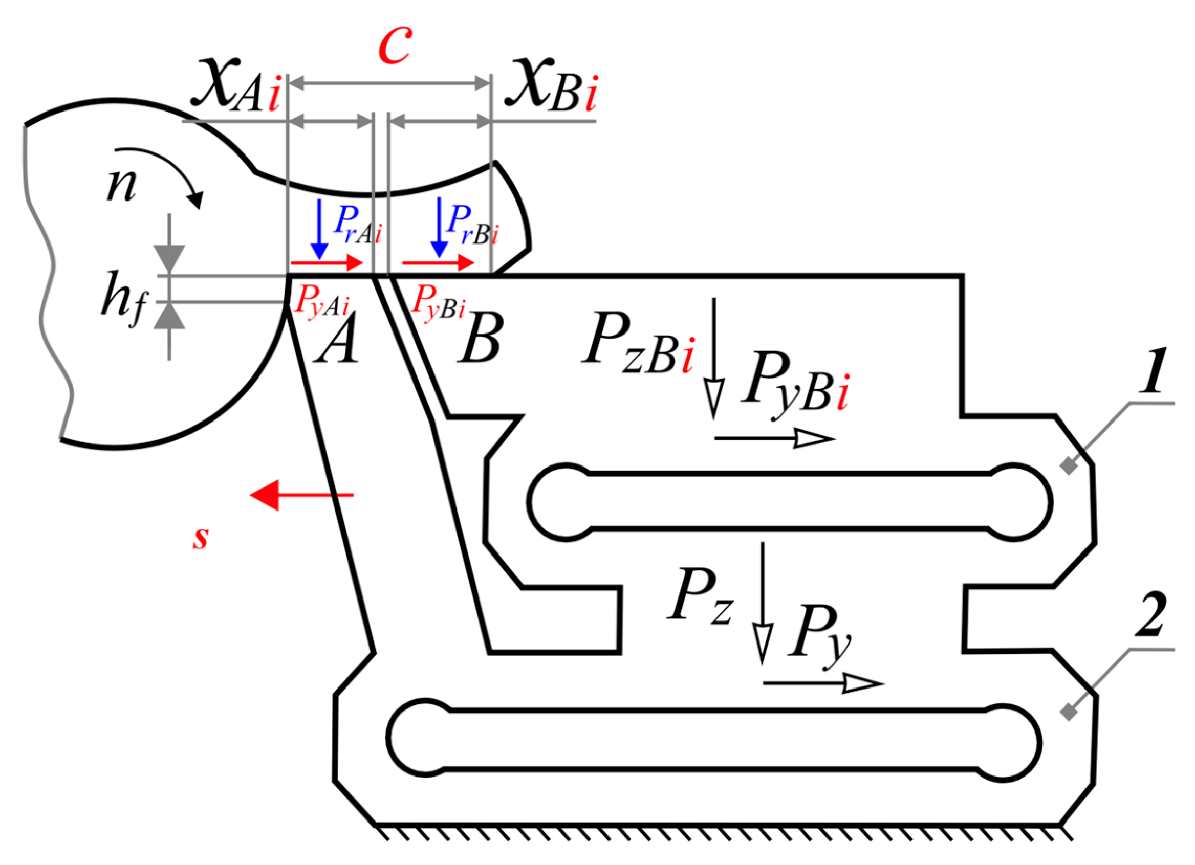
The method of a “section tool” (or split cutter method) is used for research of contact stress distribution (Figure 3 and Figure 4) [33,34,35,36]. It is very labor consuming, demands the use of a rigid special four-component dynamometer, and in cutting difficult-to-machine material, chipping and breakage of cutting plates occur, which causes the repetition of all series of experiments. Therefore, we carried out research on the calculation of epures parameters of contact stresses, which use the measured or calculated technological components of cutting force.

2. Materials and Methods

The study of the contact stresses distribution was performed when turning a workpiece made of steel (Fe-0.4 C-1 Cr, or steel 5140 in accordance to ASTM-SAE) with hardness HB 180 and ultimate tensile stress σUTS = 495 MPa by two different methods:
  • First, using the split cutter method (Figure 3 and Figure 4) to determine the distribution (epure, plots) of contact stresses on the rake (front) surface of the cutter, followed by the determination of the parameters of the characteristic (reference) points of the contact stress plots (epure). This will make it possible to plot the normal σ and shear (tangential) τ contact stresses (MPa) according to the normal N and shear (tangential) F physical components of the cutting force Pr (N) on the rake surface. These forces can be calculated by knowing the measured technological components Pz r and Pxy r of the cutting force and the magnitude of the rake angle γ. The use of the split cutter method also makes it possible to determine the distribution (epure, plots) of normal σh and shear (tangential) τh contact stresses (MPa) on the wear chamfer on the side-relief (rear) surface (on the flank-land surface);
  • With the measurement of the technological components Pz r and Pxy r of the cutting force on the rake surface of the cutter during longitudinal turning of the workpiece with a conventional turning cutter, followed by the calculation of the normal N and shear (tangential) F of the physical components of the cutting force Pr on the rake surface. Based on these physical components of the cutting force on the rake surface, distribution (epure, plots) of normal σ and shear (tangential) τ contact stresses on the rake surface were constructed, taking into account the regularity (rules) that were obtained by the split cutter method.
Since measuring the technological components of the cutting force using a conventional three-component turning dynamometer is less laborious compared to using a special four-component dynamometer for the split cutter method [1], measurements were performed with a large number of experiments with different cutting modes and the rake angle of the turning cutter.
This made it possible to identify the influence of the above conditions on the magnitude of the main parameters of the contact stress plots, according to which it is possible to construct plots for the studied conditions without performing experiments.
When performing experiments using the split cutter method, a special dynamometer designed by research teams led by Kozlov V.N and Mohsen Marani [30,31] was used, having two levels (frames) of elastic measuring elements 1 and 2 (Figure 3), which allows controlling the constancy of the common technological components Pz and Py of the cutting force, regardless of length the chip section xBi, which is in contact with the main measuring plate B.
The cutting of the periphery of the disk made from the have being machined material was carried out with a radial feed rate of the cutter f = frad, T, i.e., with orthogonal (rectangular) free cutting, therefore the uncut chip thickness a (mm) is equal to the feed rate frad (mm/rev).
Plates with a width of 120 mm have several sections in which the different distance xAi (mm) from the cutting edge to the surface separates the plates (Figure 4). In the manufacture of plates, the largest distance xAi max is slightly longer than the chip contact length with the rake surface of the cutter c (mm), which corresponds to the material being machined, rake angle, and the selected cutting mode: feed rate f (mm/rpm) and cutting speed v (m/min).
The disk to be machined had a diameter ddisk = 250…180 mm (Figure 5) is pre-prepared for the experiment: it is machined on the peripheral part for a short length of 15–20 mm from the periphery on diameter and with width b = 4 mm to increase the rigidity of its working part and reduce its broadening in contact with the cutting edge of the cutter. The width of the uncut chip b (mm) was assumed to be equal to the width of the disk bd (mm) due to a slight broadening of the chips during cutting.
When the contact area of the cutting edge with the disc changes, i.e., when the cutter periodically moves along the axis of rotation of the disc, the distance xAi changes (Figure 3 and Figure 4), but the sum of the length of the chip contact with the rake surface of the plate A (xAi) and plate B (xBi) remains unchanged: xAi + xBi = c.
The calculation of the physical components of the cutting force N and F according to the technological components Pz and Py when the rake (front) angle γ ≠ 0° is performed according to the formulas that were obtained from the sum of the vectors (Figure 5):
P z = N P z + F P z ;             P y = F P y + N P y .
From these formulas, when γ > 0°, we obtain Equations (1) and (2) for calculating the physical cutting forces:
N = NPzNPy = Pz × cos γ − Py × sin γ,
F = FPy + FPz = Py × cos γ + Pz × sin γ
In Equation (1), the second term has a minus sign (−NPy) since this component is directed in the opposite direction compared to the direction of the NPz vector. This creates a paradoxical situation: with an increase in the rake angle γ with an increase in the technological force Py, the normal physical force N in Equation (1) decreases, which at very large rake angles (more than 25°) can lead to a small normal force N if the second part of Formula (1) is only slightly less than the first part, i.e., the average conditional coefficient of friction µaverage = F/N will increase with an increase in the rake angle γ.
With a negative value of the rake angle γ and non-free cutting, slightly different equations are used:
N = NPz + NPxy = Pz × cos γ + Pxy × sin γ,
F = FPxyFPz = Pxy × cos γ − Pz × sin γ.
where Pxy = (Px2 + Py2)0.5.
The increment of the forces Py and Pz on the considered i-th section of the plate in comparison with these forces on the previous (i − 1) section are calculated by the equations:
PyBi = Py B i − ∆Py B i−1 (H).
Pz B i = Pz B iPz B i−1 (H).
The normal Ni and shear (tangential) Fi forces acting on the i-th section are calculated according to Equations (7) and (8) in accordance with Equations (1), (2), (5) and (6):
Ni =Pz B I × cos γ −PyBi × sin γ,
Fi =PyBi × cos γ +Pz B I × sin γ.
The specific normal qN i and shear (tangential) qF i contact loads (forces) on the i-th section of plate B are calculated as the ratio of the increment of forces on this section to the increment of the chip contact area ∆Si on this i-th section:
qN i = ∆Ni/∆Si = (NiNi−1)/(∆xi × b)   (MPa);
qF i =Fi/Si = (Fi − Fi−1)/(∆xi × b)   (MPa)
At ∆xi → 0 mm, the specific normal qN i and shear (tangential) qF i contact loads on the i-th section of plate B will approach the normal σ and shear (tangential) τ contact stresses in this section: qN i ≈ σi (MPa), qF i ≈ τi (MPa).

3. Results and Discussion

3.1. Investigation of the Contact Stresses Distribution on the Rake Surface by the Method of a Split Cutter

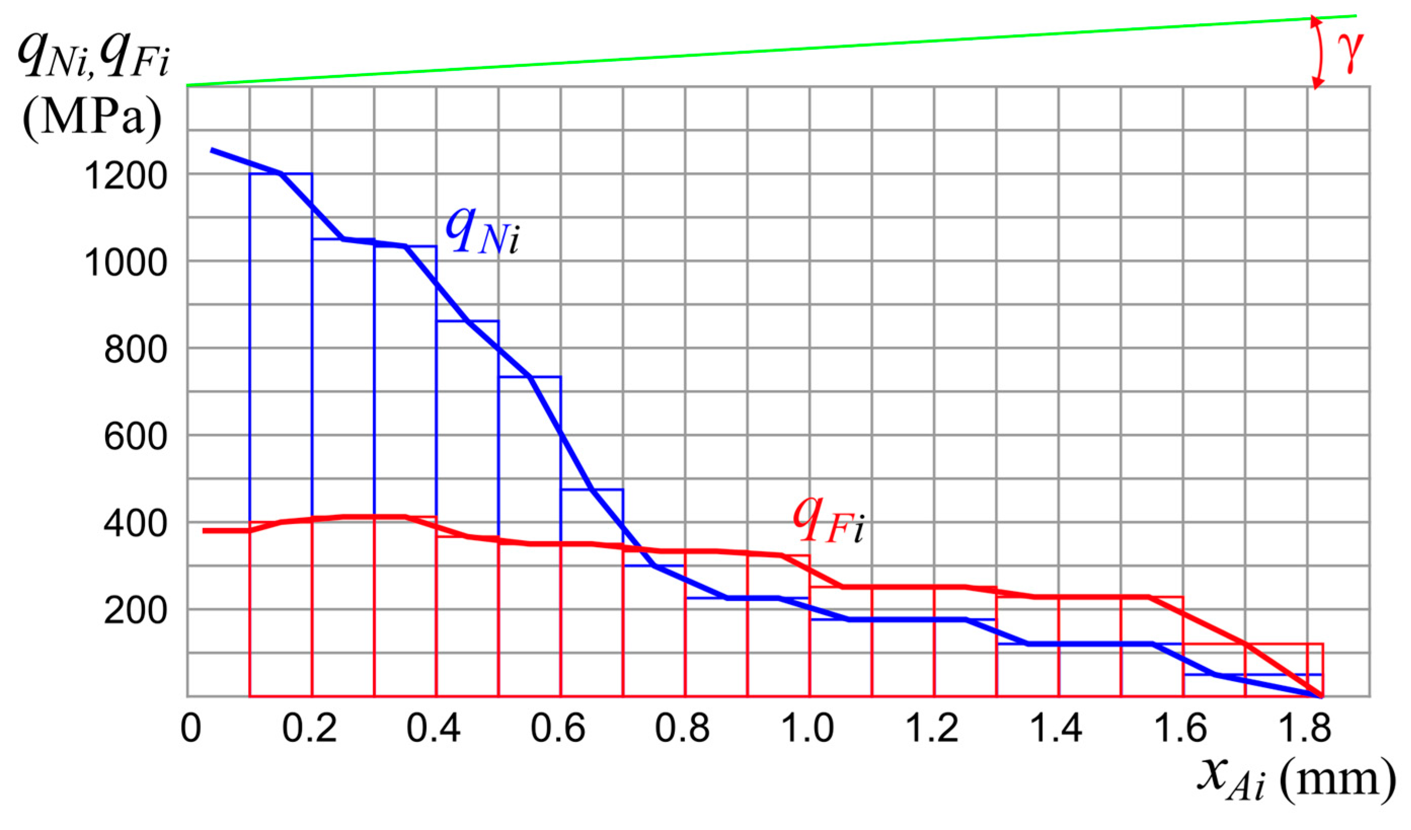
Figure 6 shows histograms of specific normal qNi and shear (tangential) qFi contact loads on various parts of the rake surface of the cutter, which can be used to plot the distribution (epures, plots) of normal σ and shear (tangential) τ contact stresses.
Plotting is better to start with a plot of shear τ contact stresses because, in Figure 6, it is possible to distinguish a section from xAi = 0 mm to xAi = c1 = 0.992 mm (i.e., c1 ≈ 0.5 × c), where the distribution of τ is uniform, i.e., in this section, the graph of τ is parallel to the rake surface of the cutter, this corresponds to numerous investigations of contact loads during steel machining [1,2,3,4]. This will allow you to calculate the magnitude of shear contact stresses τ in this area, knowing the magnitude of the shear force F:
τconst = F/(0.75∙c∙b).
where c is the length of the chip contact with the rake surface (see Figure 2).
In our example, τconst = F/(0.75∙cb) = 2014/(0.75∙1.844∙4) = 364.9 (N/mm2). This value corresponds to the average value of shear contact stresses in this area (τi varies from 343 to 400 MPa).
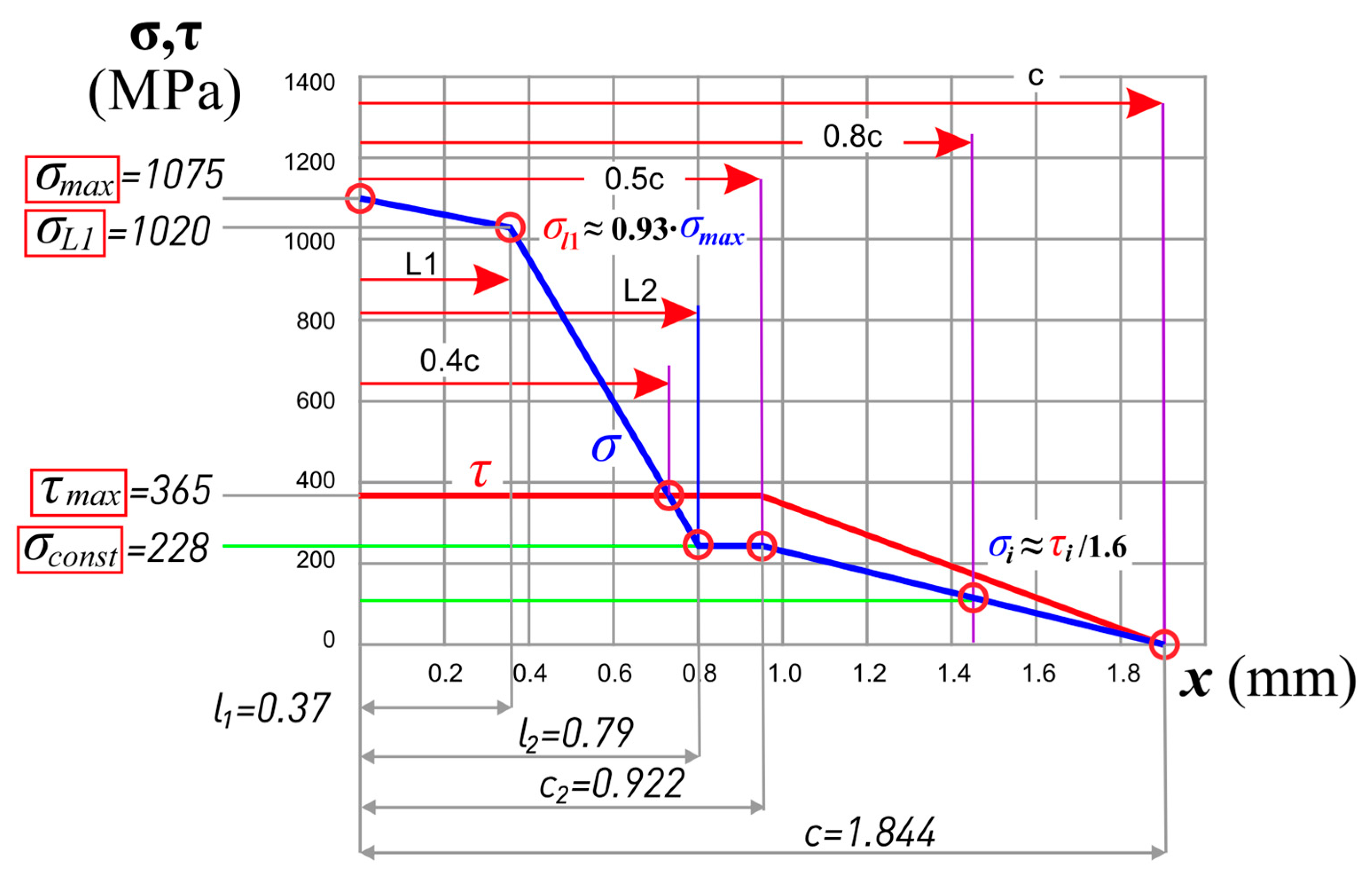
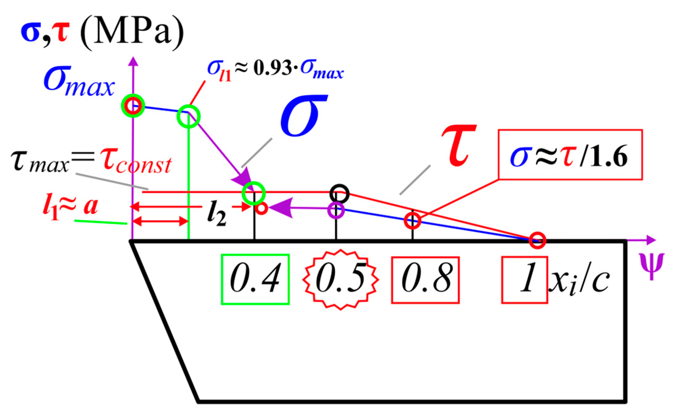
Simplified diagrams of contact stresses are shown in Figure 7. They are also marked with characteristic (reference) points that allow you to draw these diagrams.
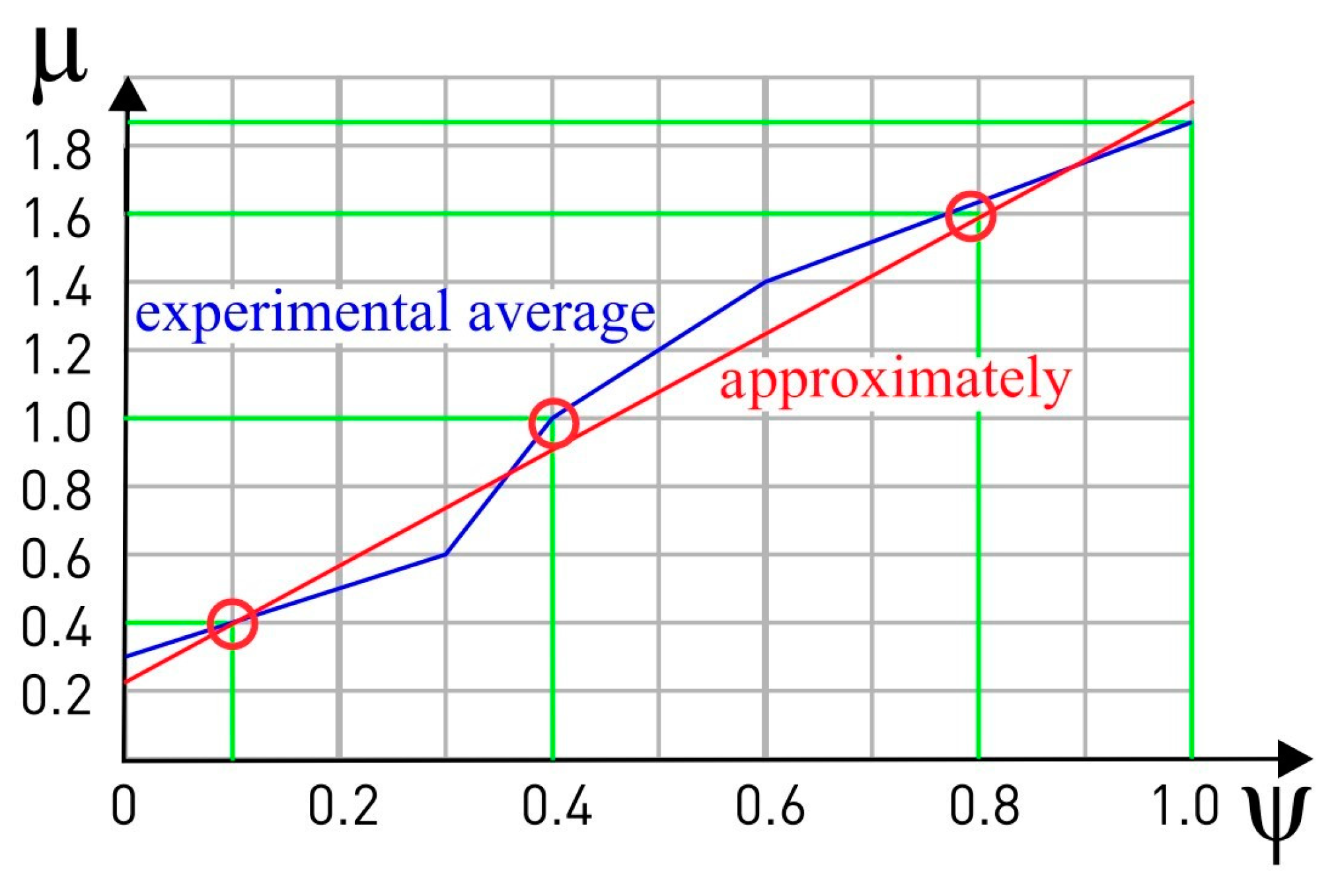
The shape of the diagram of normal contact stresses σ is much more complicated; therefore, we proposed to construct it relative to the diagram of shear contact stresses τ, knowing the change in the conditional coefficient of friction µi = τii along the rake surface of the cutting tool [33] (Figure 8 and Figure 9).
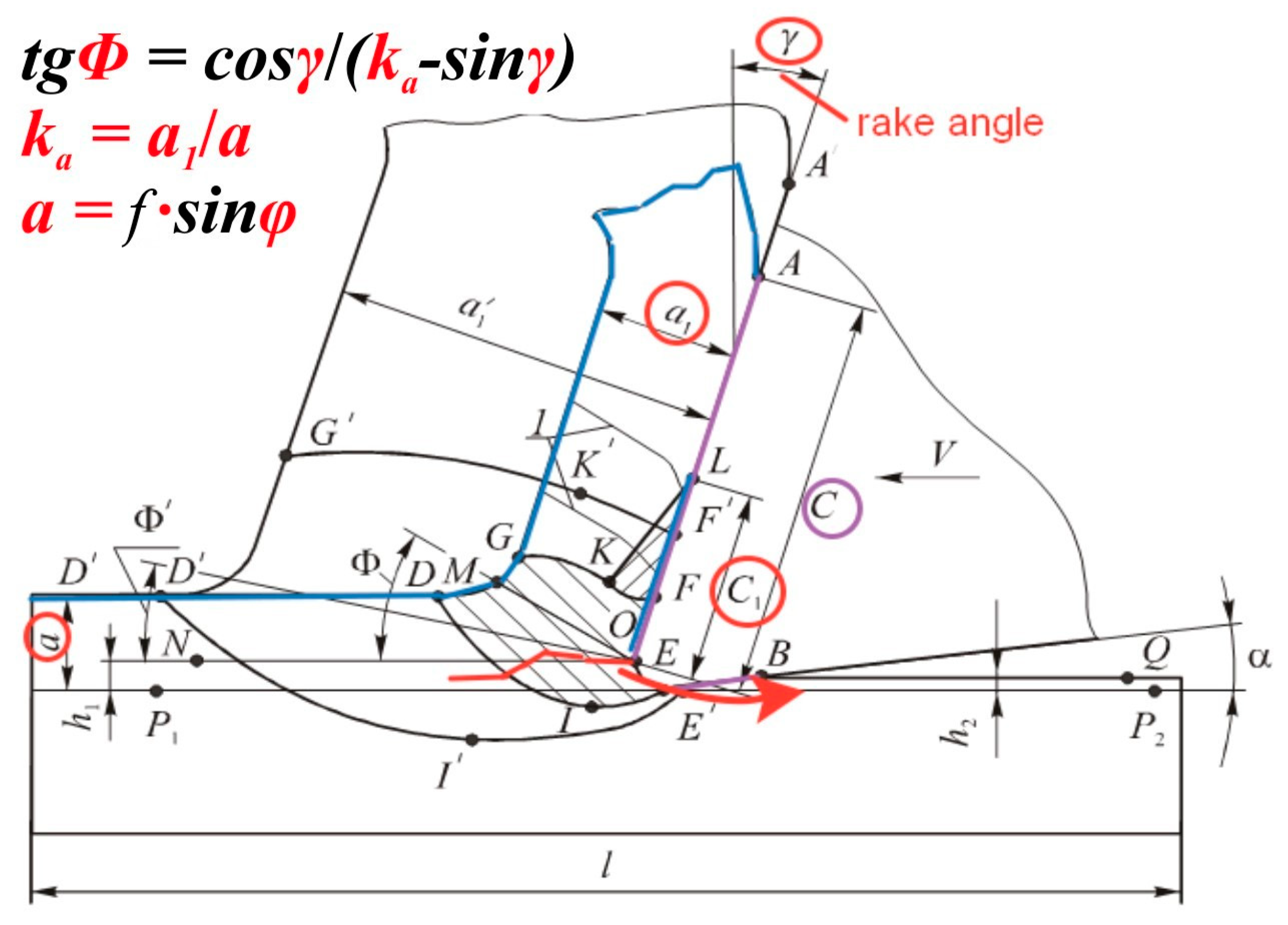
The results of numerous experiments by various researchers have shown that the regularities of the change in the µi depend little on the rake angle and the uncut chip thickness a = s∙sinφ, where φ is the principal edge angle in the plan φ (°) (see Figure 1 and Figure 2). When analyzing the experimental results, the relative coordinate ψi = xi/c (dimensionless value) is often used, where xi is the distance of the point from the cutting edge of the tool.
This allows you to indicate on one graph c = f(ψi) the changes of µ at different values of the uncut chip thickness a and other cutting conditions, i.e., generalize the results of different experiments in which different chip contact lengths c were obtained.
At the relative coordinate ψi = xi/c ≈ 0.4, i.e., at xi = 0.4·c, there will be an intersection of the graph σ with the graph τ, because at this point, the coefficient of friction μi = 1, that is, there σ = τ (Figure 7, Figure 8 and Figure 9).
At the end of the chip contact with the rake surface of the cutter at the point ψi ≈ 0.8 (i.e., at xi ≈ 0.8·c), there should be σi≈ ti/1.6 (Figure 7, Figure 8 and Figure 9).
Through two points: number 1—at xi = c, where σi = 0 MPa; and number 2 at xi = 0.8·c, where σi ≈ τi/1.6—we draw a straight line to the intersection of the inclined part of the graph σ with the line perpendicular to the rake surface at point xi = 0.5·c (Figure 7 and Figure 10).
From the obtained point, we draw a straight line parallel to the rake surface toward the cutting edge to the intersection with the inclined straight line σ falling from the cutting edge (Figure 7 and Figure 10) because, in the section up to xi ≈ 0.5∙c, there is a horizontal line at the plot of normal contact stresses σ.
The value of σmax at the cutting edge is first set approximately by ourselves. In the first approximation, σmax = 2∙UTS, where UTS is the ultimate tensile stress of the material being machined at room temperature (MPa). For example, for steel (Fe-0.4 C-1Cr), UTS = 495 MPa.
At a distance from the cutting edge l1a (mm) σl1 ≈ (0.92…0.93)∙σmax, because there are no chips there yet, it is just being formed, the pressure from the cutter goes to the workpiece (see Figure 11), so there is an approximately uniform distribution of normal stresses σ.
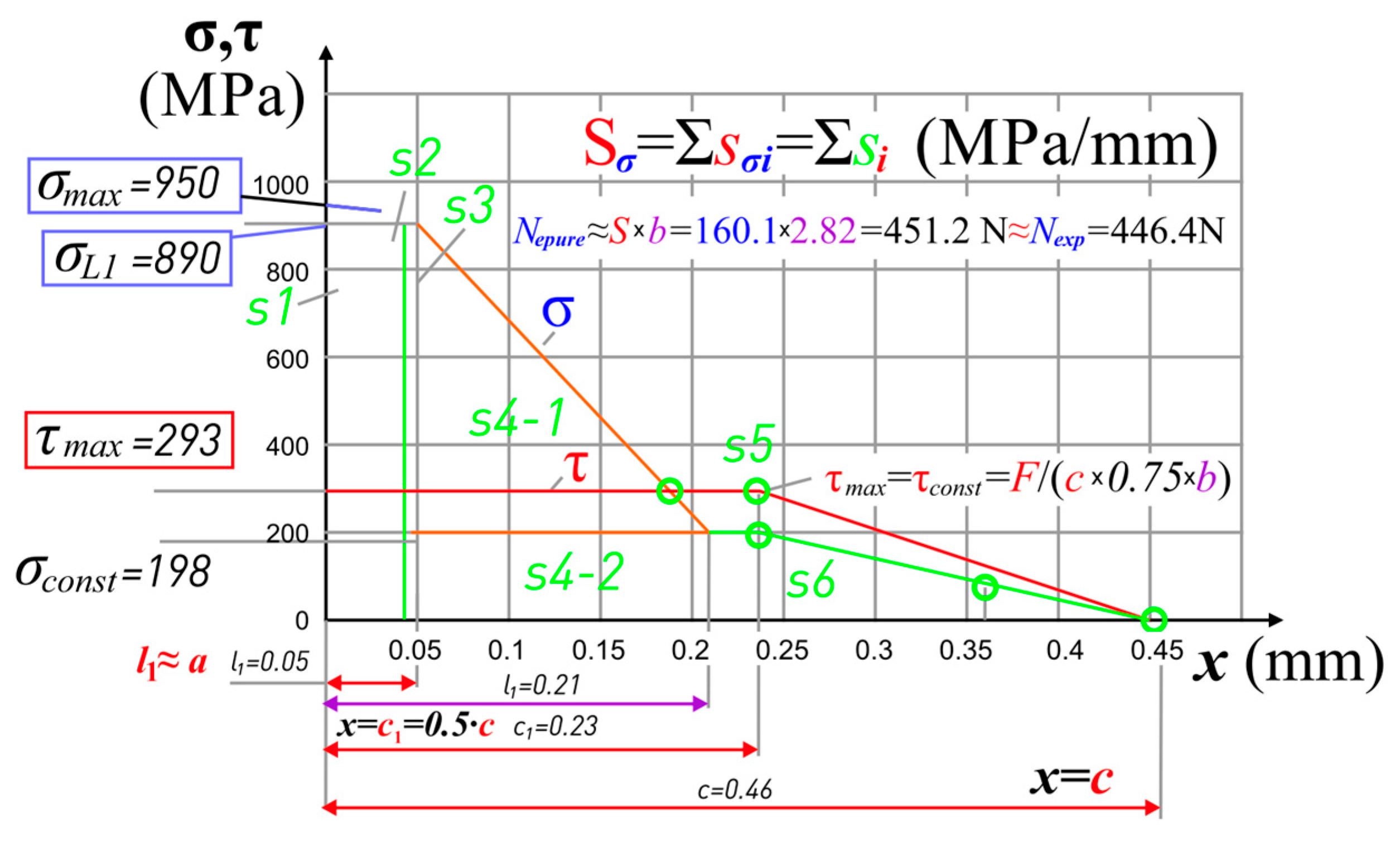
We check the correctness of plotting—the force calculated by the area (volume) of the plot should be approximately equal to the corresponding force from the experiment.
We correct the correctness of the assignment of σmax so that equality is observed
N σ = b   ×   0 c σ i × d x N exp ( N ) ,
where x varies from 0 (the coordinate at the cutting edge, i.e., at x = 0 mm) to x = c (the coordinate of the chip separation point from the rake surface); b is the width of the chip contact with the rake surface of the cutter, for oblique cutting b = t/sin φ.
To fulfill equality (12), the area of the plot σ (Sσ) is calculated first (see the example in Figure 12): Sσ = Σsσi (MPa/mm).
Then, the normal force is calculated from the plot σ: Nσ = Sσb (N). It should be approximately equal to the normal force according to the experiment Nexp (N).
If the normal force according to the plot σ, i.e., Nσ, is less than the one obtained in the experiment Nexp, then we increase σmax; if more, then we decrease it. After that, we recalculate the normal force according to the plot Nσ and repeat until we get NσNexp.
Similarly, we perform for the shear force according to the plot τ: Fτ =SτbFexp (N).
But, there should not be any problems here because initially τconst = F/(0.75∙cb).
Finding the value of σmax by the above method is the only possible way to determine it because no currently known method can determine contact stresses closer than 0.1–0.2 mm from the cutting edge because the plates A and B of the split cutter (Figure 3) are being chipped if the distance from the cutting edge to the separation surface of the plates xAi ≤ 0.2 mm, and when using laser interferometry methods [3,31,32] or polarization-optical [1], the lines (strips) of isocline or isochrome merge and it is impossible to distinguish them.

3.2. Determination of the Main Parameters of the Plots Using a Kistler Dynamometer

The technological components Pz, Px, and Py of the cutting force (see Figure 1) were measured during longitudinal turning of a workpiece made from steel 40× with a conventional turning cutter mounted on a three-component Kistler turning dynamometer.
Cutting was carried out with a different feed rate f = 0.07…0.52 (mm/rev) at a cutting speed v = 120 m/min, which excluded the appearance of a built-up end (growth) on the rake surface of the cutter. The magnitude of the side-rake angle γ varied from +40 to −10°.
After cutting, the total chip contact length c (mm) and the length of the plastic chip contact c1 (mm) with the rake surface were measured using an instrumental portable microscope (Figure 2 and Figure 12). Graphs of the effect of the uncut chip thickness a and the rake angle γ on the total chip contact length c, which is necessary for plotting contact stresses, were constructed (Figure 13).
A chamfer with a length hf = 0.95 mm with the clearance (flank, rear, side-relief) angle αh = 0° was sharpened on the side-relief (rear, flank, back) surface to study the effects of wear on the technological components of the cutting force. It simulated wear on the side-relief surface. After carrying out a series of experiments with different feed rates f, the cutter was re-sharpened only along the side-relief surface with a side-relief (rear, clearance) angle α = 12°, which ensured a constant side-relief angle on the chamfer αh = 0° when the length of the chamfer hf was varied from 0.95 mm to zero, i.e., to a sharp cutter.
By extrapolating the components Pz, Px, and Py of the cutting force to the zero wear chamfer, forces acting only on the rake surface of Pz r, Px r, and Py r were isolated. The resulting component P x y r = P x r 2 + P y 2 r , acting in the reference (main) plane, was calculated. These components, Pxy r and Pz r, were used to calculate the normal N and shear F of the physical components of the cutting force on the rake surface according to Equations (3) and (4) with a negative value of the rake angle γ, and with a positive value of the rake angle γ, Equations (13) and (14) were used:
N = NPz − NPxy = Pz r × cos γ − Pxy r × sin γ,
F = FPxy + FPz = Pxy r × cos γ + Pz r × sin γ.
Based on these physical components N and F of the cutting force, plots of normal σ and shear τ contact stresses on the rake surface were constructed, taking into account the regularities (patterns) that were obtained by the split cutter method. On each graph of the distribution of contact stresses, the values of the main parameters of the plots (reference points) were determined (Figure 10), after which graphs of the effect of the uncut chip thickness a = f∙sinφ (mm) and the rake angle γ (°) (cutting conditions) on the value of the main parameters of the plots of contact stresses on the rake (front) surface were plotted in turning of steel 40× (Figure 10 and Figure 12,Figure 13,Figure 14). A large number of points on the graphs allows us to confidently assert the reliability of the obtained graphs.
The greatest interest is the graphs of the effect of the uncut chip thickness a and the rake angle γ on the largest normal contact stress σmax on the rake surface (Figure 14) since this value determines the load on the rake surface of an unworn out cutting tool.
It can be seen from the graphs in Figure 14 that a decrease in the rake angle γ from +35 to −10° leads to a significant increase in σmax from 400 to 1400 N with the uncut chip thickness a = 0.368 mm. When the uncut chip thickness a decreases in the range from 0.368 to 0.17 mm, the value of σmax decreases, which also does not cause contradictions with existing ideas about contact processes on the rake surface.
With the uncut chip thickness a less than 0.17 mm, σmax begins to decrease intensively at γ = −10°, but on the contrary, it increases at γ = +35°, +25° and +15°.
In our opinion, the intensive decrease in σmax at γ = −10° and the small uncut chip thickness (a < 0.15 mm) is associated with the appearance of a small build-up edge (growth) on the rake surface and an increase in the actual the rake angle γ [1]. With a large uncut chip thickness a, this effect is not so significant.
The second factor contributing to a decrease in σmax at γ = −10 ° and a < 0.15 mm is associated with an increase in the deflection (sag) of the transient (cutting) surface [5], which leads to a decrease in pressure on the rounded section of the cutting edge due to the redistribution of the normal load on the rest of the chip contact with the rake surface.
Therefore, the paradoxical intensive increase in σmax at γ = +35 ° and a small uncut chip thickness a < 0.17 mm is also associated, in our opinion, with the deterioration of conditions for the formation of a small build-up edge with γ > +25 ° the probability of the appearance of the build-up edge (growth) decreases sharply [1]. The appearance of the build-up edge causes an increase in the actual rake angle γactual, and this leads to a decrease in the cutting force [1].
The presence of a small build-up edge is especially important when machining with a small uncut chip thickness a, because the build-up edge prevents the indentation (pressing) of the material being machined under the cutting edge (see Figure 11) [1,2], which means it prevents a significant increase in forces on the radius section of the rounded cutting edge: even with a sharpened cutter, the radius of rounding of the cutting edge is ρ ≈ 0.002–0.005 mm.
With a small chip thickness (a < 0.17 mm), the indentation (pressing) of the material being machined under the cutting edge in the chip formation zone increases [1]. This leads to an increase in the components of the cutting force Pz ρ, Py ρ, and Px ρ on a rounded section of the cutting edge, but in the absence of a wear chamfer on the flank surface, this is perceived as forces on a flat area of the rake surface.
The increase in σmax at γ = +15° and a small value of the uncut chip thickness (a < 0.1 mm) is similar to the changes at γ = +35° but begins a little later with a decrease in the uncut chip thickness due to a smaller rake angle. A similar effect should be at γ = +25° with a decrease in the uncut chip thickness a < 0.14 mm; however, a not very intense increase in σmax compared to γ = +15° is unclear and can only be explained by us as an error in measuring forces at a = 0.05 mm with the rake angle γ = +25°.
Special attention should also be paid to the effect of the uncut chip thickness a on the value of the greatest shear contact stress τmax = τconst (Figure 15). These graphs confirm the statements of various researchers about the small effect of the uncut chip thickness a and the rake angle γ on its magnitude [1]. Only when the rake (front) angle γ = −10° is negative does the graph τmax = f(a) differ from the others.
The value of the greatest shear stress τmax = τconst varies slightly (τmax = 350–400 MPa) in the range of the uncut chip thickness a = 0.37–0.07 mm and the rake angle γ = +35–0°, but the greater the rake angle γ, the greater the value of the τmax. At γ = +7°, the value of τmax does not change, which allowed scientists to assert that the cutting mode does not affect the value of the shear stress τ on the first half of the chip contact length.
Increase in τmax at a small value of the uncut chip thickness a < 0.07 mm for γ = +35 … +15° is explained by us as the effect of indentation (pressing) of the being machined material under the cutting edge in the chip formation zone, what causes an increase in forces not on a flat area of the rake surface, but on the rounded section of the cutting edge: the larger the rake angle, the more intensively the τmax increases in this area with a decrease in the uncut chip thickness a < 0.07 mm.
The special character of the graph τmax = f(a) at γ = −10° is explained by us as the influence of a seizure (stagnant) zone or a build-up edge: at a negative rake angle, the velocity vector of the have being formed chips changes its direction, which creates more favorable conditions for the formation of a seizure (stagnant) zone. With a decrease in the uncut chip thickness a < 0.37 mm, even its small value more significantly changes the friction force on the contact surface at the cutting edge.
With a further decrease in the uncut chip thickness (a < 0.17 mm), an increase in τmax occurs due to an increase in forces not on a flat area of the rake surface but on the rounded section of the cutting edge due to the indentation (pressing) of the have being machined material under the cutting edge in the chip formation zone, which occurs to a greater extent with a negative rake angle.

4. Conclusions

  • The characteristic (reference) points on the graphs of normal σ and tangential τ contact stresses, which are necessary for constructing these graphs during steel processing (Fe-0.4 C-1Cr), are determined.
  • The effect of the uncut chip thickness and the rake angle on the length of the chip contact with the rake surface was revealed during the machining 40× steel. Graphs were constructed, and equations were obtained for calculating the chip contact length.
  • When plotting contact stresses on the rake surface of the cutting tool, it is necessary to start with plotting the shear contact stresses since it has a simpler shape, which allows using the proposed simple formula to determine its main parameter.
  • The shape of the diagram (diagrams) of normal contact stresses is much more complicated, so we proposed to construct it relative to the diagram of shear contact stresses, knowing the change in the conditional coefficient of friction along the rake surface of the cutting tool perpendicular to the cutting edge.
  • The results of numerous experiments by different researchers have shown that the regularities of the change in the conditional coefficient of friction along the rake surface depend little on the rake angle and the uncut chip thickness. When analyzing the experimental results, the relative coordinate was used.
  • After plotting the contact stresses epures, it is necessary to check the correctness of their construction—the force calculated by the volume of the plot should be approximately equal to the corresponding force from the experiment.
  • The values of its reference points (σmax, σconst, L2, τmax) were determined on each plot, after which graphs of the effect of the uncut chip thickness and the rake angle on their value when turning steel 40× were constructed. A large number of points on the graphs allows us to confidently assert the reliability of the obtained graphs.
  • In machining steel (Fe-0.4 C-1Cr), the greatest normal contact stress on a rake surface σmax ≈ varies from 500 to 1100 MPa and depends on uncut chip thickness and rake angle.
  • A decrease in the rake angle from +35 to −10° leads to a significant increase in the greatest normal contact stress from 400 to 1400 MPa for the uncut chip thickness 0.368 mm, which does not cause contradictions with existing ideas about contact processes on the rake surface. It is also natural to decrease σmax the greatest normal contact stress with a decrease in the uncut chip thickness in the range from 0.368 to 0.17 mm.
  • The paradoxical intensive increase in σmax the greatest normal contact stress at rake angle +35–+15° with a decrease in the uncut chip thickness less than 0.17 mm is associated, in our opinion, with an increase in the indentation of being formed material under the cutting edge in the chip formation zone. This leads to an increase in the components of the cutting force P, Pyρ, and P on the rounded section of the cutting edge with radius ρ, but in the absence of a wear chamfer on the flank surface, this is perceived as forces on a flat area of the rake surface.
  • The value of the greatest shear stress varies slightly (350–400 MPa) in the range of the uncut chip thickness 0.37–0.07 mm and the rake angle +35–0°, but the greater the rake angle, the greater the value of the greatest shear stress. At rake angle +7°, the value of τmax, the greatest shear stress, does not change, which allowed scientists to assert that the cutting mode does not affect the value of the shear stress on the first half of the chip contact length.
  • In machining steel (Fe-0.4 C-1Cr), a medium conditional coefficient of friction on a rake surface is large (0.6–0.8). It leads to the occurrence of essential radial force on a rake surface and leads to a sag (deflection) of a transient surface. The presence of the sag of the transient surface leads to a decrease in contact stresses on the wear chamfer on the flank (side-relief) surface near the cutting edge when machining materials form continuous chips.

Author Contributions

Conceptualization, V.K. and A.B.; methodology, A.B. and A.S. (Artem Semenov); validation, V.K. and A.B.; formal analysis, V.K. and A.B.; investigation, V.K., A.B. and N.S.; resources, N.S. and A.S. (Anton Shevchuk); writing—original draft preparation, V.K.; writing—review and editing, A.B., N.S. and A.S. (Artem Semenov); visualization, A.S. (Artem Semenov) and A.S. (Anton Shevchuk); supervision, V.K., A.B. and N.S. All authors have read and agreed to the published version of the manuscript.

Funding

This research was funded by the Russian Science Foundation, project no. 23-79-10166.

Data Availability Statement

The data presented in this study are available upon request from the corresponding author.

Acknowledgments

The research was carried out with the equipment of the Tomsk Regional Core Shared Research Facilities Center of National Research Tomsk State University and using the equipment of the Center for Collective Use “Nanomaterials and Nanotechnologies” of the Tomsk Polytechnic University, for access to which the authors are grateful.

Conflicts of Interest

The authors declare no conflict of interest.

Nomenclature

auncut chip thickness (mm)
a1chip thickness (mm)
Kachip thickness ratio, Ka = a1/a
φthe major cutting edge angle (degree, °)
φ1the minor cutting edge angle (degree, °)
tdepth of cut (mm)
vcutting speed (m/min)
γrake angle (degree, °)
αthe clearance angle—the angle between the flank (or tangent to it) and the cutting edge plane (degree, °)
ctool-chip length (the length of the chip contact with the rake surface) (mm)
c1tool-chip sticking zone length (mm)
l2tool-chip slipping zone length (mm)
ρradius of rounding of the cutting edge (mm)
τshear stress on the rake surface (MPa)
τmaxthe greatest value of the shear stress on the rake surface (MPa)
σmaxthe greatest value of the normal stress on the rake surface (MPa)
σnormal stress on the rake surface (MPa)
μconditional coefficient of friction on the rake surface
ffeed rate (mm/rev)
tdepth of cut (mm)

References

  1. Klocke, F.; Lortz, W.; Trauth, D. Analysis of the dynamic chip formation process in turning. Int. J. Mech. Sci. 2018, 135, 313–324. [Google Scholar] [CrossRef]
  2. Gouarir, A.; Martínez-Arellano, G.; Terrazas, G.; Benardos, P.; Ratchev, S. In-process Tool Wear Prediction System Based on Machine Learning Techniques and Force Analysis. J. Procedia CIRP 2018, 77, 501–504. [Google Scholar] [CrossRef]
  3. Zhao, J.; Liu, Z.; Wang, B.; Hu, J.; Wan, Y. Tool coating effects on cutting temperature during metal cutting processes: Comprehensive review and future research directions. Mech. Syst. Signal Process. 2021, 150, 107302. [Google Scholar] [CrossRef]
  4. Ahmed, T.; Mollick, N.; Mahmud, S.; Ahmad, T. Analysis of Effects of Machining Parameters on Cutting Force Components in Turning AISI 201 Stainless Steel Using Cemented Carbide Cutting Tool Insert. Mater. Today Proc. 2021, 42 Pt 2, 832–837. [Google Scholar] [CrossRef]
  5. Hosseini, A.; Kishawy, H.A. Cutting Tool Materials and Tool Wear. In Machining of Titanium Alloys; Springer: Berlin/Heidelberg, Germany, 2014; pp. 31–56. [Google Scholar] [CrossRef]
  6. Badiger, P.V.; Desai, V.; Ramesh, M.R.; Prajwala, B.K.; Raveendra, K. Cutting Forces, Surface Roughness and Tool Wear Quality Assessment Using ANN and PSO Approach During Machining of MDN431 with TiN/AlN-Coated Cutting Tool. Arab. J. Sci. Eng. 2019, 44, 7465–7477. [Google Scholar] [CrossRef]
  7. Kannan, A.; Mohan, R.; Viswanathan, R.; Sivashankar, N. Experimental investigation on surface roughness, tool wear and cutting force in turning of hybrid (Al7075 + SiC + Gr) metal matrix composites. J. Mater. Res. Technol. 2020, 9, 16529–16540. [Google Scholar] [CrossRef]
  8. Shoba, C.; Ramanaiah, N.; Rao, D.N. Effect of reinforcement on the cutting forces while machining metal matrix composites–An experimental approach. Eng. Sci. Technol. Int. J. 2015, 18, 658–663. [Google Scholar] [CrossRef]
  9. Sujuan, W.; Tao, Z.; Wenping, D.; Zhanwen, S.; To, S. Analytical modeling and prediction of cutting forces in orthogonal turning: A review. Int. J. Adv. Manuf. Technol. 2022, 119, 1407–1434. [Google Scholar] [CrossRef]
  10. Liu, H.; Xu, X.; Zhang, J.; Liu, Z.; He, Y.; Zhao, W.; Liu, Z. The state of the art for numerical simulations of the effect of the microstructure and its evolution in the metal-cutting processes. Int. J. Mach. Tools Manuf. 2022, 177, 103890. [Google Scholar] [CrossRef]
  11. Gok, K. Development of three-dimensional finite element model to calculate the turning processing parameters in turning operations. Measurement 2015, 75, 57–68. [Google Scholar] [CrossRef]
  12. Ghosh, S.; Rao, P.V. Application of sustainable techniques in metal cutting for enhanced machinability: A review. J. Clean. Prod. 2015, 100, 17–34. [Google Scholar] [CrossRef]
  13. Salvatore, F.; Saad, S.; Hamdi, H. Modeling and Simulation of Tool Wear During the Cutting Process. Procedia CIRP 2013, 8, 305–310. [Google Scholar] [CrossRef]
  14. Díaz-Álvarez, J.; Díaz-Álvarez, A.; Miguélez, H.; Cantero, J.L. Finishing Turning of Ni Superalloy Haynes 282. Metals 2018, 8, 843. [Google Scholar] [CrossRef]
  15. Grzesik, W.; Niesłony, P.; Habrat, W.; Sieniawski, J.; Laskowski, P. Investigation of tool wear in the turning of Inconel 718 superalloy in terms of process performance and productivity enhancement. Tribol. Int. 2018, 118, 337–346. [Google Scholar] [CrossRef]
  16. Hoier, P.; Malakizadi, A.; Stuppa, P.; Cedergren, S.; Klement, U. Microstructural characteristics of Alloy 718 and Waspaloy and their influence on flank wear during turning. Wear 2018, 400, 184–193. [Google Scholar] [CrossRef]
  17. Korkmaz, M.E.; Yaşar, N.; Günay, M. Numerical and experimental investigation of cutting forces in turning of Nimonic 80A superalloy. Eng. Sci. Technol. Int. J. 2020, 23, 664–673. [Google Scholar] [CrossRef]
  18. Cascón, I.; Sarasua, J.A. Mechanistic Model for Prediction of Cutting Forces in Turning of Non-axisymmetric Parts. Procedia CIRP 2015, 31, 435–440. [Google Scholar] [CrossRef]
  19. Parihar, R.S.; Sahu, R.K.; Srinivasu, G. Finite Element Analysis of Cutting Forces Generated in Turning Process using Deform 3D Software. Mater. Today Proc. 2017, 4, 8432–8438. [Google Scholar] [CrossRef]
  20. Venkatesh, S.S.; Kumar, T.A.R.; Blalakumhren, A.P.; Saimurugan, M.; Marimuthu, K.P. Finite element simulation and experimental validation of the effect of tool wear on cutting forces in turning operation. Mech. Mech. Eng. 2019, 23, 297–302. [Google Scholar] [CrossRef]
  21. He, Z.; Shi, T.; Xuan, J.; Li, T. Research on tool wear prediction based on temperature signals and deep learning. Wear 2021, 478–479, 203902. [Google Scholar] [CrossRef]
  22. Rmili, W.; Ouahabi, A.; Serra, R.; Leroy, R. An automatic system based on vibratory analysis for cutting tool wear monitoring. Measurement 2016, 77, 117–123. [Google Scholar] [CrossRef]
  23. Rizal, M.; Ghani, J.A.; Nuawi, M.Z.; Haron, C.H.C. Cutting tool wear classification and detection using multi-sensor signals and Mahalanobis-Taguchi System. Wear 2017, 376–377, 1759–1765. [Google Scholar] [CrossRef]
  24. Shen, Y.; Yang, F.; Habibullah, M.S.; Ahmed, J.; Das, A.K.; Zhou, Y.; Ho, C.L. Predicting tool wear size across multi-cutting conditions using advanced machine learning techniques. J. Intell. Manuf. 2021, 32, 1753–1766. [Google Scholar] [CrossRef]
  25. Nouri, M.; Fussell, B.K.; Ziniti, B.L.; Linde, E. Real-time tool wear monitoring in milling using a cutting condition independent method. Int. J. Mach. Tools Manuf. 2015, 89, 1–13. [Google Scholar] [CrossRef]
  26. Chen, S.H.; Luo, Z.R. Study of using cutting chip color to the tool wear prediction. Int. J. Adv. Manuf. Technol. 2020, 109, 823–839. [Google Scholar] [CrossRef]
  27. Dhar, N.R.; Kishore, N.S.; Paul, S.; Chattopadhyay, A.B. The effects of cryogenic cooling on chips and cutting forces in turning AISI 1040 and AISI 4320 steels. Proc. Inst. Mech. Eng. Part B J. Eng. Manuf. 2012, 216, 713–724. [Google Scholar] [CrossRef]
  28. Tulasiramarao, B.; Srinivas, K.; Reddy, P.R.; Raveendra, A.; Kumar, B.R. Finding Cutting Forces While Turning Aperation on Lathe Machine at Different Depth of Cut of Different Metals. Int. J. Innov. Res. Sci. Eng. Technol. 2014, 3, 16866–16872. [Google Scholar] [CrossRef]
  29. Lapshin, V.P.; Turkin, I.A.; Khristoforova, V.V. Assessment of Metal Wear in Turning on the Basis of Components of the Cutting Force. Russ. Eng. Res. 2020, 40, 797–800. [Google Scholar] [CrossRef]
  30. Kumar, R.; Sahoo, A.K.; Mishra, P.C.; Das, R.K. Comparative investigation towards machinability improvement in hard turning using coated and uncoated carbide inserts: Part I experimental investigation. Adv. Manuf. 2018, 6, 52–70. Available online: https://link.springer.com/article/10.1007/s40436-018-0215-z (accessed on 2 November 2023). [CrossRef]
  31. Swain, S.; Panigrahi, I.; Sahoo, A.K.; Panda, A.; Kumar, R. Effect of Tool Vibration on Flank Wear and Surface Roughness During High-Speed Machining of 1040 Steel. J. Fail. Anal. Prev. 2020, 20, 976–994. [Google Scholar] [CrossRef]
  32. Zhuang, K.; Fu, C.; Weng, J.; Hu, C. Cutting edge microgeometries in metal cutting: A review. Int. J. Adv. Manuf. Technol. 2021, 116, 2045–2092. [Google Scholar] [CrossRef]
  33. Satish, G.J.; Gaitonde, V.N.; Kulkarni, V.N. Traditional and non-traditional machining of nickel-based superalloys: A brief review. Mater. Today Proc. 2021, 44 Pt 1, 1448–1454. [Google Scholar] [CrossRef]
  34. Kozlov, V.; Zhang, J.Y.; Guo, Y.B.; Sabavath, S.K. Research of Contact Stresses Distribution on Plunge-Cutting into a Steel Workpiece. Key Eng. Mater. 2018, 769, 284–289. [Google Scholar] [CrossRef]
  35. Marani, M.; Zeinali, M.; Kouam, J.; Songmene, V.; Mechefske, C.K. Prediction of cutting tool wear during a turning process using artificial intelligence techniques. Int. J. Adv. Manuf. Technol. 2020, 111, 505–515. [Google Scholar] [CrossRef]
  36. Szczotkarz, N.; Mrugalski, R.; Maruda, R.W.; Królczyk, G.M.; Legutko, S.; Leksycki, K.; Dębowski, D.; Pruncu, C.I. Cutting tool wear in turning 316L stainless steel in the conditions of minimized lubrication. Tribol. Int. 2021, 156, 106813. [Google Scholar] [CrossRef]
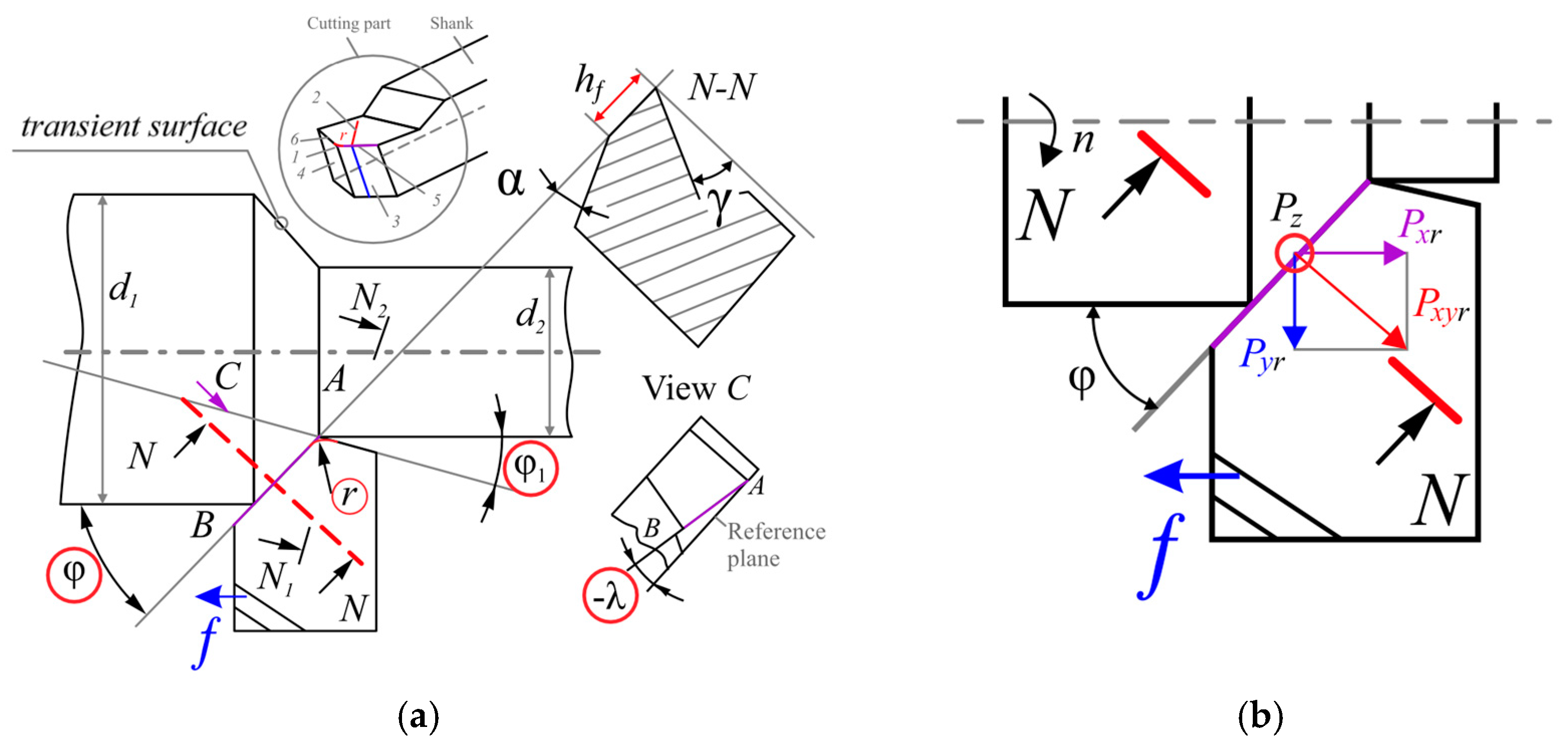
Figure 1. Top view (a) and cross-section of the cutter in the major orthogonal plane N-N (b).
Metals 13 02009 g001
Figure 2. The principal edge angle in the plan φ, the nose radius r, the total contact length c, and the length of plastic contact c1 of a chip with a rake surface of a cutter, instrumental portable microscope.
Metals 13 02009 g002
Figure 3. The position of the plates A and B of the split cutter when the chips come into contact with the main measuring plate B in a section of length xBi and width b.
Metals 13 02009 g003
Figure 4. Sections of the split cutter.
Metals 13 02009 g004
Figure 5. Diagram of the direction of the components of technological Pz, Py and physical NPz, FPz, NPy, FPy cutting forces on the rake (front) surface of the cutter in the major orthogonal plane with rectangular free turning of the periphery of the disk at a positive rake (front) angle γ.
Metals 13 02009 g005
Figure 6. Histograms of specific shear (tangential) qFi and normal qNi contact loads (MPa) on the i-th section on plate B. Abscissa is the distance from the cutting edge xA i (mm). Steel 40× − T15K6, γ = +7°; v = 120 m/min; a = f = 0.368 mm; b = 4 mm; c = 1.844 mm; c1 = 0.922 mm; Py exp = 1623 N; Pz exp = 3061 N; Fexp = 2014 N; Nexp = 2837 N.
Metals 13 02009 g006
Figure 7. Simplified diagrams of normal σ and shear (tangential) τ contact stresses (MPa) on the rake (front) surface of the cutter and reference points for their construction. Steel 40× − T15K6, γ = +7°; v = 120 m/min; a = f = 0.368 mm; b = 4 mm; c = 1.844 mm; c1 = 0.922 mm; Py exp =1623 N; Pz exp= 3061 N; Fexp=2014 N; Nexp =2837 N.
Metals 13 02009 g007
Figure 8. Graphs of changes in the conditional coefficient of friction μi = τii along the chip contact length depending on the relative coordinate ψi = xi/c according to different authors: 1—M.F. Poletika and M.H. Uteshev; 2—G.S. Andreeva and V.M. Zavartseva; 3—V. Katvinkel; 4—H. Takeyama and S. Usui; 5—H. Chandreshekaran and D. Kapoor; 6—V.N. Kozlov (steel 40×—cemented carbide WC + TiC, a = 0.05–0.368 mm, γ = +35°–0°).
Metals 13 02009 g008
Figure 9. The change in the conditional coefficient of chip friction along the front surface µi when machining steel, depending on the relative coordinate ψi = xi/c according to V.N. Kozlov when machining steel 40× with cemented carbide WC + TiC, a = 0.05–0.368 mm, γ = +35°–0°).
Metals 13 02009 g009
Figure 10. The main reference points for plotting plots and their parameters: τconst, σconst = σL2, L2, σmax, σl1.
Metals 13 02009 g010
Figure 11. The processes in the chip formation zone in the major orthogonal plane N-N (see Figure 1).
Metals 13 02009 g011
Figure 12. Checking the correctness of plotting normal σ and shear τ contact stresses on the rake surface of the cutter during oblique cutting. Steel 40× − T15K6; t = 2 mm; v = 120 m/min; γ = 7°, φ = 45°, f = 0.07 mm/rev.
Metals 13 02009 g012
Figure 13. Graphs of the change in the total chip contact length c (mm) with the rake surface of the cutter depending on the side-rake angle γ (°) and the uncut chip thickness a (mm) at φ = 45°.
Metals 13 02009 g013
Figure 14. The effect of the uncut chip thickness a and the rake angle γ on the value of the highest normal contact stress σmax on the rake surface when machining steel 40×.
Metals 13 02009 g014
Figure 15. The effect of the uncut chip thickness a and the rake angle γ on the magnitude of the greatest shear contact stress τmax on the rake surface when machining steel (Fe-0.4 C-1Cr).
Metals 13 02009 g015
Disclaimer/Publisher’s Note: The statements, opinions and data contained in all publications are solely those of the individual author(s) and contributor(s) and not of MDPI and/or the editor(s). MDPI and/or the editor(s) disclaim responsibility for any injury to people or property resulting from any ideas, methods, instructions or products referred to in the content.