Article

Research on the Effect of Pearlite Lamellar Spacing on Rolling Contact Wear Behavior of U75V Rail Steel

1
College of Materials and Metallurgy, Wuhan University of Science and Technology, Wuhan 430081, China
2
Central Research Institue (Qingshan), Baosteel Cooperation, Wuhan 430081, China
*
Author to whom correspondence should be addressed.
Metals 2023, 13(2), 237; https://doi.org/10.3390/met13020237
Submission received: 24 December 2022 / Revised: 17 January 2023 / Accepted: 23 January 2023 / Published: 26 January 2023

Abstract

:
The damage mode of U75V rail steel in application is determined by its rolling wear behavior. In this paper, the pearlite microstructure of U75V steel is characterized to investigate the relationship between wear and fatigue behavior. The results show that, with decreasing of pearlite lamellar spacing, the wear resistance of the steel increases and the contact fatigue resistance decreases. The spacing decreasing causes the change of the wear mechanism from abrasive wear to adhesive wear, as well as the damage mode from wear damage to fatigue damage. The smaller the pearlite lamellar spacing is, the stronger the deformation of the cementite lamellar is. The thin cementite lamellar is hardly broken in the rolling friction to pile up a large number of dislocations in the ferrite matrix and the work hardening degree was improved. So, the plastic deformation layer is difficult to remove, and fatigue cracks are easy to initiate and extend to the interior of the material.

1. Introduction

In recent years, with the increase of train axle weight, speed, and transportation density, the contact stress between wheels and rails has increased, resulting in more and more serious rail damage [1,2,3]. Especially in the small curve radius section, rolling contact fatigue and wear have become the two most important failure modes, endangering the service life and safety of rail traffic [4,5,6,7].
Some studies [8,9,10] show that relative sliding and rolling are detected between the wheels and rails during running of train. Wear and rolling contact fatigue are consistently observed on the rail with cracks in its fatigue zone. Fatigue crack is always affected by rail wear during its initiation and propagation. The fatigue cracks, mainly initiated from the plastic deformation layer on the surface, will be developed into fatigue damage if the layer cannot be worn off in time [11,12]. Various methods, such as simulation calculation [13,14,15], small-scale model test [16,17,18,19], and full-scale test bench test [20,21], have been applied to the study of the relationship between rail fatigue crack and wear. Their main purpose is to find the characteristics of fatigue crack and wear, simulate the relationship between the fatigue crack and wear, or find the control method of fatigue crack and wear of rail. Fletcher [22] observed the balance relationship between crack growth and wear rate using the double-disc rolling test. Donzella [23,24,25] proposed a model to study the competition between wear and surface fatigue crack and used a double-disc rolling test to explore the relationship between wear and crack as well as the relationship between shear strain accumulation and wear under dry and wet adhesive creep contact conditions. W. Zhong [26] presented an analysis of the chemical composition, mechanical performance, and microstructure on U75V and U71Mn rail samples with oblique cracks taken from railway. The strength character of U75V rail is superior to U71Mn rail. The crack propagation angle to the surface of U71Mn rail is smaller than that of U75V rail. Kapoor [27] presented a generic introduction to the concept of interaction between wear and fatigue in the failure of an engineering component. To illustrate the topics discussed, a detailed example is presented of wear–fatigue interaction in the failure of a railway rail.
At present, steel with pearlite microstructure is mainly used as rail. The pearlite lamellar spacing is a key parameter to determine the mechanical performance of the steel, which also affects the service life and traffic safety of rail [28,29,30,31]. The refinement of pearlite is adopted by online heat treatment as spraying air, water mist, or water to improve the strength and hardness of the steel [32,33,34].
However, research has not systematically been reported about the influence law of pearlite lamellar spacing on rolling contact fatigue and wear behavior of rail. Therefore, the influence law of pearlite lamellar spacing on rolling contact fatigue and wear behavior of the rail steel was investigated, the structural changes of different pearlite lamellar spacing in rolling contact friction were observed, the work hardening rates of different pearlite lamellar samples were calculated by microhardness, and the mechanism of pearlite lamellar spacing on wear and fatigue crack was revealed in this paper, which provides a reference basis for the application of rails with different pearlite lamellar spacing.

2. Materials and Methods

The experimental materials are U75V rail steel and wheel steel with the chemical composition as shown in Table 1. The steel was heat-treated by austenitizing at the temperature of 900 °C for 30 min, and then immersed in the salt bath at the temperature of 500 °C, 600 °C, and 650 °C respectively. The isothermal holding time is 10 min at the temperature and the final samples were obtained by air-cooling, the microstructures of which show pearlite with different lamellar spacing (lamellar spacing), the scheme of heat treatment process of rail samples is shown in Figure 1. The lamellar spacing parameters and mechanical properties are shown in Table 2.
Rolling contact fatigue wear test was carried out by rolling wear tester (M2000, ZHENGLI machine, Zhangjiakou, China). The samples for the test are obtained from the two kinds of experiment steels. The sampling position is shown in Figure 2a and the samples are machined into circular rings with the dimensions shown in Figure 2b. The sample of wheel steel is set as the upper sample while the sample of rail steel is set as the lower one.
In order to simulate the contact between the wheels and rails under the actual operating rail conditions, the ratio of the average contact stress between the simulated wheel and rail, and the long and short semi-axes of the ellipse of the contact area under laboratory conditions should be consistent with that in the field. The test parameters are an axial load of 3.2 kN, the spin speed of upper sample is 300 rpm, while the lower one is 270 rpm. The test was performed at room temperature in dry condition. The spin slip rate δ% and the corresponding maximum contact stress σmax are calculated by Equations (1) and (2) [35], respectively.
δ % = W Wheel W Rail W Wheel + W Rail × 200 %
where the WWheel and WRail are the rotation speed of wheel sample and rail sample, respectively. The δ% is 10%
σ m a x = P π L · 1 R Wheel + 1 R Rail 1 v 2 Wheel E Wheel + 1 v 2 Rail E Rail
Contact stress is generated by the rolling contact friction of the ring samples, which belongs to the Hertz stress. Here, the P is the axial load, L is the contact length of the sample, RWheel and RRail are the radius of the wheel sample and rail sample, νWheel and νRail are the Poisson’s ratio of the wheel sample and rail sample, EWheel and ERail are the modulus of elasticity of the wheel sample and rail sample. The calculation result is 1.4 GPa.
The rail sample was measured 9 times at the interval of 2 h from 1st time to 5th, and the 6th and 7th time are at the interval of 4 h. The last two measured times are at an interval of 5 h with the total wear time of 28 h. The mass loss of the samples was measured by electronic analytical balance (AB204-E, Mettler, Zurich, Switzerland). After the rolling contact wear test, the worn surface and plastic deformation layer of the samples were observed by scanning electron microscope (Nova400NanoSEM, FEI, Hillsboro, OR, USA) and optical microscopy (D1M, Zeiss, Oberkochen, Germany). The microhardness of the plastic deformation layer was measured by microhardness tester (HV-1000ZDT, VITRON, Shanghai, China). The microstructure of plastic deformation layer was observed by transmission electron microscope (JEM-2100F, JEOL, Tokyo, Japan). The thin foils were made from the plastic deformation layer, and then mechanically ground to approximately 40-μm thickness. The specimens were further thinned using a twin-jet electro-polisher with an electrolyte consisting of 10 vol% perchloric acid and 90 vol% glacial acetic acid.

3. Experimental Results

3.1. Effect of Pearlite Lamellar Spacing on Wear Performance of Steel

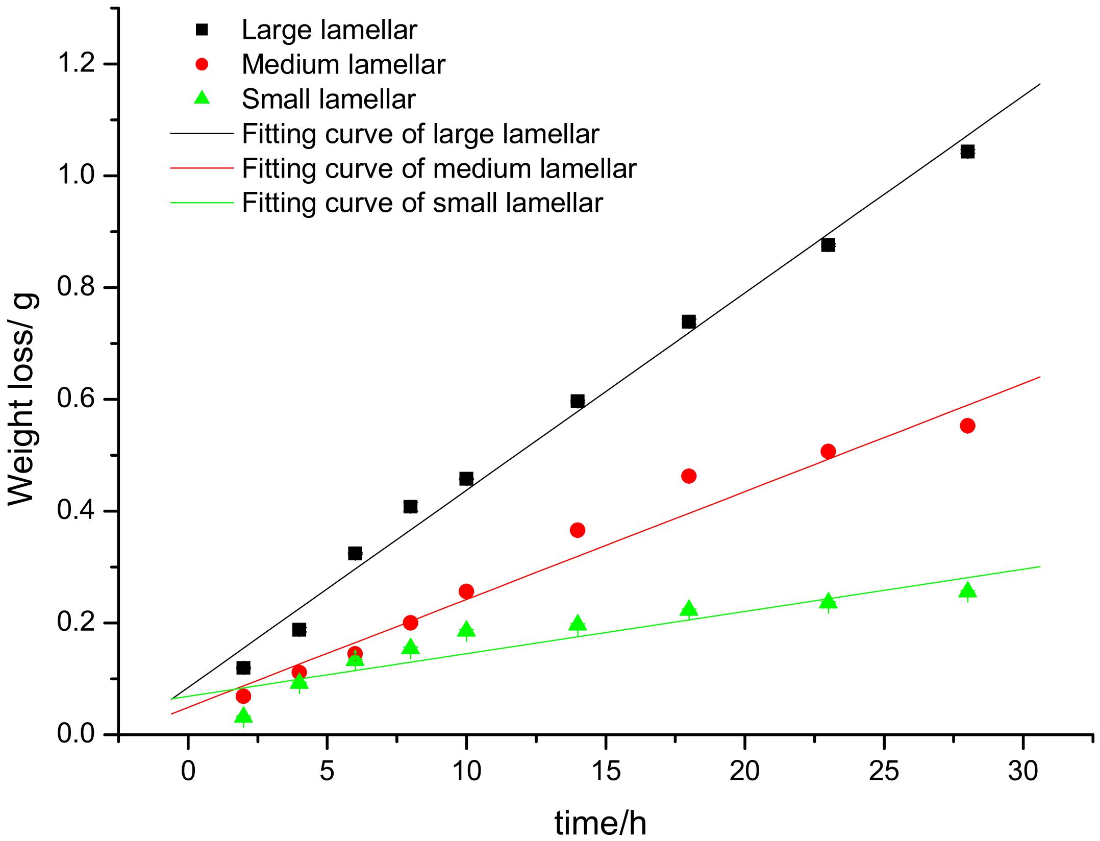
The weight loss and friction coefficient of samples are shown in Table 3 and Table 4. The wear performance of the samples is closely related to pearlite lamellar spacing. Figure 3 shows the weight loss curve of rail samples. The larger the sample of pearlite microstructure with lamellar spacing, the higher the mass loss. Additionally, the mass loss of one with small lamellar spacing is the lowest, which means that the wear resistance of the sample will increase with the decrease of pearlite lamellar spacing.
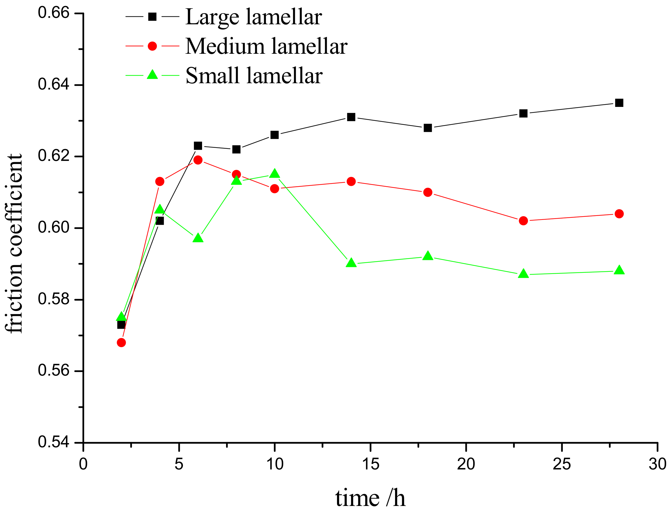
Figure 4 shows the change of friction coefficient of samples during the test. The friction coefficients of the three samples are almost the same in the wear time of less than 2 h. With the increase of wearing time, the friction coefficient of samples increases, which is attributed to the destruction of worn surfaces. The friction coefficient of the sample with large lamellar spacing gradually increases, and that of others with medium and small lamellar spacing remains stable after the samples were worn for 10 h.

3.2. Effect of Pearlite Lamellar Spacing on the Rolling Contact Wear Behavior of Steel

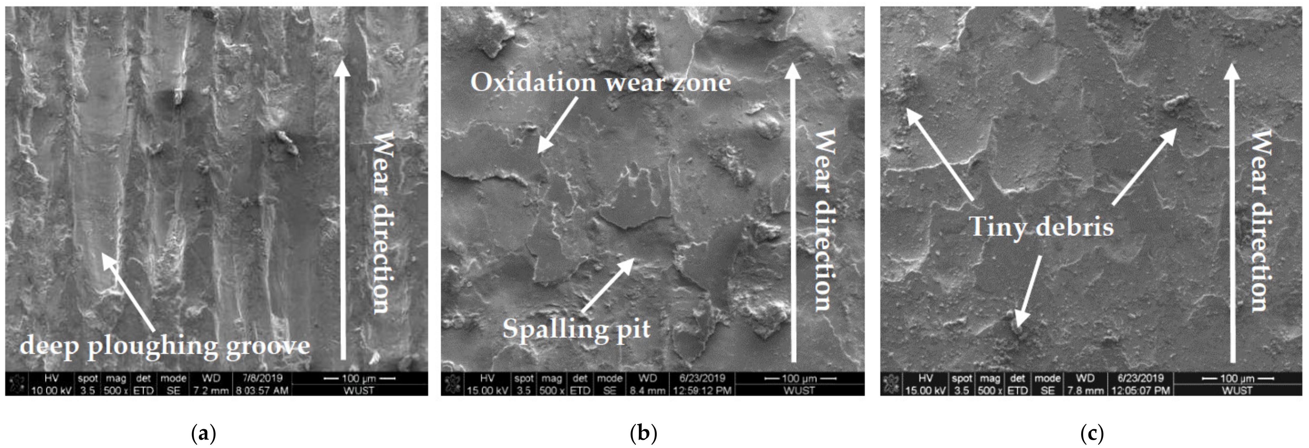
The worn surfaces are significant influenced by the pearlite lamellar spacing of the samples. Figure 5 shows the worn surface morphology of the sample after being worn for 28 h. Obvious deep ploughing grooves along the wear direction are observed on the worn surface of the sample with large lamellar spacing, as shown in Figure 5a. In Figure 5b, little grooves are observed on the sample with medium lamellar spacing, but flaky oxidation wear zones and spalling pits can be seen on the worn surface. The tiny debris are observed on the surface of the sample with small lamellar spacing, as shown in Figure 5c. Otherwise, the oxidation wear zones are obviously increased and a large amount of debris appears on the surface. It can be thought that the sample with small lamellar spacing has the best wear resistance.
Surface plastic deformation can be detected on the cross section of the surface. Besides, the surface is worn during the wear test. Figure 6 is the metallographic photograph of the plastic deformation layer on the surface of the rail sample after being worn for 28 h. The depth of plastic deformation layer of the samples gradually decreases with decreasing pearlite lamellar spacing, which are 200 μm (large spacing), 110 μm (middle spacing), and 55 μm (small spacing), respectively.
During the rolling contact wear test, the maximum contact stress between the wheel and rail is 1.4 GPa, which is greater than the yield strength of the rail samples (about 550 MPa). The plastic flow on the surface of the rail samples will be generated along the rolling direction, which will gradually accumulate below the surface and finally form a plastic deformation layer. The depth of plastic deformation layer decreases with the decreasing lamellar spacing of the sample, which indicates that the sample with small lamellar spacing has a strong ability for deformation resistance.
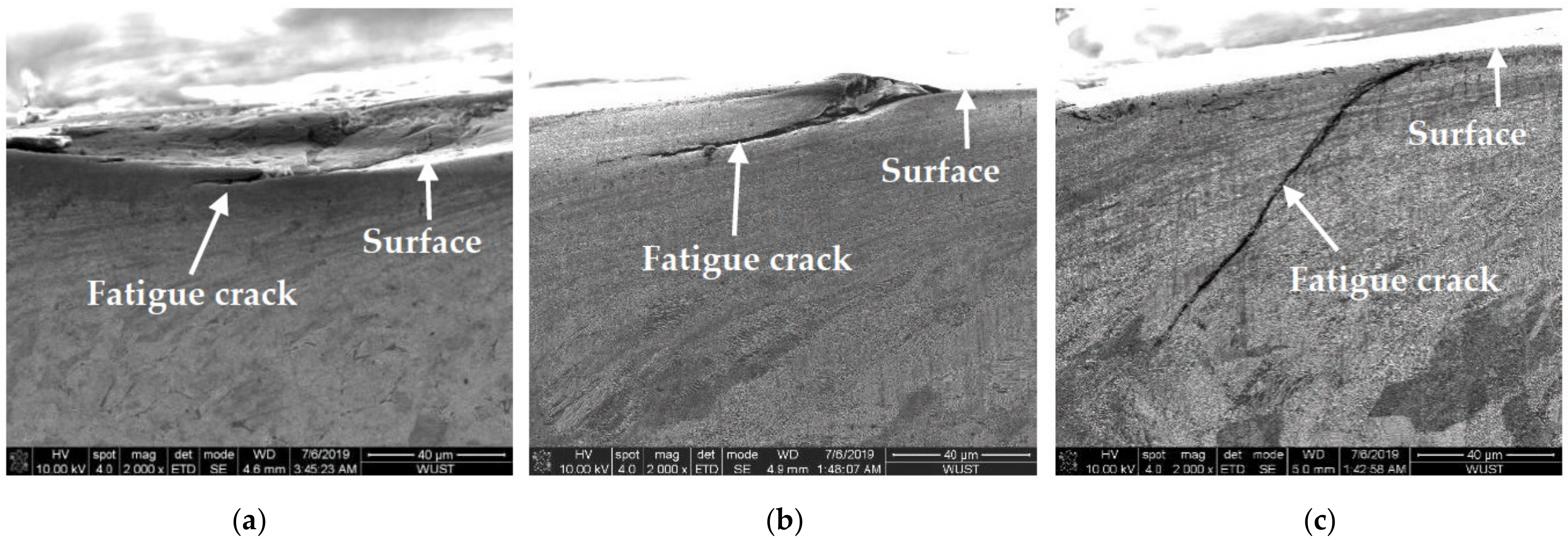
The fatigue performance is also affected by the lamellar spacing. Fatigue cracks can be observed on the vertical section to worn surface of the rail sample, as shown in Figure 7. Its length is decreased with spacing increasing of pearlite lamellar, which is approximately 20 μm for the sample with pearlite microstructure of large lamellar spacing, 80 μm for that with medium lamellar spacing, and 110 μm for that with small lamellar spacing, respectively. The cracks are all initiated from the surface layer and the angle between the crack and the surface is decreasing with the increasing spacing of pearlite lamellar.
Strong work hardening is detected in the deformation layer of the small lamellar sample which has higher susceptibility to cracking. The nucleation of fatigue cracks is quickly produced in the area of high-density dislocations in the plastic deformation. The fatigue cracks can be extended inside the layer for the sample with small lamellar spacing of pearlite microstructure. As the matrix near the cracks is difficultly worn off due to its better wear resistance, the fatigue cracks may further develop into peeling off blocks if the wear time continues to increase.
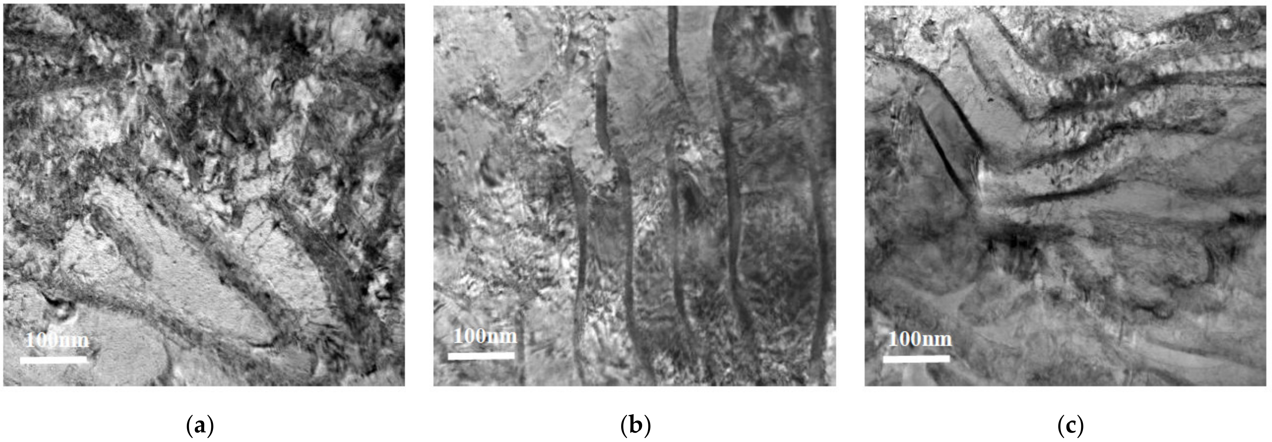
The wear resistance of the steel is affected by the behavior of cementite lamellars. It can be proved, as shown in Figure 8, that the cementite in the pearlite with large lamellar spacing is worn and peeled off, and the one in the pearlite with medium lamellar spacing is partially fractured or peeled off. However, the cementite with the small lamellar spacing is only deformed. The reason for this is as following: The larger the pearlite lamellar spacing is, the more dislocations are accumulated in the ferrite between the cementite lamellars during wearing. The higher stress concentration is caused by the accumulation of dislocations, which induces cementite fracture and spalling. On the contrary, the smaller the cementite lamellar is, the lower the stress concentration is. Moreover, the deformation of thin cementite lamellar can be observed in Figure 8c and the concentrated stress is released by the deformation.

3.3. Effect of Pearlite Lamellar Spacing on Machining Hardening under the Rolling Contact Surface Layer

Table 5 lists the microhardness of the plastic deformation layer and the matrix of the rail sample after being worn for 28 h. The initial hardness of the sample is related to the initial structure of the pearlite lamellae. The initial hardness of the large lamellae sample is the lowest, and that of the small lamellae sample is the highest. The work hardening in the surface layer is evaluated from the data in Table 5, which is produced by a gradual accumulation of plastic deformation in the surface layer of the rail sample. The hardening rate (γ) can be used to measure the work hardening degree and is calculated by Equation (3).
γ = H V 2 - H V 1 H V 1 × 100 %
where HV2 and HV1 are the microhardness of the plastic deformation layer and the matrix in the equation above, respectively. It can be seen in the Table 5 that γ of the sample surface gradually increases as the spacing of pearlite lamellar decreases. Among the samples, the hardening rate of the sample is related to the degree of work hardening. The one with small lamellar spacing has strong work hardening with γ of 35.35%. The strong work hardening and the deformation of thin cementite lamellar can significantly improve the wear resistance of the steel.

4. Analysis and Discussion

The strength and hardness of the steel are determined by cementite lamellar spacing in the pearlite microstructure, which is related to wear resistance [36]. From the mass loss curves in Figure 3, the mass loss and the slope of the curves decrease with decreasing of pearlite lamellar spacing. The inflection point of mass loss curve is approximately 6 h for the sample with small lamellar spacing, and approximately 10 h for the sample with medium lamellar spacing. The earlier appearance of the point means that rolling process of the sample is easier to enter the stable wear stage. The wear mechanism of the sample with large lamellar spacing is mainly abrasive wear to peel off the surface layer of the sample due to its lower hardness (Figure 5a). Then, the surface is ground to roughness, resulting in the increase of the friction coefficient. So, its wear rate is highest. On the contrary, the tiny debris can be observed on the worn surface of the sample with small lamellar spacing, as shown in Figure 5c, which causes the interface contact between upper sample and lower one to transform from two body to three body and keeps the friction coefficient stable.
It is noted from Figure 8 that the cementite lamellars are broken in the deformation layer of some samples. For the pearlite microstructure, the critical shear stress (τe) for the cementite lamellar to be broken under external stress can be characterized by Equation (4) [37].
τ e = [ 4 E γ c / π a ( 1 v 2 ) ] 1 / 2
where γc is the surface energy of the cementite; E the elastic modulus of the cementite; ν its Poisson’s ratio; and a is the thickness of the lamellar. τe is inversely proportional to the square root of the a, so the cementite with the small lamellar spacing is only deformed and the broken cementite lamellars are observed in the samples with pearlite microstructure of large or medium lamellar spacing, as shown in Figure 8a,b. So, the ferrite matrix can not be supported and strengthened by broken cementite in the deformation layer during rolling, and the dislocations can slip in a wider range, resulting in the deeper deformation layer. Moreover, the plastic deformation layer is worn off, in which the fatigue cracks are initiated. The plastic deformation and wearing of the layer consume more strain energy, which reduces the driving force of crack expansion [18]. So, the shortest length of the fatigue cracks is measured, as shown in Figure 6a.
In Figure 8c, no obvious broken lamellars can be observed in the sample with pearlite microstructure of small lamellar spacing. The thin cementite lamellars can effectively support ferrite matrix, which causes shallower deformation layer. Furthermore, the plastic deformation of the ferrite is hindered by the unbroken lamellars and a large number of dislocations are accumulated in ferrite near the lamellars. As the result, a strong work hardening is detected in the deformation layer. The plastic deformation layer of the sample has high work hardening rate and surface hardness.
For the sample with pearlite microstructure of small lamellar spacing, the nucleation of fatigue cracks is quickly produced in the area of high-density dislocations in the plastic deformation. Moreover, the plastic deformation layer that contains cracks cannot be worn off, and then the strain energy is gradually accumulated, which enables the fatigue cracks to propagate quickly.
Wear and fatigue are the two main failure modes of rail and have a competitive relationship in the process of wheel-rail rolling contact [38,39,40,41,42]. The experimental results show that the pearlite lamellar spacing determines the damage form of the steel. The sample with spacing (about 260 nm) shows better contact fatigue resistance, and the main damage is wear. On the contrary, the samples with pearlite microstructure of small lamellar spacing (approximately 100 nm) show better wear resistance, and its main damage is fatigue. Both wear and fatigue damage are observed in the sample with pearlite microstructure of medium lamellar spacing (approximately 160 nm). U75V rail steel is suggested to be fabricated using a pearlite microstructure of small lamellar spacing in the application of haul railway to meet the requirement of high wear resistance. The microstructure of large lamellar spacing could be suitable for U75V rail of high-speed passenger lines to resist fatigue damage. The microstructure of medium lamellar spacing could be used in the rail of mixed passenger and freight line.

5. Conclusions

In this paper, the effect of pearlite lamellar spacing on wear behaviors of U75V rail steel is investigated. The main conclusions are as follows:
(1)
The wear resistance of the samples is influenced by the pearlite lamellar spacing. The mass loss and friction coefficient of the samples decrease with the decrease of the lamellar spacing.
(2)
The depth of plastic deformation layer is decreased on the worn surface of the sample with the decreasing of the lamellar spacing, and the fatigue crack length and hardening rate increase.
(3)
The cementite lamellar of large lamellar spacing is easily fractured and spalled, while the one of medium lamellar spacing is partially broken. It is noted that the thin cementite lamellar of small spacing is bent and hardly broken. The work hardening rate is 35% for the sample with the small lamellar spacing as the plastic deformation of ferrite was hindered by the thin cementite. The plastic deformation layer is difficult to remove, and fatigue cracks are easy to initiate and extend to the interior of the material.

Author Contributions

Conceptualization, J.F., G.Z. and R.W.; methodology, J.F., J.Z., X.Z., Z.L., D.Z. and R.W.; formal analysis, J.F., G.Z., J.Z., X.Z., Z.L, D.Z. and R.W.; resources, Z.L. and R.W.; writing—original draft preparation, J.F.; writing—review and editing, J.F., G.Z., J.Z., X.Z., Z.L, D.Z. and R.W. All authors have read and agreed to the published version of the manuscript.

Funding

This research received no external funding.

Data Availability Statement

The data presented in this study are available on request from the corresponding author. The data are not publicly available due to ongoing research.

Conflicts of Interest

The authors declare no conflict of interest. The funders had no role in the design of the study; in the collection, analyses, or interpretation of data; in the writing of the manuscript, or in the decision to publish the results.

References

  1. Fletcher, D.I.; Franklin, F.J.; Kapoor, A. Image analysis to reveal crack development using a computer simulation of wear and rolling contact fatigue. Fatigue Fract. Eng. Mater. Struct. 2003, 26, 957–968. [Google Scholar] [CrossRef]
  2. Skyttebol, A.; Josefson, B.L.; Ringsberg, J.W. Fatigue crack growth in a welded rail under theinfluence of residual stresses. Eng. Fract. Mech. 2005, 72, 271–285. [Google Scholar] [CrossRef]
  3. Baptista, R.; Santos, T.; Marques, J.; Guedes, M.; Infante, V. Fatigue behavior and microstructural characterization of a high strength steel for welded railway rails. Int. J. Fatigue 2018, 117, 1–8. [Google Scholar] [CrossRef]
  4. Zerbst, U.; Lundén, R.; Edel, K.O.; Smith, R.A. Introduction to the damage tolerance behaviourof railway rails—A review. Eng. Fract. Mech. 2009, 76, 2563–2601. [Google Scholar] [CrossRef] [Green Version]
  5. Widiyarta, I.M.; Franklin, F.J.; Kapoor, A. Modelling thermal effects in ratchetingled wear and rolling contact fatigue. Wear 2008, 256, 1325–1331. [Google Scholar] [CrossRef]
  6. Jinfang, P.; Xuhui, X.; Weijun, S.; Wei, L.; Zhiping, L. Wear properties of two U71MnK and U71MnG rail steel welds during rolling contact fatigue. Int. J. Mod. Phys. B 2019, 33, 1940041. [Google Scholar]
  7. Godefroid, L.B.; Faria, G.L.; Cândido, L.C.; Viana, L.C. Failure analysis of recurrent cases of fatigue fracture in flash butt welded rails. Eng. Fail. Anal. 2015, 58, 407–416. [Google Scholar] [CrossRef]
  8. Arias-Cuevas, O.; Li, Z.; Lewis, R.; Gallardo-Hernandez, E.A. Rolling-sliding laboratory tests of friction modifiers in dry and wet wheel-rail contacts. Wear 2010, 268, 543–551. [Google Scholar] [CrossRef] [Green Version]
  9. Lewis, R.; Gallardo-Hernandez, E.A. Twin disc assessment of wheel/rail adhesion. Wear 2008, 265, 1309–1316. [Google Scholar]
  10. Lewis, R.; Dwyer-Joyce, R.S. Wear at the wheel-rail interface when sanding is used to increase adhesion. Proc. Inst. Mech. Eng. Part F 2006, 220, 29–41. [Google Scholar] [CrossRef]
  11. Frederick, C.O. Future rail requirements. In Rail Quality and Maintenance for Modern Railway Operation; Kluwer Academic Publishers: Dordrecht, The Netherlands, 1993; pp. 3–14. [Google Scholar]
  12. Matsuda, H.; Satoh, Y.; Kanematsu, Y. On-site investigation and analysis of flaking damage leading to rail break. Wear 2011, 271, 168–173. [Google Scholar] [CrossRef]
  13. Franklin, F.J.; Widiyarta, I.; Kapoor, A. Computer simulation of wear and rolling contact fatigue. Wear 2001, 25, 949–955. [Google Scholar] [CrossRef]
  14. Li, Z.; Zhao, X.; Esveld, C.; Dollevoet, R.; Molodova, M. An investigation into the causes of squats—Correlation analysis and numerical modeling. Wear 2008, 265, 1349–1356. [Google Scholar] [CrossRef]
  15. Yokoyama, H.; Mitao, S.; Yamamoto, S.; Fujikake, M. Effect of the angle of attack on flaking behavior in pearlitic and bainitic steel rails. Wear 2002, 235, 60–66. [Google Scholar] [CrossRef]
  16. Shur, E.A.; Bychkova, N.Y.; Trushevsky, S.M. Physical metallurgy aspects of rolling contact fatigue of rail steels. Wear 2005, 258, 1165–1171. [Google Scholar] [CrossRef]
  17. Hardwick, C.; Lewis, R.; Eadie, D.T. Wheel and rail wear-understanding the effects of water and grease. Wear 2014, 314, 198–204. [Google Scholar] [CrossRef]
  18. Zhu, Y.; Olofsson, U.; Söderberg, A. Adhesion modeling in the wheel-rail contact under dry and lubricated conditions using measured 3D surfaces. Tribol. Int. 2013, 61, 1–10. [Google Scholar] [CrossRef]
  19. Ringsberg, J.; Cyclic, W. Ratchetting and failure of a pearlitic rail steel. Fatigue Fract. Eng. Mater. Struct. 2000, 23, 747–758. [Google Scholar] [CrossRef]
  20. Stocka, R.; Pippanb, R. RCF and wear in theory and practice-The influence of rail grade on wear and RCF. Wear 2011, 271, 125–133. [Google Scholar] [CrossRef]
  21. Eadie, D.T.; Elvidge, D.; Oldknow, K.; Stock, R.; Pointner, P.; Kalousek, J.; Klauser, P. The effects of top of rail friction modifier on wear and rolling contact fatigue: Full scale rail-wheel test rig evaluation, analysis and modelling. Wear 2008, 265, 1222–1230. [Google Scholar] [CrossRef]
  22. Fletcher, D.I.; Beynon, J.H. Equilibrium of crack growth and wear rates during unlubricated rolling-sliding contact of pearlitic rail steel. Proc. Inst. Mech. Eng. 2000, 214, 93–96. [Google Scholar] [CrossRef]
  23. Donzella, G.; Faccoli, M.; Ghidini, A.; Mazzù, A.; Roberti, R. The competitive role of wear and RCF in a rail steel. Eng. Fract. Mech. 2005, 72, 287–308. [Google Scholar] [CrossRef]
  24. Donzella, G.; Mazzfi, A.; Petrogalli, C. Competition between wear and rolling contact fatigue at the heel-rail interface: Some experimental evidence on rail steel. Proc. Inst. Mech. Eng. Part F J. Rail Rapid Transit 2009, 223, 31–39. [Google Scholar] [CrossRef]
  25. Donzella, G.; Faccoli, M.; Mazzfi, A. Progressive damage assessment in the near-surface layer of railway wheel-rail couple under cyclic contact. Wear 2011, 271, 408. [Google Scholar] [CrossRef]
  26. Zhong, W.; Hu, J.J.; Li, Z.B.; Liu, Q.Y.; Zhou, Z.R. A study of rolling contact fatigue crack growth in U75V and U71Mn rails. Wear 2011, 271, 388–392. [Google Scholar] [CrossRef]
  27. Kapoor, A.; Fletcher, D.I.; Franklin, F.J. The Role of wear in enhancing rail life. In Tribology Research and Design for Engineering Systems; Elsevier BV: Amsterdam, The Netherlands, 2003; pp. 331–340. [Google Scholar]
  28. Tatsumi, K.; Mineyasu, T.; Minoru, H. Development of SP3 rail with high wear resistance and rolling contact fatigue resistance for heavy haul railways. JFE Techn. Rep. 2011, 16, 32–38. [Google Scholar]
  29. Fukuda, K.; Kataoka, Y.; Yamanaka, H.; Ueda, M. New Heat-Treated Rail with Thicker Head-Hardened Layer and Higher Toughness; Institution of Engineers: Darwin, Australia, 1989. [Google Scholar]
  30. Zuev, L.; Korotkikh, N.; Muratov, V.; Vorozhishchev, V.; Shipilov, A. Crack Growth During Cyclic Loading of Heat-Treated Rail Steel. Izvestiya Vysshikh Uchebnykh Zavedenij. Chernaya Metall. 1980, 10, 81–86. [Google Scholar]
  31. Pickering, F.B.; Garbarz, B. The effect of transformation temperature and prior austenite grain size on the pearlite colony size in vanadium treated pearlitic steels. Scr. Metall. 1987, 21, 249–253. [Google Scholar] [CrossRef]
  32. Kang, H.; Zhao, X.M.; Wu, D. Effect of Air Pressure on Hardened Layer of U75V 60kg/m Heavy Rail after Heat Treatment. J. Harbin Inst. Technol. 2013, 1, 5. [Google Scholar]
  33. Yokoyama, H.; Mitao, S.; Takemasa, M. Development of High Strength Pearlitic Steel Rail (SP Rail) with Excellent Wear and Damage Resistance. NKK Tech. Rev. 2002, 86, 59–64. [Google Scholar]
  34. Kaiming, W.; Bhadeshia, H.K.D.H. Extremely fine pearlite by continuous cooling transformation. Scr. Mater. 2012, 67, 53–56. [Google Scholar]
  35. Zheng, C.; Dan, R.; Zhang, F.; Lv, B.; Yan, Z.; Shan, J.; Long, X. Effects of retained austenite and hydrogen on the rolling contact fatigue behaviours of carbide-free bainitic steel. Mater. Sci. Eng. A 2014, 594, 364–671. [Google Scholar] [CrossRef]
  36. Lewis, R.; Dwyer-Joyce, R.S. Wear mechanisms and transitions in railway wheel steels. Proc. Inst. Mech. Eng. Part J J. Eng. Tribol. 2004, 218, 467–478. [Google Scholar] [CrossRef] [Green Version]
  37. Sheng, G.; Fan, J.; Peng, X. TEM observation of contact fatigued microstructure for PD3 rail steel. Iron Steel 1999, 34, 51–54. [Google Scholar]
  38. Fisher, F.D.; Daves, W.; Pippan, R.; Pointner, P. Some comments on surface cracks in rails. Fatigue Fract. Eng. Mater. Struct. 2006, 29, 938–948. [Google Scholar] [CrossRef]
  39. Anders, E.; Elena, K.; Jens, C.O. Nielsen. Subsurface initiated rolling contact fatigue of railway wheels as generated by rail corrugation. Int. J. Solids Struct. 2007, 44, 7975–7987. [Google Scholar]
  40. Braghin, F.; Lewis, R.; Dwyer-Joyce, R.S.; Bruni, S. A mathematical model to predictrailway wheel profile evolution due to wear. Wear 2006, 261, 1253–1264. [Google Scholar] [CrossRef]
  41. Tassini, N.; Quost, X.; Lewis, R.; Dwyer-Joyce, R.S.; Ariaudo, C.; Kuka, N. A numerical model of twin disc test arrangement for the evaluation of railway wheel wear prediction methods. Wear 2010, 268, 660–667. [Google Scholar] [CrossRef] [Green Version]
  42. Lewis, R.; Olofsson, U. Mapping rail wear regimes and transitions. Wear 2004, 257, 721–729. [Google Scholar] [CrossRef]
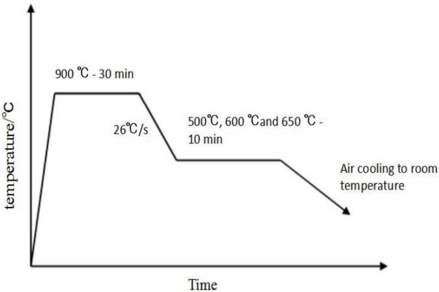
Figure 1. The scheme of heat treatment process of rail samples.
Metals 13 00237 g001
Figure 2. Sampling position and schematic diagram of rolling contact wear sample: (a) sampling position of experimental steel; (b) schematic diagram of rolling contact wear sample.
Metals 13 00237 g002
Figure 3. Weight loss curve of rail sample.
Metals 13 00237 g003
Figure 4. Friction coefficient curves of wheel-rail samples.
Metals 13 00237 g004
Figure 5. SEM pictures of the surface wear pattern of rail samples: (a) large lamellar; (b) medium lamellar; (c) small lamellar.
Metals 13 00237 g005
Figure 6. Rail sample surface plastic deformation layer metallographic photos (h—The depth of plastic deformation layer): (a) large lamellar; (b) medium lamellar; (c) small lamellar.
Metals 13 00237 g006
Figure 7. SEM pictures of fatigue cracks on the surface of rail samples: (a) large lamellar; (b) medium lamellar; (c) small lamellar.
Metals 13 00237 g007
Figure 8. TEM pictures of the plastic deformation layer of the rail sample: (a) large lamellar; (b) medium lamellar; (c) small lamellar.
Metals 13 00237 g008
Table 1. Experimental U75V rail steel and wheel steel composition (wt%).
SteelsCSiMnPSV
U75V rail steel0.760.670.910.0120.0080.06
Wheel steel0.700.360.810.0100.0110.01
measurement uncertainty±0.02±0.02±0.05+0.005+0.005±0.01
Table 2. Pearlite lamellar spacing of U75V rail steel and mechanical properties.
SamplesIsothermal
Temperature/°C
Lamellar
Spacing/nm
Tensile
Strength/MPa
Elongation/%Brinell
Hardness/HB
Large
lamellar
650263107212.6305
Medium lamellar600161121312.1358
Small
lamellar
500104130611.4383
Table 3. Weight loss of rail samples (g).
Samples2 h4 h6 h8 h10 h14 h18 h23 h28 h
Large lamellar0.1180.1870.3230.410.4590.5960.7390.8781.043
Medium lamellar0.0690.1130.1450.1970.2580.3660.4610.5090.551
Small lamellar0.0310.090.1310.1540.1880.1960.2250.2370.254
Table 4. Friction coefficient of wheel-rail samples.
Samples2 h4 h6 h8 h10 h14 h18 h23 h28 h
Large lamellar0.5730.6020.6230.6220.6260.6310.6280.6320.635
Medium lamellar0.5680.6130.6190.6150.6110.6130.610.6020.604
Small lamellar0.5750.6050.5970.6130.6150.590.5920.5870.588
Table 5. U75V rail steels cross-sectional microhardness.
SamplesHardness of Plastic Deformation Layer/HVHardness of Matrix/HVHardening Rate γ/%
Large
lamellar
39231325.24
Medium
lamellar
49637831.22
Small
lamellar
53639635.35
Disclaimer/Publisher’s Note: The statements, opinions and data contained in all publications are solely those of the individual author(s) and contributor(s) and not of MDPI and/or the editor(s). MDPI and/or the editor(s) disclaim responsibility for any injury to people or property resulting from any ideas, methods, instructions or products referred to in the content.