Article

Shear Strength Analysis of Anti-Rust Bolts with a Spiral Oil-Guiding Slot and Oil-Bearing Hole: Simulation and Experiment

School of Aeronautical Engineering, Taizhou University, Taizhou 318000, China
*
Author to whom correspondence should be addressed.
Metals 2023, 13(2), 297; https://doi.org/10.3390/met13020297
Submission received: 11 December 2022 / Revised: 24 January 2023 / Accepted: 30 January 2023 / Published: 1 February 2023
(This article belongs to the Section Metal Failure Analysis)

Abstract

:
This paper studies the shear strength of an anti-rust bolt with a spiral oil-guiding slot and oil-bearing hole by conducting a simulation and experiment. A finite element model with the bolt and the clamp tool is developed for simulating the shearing of the bolt in progressive failure analyses. An indirect method is proposed to generate a spiral entity that can produce excellent spiral elements. A clamp tool is designed for the shear experiment of the bolt. Moreover, a substitute calculation method is presented for the shear strength analysis of the special bolt, and the effect of using the oil-guiding slot on shear strengths is considered by reducing the bolt’s radius. The study results show the following: The results of the simulation are in good agreement with the experimental results. One side of the bolt with the oil-bearing hole is first cut off, and the deviation between the result obtained by using the substitute calculation and the experiment’s result is 7.97%.

1. Introduction

The cabin doors of some equipment’s structures are not often opened or closed, which makes the connecting bolts between them and the structures rust easily. Once the bolts of the cabin door are rusty, maintaining the structures will become difficult; therefore, the rust protection of these bolts must be considered. In order to prevent the bolts from becoming rusty, three methods can mainly be used: The first anti-rust method is to directly paint the covering materials on the surface of the bolts [1], such as the following: painting the lubricating oil, wrapping plastic film, brushing paint, brushing zinc powder, waxing, applying Vaseline, etc. The specific operations of this method are very tedious, and the anti-rust cycle of this anti-rust method is very short; the materials have to be regularly reapplied on the bolts. The second anti-rust method for bolts is to use anti-rust bolt caps [2], and anti-rust oil is stored in the bolt caps so that the anti-rust oil slowly and continuously flows out to cover the surface of the screws for rust protection. The use of bolt anti-rust caps can ensure that the bolts are well lubricated, and this makes maintenance more convenient. There is no need to refuel regularly after a single use of the bolts, reducing the labor intensity of workers. However, there are still some problems with rust protection with respect to bolt anti-rust caps: 1. In the fastening state of the bolts, the oil in the bolt caps often cannot accurately flow to the surface of the bolts that need to be covered. 2. Removing the bolt caps first before installation is necessary, followed by the removal of bolts with anti-rust bolt caps, which renders the bolt removal and installation work more tedious. The third anti-rust method is the design of new anti-rust bolts. The anti-rust function of this bolt is inherent, and its anti-rust design principle is to drill a hole at the screw to store anti-rust oil that will flow from the oil-bearing hole to cover the surface of the screws after the bolts are tightened in order to achieve the anti-rust effect [3]. However, most of these designs do not consider the weakening strength of the bolts or the stress concentration of the bolts after grooving and opening operations.
Research studies on the analysis of the strength of common bolts have been continuous. Cho et al. [4] investigated the bolt-flange fitting and detaching processes by using updated Lagrangian elastoplastic finite element analyses. Liu et al. [5] developed a three-dimensional finite element model to investigate the structural behavior of steel–concrete composite beams with high-strength friction-grip bolted shear connectors. Pilone et al. [6] investigated the failure behavior of connecting bolts used for holding streetlights inside the tunnels of a mountain highway. Du et al. [7] investigated the failure behavior of pultruded fiber-reinforced polymer bolted joints numerically, and proposed a progressive damage analysis material model integrating the nonlinear shear response, Hashin-type failure criteria and strain-based continuous degradation rules. Coelho et al. [8] present a literature review of the state-of-the-art experimental and analytical methodologies adopted in the construction industry for the design of mechanically fastened connections and joints in pultruded fiber-reinforced polymer framed structures. Lee et al. [9] discussed the results of an experimental investigation of the mechanical behavior of single-bolt PFRP connections under tension. Gantes et al. [10] developed a finite element model of simple T-stub steel connections, and the influence of bolt length in the model was investigated. Liu et al. [11] developed an effective finite element model of push-out testing to investigate the ultimate strength and the load-slip characteristics of shear connections using high-strength friction-grip bolt (HSFGB) connectors and geopolymer concrete slabs. Liu et al. [12] conducted tensile experiments with single-lap bolted joints between composite laminate and steel with countersunk fasteners, and developed two three-dimensional explicit finite element models by using Abaqus/Explicit. Ataei and Bradford et al. [13,14,15,16] conducted research on high-strength friction-grip bolted shear connectors. Egan et al. [17] investigated the mechanical behavior of a composite joints incorporating a single countersunk fastener experimentally and numerically. Xin et al. [18] carried out a failure analysis of a single-lap single-bolt composite joint with a countersunk fastener by using a progressive damage model. Turvey et al. [19] determined the stresses on critical planes and around the hole edge in a two-dimensional model of a single-bolt tension joint by using finite element analysis. Atas et al. [20] developed a strength prediction method for bolted joints in CFRP composite laminates using cohesive zone elements. Persson et al. [21] developed a general method for determining stress concentration factors for laminated glass balustrades with two bolts. Juoksukangas et al. [22] developed a testing arrangement to study the effect of different operating and design parameters of a single bolted joint on fretting fatigue life. Lyu et al. [23] investigated the bearing behavior of multi-bolt high-strength steel connections in a single bolt line by the experiment and a numerical analysis. Belardi et al. [24] demonstrated the capabilities of the composite bolted joint element (CBJE) methodology in the framework of a single-lap multi-bolt joints analysis.
However, there is limited research on the shear strength analysis of a bolt with a spiral oil-guiding slot and oil-bearing hole. This paper executes the shear strength analysis of a bolt with a spiral oil-guiding slot and oil-bearing hole by conducting a finite element analysis and experiments. The finite element model with the bolt and the clamp tool is developed for simulating the shearing of a bolt during progressive failure analyses. Throughout the modeling of the process, an indirect method is presented to generate a spiral entity that can obtain excellent elements. The clamp tool is designed for the shear experiment. Moreover, a substitute calculation method is presented for the strength analysis of the special bolt.

2. Finite Element Analysis

2.1. Finite Element Modeling

The bolt with an oil-bearing hole and spiral oil-guiding slot is shown in Figure 1. The length and diameter of the screw are 50 mm and 6 mm, respectively. The width and depth of the spiral oil-guiding slot are 1 mm and 0.5 mm, respectively. The depth and diameter of the oil-bearing hole are 40 mm and 3 mm, respectively. The bolt’s head is 10 mm in length, which is removed in the simplified finite element model. The three-dimensional geometric entity model of the bolt with a spiral oil-guiding slot cannot be directly created in CAE software. As the datum and the leading line can only be selected (the reference cylindrical surface cannot be selected) in the course of the formation of spiral entities, the resulting spiral entity will be separated from the reference cylindrical surface, as shown in Figure 2. Moreover, when the bolt with the spiral oil-guiding slot is created in CAD software, it cannot be meshed by IsoMesh. Therefore, an indirect method is used to create the three-dimensional entity model of the bolt with a spiral oil-guiding slot with the following steps: (1) The leading lines and baselines are established, as shown in Figure 3. (2) Curved surface 1 is formed by inner baselines, inner leading line 1 and inner leading line 2, and curved surface 2 is formed by outer baselines, outer leading line 1 and outer leading line 2 (two leading lines can be selected when a spiral curved surface forms), as shown in Figure 4. (3) The spiral entity is formed by curved surface 1 and curved surface 2. (4) Rotating and translating the spiral entity can obtain the spiral parts of the bolt, and these are named as the outer cylinder of the bolt. The outer cylinder is shown in Figure 5a with a thickness of 0.5 mm, which is the same as the depth of the oil-guiding slot and with a length of 50 mm and diameter of 6 mm. The other part is the inner cylinder of the bolt, as shown in Figure 5b; its diameter is 5 mm, and its length is 50 mm. The diameter of the oil-bearing hole is 3mm in the inner cylinder, and its length is 30 mm, which equals the total length of the hole minus the bolt head’s length. The resulting spiral entity can be meshed by IsoMesh, resulting in excellent spiral elements, as shown in Figure 6. The type of element is an eight-node hexahedron element–, and it possesses a uniform size, with three sizes of 0.4 mm, 0.4 mm and 0.25 mm. When the three sizes of the element change within the range of 0.2–0.6 mm, 0.2–0.6 mm and 0.1–0.5 mm, respectively, the calculation deviation of the model is less than 2%. Therefore, the model exhibits convergence with respect to mesh size. There are two methods for meshing the inner cylinder of the bolt: 1. Spiral meshing—when this method is used, the inner cylinder is connected to the outer cylinder by the merging nodes (multi-nodes sharing the same location are merged into one node). As shown in Figure 7a, the inner cylindrical elements exhibit spiral patterns. 2. The second method is non-spiral meshing. When this method is used, the inner cylinder is connected with the outer cylinder by gluing contact. As shown in Figure 7b, the inner cylindrical element’s edges are parallel to the axis of the bolt.

2.2. Boundary Conditions of the Finite Element Model

The bolt sleeve will have a shear effect on the bolt; therefore, there is a corresponding boundary in the finite element model of the bolt. The boundary conditions of the finite element model of the bolt are as follows: as shown in Figure 8, the bolt passes through the upper and lower parts of the clamp tool and touches them; the upper part of the clamp tool exhibits a length of 25.6 mm, the lower part exhibits a U shape, of which both sides have a length of 12.2 mm; all nodes on both ends of the bolt are connected by RBE2 (Rigid Body Element, Form 2) to the corresponding two nodes (Node 1 and Node 2), constraining the Y-direction displacement of the two nodes; all nodes on the lower surface of the clamp tool are connected to Node 3 by RBE2, constraining all freedoms of Node 3; all nodes on the upper surface of the clamp tool are connected to Node 4 by RBE2, with a 1.5 mm X-direction displacement exerted on Node 4. There is no preload between the bolt and clamp tool, and the stress between them will be generated after loading.

2.3. Progressive Failure Analysis and Material Properties of the Bolt

The bolt is made of steel, its elastic modulus is 206GPa and the Poisson’s ratio is 0.3. The progressive failure analysis is executed in the finite element analysis of the bolt, and the maximum stress criterion is used as the failure criterion. The X-direction tensile strength, Y-direction tensile strength and Z-direction tensile strength are 1078 MPa. The X-direction compression strength, Y-direction compression strength and Z-direction compression strength are 1056 MPa. The X-direction shear strength, Y-direction shear strength and Z-direction shear strength are 441 MPa. The failure index (FI) is the ratio of stress in different directions to the strength of the corresponding direction. When the failure index is less than 1, the material is linearly elastic in the progressive failure analysis. When the failure index is greater than 1, the material’s stiffness begins to decrease, and the reduction coefficient is ri, which is calculated by Formula (1). The elastic modulus of the material after the reduction is equal to the reduction coefficient multiplied by the original elastic modulus. The progressive failure analysis is not executed in the finite element analysis of the clamp tool. The elastic modulus of the clamp tool is 235 GPa, and the Poisson’s ratio is 0.3.
r i = e 1 F I

2.4. Results of the Analysis

The load-displacement curves of the loading node are shown in Figure 9. When the inner cylinder is connected with the outer cylinder by the merging nodes, the maximum load of the bolt is 14,260 N. When the displacement is less than 0.49 mm, the load increases quasi-linearly with the displacement, and then the load increases nonlinearly with the displacement. When the displacement is 0.78 mm, the load reaches the maximum. When the inner cylinder is connected with the outer cylinder by gluing contact, the maximum load of the bolt is 14637N. When the displacement increases from 0 to 0.11 mm, the load has a small fluctuation: it begins to increase and then decreases, and the fluctuation is caused by sliding motions between the outer cylinder and inner cylinder. When the displacement increases from 0.11 mm to 0.49 mm, the load increases quasi-linearly with the displacement, and then the load increases nonlinearly with the displacement. When the displacement is 0.78 mm, the load reaches the maximum. When the load reaches the maximum, the stress distribution of the bolt is shown in Figure 10, and the stress maximum is in the area within a distance of 12.2 mm from both ends (the case for establishing a connection by the merging nodes is consistent with the case for establishing a connection by using gluing contact). The stress distribution of the inner cylinders is shown in Figure 11. When the inner cylinder is connected with the outer cylinder by the merging nodes, the stress of the inner cylinder in the area in the distance of 12.2 mm from the two ends is more concentrated; when the inner cylinder is connected with the outer cylinder by gluing contact, the stress of the inner cylinder is more homogeneous. The difference in the stress distribution of the inner cylinders reflects the difference between the force transfer of two modes of connection: when the merging nodes are used, the force transfer between the nodes is more concentrated; when gluing contact is used, the nodes in the corresponding area are needed for the transferring forces. The bolt is sheared during the progressive failure analysis, as shown in Figure 12; the fracture first occurs at the side with the oil-bearing hole.

3. Shear Experiment of the Bolt

The bolt and clamp tool are shown in Figure 13. The lower part of the clamp tool is used for clamping the bolt, while the upper part of the clamp tool is used for loading the bolt. The left side of the bolt is fixed by the nut, and the right side of the bolt is fixed by the bolt’s head. The load-displacement curves obtained by the experiment are shown in Figure 14. The load increases with the displacement, and when the displacement is 0.808 mm, the load reaches the maximum (13,757 N), and then the load decreases dramatically with the displacement. When the displacement is 0–0.2 mm, the shear stiffness obtained from the experiment is similar to that gained from the simulation. When the displacement is 0.2–0.5 mm, the experimental value is slightly smaller. When the displacement is 0.5–0.63 mm, they become similar again. When the displacement is 0.63–0.78 mm, the experimental value is slightly larger. The destroyed bolt is shown in Figure 15, which is sheared on both sides, and the side with the oil-bearing hole is sheared first.
When the inner cylinder is connected to the outer cylinder by the merging nodes in the progressive failure analysis, the deviation between the maximum load and the experiment result is 3.66%; when the inner cylinder is connected to the outer cylinder by gluing contact in the progressive failure analysis, the deviation between the maximum load and the experimental result is 6.4%. When the method of merging nodes is used as the connection method, the simulated shear stiffness is closer to the experimental value. Evidently, when the inner cylinder is connected to the outer cylinder by the merging nodes in the analysis, the simulation’s results are closer to the experiment’s results.

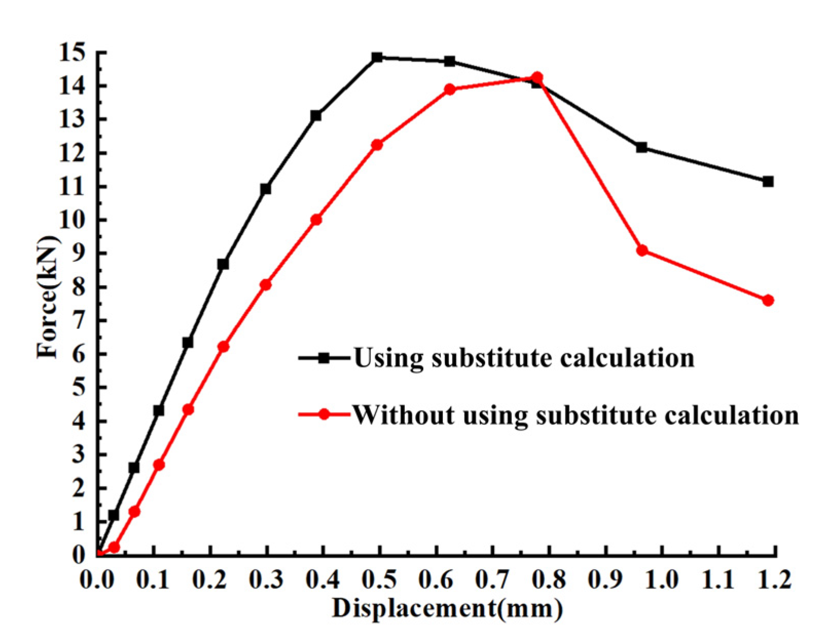
4. Substitute Calculation

Establishing a finite element model of a bolt with a spiral oil-guiding slot is complex. Therefore, a substitute calculation method was introduced to simplify the finite element model. The effect of the oil-guiding slot on the bolt strength is realized by reducing the bolt’s radius, as shown in the Formula (2), in which r is the reduction radius of the bolt, R is the bolt’s radius, W is the width of the oil-guiding slot (1 mm) and H is the depth of the oil-guiding slot (0.5 mm). The reduction radius is 2.946 mm. After the reduction, the finite element model was re-established. The load-displacement curves of the loading node are shown in Figure 16. When the displacement is 0.5 mm, the load reaches the maximum value, 14,853.5 N, which is 7.97% and 4.16% larger than the experiment’s result and the result obtained without using substitute calculations, respectively. Compared with the result obtained without using substitute calculations, when the substitute calculation is used, the load increases quickly before the load reaches the maximum value.
r = π R 2 2 W H π = 2.946

5. Conclusions

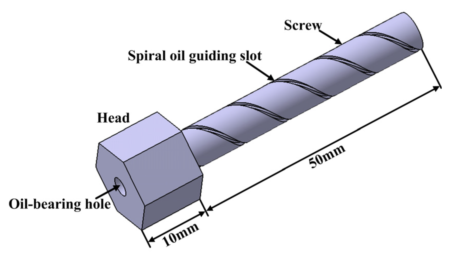
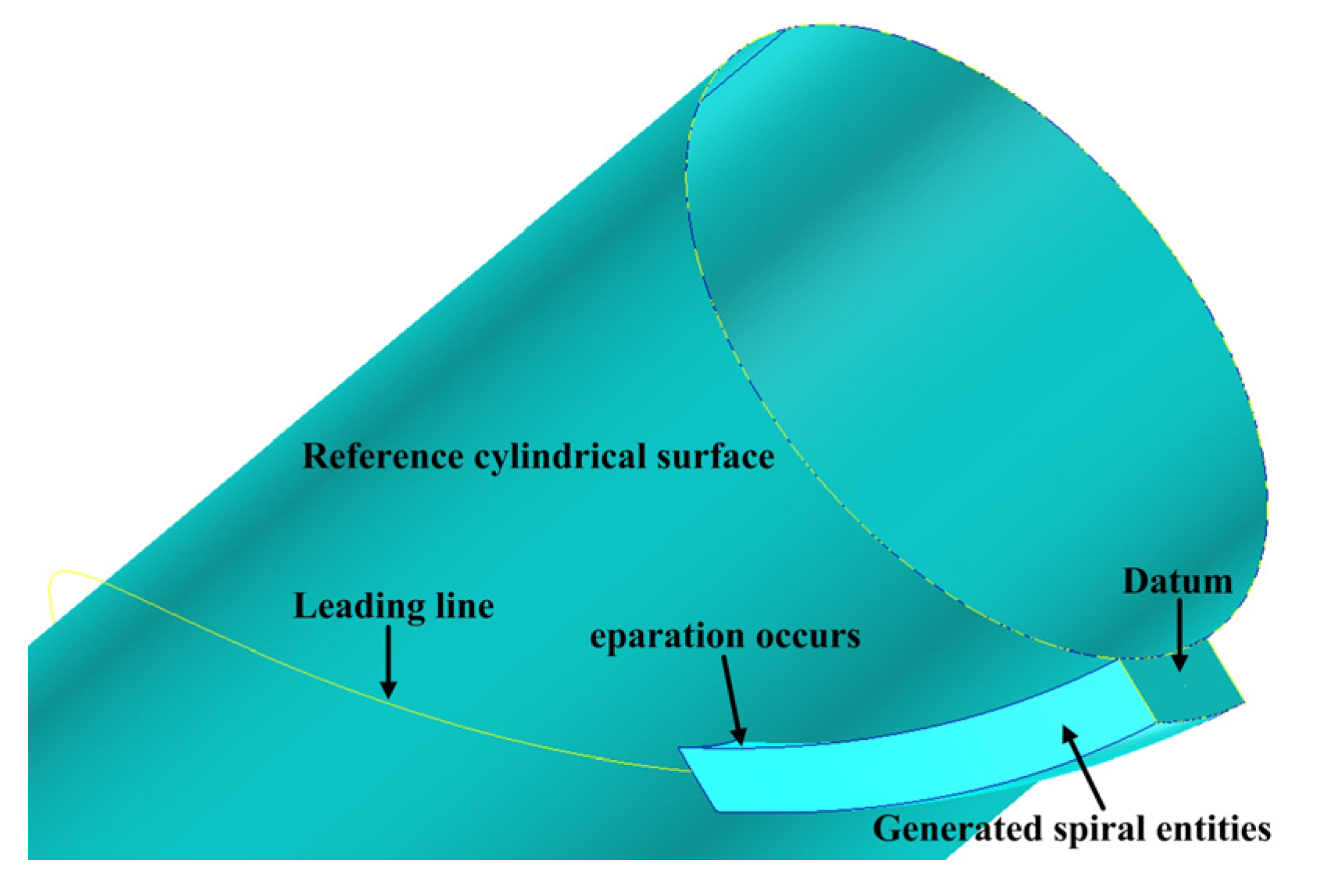
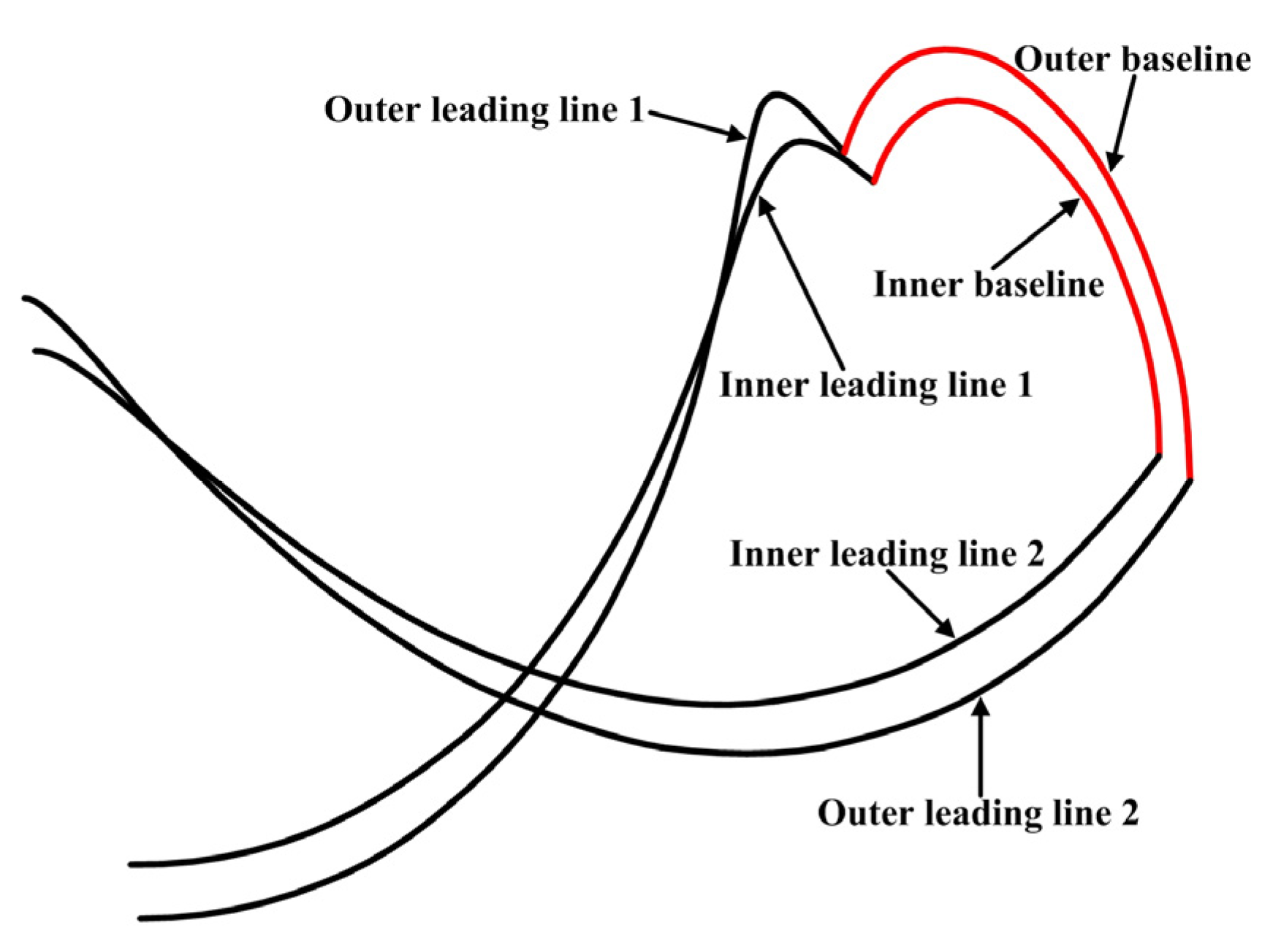
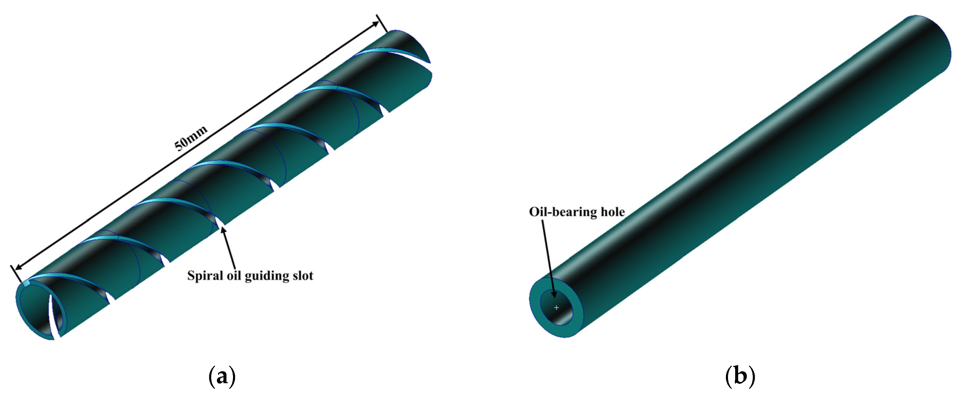
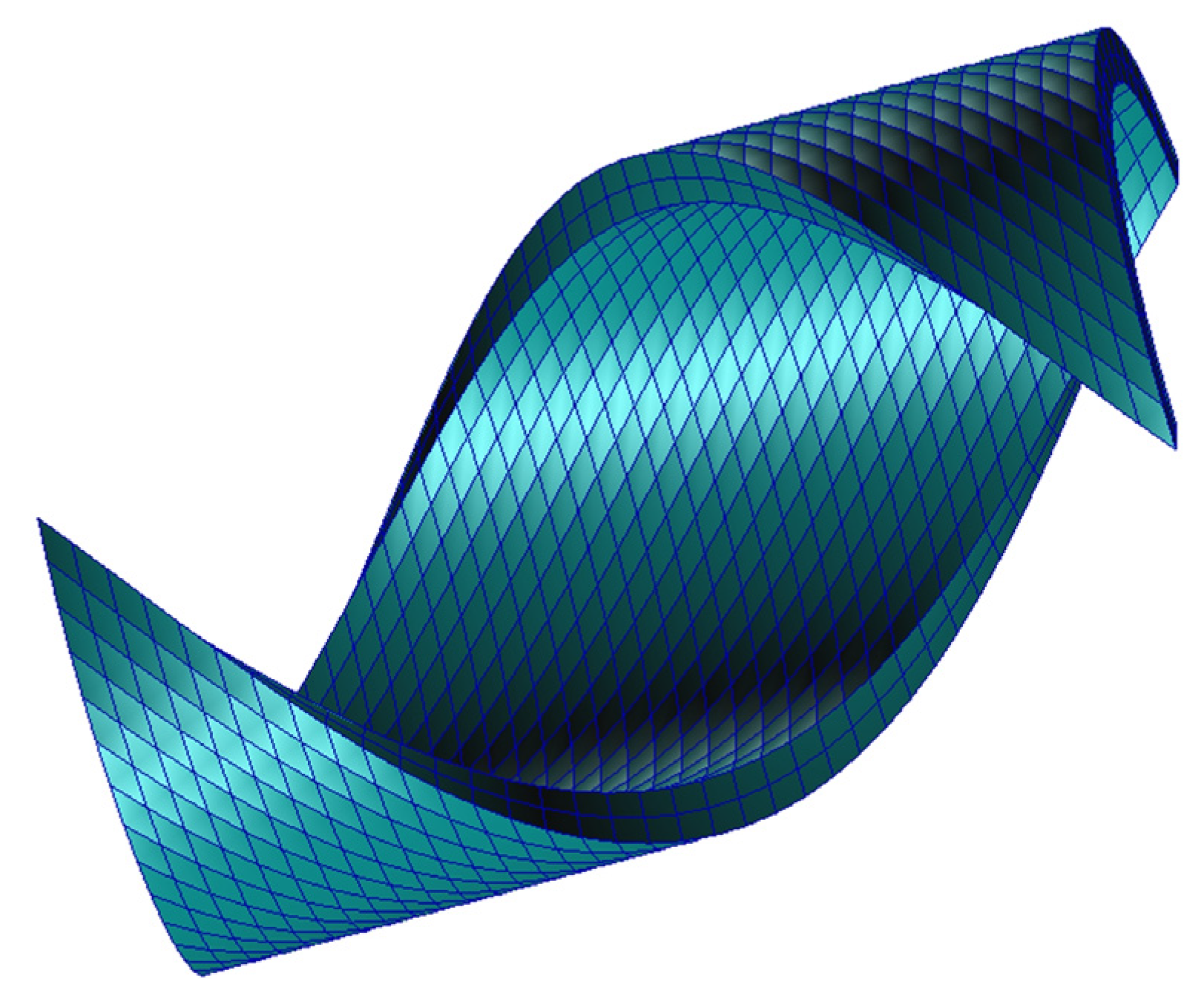
  • The indirect method can be used to obtain spiral entities that can exhibit excellent spiral elements: First, spiral leading lines and baselines are generated; then, spiral surfaces are formed by two spiral leading lines and baselines. Finally, the spiral entity is generated by two corresponding spiral curved surfaces.
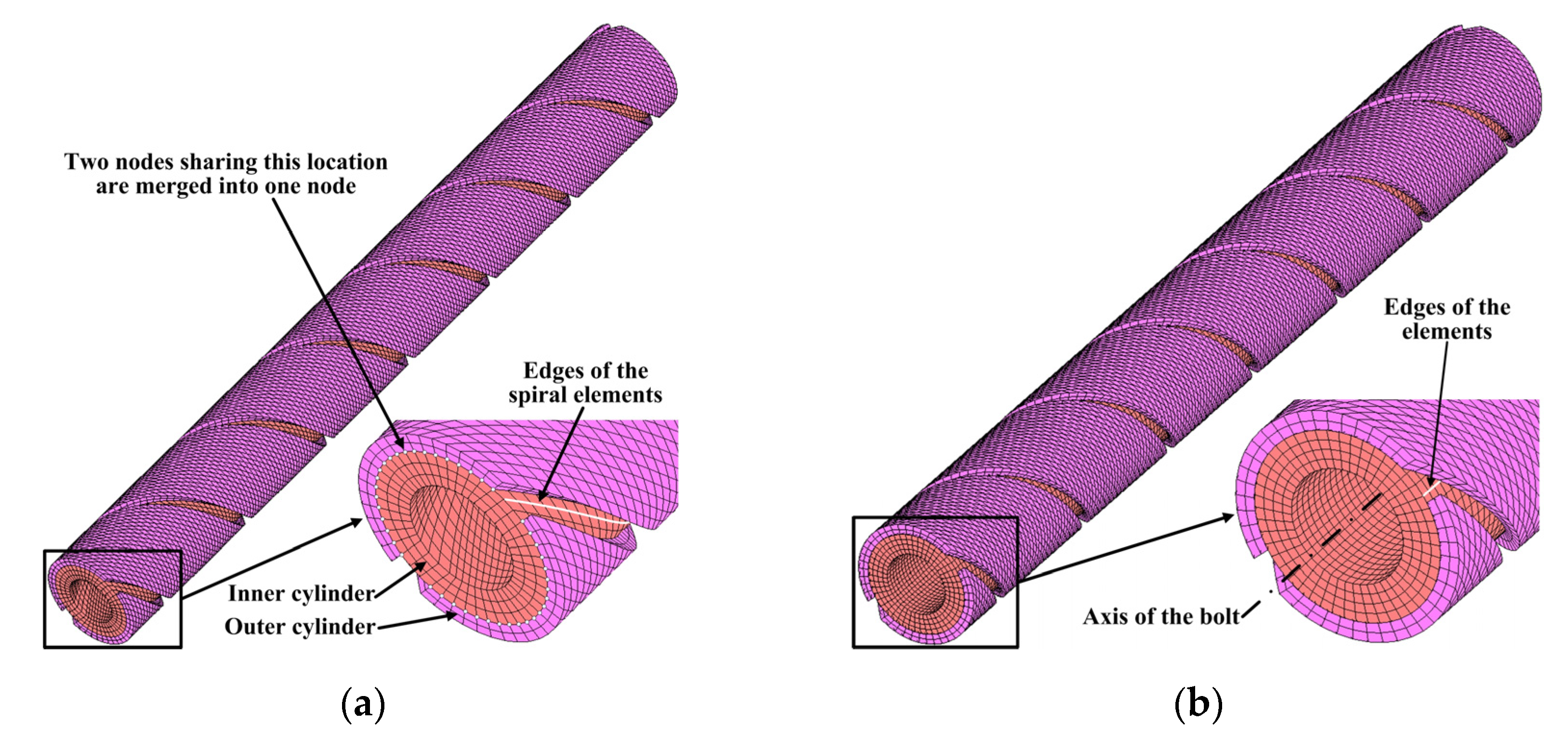
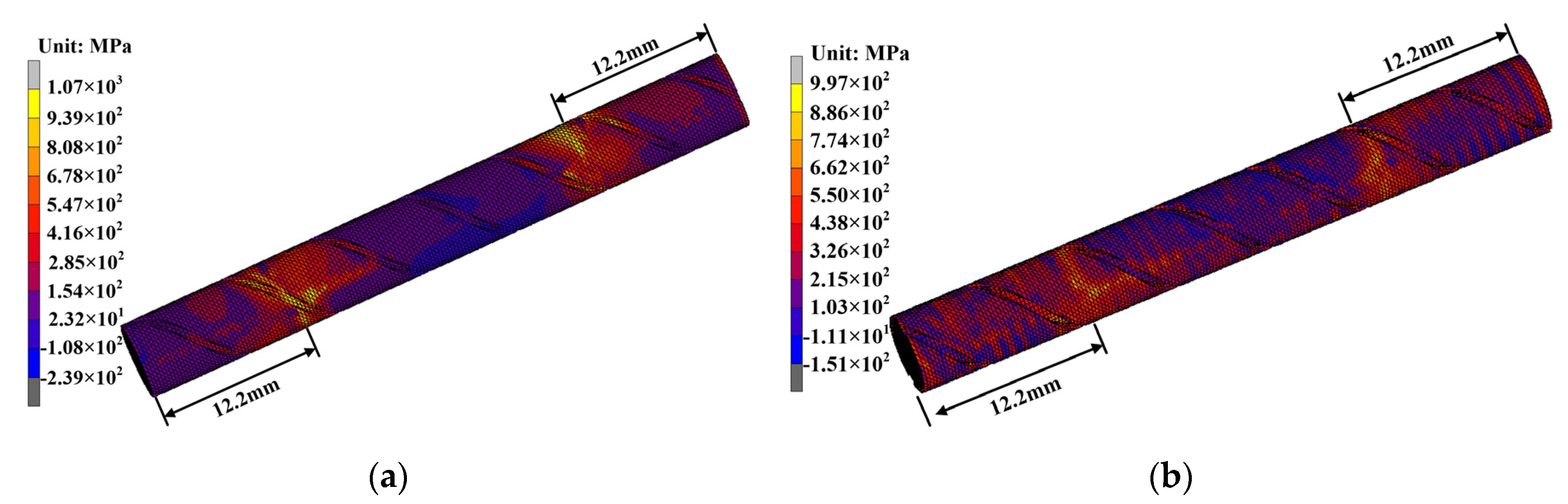
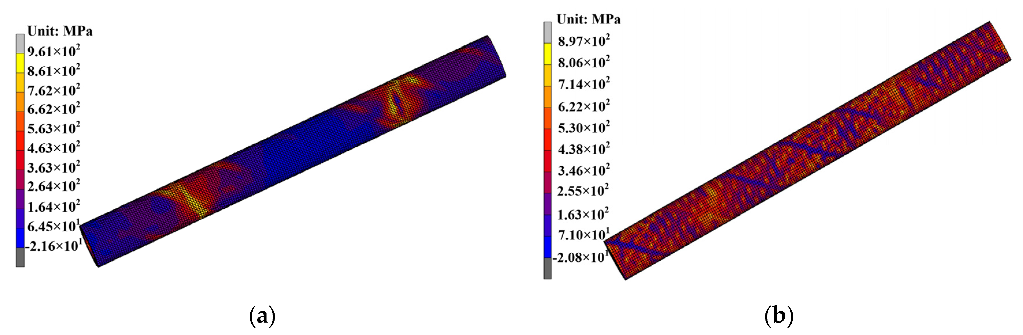
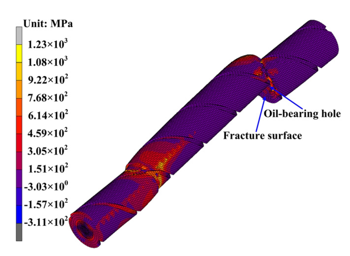
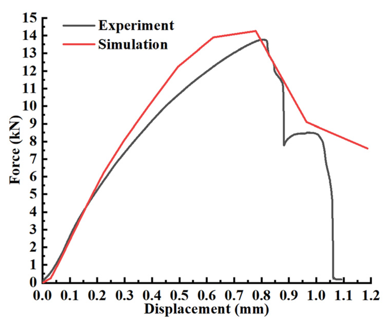
  • When the merging nodes method is used, the force transfer between the nodes is more concentrated; when the gluing contact method is used, the nodes in the corresponding area are needed for transferring forces. The stress exhibited the maximum value in the area within a distance of 12.2 mm from both ends of the bolt. The bolt is sheared on both sides, and the side with the oil-bearing hole is sheared first. The simulation’s results are in good agreement with the experimental results, showing the effectiveness of the bolt’s model in progressive failure analyses.
  • The deviation between the result obtained by using the substitute calculation and the experimental result is small (7.97%).

Author Contributions

Conceptualization, C.L. and H.L.; methodology, C.L.; software, H.L.; validation, C.L. and H.L.; formal analysis, C.L.; investigation, C.L. and H.L.; resources, C.L. and H.L.; data curation, C.L.; writing—original draft preparation, C.L. and H.L.; writing—review and editing, C.L.; visualization, H.L.; supervision, C.L.; project administration, C.L.; funding acquisition, H.L. All authors have read and agreed to the published version of the manuscript.

Funding

This research received no external funding.

Data Availability Statement

The data presented in this study are available on request from the corresponding author.

Conflicts of Interest

The authors declare no conflict of interest.

References

  1. Lev, B.; Bortnik, L. Anti-Rust Coating. WO2002060999A1, 8 August 2002. [Google Scholar]
  2. Wang, J. Antirust Bolt Cover. CN201120434031X, 12 September 2012. [Google Scholar]
  3. Weeder, S.; Vavruch, P. Improving anti-rust property of EP industrial gear oil. Ind. Lubr. Tribol. 2002, 54, 219–224. [Google Scholar] [CrossRef]
  4. Cho, J.R.; Lee, D.Y.; Yoo, W.S.; Lim, O.K. Numerical investigation of bolt fitting and fastening forces by elastoplastic finite element analysis. Int. J. Adv. Manuf. Technol. 2013, 66, 71–81. [Google Scholar] [CrossRef]
  5. Liu, X.; Bradford, M.A.; Chen, Q.J.; Ban, H. Finite element modelling of steel-concrete composite beams with high-strength friction-grip bolt shear connectors. Finite Elem. Anal. Des. 2016, 108, 54–65. [Google Scholar] [CrossRef]
  6. Pilone, D.; Brotzu, A.; Felli, F. Failure analysis of connecting bolts used for anchoring streetlights of a mountain highway. Eng. Fail. Anal. 2015, 48, 137–143. [Google Scholar] [CrossRef]
  7. Du, A.; Liu, Y.; Xin, H.; Zuo, Y. Progressive damage analysis of PFRP double-lap bolted joints using explicit finite element method. Compos. Struct. 2016, 152, 860–869. [Google Scholar] [CrossRef]
  8. Coelho, A.M.G.; Mottram, J.T. A review of the behaviour and analysis of bolted connections and joints in pultruded fibre reinforced polymers. Mater. Des. 2015, 74, 86–107. [Google Scholar] [CrossRef]
  9. Lee, Y.G.; Choi, E.; Yoon, S.J. Effect of geometric parameters on the mechanical behavior of PFRP single bolted connection. Compos. Part B Eng. 2015, 75, 1–10. [Google Scholar] [CrossRef]
  10. Gantes, C.J.; Lemonis, M.E. Influence of equivalent bolt length in finite element modeling of T-stub steel connections. Comput. Struct. 2003, 81, 595–604. [Google Scholar] [CrossRef]
  11. Liu, X.; Bradford, M.A.; Lee, M.S.S. Behavior of High-Strength Friction-Grip Bolted Shear Connectors in Sustainable Composite Beams. J. Struct. Eng. 2015, 141, 04014149. [Google Scholar] [CrossRef]
  12. Liu, P.; Cheng, X.; Wang, S.; Liu, S.; Cheng, Y. Numerical analysis of bearing failure in countersunk composite joints using 3D explicit simulation method. Compos. Struct. 2016, 138, 30–39. [Google Scholar] [CrossRef]
  13. Ataei, A.; Bradford, M.A.; Valipour, H.R.; Liu, X. Experimental study of sustainable high strength steel flush end plate beam-to-column composite joints with deconstructable bolted shear connectors. Eng. Struct. 2016, 123, 124–140. [Google Scholar] [CrossRef]
  14. Ataei, A.; Bradford, M.A.; Valipour, H.R. Experimental study of flush end plate beam-to-CFST column composite joints with deconstructable bolted shear connectors. Eng. Struct. 2015, 99, 616–630. [Google Scholar] [CrossRef]
  15. Ataei, A.; Bradford, M.A.; Liu, X. Experimental Study of Flush End Plate Beam-to-Column Composite Joints with Precast Slabs and Deconstructable Bolted Shear Connectors. Structures 2016, 7, 43–58. [Google Scholar] [CrossRef]
  16. Ataei, A.; Bradford, M.A.; Liu, X. Experimental study of composite beams having a precast geopolymer concrete slab and deconstructable bolted shear connectors. Eng. Struct. 2016, 114, 1–13. [Google Scholar] [CrossRef]
  17. Egan, B.; Mccarthy, C.T.; Mccarthy, M.A.; Gray, P.J.; Frizzell, R.M. Modelling a single-bolt countersunk composite joint using implicit and explicit finite element analysis. Comput. Mater. Sci. 2012, 64, 203–208. [Google Scholar] [CrossRef]
  18. Xin, A.; Zhao, L.B. Failure Analysis of Single-Lap Single-Bolt Composite Joints with Countersunk Fasteners. Appl. Mech. Mater. 2014, 620, 425–428. [Google Scholar] [CrossRef]
  19. Turvey, G.J.; Wang, P. An FE Analysis of the Stresses in Pultruded GRP Single-Bolt Tension Joints and Their Implications for Joint Design. Comput. Struct. 2008, 86, 1014–1021. [Google Scholar] [CrossRef]
  20. Atas, A.; Soutis, C. Strength prediction of bolted joints in CFRP composite laminates using cohesive zone elements. Compos. Part B Eng. 2014, 58, 25–34. [Google Scholar] [CrossRef]
  21. Persson, K.; Froling, M. Designing Bolt-Fixed Laminated Glass with Stress Concentration Factors. Struct. Eng. Int. 2013, 23, 55–60. [Google Scholar]
  22. Juoksukangas, J.; Lehtovaara, A.; Mantyla, A. Experimental and numerical investigation of fretting fatigue behavior in bolted joints. Tribol. Int. 2016, 103, 440–448. [Google Scholar] [CrossRef]
  23. Lyu, Y.F.; Li, G.Q.; Wang, Y.B.; Li, H.; Wang, Y.Z. Bearing behavior of multi-bolt high strength steel connections. Eng. Struct. 2020, 212, 110510. [Google Scholar] [CrossRef]
  24. Belardi, V.G.; Fanelli, P.; Vivio, F. Analysis of multi-bolt composite joints with a user-defined finite element for the evaluation of load distribution and secondary bending. Compos. Part B Eng. 2021, 227, 109378. [Google Scholar] [CrossRef]
Figure 1. The bolt with an oil-bearing hole and spiral oil-guiding slot.
Metals 13 00297 g001
Figure 2. Generated spiral entities.
Metals 13 00297 g002
Figure 3. Leading lines and baselines.
Metals 13 00297 g003
Figure 4. Spirally curved surfaces.
Metals 13 00297 g004
Figure 5. Outer cylinder and inner cylinder of the bolt: (a) outer cylinder of the bolt; (b) inner cylinder of the bolt.
Metals 13 00297 g005
Figure 6. Spiral elements of the spiral entity.
Metals 13 00297 g006
Figure 7. Finite element model of the bolt: (a) the inner cylinder is connected with the outer cylinder by merging nodes; (b) the inner cylinder is connected with the outer cylinder by gluing contact.
Metals 13 00297 g007
Figure 8. Boundary conditions of finite element model of the bolt and clamp tool.
Metals 13 00297 g008
Figure 9. Load-displacement curves.
Metals 13 00297 g009
Figure 10. Von Mises stress distribution of the bolt (when the load reaches the maximum): (a) connected by merging nodes; (b) connected by gluing contact.
Metals 13 00297 g010
Figure 11. Von Mises stress distribution of the inner cylinder of the bolt (when the load reaches the maximum): (a) connected by merging nodes; (b) connected by gluing contact.
Metals 13 00297 g011
Figure 12. Von Mises stress distribution of the fracture bolt.
Metals 13 00297 g012
Figure 13. Bolt and clamp tool.
Metals 13 00297 g013
Figure 14. Load-displacement curves obtained by the experiment and simulation (merging nodes).
Metals 13 00297 g014
Figure 15. Destroyed bolt in the experiment.
Metals 13 00297 g015
Figure 16. Load-displacement curves using substitute calculations.
Metals 13 00297 g016
Disclaimer/Publisher’s Note: The statements, opinions and data contained in all publications are solely those of the individual author(s) and contributor(s) and not of MDPI and/or the editor(s). MDPI and/or the editor(s) disclaim responsibility for any injury to people or property resulting from any ideas, methods, instructions or products referred to in the content.

