Abstract
Brake-wear particle emissions are the result of the components of a friction brake being in tribological contact, and they are classified as non-exhaust emissions. Since most of the emitted particles belong to the size classes of particulate matter (≤10 μm) and differ significantly in terms of their physico-chemical properties from automotive exhaust emissions, this source is of particular relevance to human health and, therefore, the focus of scientific studies. Previous studies have shown that coated brake discs offer significant wear and emission reduction potential. Nevertheless, no studies are available that describe the specific particle formation process, the contact conditions, the structure of the friction layer and the differences compared to conventional grey cast iron discs. The aim of this study is to describe those differences. For this purpose, the tribological behaviour, the structure of the friction layer and the associated particle dynamics within the friction contact between a laser cladding coated disc and a conventional grey cast iron disc are compared. The required investigations are carried out both ex situ (stationary) and in situ (dynamic). Parallel to the tribological investigations, the particle emission behaviour is determined on an inertia dynamometer using a constant volume sampling system (CVS) and equipment for particle number and particle size distribution measurement. The results show that, for two different brake pads, the laser cladding brake disc has lower wear and less particulate emissions than the grey cast iron brake disc. The wear behaviour of the coating varies significantly for the two brake pads. By contrast, the grey cast iron brake disc shows a significantly lower influence.
1. Introduction
The strong limitation of exhaust emissions and the minimisation of this source of particulate matter has put non-exhaust emissions in the focus of research and politics. The friction brake, which is a tribological system involving a brake disc and brake pad, accounts for a large percentage of these emissions [1,2]. In the course of preparing legislation to limit brake particulate matter, some reduction measures are already available for market introduction [3,4]. One way to reduce the fine dust emissions from friction brakes is to use coated brake discs [5,6,7]. They have the additional advantage of increasing the lifetime of the tribological system because of the increased wear resistance. Furthermore, the coating of the brake disc can improve the corrosion resistance of the friction surfaces. In some cases, this brake system also has better brake performance [7].
In the past, many studies have been carried out on the wear and emission behaviour of coated brake discs. The coated brake discs show significant reduction potential compared to grey cast iron friction couples and can make a significant contribution to compliance with future limits concerning brake emissions [5,6]. However, the reduction potential can vary greatly between coating technologies and material variations, as well as between the brake pads that are used [8]. Furthermore, investigations have shown that the coefficient of friction of coated discs decreases under high-friction work [9]. The reduction potential decreased and nanoscale particles are formed [6,8]. A comparison of the emission behaviour of a conventional grey cast iron disc to a coated disc is shown in Figure 1. The study carried out by Gramstat [6] showed a reduction in particulate emissions by a factor of three under Worldwide harmonized Light-Duty vehicles Test Procedure (WLTP) brake conditions [10]. In the tests, the brake emissions were measured for Section 10 (sec10) of the WLTP brake cycle. This section contains the highest relative speeds and highest decelerations of the cycle. For this reason, the emission result is to be regarded as a worst-case scenario.
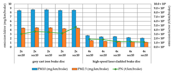
Figure 1.
Comparison of the emission behavior between the number and mass-related emission factors of both friction materials.
For a tribological explanation of the emission reduction potential of coated brake discs, it is necessary to observe the processes that occur in frictional contact more closely. This makes it possible to derive the mechanisms and interactions that influence the wear particle formation process. Considering these facts, it is possible to influence the coating process and the material selection in order to comply with future limits. In addition, it is possible to design the coating as a functional layer in order to comply with the large number of requirements. Furthermore, it must be examined whether existing wear models and processes occurring in frictional contact can be similar to those of coated brake discs.
The current study aims to describe and demonstrate the different tribological behaviour of a coated brake disc compared to a grey cast iron brake disc with different parameters. The investigations are based on the example of one load profile. The bedding process of the friction partners is also observed. The surface quality, the coefficient of friction, the wear, a chemical analysis and the particle size are used as evaluation parameters. For the comparison, two different friction materials are tested, which were developed for the corresponding brake discs. The particulate matter investigations and the classification of the reduction potential of these friction pairings have already been part of earlier investigations [6].
2. Experimental
2.1. Method
To achieve a detailed description of the tribological behaviour of brake friction couples, the procedure shown in Figure 2 is used.
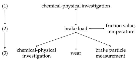
Figure 2.
Scheme of the investigation method.
The friction partners are prepared during and after the manufacturing process for individual requirements. For this purpose, manufacturers use many different methods (disc: grinding, turning, anti-corrosion coatings, etc.; brake pad: grinding, scorching, etc.). The friction partners are examined chemically (energy-dispersive X-ray spectroscopy [EDXS]) and physically (microscope) in the new condition. This has the advantage that any phenomena occurring during the bedding process can be detected. During the bedding process, the typically measured variables on the dynamometer, such as the brake pressures, brake torques and brake temperatures, can also be measured. These measured variables can be used to make a statement about the friction behaviour.
Since the initial condition of the friction partners is measured, a description of the change in the measured variables can be made after the application of the tribological load. With the help of this knowledge, it is possible to understand the wear process and identify modifications in the manufacturing process of the friction partners. By measuring the wear and brake particles, it is possible to confirm the chemical and physical analysis findings. Furthermore, the tribological system can be better characterised. Based on the findings, measures can be identified to improve the wear and emission behaviour.
For the investigation of the tribological behaviour, a conventional grey cast iron friction pairing and a coated friction pairing are examined. In order to describe the wear effects, the friction partners are tested among each other. Figure 3 shows the test combinations of the friction partners.
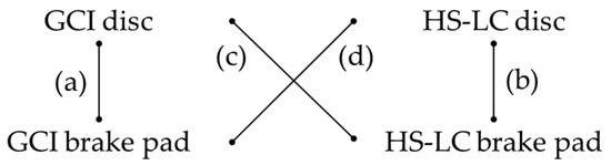
Figure 3.
Comparison of the investigated friction partners.
The comparison of the friction partners with each other offers the possibility of examining the material-specific features among each of them. Furthermore, the advantages and disadvantages of the coated friction pairing compared with the grey cast iron can be determined. The four friction pairings are loaded with a bedding process that is standard in the industry. The result after the load is a quasi-stationary tribological condition, which forms the basis for the comparison.
2.2. Brake System and Friction Materials
With regard to the wear mechanisms of the alternative friction materials, a conventional grey cast iron brake disc (GCI, diameter: 318 mm) is compared with a coated brake disc (HS-LC, diameter: 318 mm). The brake discs are geometrically identical and have radial internal ventilation. The grey cast iron brake disc is a serial product, while the coated disc is a prototype. The coating was applied to the surface using high-speed laser cladding (HS-LC). The coating consists of a stainless steel buffer layer (316L) and a top stainless steel friction layer (316L), with spherical tungsten carbide particles (WSC) serving as a reinforcement phase. The friction surface is a composite material. The WSC particles have an average diameter of 23 µm. The adhesive layer has a thickness of approximately 100 µm and the friction layer of 200 µm. The friction layer is designed in a ratio of 70 vol% 316L to 30 vol% WSC. Metallographic cross-sections of both brake discs can be seen in Figure 4. In both cases, the basic material of the brake discs is made of lamellar grey cast iron.
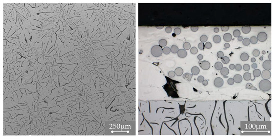
Figure 4.
Microstructures of the metallographic cross-sections of the brake disc (SEM)—(left): GCI; (right): HS-LC.
Low-steel brake pads (often referred to as ECE brake pads) were tested for the comparison of the two brake discs. One of the brake pads was a prototype brake pad specially developed for the coating disc. The surface structures of the two brake pads are shown in Figure 5. The white elongated formations are iron fibres.
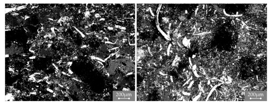
Figure 5.
Comparison of friction materials (SEM)—(left): GCI brake pad; (right): HS-LC brake pad.
The chemical composition of the prototype brake pad is very similar to that of the ECE standard brake pad. Six different locations were analysed for each brake pad. The mean composition is shown in Table 1. The elemental proportions were determined using a EDXS analysis (JEOL GmbH, Freising, Germany; JEOL JSM-6610). In addition, the proportions of Mg, Al, Si, S, Ca, Fe, Zn and Sn can be detected in all the brake pads. What differs is that the friction materials of the laser cladding disc contain Ti and Cr. Moreover, Cu is also detected in the GCI brake pad. It can be assumed that the chemical combinations of the individual brake pads are more different.

Table 1.
Chemical composition of the new brake pads (GCI, HS-LC)—EDXS analysis.
2.3. Brake Dyno and Dilution Tunnel
All the brakes were tested on an inertia dynamometer (Link Engineering Company GmbH, Limburg, Germany; Link 3900 NVH) in a fully air-conditioned test chamber. On the dyno, the engine speed and brake pressure can be dynamically adjusted for the desired test. The dyno has three mechanical inertia masses (47.46 kgm2, 75 kgm2 and 75 kgm2) and an electrical inertia simulation. This means that any vehicle inertia can be simulated. The climatic chamber can be controlled in a temperature range from −20 °C to 50 °C, and the relative humidity in a range from 15% to 85%. The cooling volume flow on the brake can be adjusted synchronously with the test bench speed. The test rig is a multipurpose one, and it can be equipped with extensive emission measurement technology for the classification of brake particulate matter [4]. The test bench thus offers a high degree of flexibility with respect to the research topics to be investigated. A comparable test bench setup can be seen in Figure 6. For the tests, a constant volume sampling (CVS) box with a Dekati ELPI + aerosol analyser (ENVILYSE GmbH, Essen, Germany) was used to investigate the size of the emitted particles. The ELPI uses a unipolar corona charger to prepare the particle charge, although it uses impactors to classify the size of the charged particles. The ELPI has 13 impactor stages and a backup filter stage to span the aerodynamic mobility size range from 6 nm to ~10,000 nm. Calculating the size distribution of the electric mobility using the ELPI requires an assumption regarding the effective particle density, which can generally depend on the particle size and composition of the friction material. For uniform assumptions in this study, the calculation of the size-resolved number concentration is performed with a uniform density of 1 g/cm3 (corresponding to the aerodynamic diameter).
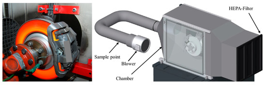
Figure 6.
(Left): example knuckle fixture on the dyno; (right): CVS system for brake particle measurement.
The front axle brake (B-segment vehicle) is investigated under identical test conditions. The brake system tested is a fist-type calliper brake system. The brake was tested on a knuckle fixture on the dyno. The vehicle was simulated on the dynamometer with a moment of inertia of 73.78 kgm2 and a dynamic rolling radius of 335 mm. This corresponds to a vehicle weight with a maximum payload reduced by the driving resistances (13% deduction from the moment of inertia).
2.4. Microscope Technology
Two different types of optical microscopes were used to analyse and describe the tribological changes in the friction couples. The laser scanning microscope (LM) (KEYENCE DEUTSCHLAND GmbH, Neu-Isenburg, Germany; Keyence VK-X100) and the digital microscope (DM) (KEYENCE DEUTSCHLAND GmbH, Neu-Isenburg, Germany; Keyence VHX-7000) are shown in Figure 7. The microscopes have special holders for the brake pads and brake discs, meaning that reproducible movement of the samples on the integrated x-y stage is possible.
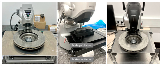
Figure 7.
Keyence microscope technology—(left): laser scanning microscope (LM); (right): digital microscope (DM).
A laser scanning microscope was used for the accurate measurement of surface structure and roughness. It is a non-contact measuring device that works according to the confocal principle. The brake pad was observed under the microscope with a 20× objective and the brake disc with a 50× objective. The choice of magnification was a compromise solution between the level of detail and the maximum area that could be analysed. The images obtained with the laser scanning microscope were taken reproducibly at 15 different locations on the brake pad (3 × inlet, 9 × centre, 3 × outlet) and at 8 different locations on the brake disc (4 × from the inside to the outside and rotated by 180°). The positions of the measuring points on the samples are shown schematically in Figure 8.
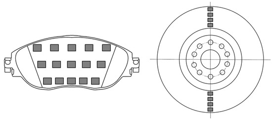
Figure 8.
Scheme for marking the measurement points.
The number of measurement points and the size were selected in such a way that a statistical validation of the respective surface was guaranteed. The size of the brake pad per measurement was 2070 µm × 2760 µm, while for the brake disc it was 820 µm × 1090 µm. The surfaces were additionally blown with compressed air (<1 bar, distance 500 mm) to minimise the influence of loose brake dust. Preliminary tests have shown that blowing the surfaces has a positive influence on the investigation of the actual friction layer. The surface parameters were the mean values of all the measuring points. From the literature, many parameters are relevant for describing a surface in tribological contact. These are divided into the line roughness (DIN EN ISO 4287) and surface roughness (DIN EN ISO 25178-2). The ISO standards describe certain 2D and 3D surface parameters that can be used to classify a surface. For the description of the surface of the brake components, the line roughness is often used [11,12].
The digital microscope was only used for the high-resolution visualisation of the friction surfaces. The magnification was selected individually according to the required level of detail.
2.5. Test Protocol
There are several test protocols for the friction coefficient testing of friction brakes. The SAE J2522 standard describes the friction behaviour of friction couples under a variation of brake pressure, temperature and speed. This standard has become established as the typical friction value measurement, and it is also known as the AK-Master. For this test, it is necessary to have a stable friction coefficient level after the bedding process in order to avoid running-in behaviour during the actual variation of the operating parameters. For this purpose, the standard provides a detailed bedding process, which involves pressure-controlled braking from 80 km/h to 30 km/h at varying brake pressures and an initial braking temperature of 100 °C. The bedding process involves 6 cycles, each of which includes 32 braking operations, i.e., a total of 192 braking operations. Under certain test conditions, a shortening of the bedding process to 2 cycles, i.e., 64 braking operations, is permitted, although it was not considered in this study. The braking pressure varies in the bedding procedure between 15 bar and 51 bar [13].
It is known from the literature that coated brake discs require a longer bedding process to generate a constant friction level [5,6]. Based on this knowledge, a sufficiently long bedding process is necessary for a representative wear condition. For this reason, the complete bedding from the AK-Master was repeated twice. This resulted in a load of 384 braking operations for each friction couple.
3. Results
3.1. Initial Condition of the Components
The surface condition of the green friction partners has a significant influence on the initial friction coefficient and on the bedding process [12,14]. Therefore, a detailed analysis of the green surface is performed using the microscope images and surface parameters [15].
After manufacturing, the cast iron brake disc is finished mechanically to the required surface tolerance. Afterwards, the brake disc gets an anti-corrosion coating. The surface finish is shown in Figure 9. The anti-corrosion coating results in an inhomogeneous surface. The desired coefficient of friction is not achieved until the coating has been removed and the surface has begun to wear.
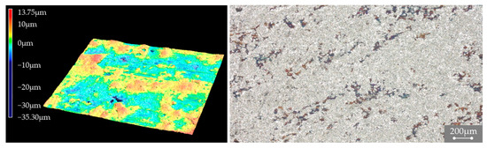
Figure 9.
Surface of the new GCI brake disc—(left): laser scanning microscope; (right): digital microscope.
The surface of the coated brake disc is shown in Figure 10. The surface has a characteristic grinding pattern, which is produced by the final surface finishing after the coating process. The brake discs are mechanically finished to the required tolerance. A closer look at the microscope image using the LM reveals that the spherical tungsten carbide particles that are nearest to the friction surface are removed from the stainless steel matrix by the finishing process. This finishing results in craters or valleys in the friction surface. For this reason, the initial friction surface is primarily made of stainless steel. As a result, the initial wear is increased, and the wear resistance of the brake disc increases continuously due to the exposure of the spherical tungsten carbide particles.
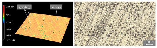
Figure 10.
Surface of the new HS-LC brake disc—(left): laser scanning microscope; (right): digital microscope.
The surface parameters in Table 2 confirm the optically described visual characteristics of the brake disc surface. The surface of the coated brake disc is significantly smoother than that of the grey cast iron brake disc. The disc also has significantly lower peaks and valleys. Despite the craters and valleys, the reduced dale height of the coated brake disc is significantly lower than the irregular surface of the cast iron brake disc.
Table 2.
Surface roughness of the new brake discs.
The brake pad surface is shown as an example in Figure 11. The brake pads have a similar relief surface and are very rough compared to the brake discs. The similarity of the surface could be due to the same manufacturing process (mixing and pressing processes) being used for the brake pads. On initial contact with the brake disc, the raised areas wear first [12]. The large iron fibres shown in Figure 5 are visible in their three-dimensional expression here. The measured data of the surface parameters can be seen in Table 3.
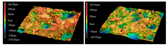
Figure 11.
Surface of the new brake pads (LM)—(left): GCI brake pad; (right): HS-LC brake pad.
Table 3.
Surface roughness of the new brake pads.
3.2. Bedding Process
The bedding process can be described using the friction coefficient curve of the respective friction pairings. From the measured data concerning the brake pressure and brake torque from the dynamometer, an average friction value per braking can be determined. These friction coefficient curves over the AK-Master bedding are shown in Figure 12. The friction value was calculated according to SAE J2522 [13].
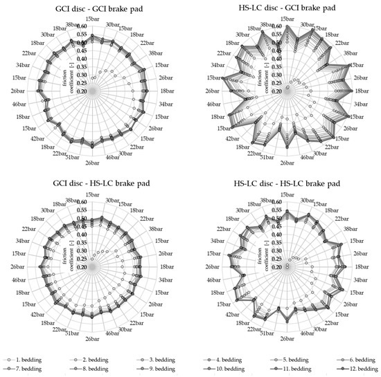
Figure 12.
Mean friction coefficient development over the AK-Master bedding process.
The grey cast iron brake disc with the standard ECE brake pad shows a very strong and continuous increase in the coefficient of friction over the first 13 braking applications. This increase is correlated with the formation of contact areas on the brake pad. During the first 192 brake applications, the coefficient of friction increases successively in small steps. The following brake applications show a stable coefficient of friction, which is between 0.5 and 0.54. At high brake pressures, the friction couple shows a very small but visible brake pressure sensitivity.
The coated brake disc shows completely divergent coefficient of friction behaviour compared with the standard ECE brake pad. Significantly more braking applications are necessary until an acceptable friction coefficient level is reached. After 384 brake applications, the friction coefficient level is not stable. It can be assumed that the friction coefficient would still increase with a further number of braking applications. It can also be seen that the friction coefficient is clearly sensitive to the braking pressure. At high braking pressure, a significant drop in the coefficient of friction can be seen. The coefficient of friction varies in the last AK-Master bedding between 0.44 and 0.61. The coated disc produces higher coefficients of friction compared to the grey cast iron brake disc with the same ECE pad. Furthermore, the friction value is sensitive to the brake pressure.
In the bedding process of the grey cast iron brake disc with the brake pad adapted to the coated brake disc, it becomes clear that more braking applications (approximately 19) are required for an acceptable friction coefficient level. A constant friction coefficient level of between 0.48 and 0.52 is achieved after 256 braking applications. The coefficient of friction is, therefore, somewhat below the standard ECE friction pairing. The brake pressure sensitivity cannot be determined. The differences in the coefficients of friction for the two grey cast iron brake discs show once again that the brake pads differ significantly in terms of their tribological properties, despite the similarities noted at the beginning.
The coated brake disc shows a less fluctuating friction coefficient curve with the adapted brake pad. An acceptable friction coefficient level is reached earlier, and a constant level is reached after around 288 brake applications. The coefficient of friction reaches values between 0.46 and 0.57. The drop in the coefficient of friction at high brake pressures is also measurable, although the fluctuation is significantly lower compared to the standard ECE brake pad. With the adapted brake pad on the coated disc, the friction coefficients are comparable to and, in some places, higher than the grey cast iron disc. Furthermore, the brake pressure sensitivity to the friction value is minimised.
The coated brake disc has a high sensitivity to brake pressure fluctuations for both brake pads. In a direct comparison of the brake pads, the modified brake pad appears to have been adapted precisely to this lower sensitivity. The friction behaviour is confirmed in the wear of the brake components. The mass losses of the friction partners are shown in Table 4. The standard ECE brake pad is significantly more abrasive. As a result, the disc wear is almost double that of the adapted brake pad. The measurement of the coating thickness shows that the coating with the adapted brake pad is 7.5 µm and that with the ECE standard pad is 48.5 µm. It can be assumed that the wear of the coating, with the adapted lining, is predominantly due to the initial wear of the stainless steel. For the series ECE lining and the coated disc, the wear must be viewed critically because the friction layer thickness is subject to heavy wear and the targeted mileages may not be achieved. In the case of brake discs that have run with the adapted brake pad, it can be shown that the wear of the brake pads is significantly greater. Despite the similar chemical composition, two completely different tribological systems can be assumed. The high pad wear with the adapted pad on the coated disc appears to have a positive effect on the coefficient of friction sensitivity.
Table 4.
Wear loss of the brake components.
Basically, the absolute wear shows the enormous advantages of the coated brake disc. Compared to the grey cast iron friction pairing, the wear can be reduced by 74.82% with the ECE brake pad and by 61.21% with the adapted brake pad. In a prior study [6], it was shown that this not only applies to the wear, but also to the particulate emissions of the tested friction partners.
3.3. Surface Roughness
After the bedding process was completed, all the brake components were microscopically imaged again and the surface analysed. For this purpose, all the friction partners were carefully blown with compressed air to remove loose particles. The data concerning the surface characteristics are compared in Table 5. The coated brake disc is still smoother than the grey cast iron disc. However, the surface roughness (Sa), reduced peak height (Spk) and reduced valley height (Svk) of the grey cast iron disc have decreased significantly. The reason for this is the removal of the anti-corrosion coating and the formation of a quasi-stationary state [12].
Table 5.
Surface roughness of the bedded brake discs.
The analysis of the coated discs also shows a reduction in the surface values. However, a completely inverse surface structure forms after the bedding process is completed. The reduced peak height (Spk) and the material volume of the uppermost peaks of the surfaces (Vmp) increase. This change could be associated with the exposure of the tungsten-fused carbide spheres. The raised spheres can be seen in Figure 13. The decrease in the void volume of the valleys of the surface (Vvv) could be predominantly attributed to cracking within the stainless steel matrix. On the one hand, the cracking could be the result of the manufacturing process, while on the other hand, it could be caused by a temperature entry into the disc. The different coefficients of the thermal expansion of the stainless steel, tungsten carbide and grey cast iron are largely responsible for this. The previously known cavities caused by the dissolved spherical tungsten carbide particles can no longer be observed. If a particle is now destroyed, it is filled with wear particles from the pad and disc.
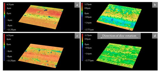
Figure 13.
Comparison of the bedded brake discs (LM)—(a) GCI disc–GCI brake pad; (b) HS-LC disc–GCI brake pad; (c) GCI disc–HS-LC brake pad; and (d) HS-LC disc–HS-LC brake pad.
The surface values of the brake pads are listed in Table 6. Compared to the unbedded state, the brake pads are clearly smoother. Due to the bedding process, the local material peaks have been removed and a uniform, homogeneous pad surface has formed [11]. It is noticeable that the brake pads that have run with the coated brake disc generally have lower surface values and are smoother. This behaviour correlates with the smoother surface of the brake disc. This may indicate lower abrasive wear. In addition, the smoother surfaces can result in larger contact areas. Higher friction values can be measured on the coated disc, although the surface is smoother and, thus, the brake pads hook less easily into the surface. This is an indication of a changed tribological wear mechanism on the coated disc. The surface values of the bedded brake pads are listed in Figure 14.
Table 6.
Surface roughness of the bedded brake pads.
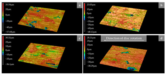
Figure 14.
Comparison of the bedded brake pads (LM)—(a) GCI disc–GCI brake pad; (b) HS-LC disc–GCI brake pad; (c) GCI disc–HS-LC brake pad; and (d) HS-LC disc–HS-LC brake pad.
A comparison of the friction partners shows that the brake disc has no significant influence on the surface parameters of the brake pads. In general, the standard ECE brake pads are rougher on both brake discs and have a larger proportion of peaks and valleys.
3.4. Chemical Composition
After the completion of the bedding process, the brake pad and disc were additionally subjected to a chemical analysis (EDXS) to evaluate the material transfer between the brake pad and disc. The results of the chemical analysis are shown in Figure 15. The chemical analysis of the standard ECE brake pad showed a significant increase in the iron content (Fe). This is the result of a material transfer from the cast iron disc to the brake pad. This material transfer is caused by the embedding of abraded iron particles from the pad and disc into the friction layer [11]. In the case of the coated brake disc, a material transfer from the disc to the brake pad in the form of iron (Fe), chromium (Cr), nickel (Ni) and tungsten (W) can also be measured. The three former originate from the stainless steel matrix (316L), while the tungsten (W) originates from the removed spherical tungsten carbide particles. Based on the disc wear data listed in Table 4, it can be deduced that the material transfer is significantly lower compared to the combination with the cast iron brake disc.
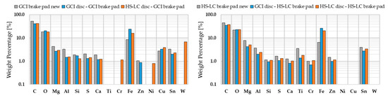
Figure 15.
Chemical composition of the used brake pads—(left): GCI brake pad; (right): HS-LC brake pad.
When using the adapted brake pad and the grey cast iron disc, a strong increase in iron (Fe) could also be detected. In the case of the coated brake disc, there is only a material transfer of iron (Fe). It can be assumed that the measured disc wear also results in particles of tungsten (W), chromium (Cr) and nickel (Ni) on the friction surface. However, these very low concentrations can only be resolved by measurement to a limited extent. This assumption correlates with the low wear of the coated disc for the adapted brake pad.
The surface of the embedded brake pad is shown in Figure 16. In combination with the grey cast iron discs, the iron fibres visible in Figure 5 are no longer recognisable in their original form. Large, raised areas have formed, which are presumably primary patches. Furthermore, many small ferrous components are visible on the brake pad, which could be wear material from the brake disc or from the iron fibres themselves. In general, this observation is most pronounced on the grey cast iron disc with the standard ECE brake pad. The iron fibres in the brake pad that have run on the coated brake disc, on the other hand, predominantly retain their original shape from Figure 5. This indicates that the iron particles do not necessarily act as a primary patch on the brake pad or that they are subject to other wear mechanisms. Furthermore, chromium (Cr), nickel (Ni) and tungsten (W) are present as small wear products on the brake pad, which could be assigned to the disc coating.
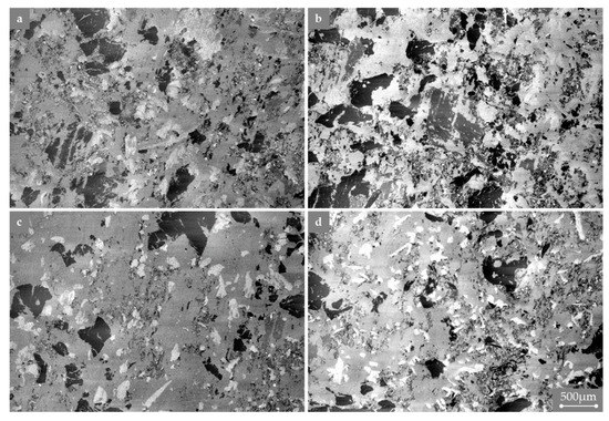
Figure 16.
Comparison of the brake pads (SEM)—(a) GCI disc–GCI brake pad; (b) HS-LC disc–GCI brake pad; (c) GCI disc–HS-LC brake pad; and (d) HS-LC disc–HS-LC brake pad.
Figure 17 shows the surface of the brake discs in the embedded state. Based on the chemical analysis, almost all the components of the brake lining could be detected on the surface. For the coated brake discs, these are mainly wear particles of the destroyed spherical tungsten carbide particles or a tribofilm in the circumferential direction. Furthermore, many small tungsten particles are visible on the brake discs. This confirms the notion that WSC particles are also imprinted in the brake pad surface. However, these are not measurable due to the low wear of the coating. Clear circumferential scoring is visible on the grey cast iron discs. The brake pad components are predominantly visible in the craters of the brake disc.
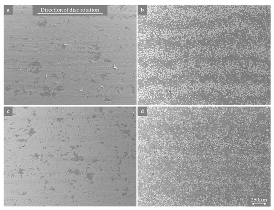
Figure 17.
Comparison of the brake discs (SEM)—(a) GCI disc–GCI brake pad; (b) HS-LC disc–GCI brake pad; (c) GCI disc–HS-LC brake pad; and (d) HS-LC disc–HS-LC brake pad.
On closer inspection of the SEM and DM images (Figure 17 and Figure 18), hardly any shiny stainless steel matrix is visible between the spherical tungsten carbide particles. After exposing the tungsten carbide spheres, a tribofilm was applied to the stainless steel matrix during the bedding process. On the surface of the brake disc, spherical tungsten carbide particles can be seen in the direction of rotation, which act as a hard component and as an obstacle, thereby leading to the formation of the tribofilm. The shape and form of the tribofilm on the brake disc are similar to the formations on the brake pad known from the patch theory. On the surface of the brake disc, the tungsten-fused carbide spheres are very clearly visible when using the ECE standard lining and correspond predominantly in their shape to a sphere. On the surface of the adapted brake pad, the spherical tungsten carbide particles are less visible and often covered with tribofilm or broken and only partly present in their original shape. Furthermore, there is significantly more tribofilm on the disc that has been running with the ECE standard pad. The amount of pad wear listed in Table 4 could be an indication of the clearly pronounced tribofilm formation of the adapted brake pad on the coated disc. This tribofilm can only be observed to a limited extent on the grey cast iron brake disc. Compared to the coated brake disc, it can be easily removed from the surface with compressed air. The surface is additionally characterised by craters and grooves, which is due to the known wear mechanisms [11].
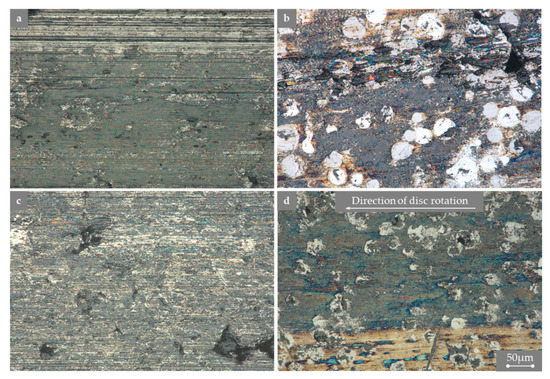
Figure 18.
Comparison of the brake discs (DM)—(a) GCI disc–GCI brake pad; (b) HS-LC disc–GCI brake pad; (c) GCI disc–HS-LC brake pad; and (d) HS-LC disc–HS-LC brake pad.
3.5. Brake Wear Particle
Finally, the emission behaviour of the individual friction partners is analysed. Figure 19 shows the size distribution density for the 15th braking in the corresponding bedding step. Due to the identical load of 30 bar, the individual brake applications can be compared with each other.
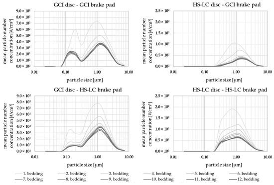
Figure 19.
Comparison of the size distribution of the friction partners for the 30 bar brake application number 15.
As the wear data in Table 4 suggest, the emission behaviour of the grey cast iron friction pair is significantly higher than that of the coated variants. At the last bedding, the particle number concentration varies from 1893 #/cm³ to 130 #/cm³ for the standard ECE pad and from 1565 #/cm³ to 295 #/cm³ for the adapted pad. The advantage in terms of the particle emission behaviour of the coated disc could be confirmed once again. In the course of ongoing bedding, a reduction in the particle emissions can be measured for all the friction pairings. This correlates with the increasing contact ratio of the friction partners. In the case of the coating, the reduction correlates additionally with the exposure of the reinforcement phase. It is noticeable that the coated disc with the adapted pad requires the highest number of bedding cycles until an approximately constant emission level is achieved. Furthermore, at the beginning of the bedding process, all the friction pairings have a change in the size distribution density in the direction of the smaller particles. With the increase in the contact area, the particle size increases continuously up to quasi-stationary emission behaviour. The coated discs emit at a comparable peak between 0.85 µm and 1 µm at the beginning. This could be due to the initial wear of the stainless steel coating. As the bedding steps progress, a wide mode with a count median diameter (CMD) of 0.97 µm is formed for the adapted pad on the coated disc. In comparison, the CMD on the other coated brake disc with the standard ECE brake pad is 1.43 µm. Thus, the size of the wear products for different brake pads varies greatly. The wear mechanisms, such as the shattering of the spherical tungsten carbide particles, seem to be a major reason for this. Figure 20 shows metallographic sections of the two coated discs in the direction of friction.
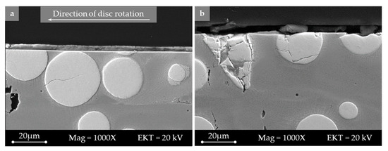
Figure 20.
Comparison of the microstructures of the metallographic cross-section of the brake disc (SEM)—(a) HS-LC disc–GCI brake pad; and (b) HS-LC disc–HS-LC brake pad.
In the case of the ECE series pad, the images of the metallographic cross-section show a very high level of wear on the part of the spherical tungsten carbide particles. The adapted brake pad causes the spherical tungsten carbide particles to crack. This results in a very fissured surface. This finding correlates with the wear pattern in Figure 17 and Figure 18, and it also confirms the assumption that the spherical tungsten carbide particles are subject to highly abrasive wear in the case of the ECE standard pad and surface fracturing in the case of the adapted brake pad. In the case of the adapted brake pad, brake dust collects in the craters of the spherical tungsten carbide particles. The size distribution densities of the grey cast iron friction pairings are comparable to each other. The CMD of the grey cast iron friction pairing is smaller compared to the coating.
4. Discussion
The cross-comparison between the brake discs and the brake pads has shown that the friction values vary significantly between each other. The surface investigations of the friction partners showed that the coated brake disc is significantly smoother than the cast iron disc. The same could be measured for the surfaces of the corresponding brake pads. It can, therefore, be assumed that the wear mechanisms on the coated brake disc are different from those on the grey cast iron brake disc. In a direct comparison of the brake discs, a significant brake pressure sensitivity to the friction value for the coating was demonstrated. The adapted brake pad minimises this sensitivity, although it still occurs. Furthermore, a clear tribofilm on the disc surface was generally detected in the coated brake discs. Other studies [16,17] have also observed that a tribofilm forms on coated brake discs. The tribofilm is more noticeable on the adapted brake pad. This could be a reason for the low brake pressure sensitivity to the friction coefficient. Compared to other studies [18] where significant wear marks formed in the circumferential direction on the spherical tungsten carbide particles, which varied in size, the same could not be observed on the tested components. The spherical tungsten carbide particles are subject to continuous wear in the case of the abrasive series ECE brake pad, while they break apart or disintegrate in the case of the adapted brake pad. The brake pads investigated show different wear mechanisms on the coated brake disc.
The bedding process for the coated brake discs required significantly more brake applications and was not yet completed after 384 brake applications. The main reason for this is the complete exposure of the tungsten carbide reinforcement phase and the resulting development of the tribofilm. This is particularly critical for use in battery electric vehicles. Due to the reduced and less intensive use of the friction brake in regenerative braking systems, an even longer running-in process is expected [19]. For the investigated coating concept, it would be purposeful if, after the coating process, the reinforcing phase is located at the top of the surface and involved in the initial frictional contact. This could accelerate the development of the coefficient of friction.
The patch theory assumes hard components in the brake pad that are significantly involved in the friction force transmitting processes [12,20]. In the case of a coated brake disc, this theory cannot be transferred without further effort. The tungsten carbide reinforcement phase hinders the patch formation on the brake pad. Since the friction coefficients are at least as high as those of the grey cast iron brake disc, the reinforcement phase on the disc and the tribofilm that forms around it seem to have a similar effect as the primary and secondary patches. The tribological wear processes are predominantly dependent on the coating and the brake pad. This shows that existing wear models for grey cast iron friction pairs cannot be transferred to coated brake discs without further effort. Thus, it is necessary to adapt the friction models. With the help of metallographic sections, it was possible to better describe the wear of the coating. This investigative method should be focussed more intensively in the future.
The chemical investigations depicted in Figure 15 have shown that the coating can be found as wear products in the brake lining. From the wear data in Table 4 and the size distribution density in Figure 19, it can be shown that these wear products are released into the environment. However, it has been observed in many studies that nickel and wolfram and their compounds pose a number of hazards to human health [21,22, 23]. Therefore, it is necessary to continue research into alternative coating processes and material combinations.
The wear and particle emission measurements have once again shown the great advantages of the coated brake disc compared to the grey cast iron brake disc. The wear could be reduced by a factor of four. In the case of particle emissions, a reduction of 90% could be achieved under the AKM bedding load. However, the wear and emission behaviour of the tested brake pads varied significantly. In order to achieve lower emission levels in the future, the brake pads must be further optimised and adapted to the respective coatings.
5. Conclusions
A dynamometer study was conducted to compare a conventional grey cast iron brake disc with a laser cladded disc. The two discs were each tested with a standard ECE pad for the cast iron disc and a matched pad for the coated disc. The friction materials were observed in situ (friction coefficient) and ex situ (chemical and physical). The wear products were analysed in terms of the particle number, size distribution density and wear.
The two brake pads generated higher coefficients of friction on the laser-coated disc than the grey cast iron brake disc. The coefficient of friction on the coating reacted sensitivity to high brake pressures.
The particle number concentration was significantly lower compared to the grey cast iron brake disc. The ECE pad emitted a factor of 15 less on the coated disc and the adapted lining a factor of 5 less. The adapted brake pad emitted the particles over a very wide mode and, thus, emitted a larger proportion of fine particles than the standard ECE brake pad on the coated disc. The finest particles were detected on the grey cast iron brake disc. The wear was significantly reduced with the help of the coating.
The analysis of the stressed surface of the friction partners showed that the coated disc had different wear mechanisms than the grey cast iron brake disc.
Author Contributions
Conceptualisation, C.H., K.A., D.S., S.G., A.S., F.G. and D.H.; methodology, C.H., K.A., S.G. and F.G.; validation, C.H. and D.S.; investigation, C.H. and D.S.; resources, S.G., A.S. and F.G.; data curation, C.H. and D.S.; writing—original draft preparation, C.H.; writing—review and editing, C.H., F.G. and D.H; supervision, K.A. and A.S. All authors have read and agreed to the published version of the manuscript.
Funding
This research received no external funding.
Data Availability Statement
Data sharing not applicable.
Acknowledgments
We acknowledge the support for the publication costs provided by the Open Access Publication Fund of the Technical University Ilmenau. The authors would like to thank Henry Romanus from TU Ilmenau, Center of Micro- and Nanotechnologies (ZMN) (DFG RIsources reference: RI_00009), a DFG-funded corefacility (Grant No. MU 3171/2-1 + 6-1, SCHA 632/19-1 + 27-1, HO 2284/4-1 + 12-1) and the BMBF-funded project (project number 16ES0939) for their assistance and support with the SEM/EDX measurements of the brake discs.
Conflicts of Interest
The authors declare no conflict of interest.
Abbreviations
| CMD | Count median diameter |
| CVS | Constant volume sampler |
| DM | Digital microscope |
| ECE | Low-steel brake pad |
| EDXS | Energy-dispersive X-ray spectroscopy |
| ELPI | Electrical low pressure impactor |
| GCI | Grey cast iron |
| HS-LC | High-speed laser cladding |
| LM | Laser scanning microscope |
| Sa | Arithmetical mean height |
| SEM | Scanning electron microscope |
| Spk | Reduced peak height |
| Svk | Reduced dale height |
| Vvv | Dale void volume |
| Vmp | Peak material volume |
| WLTP | Worldwide harmonized Light-Duty vehicles Test Procedure |
| WSC | Spherical tungsten carbide particles |
References
- Pant, P.; Harrison, R.M. Estimation of the contribution of road traffic emissions to particulate matter concentrations from fieldmeasurements: A review. Atmos. Environ. 2013, 77, 78–97. [Google Scholar] [CrossRef]
- Thorpe, A.; Harrison, R.M. Sources and properties of non-exhaust particulate matter from road traffic: A review. Sci. Total Environ. 2008, 400, 270–282. [Google Scholar] [CrossRef] [PubMed]
- Hascoet, M.; Adamczak, L. At source brake dust collection system. Results Eng. 2020, 5, 100083. [Google Scholar] [CrossRef]
- Hesse, D. Beitrag Zur Experimentellen und Analytischen Beschreibung Partikelförmiger Bremsenemissionen. Ph.D. Thesis, Technische Universität Ilmenau, Ilmenau, Germany, 2020. [Google Scholar]
- Hesse, D.; Hamatschek, C.; Augsburg, K.; Weigelt, T.; Prahst, A.; Gramstat, S. Testing of Alternative Disc Brakes and Friction Materials Regarding Brake Wear Particle Emissions and Temperature Behavior. Atmosphere 2021, 12, 436. [Google Scholar] [CrossRef]
- Gramstat, S.; Mertens, T.; Waninger, R.; Augsburg, K.; Hamatschek, C.; Hesse, D. Functional Coatings of Gray-Cast Iron Brake Discs—Impact on the Tribology. In Berichte aus dem μ-Club 2020, Proceedings, S; Springer: Berlin/Heidelberg, Germany, 2021; pp. 162–170. [Google Scholar]
- Hart Wie Diamant Rostet Nicht und Produziert Kaum BREMSSTAUB. Im Neuen Cayenne Turbo ist Die Porsche Surface Coated Brake (PSCB) Erstmals Serienmäßig Im Einsatz. Available online: https://christophorus.porsche.com/de/2017/384/porsche-surface-coated-brake-cayenne-turbo-development-center-weissach-diamond-14479.html (accessed on 4 August 2022).
- Wirth, M. Hard-Metal-Coated brake discs—Impact of chemical and physical characteristics on fine dust emission behavior. In Proceedings of the Eurobrake 2022 Conference, Online, 17–19 May 2022. [Google Scholar]
- Utsch, P. Application development and industrialization of laser based hard coated brake discs. In Proceedings of the Eurobrake 2022 Conference, Online, 17–19 May 2022. [Google Scholar]
- Mathissen, M.; Grochowicz, J.; Schmidt, C.; Vogt, R.; Hagen, F.H.F.Z.; Grabiec, T.; Steven, H.; Grigoratos, T. A novel real-world braking cycle for studying brake wear particle emissions. Wear 2018, 414–415, 219–226. [Google Scholar] [CrossRef]
- Poeste, T. Untersuchungen zu reibungsinduzierten Veränderungen der Mikrostruktur und Eigenspannungen im System Bremse. Ph.D. Thesis, Technische Universität Darmstadt, Darmstadt, Germany, 2005. [Google Scholar]
- Eriksson, M. Friction and Contact Phenomena of Disc Brakes Related to Squeal. Ph.D. Thesis, Uppsala University, Uppsala, Sweden, 2000. [Google Scholar]
- J2522 SEP2014; Dynamometer Global Brake Effectiveness Stabilized J2522 SEP2014. SAE International: Warrendale, PA, USA, 2014.
- Kolbeck, K.; Bernhard, M.; Schröder, T.; Hesse, D.; Augsburg, K. Influence of the Run-in Methodology on the Particle Number Emission of Brakes. In Proceedings of the Eurobrake 2021 Conference, Online, 17–21 May 2021. [Google Scholar]
- Limmer, F.; Paulus, A.; Barton, D.; Brooks, P.; Neville, A.; Kosarieh, S. A comparison of methods for characterizing brake pad surfaces. In Proceedings of the Eurobrake 2020 Conference, Barcelona, Spain, 2–4 June 2020. [Google Scholar]
- Wahlström, J.; Lyua, Y.; Matjeka, V.; Söderberg, A. A pin-on-disc tribometer study of disc brake contact pairs with respect to wear and airborne particle emissions. Wear 2017, 384–385, 124–130. [Google Scholar] [CrossRef]
- Lyu, Y.; Leonardi, M.; Mancini, A.; Wahlström, J.; Olofsson, U. Tribology and Airborne Particle Emission of Laser-Cladded Fe-Based Coatings versus Non-Asbestos Organic and Low-Metallic Brake Materials. Metals 2021, 11, 1703. [Google Scholar] [CrossRef]
- Dizdar, S.; Lyu, Y.; Lampa, C.; Olofsson, U. Grey, Cast Iron Brake Discs Laser Cladded with Nickel-Tungsten Carbide—Friction, Wear and Airborne Wear Particle Emission. Atmosphere 2020, 11, 621. [Google Scholar] [CrossRef]
- Bildstein, M.; Mann, K.; Richter, B. Regenerative braking system. In Fundamentals of Automotive and Engine Technology; Reif, K., Ed.; Springer Fachmedien: Wiesbaden, Germany, 2014; pp. 240–243. ISBN 978-3-658-03971-4. [Google Scholar]
- Leyssens, L.; Vinck, B.; Van Der Straeten, C.; Wuyts, F.; Maes, L. Cobalt toxicity in humans—A review of the potential sources and systemic health effects. Toxicology 2017, 387, 43–56. [Google Scholar] [CrossRef] [PubMed]
- Ostermeyer, G.; Müller, M. New insights into the tribology of brake systems. Proc. Inst. Mech. Eng. Part D J. Automob. Eng. 2008, 222, 1167–1200. [Google Scholar] [CrossRef]
- Denkhaus, E.; Salnikow, K. Nickel essentiality, toxicity, and carcinogenicity. Crit. Rev. Oncol. Hematol. 2002, 42, 35–56. [Google Scholar] [CrossRef] [PubMed]
- Bastian, S.; Busch, W.; Kühnel, D.; Springer, A.; Meißner, T.; Holke, R.; Scholz, S.; Iwe, M.; Pompe, W.; Gelinsky, M.; et al. Toxicity of Tungsten Carbide and Cobalt-Doped Tungsten Carbide Nanoparticles in Mammalian Cells In Vitro. Environ. Health Perspect. 2009, 117, 530–536. [Google Scholar] [CrossRef] [PubMed]


Disclaimer/Publisher’s Note: The statements, opinions and data contained in all publications are solely those of the individual author(s) and contributor(s) and not of MDPI and/or the editor(s). MDPI and/or the editor(s) disclaim responsibility for any injury to people or property resulting from any ideas, methods, instructions or products referred to in the content. |
© 2023 by the authors. Licensee MDPI, Basel, Switzerland. This article is an open access article distributed under the terms and conditions of the Creative Commons Attribution (CC BY) license (https://creativecommons.org/licenses/by/4.0/).