Article

Web Bend-Buckling of Steel Plate Girders Reinforced by Two Longitudinal Stiffeners with Various Cross-Section Shapes

1
Department of Civil Engineering, Ma’anshan University, Ma’anshan 243100, China
2
Department of Civil Engineering, Anhui University of Technology, Ma’anshan 243032, China
3
Department of Civil Engineering, Chonnam National University, Yongbong-ro 77, Buk-gu, Gwangju 61186, Korea
4
Faculty of Civil Engineering, Thuyloi University, 175 Tay Son, Dong Da, Hanoi 100000, Vietnam
5
Department of Structural Engineering, National Technical University of Athens, Zografou, 15780 Athens, Greece
6
Faculty of Civil Engineering, Vietnam Maritime University, 484 Lach Tray Street, Le Chan District, Hai Phong 180000, Vietnam
*
Authors to whom correspondence should be addressed.
Metals 2023, 13(2), 323; https://doi.org/10.3390/met13020323
Submission received: 11 January 2023 / Revised: 31 January 2023 / Accepted: 2 February 2023 / Published: 5 February 2023
(This article belongs to the Topic Numerical Modeling on Metallic Materials)

Abstract

:
This work performs an investigation into the optimal position of two longitudinal stiffeners with different cross-section shapes such as open section (L-shaped and T-shaped) and closed section (rectangular and triangular shapes) shapes of stiffened plate girders under bending loading through an optimization procedure using a gradient-based interior point (IP) optimization algorithm. The stiffener optimum locations are found by maximizing the bend-buckling coefficient, kb, generated from eigenvalue buckling analyses in Abaqus. The optimization procedure efficiently combines the finite element method and the IP optimization algorithm and is implemented using the Abaqus2Matlab toolbox which allows for the transfer of data between Matlab and Abaqus and vice versa. It is found that the proposed methodology can lead to the optimum design of the steel plate girder for all stiffener cross-section types with an acceptable accuracy and a reduced computational effort. Based on the optimization results, the optimum positions of two longitudinal stiffeners with various cross-section shapes are presented for the first time. It is reported that the optimum locations of two longitudinal stiffeners with open cross-section shapes (T- and L-shaped) are similar to that of flat cross-section, while the optimum positions of two longitudinal stiffeners with closed cross-section types (rectangular and triangular sections) are slightly different. One of the main findings of this study is that the bend-buckling coefficient of the stiffened girder having stiffeners with triangular cross-section shape is highest while that with flat cross-section shape is lowest among all considered stiffener types and this latter case has minimum requirement regarding the web thickness.

1. Introduction

Longitudinal stiffeners have been extensively used to improve the buckling strength of steel plates or steel plate girders subject to different loading conditions such as compression, patch loading, combined bending and shear, pure bending, etc. As a result of the significant increase in strength that stiffeners offer when placed at steel plates or steel plate girders, research related to members of this type has been widely conducted. Regarding steel plates reinforced by one or more longitudinal stiffeners under compression, Haffar et al. [1] proposed two new mathematical models for buckling resistance prediction of a steel plate with a closed longitudinal stiffener. Both proposed methods gave similar results, leading to load resistance values of satisfactory precision. Kovesdi et al. [2] investigated the buckling resistance of longitudinally stiffened plates subjected to compression using the shell finite element (FE) method. The author suggested an alternative design procedure to improve the economy of the practical design. Regarding plate girders under patch loading, Loaiza et al. [3] investigated buckling and post buckling behavior of longitudinally stiffened I-girders using an FE simulation. Various hypotheses regarding the effect of vertical and out-of-plane displacements of the web panel on the determination of the critical buckling load of the stiffened plate girder were taken into consideration. The analysis results showed that a full restriction of the vertical and out-of-plane displacements at the stiffener location led to improved patch load resistance at the ultimate load level. Demari et al. [4] performed a numerical study of slender I-girders strengthened with one longitudinal stiffener under patch loading. They reported that the optimum stiffener location for patch loading resistance is closer to the loaded flange when compared to girders under pure bending. Recently, based on an experimental database, Truong et al. [5] proposed an efficient machine learning method, namely the XGBoost algorithm, for predicting the patch load resistance of longitudinally stiffened plate girders. The efficiency and accuracy of the proposed method were demonstrated by comparing its performance with other machine learning methods as well as design equations from the existing standards. Regarding stiffened girders under combined bending and shear, by analyzing various FE models, Truong et al. [6] investigated the influence of multiple longitudinal stiffeners on the ultimate strength of plate girders. It was reported in this research that the variation in the ultimate strength of the girder was almost constant against the various dimensionless geometric parameters. Chen and Yuan [7] conducted a comprehensive experimental and numerical investigation into the local buckling behavior of longitudinally stiffened stainless steel plate girders subjected to combined bending and shear loading. It was observed that the existing M–V interaction curves recommended in EN 1993-1-4 for determining the bending and shear endpoints provide safe-sided estimations with a good level of consistency and accuracy for such structures.
Regarding the case of stiffened girders subjected to pure bending loads, in recent decades, longitudinal stiffeners have been widely utilized in girder webs to enhance the bending strength of the stiffened girder with slender sections. It has been reported that longitudinal stiffeners with various cross-section types, consisting of open cross-sections (flat, T, and L sections) and closed sections (rectangular, triangular, and trapezoidal sections) have been used for this purpose. Research related to the bending response of plate girders strengthened by longitudinal stiffeners has been extensively conducted all over the world, especially for flat stiffeners. Regarding the optimization problem of a single longitudinal stiffener with a flat cross-section, many researchers have proposed that the optimum position of a single longitudinal stiffener is placed at 0.2D from the girder compression flange (D is the depth of girder web), assuming the longitudinal edges of the girder web are simply supported [8,9,10,11]. Recently, through the finite element method, several researchers have found that the optimum location of a single stiffener for the stiffened girder under bending loading is at about 0.42Dc from the compression flange (Dc is the depth of girder web in compression), regardless of any asymmetric cross-section [12,13,14,15]. By investigating the elastic bend-buckling response of symmetric and asymmetric I-section girders with a single longitudinal stiffener using FE modeling, Cho and Shin [16] suggested the optimum stiffener position to be 0.425Dc from the compression flange. These optimal values are slightly different with those mentioned in AASHTO LRFD [17], in which the optimum stiffener position is at 0.4Dc. On the other hand, research related to the optimization problems of multiple longitudinal stiffeners are still limited in the literature. Based on theoretical solutions, Rockey and Cook [18,19] proposed an optimum placement of multiple longitudinal stiffeners with flat cross-section plate girders. It was reported in these studies that the boundary conditions of longitudinal edges of the girder web were presumed to be either simply supported or clamped, whilst its vertical edges were assumed to be simply supported. By using numerical simulations, Kim et al. [20] proposed the optimum placement of two stiffeners with a flat cross-section girder under bending. An empirical formula to calculate the buckling coefficient of the stiffened girder under bending was recommended as well. Kim et al. [15] conducted a comprehensive work related to the optimum location of a single and two longitudinal stiffener(s) of a stiffened girder subjected to pure bending. Finally, the optimum stiffener locations and the minimum flexural rigidity for both the single and two stiffener(s) were suggested and presented a good comparison with the previous works. All the research mentioned above adequately provided the optimum position of a stiffener with a flat shape.
Furthermore, research related to the optimal stiffener position considering various stiffener cross-section types is still limited. Through finite element analysis, Maiorana et al. [21] investigated the buckling behavior of stiffened plate subjected to bending loading. Based on analysis results, the authors suggested the optimum position for all considered cross-section types of the stiffeners (flat, T, L, rectangular, triangular, and trapezoidal sections) to be at 0.2D. However, the presence of flanges of the girder affecting the bend-buckling response and optimal stiffener placement was not taken into consideration. Recently, George et al. [22] suggested the optimal location of a single stiffener with open and closed cross-section types for stiffened girders subjected to bending loading. The presence of girder flanges was taken into consideration. However, the optimum location of two longitudinal stiffeners with various cross-section shapes has not been considered elsewhere.
Although the issue of the optimum stiffener position on steel plate girders has been addressed as mentioned in the previous paragraphs, consideration of multiple stiffeners has been limited only to flat stiffener shapes, whereas the studies that have investigated the effect of the stiffener shape on the buckling response of the girder have not taken into account the case of two or more stiffeners. This work tries to bridge this research gap, i.e., explore the case of multiple stiffeners with various cross-section shapes and their effect on the buckling load capacity and design efficiency of the steel plate girder. In this study, the optimal positions of two longitudinal stiffeners with open and closed section types along the web height of the stiffened girder subjected to bending loading are investigated by maximizing the critical buckling load of the latter. We develop various optimum designs depending on the cross-section type. The efficiency of the latter among the various aforementioned optimum designs is explored in terms of the maximum buckling coefficient and the minimum web thickness of the stiffened girder. The gradient-based interior point (IP) optimization algorithm, coupled with an appropriate FE model, is used for calculating the aforementioned optimum designs. The proposed numerical procedure proves to have low requirements in terms of implementation and computational effort, given that the Abaqus2Matlab [23] toolbox which automatically combines Abaqus [24] and Matlab [25] in a loop is employed. Based on the analysis results, the optimum stiffener locations and minimum web thickness for various stiffener types are suggested.

2. Existing Design Standards

2.1. AASHTO LRFD Standards

The AASHTO LRFD standards [17] for optimum stiffener position and the bend-buckling coefficient of a stiffened girder web were based on the research reported by Frank and Helwig [26], in which the boundary conditions of the longitudinal edges of the girder web were assumed to be simply supported at flanges, and its vertical edges were presumed to be simply supported by vertical stiffeners as well. The critical buckling load recommended by the AASHTO LRFD standards is presented in the following equation:
F c r w = 0.9 k E ( D t w ) 2
where k is the bend-buckling coefficient, E represents the steel elastic modulus, D is the web depth, and tw is the web thickness.
In the AASHTO LRFD standards, the bend-buckling coefficient was recommended as follows:
k = { 11.64 ( D c d s D ) i f d s D c < 0.4 5.17 ( d s D ) 2 i f d s D c 0.4
where Dc and ds are the web depth in compression in the elastic range and the distance of the stiffener from the compression flange, respectively. The optimum position of a single flat stiffener is at 0.4Dc from the compression flange, regardless of the asymmetry of the girder section. It is noted that in the AASHTO LRFD standards, Equation (2) can be conservatively utilized for girder webs with multiple longitudinal stiffeners. No specific equations were provided for girder webs with two or more stiffeners.

2.2. Eurocode 3 Standard

In the Eurocode 3 standard [27], the bending strength of the stiffened girder can be calculated by taking into consideration the combination of the effective widths of the stiffened girder web and the compression flange. In this standard, the buckling coefficients are also determined based on similar assumptions as the AASHTO LRFD standards. The bend-buckling coefficients were defined as a function of ψ = σ/σc, in which σ is the maximum stress at other web edges and σc represents the maximum compressive stress. The bend-buckling coefficient is given as follows:
k = { 8.2 ( 1.05 + ψ ) f o r 0 < ψ < 1 7.81 6.29 ψ + 9.78 ψ 2 f o r 1 < ψ < 1 5.98 ( 1 ψ ) 2 f o r 3 < ψ < 1
The optimum position of a single stiffener is consistent with that recommended by the AASHTO LRFD standards (at 0.4Dc from the compression flange). However, the design philosophy for bend-buckling resistance mentioned in the Eurocode 3 standard is intrinsically different from that considered in the AASHTO LRFD standards.

3. Methodology

3.1. Elastic Buckling Analysis

In this work, a linear elastic buckling analysis is implemented for the evaluation of the critical load, Fcr, of the longitudinally stiffened plate girders with open (T and L sections) and closed (rectangular and triangular sections) cross-sections of the stiffeners subject to bending. The lowest positive value of λ, which is the buckling eigenvalue, called λcr, can be obtained by solving Equation (1) as follows:
( K + λ K G ) u = 0
where K presents the model stiffness matrix, KG is the geometric stiffness matrix, λ stands for the multiplier of the reference load pattern F, and u is the buckling mode shape.
The buckling load is computed by Equation (5) as follows:
F c r = λ c r F
On the other hand, based on the classical buckling theory of plates under pure compression, the critical buckling load of a plate girder under bending loading can be computed as follows:
F c r = k b π 2 E t w 3 12 ( 1 ν 2 ) D
where E represents the elastic modulus, tw stands for the thickness of girder web, ν represents the Poisson’s ratio, and D is the depth of girder web.
Based on Equations (5) and (6), the buckling coefficient, kb, can be determined.

3.2. Problem Statement for Optimization of Longitudinally Stiffened Plate Girders

It is known that the optimum stiffener location can be obtained when the critical buckling load of a stiffened plate girder is maximized. Hence, the optimal stiffener position is determined by maximizing the bend-buckling coefficient, kb. The optimization problem can be presented in the following form:
Find:
x = [ d s 1 , d s 2 ]
so that
k b ( x ) = 12 ( 1 ν 2 ) D π 2 E t w 3 F c r ( x )
is maximized, subject to:
0.1 D d s 1 0.5 D
0.1 D d s 2 0.5 D
d s 2 d s 1 18 t w
with the following values assigned to parameters:
b S , 1 = b S , 2 = 0.08 D
b S , 1 t S , 1 = b S , 2 t S , 2 = 8
In Equations (9) and (10), the limits are selected based on structural constraints, i.e., the stiffener location cannot exceed the half-depth of the web and it must be at least 10% of the height depth apart from the compression flange. In the latter case, for lower distances from the web, it is generally preferable to increase the stiffness of the plate girder through increasing the cross-section of the compression flange rather than placing a stiffener, which will require additional material and workmanship while additionally not contributing much to the increase in the girder plate stiffness. Moreover, Equation (11) takes into account the fact that each stiffener cross-section integrates with part of the web section to which it is attached, equal to 9tw, as designated in AASHTO LRFD standard part 6.10.11.3.3 [17]. Equations (12) and (13) specify the dimensions of the stiffeners in relation to the web depth. The dimensions of the stiffener cross-section remain constant during the optimization procedure and are selected so that the stiffeners are assumed to form a nodal line at the stiffener–plate junction to provide the highest buckling coefficient. To ensure the condition of nodal line formation, the out of plane displacements along the nodal line are restrained. The out of plane displacements do not exceed the following nonzero positive tolerances:
r r t o l
where rtol represents the tolerance and the normalized parameter, r, is provided by the relation:
r = max ( | w S | ) max ( | w w | )
In Equation (15), ws represents the out-of-plane displacement of the stiffener and ww stands for the out-of-plane displacement of the girder web.

3.3. Optimization Procedure

In order to provide the solution of the optimization problem presented in Equations (4)–(7), an interior point algorithm (IPA), adopted in some references [28,29,30], was utilized. The optimization procedure is conducted in Abaqus [24] and Matlab [25] through Abaqus2Matlab toolbox [23,31] that integrates these software within the optimization loop. Detailed steps are presented as follows:
1. 
Establish a Matlab function so that an Abaqus input file (*inp) is automatically created when it runs inside Matlab;
2. 
Define input variables (longitudinal stiffener positions) in the Matlab function above;
3. 
Define the objective function mentioned in Section 3.2 for the optimization problem;
4. 
Build a main Matlab function consisting of the starting point value for the solution, lower and upper bound values of the stiffener position, and an optimization algorithm (using the fmincon function available in Matlab). The starting point is an initial guess and can be any arbitrary selection which satisfies the lower and upper bounds as well as any other constraints that may apply;
5. 
Compute the objective function defined in step 3;
6. 
Perform the optimization procedure;
7. 
Check the stopping criterion. This criterion is a maximization of kb. If the criterion is satisfied, the optimization procedure will complete. Otherwise, it will go to the next step;
8. 
Change the design variable value to create a new Abaqus input file;
9.
Run the analysis in Abaqus again;
10.
Repeat steps 6–9 until convergence is attained, satisfying the specific tolerance;
11.
The optimization result obtained is the final solution.
The optimization procedure for finding the optimal position of two longitudinal stiffeners is described in Figure 1. The optimization problem is essentially convex, without any local optima. For the case of more than one stiffener, this has been suggested by simplified analytical methods published in the literature (see, e.g., [19]). It is assumed that there are no large deviations in the optimization space considered in this study from the optimization space of such simplified approaches, since their results can approximate the actual result very well. On the other hand, it has been shown in many studies (see, e.g., [32,33]) that the variation in the buckling coefficient of a plate girder with a single stiffener with varying stiffener locations does not yield local optima, and the optimum position of the single stiffener is unique. Therefore, from the aforementioned points it can be deduced that the optimum configuration in the case of two stiffeners is unique and independent of the starting guess of the solution.

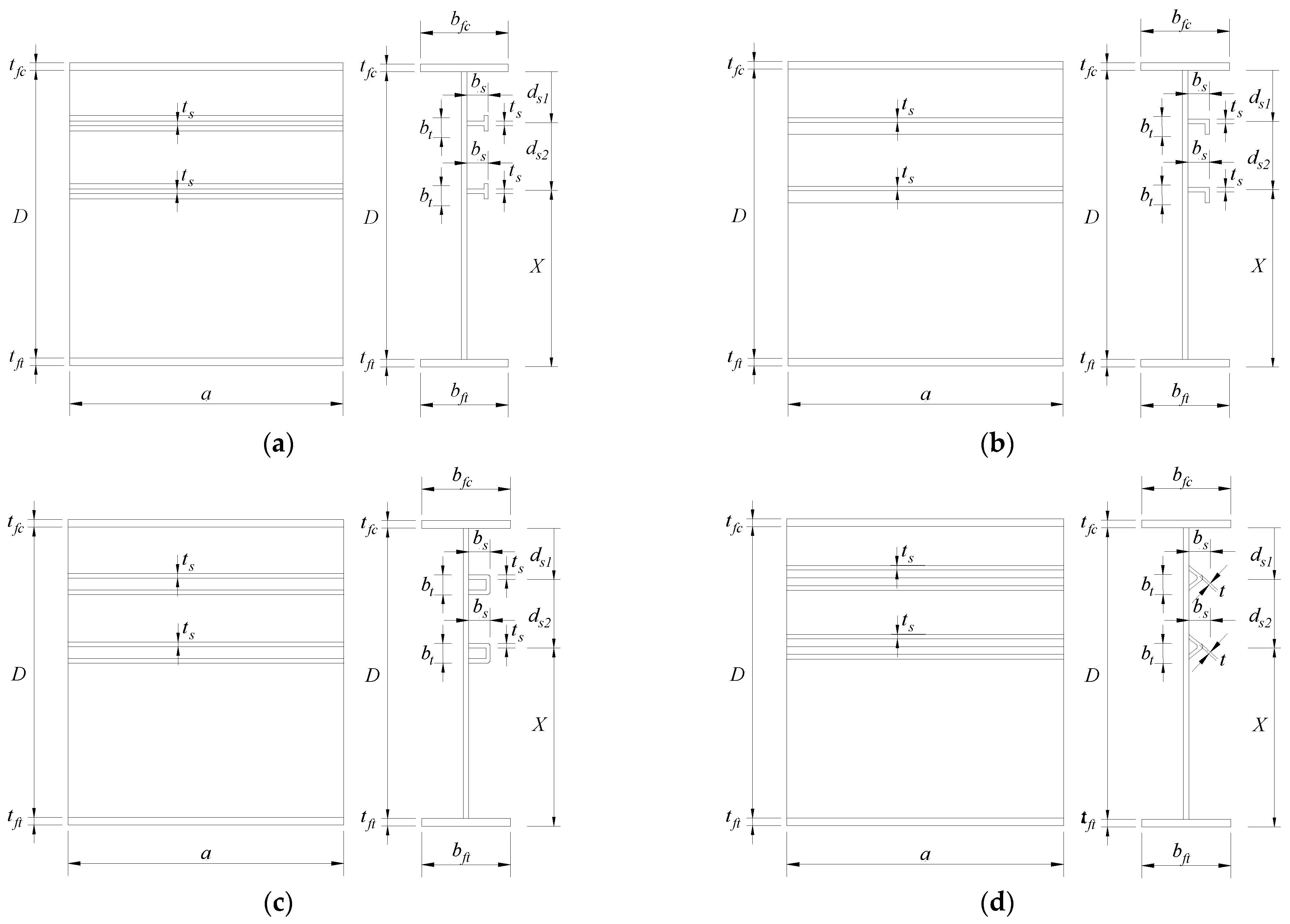
4. Finite Element Modeling

The bend-buckling behavior of a stiffened plate girder presented in Figure 2 was computed based on finite element (FE) analysis of the structure using ABAQUS commercial software [24]. In this work, FE models of the girder with two longitudinal stiffeners with open (T-shaped and L-shaped) and closed (triangular and rectangular) cross-sections are based on the FE model mentioned in [14,15,22,34]. For instance, all descriptions of geometric dimensions of the girder (except the dimensions of longitudinal stiffeners), material properties, and FE modeling procedure are consistent with those of model 2 reported in [14,15]. Particularly, the web depth was selected as 3.0 m, while the web thickness was 9.0 mm. The flange width and flange thickness were 600 mm and 54 mm, respectively. The length-to-depth ratio (panel aspect ratio) of the girder was chosen to be 1.0. All materials were considered to be in the elastic range with an elastic modulus of 210 GPa and a Poisson’s ratio of 0.3. The vertical edges of the girder web were assumed to be simply supported. All elements were simulated using 4-node shell elements S4R with a mesh size of 40 mm [14,15]. Figure 3 and Figure 4 display the loading and boundary conditions for all stiffener cross-section types. Based on these FE models developed and the procedure mentioned in Section 3.3, the optimum stiffener position of two longitudinal stiffeners with open and closed cross-sections will be investigated in Section 5 and Section 6 of this study. It is noted that, although the load distribution, which is specified in the Abaqus model, follows the linear shape which appears in Figure 3, in Figure 4, due to the notation followed in Abaqus/CAE interface, the length of the force vectors appears as fixed for visualization purposes.

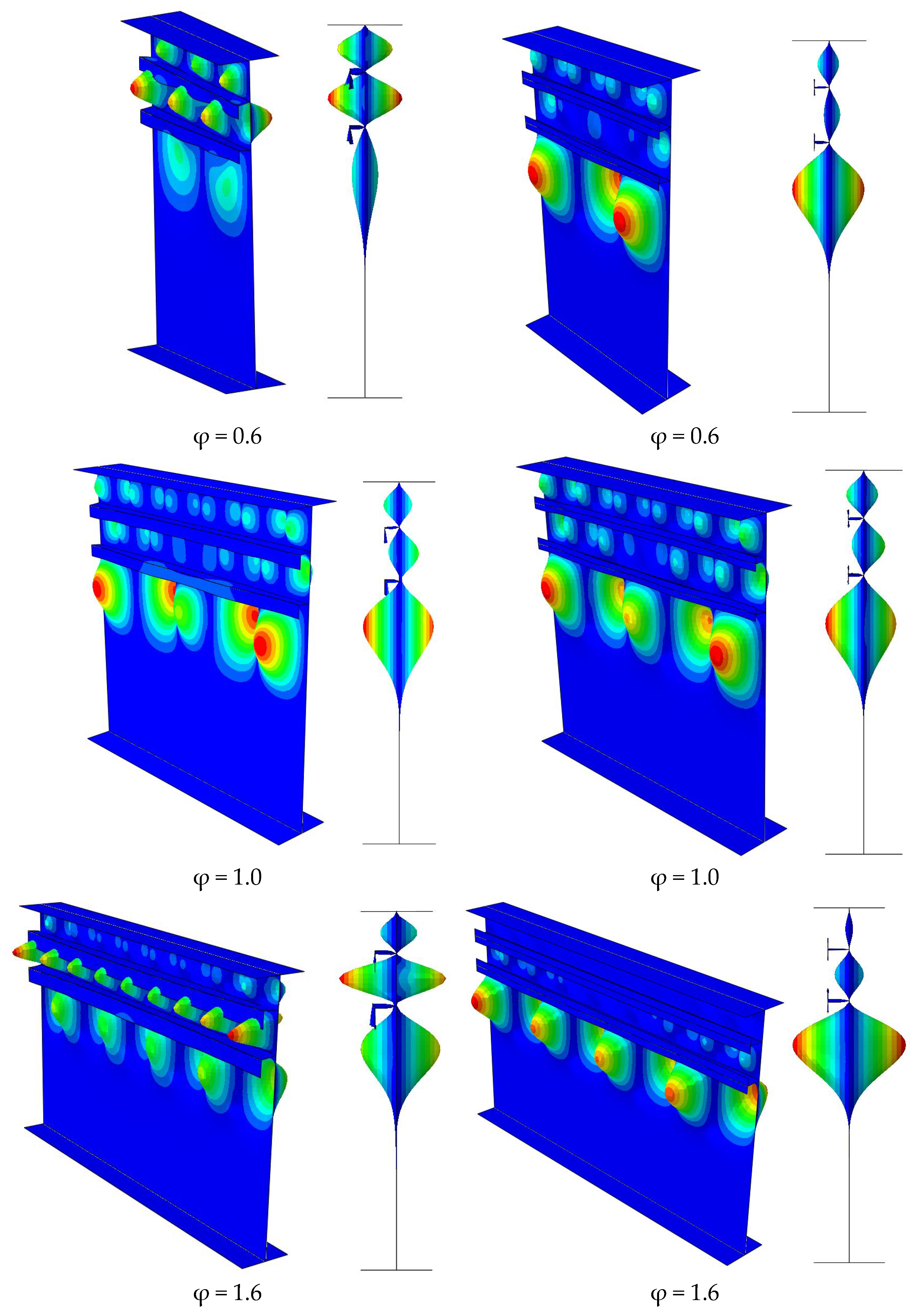
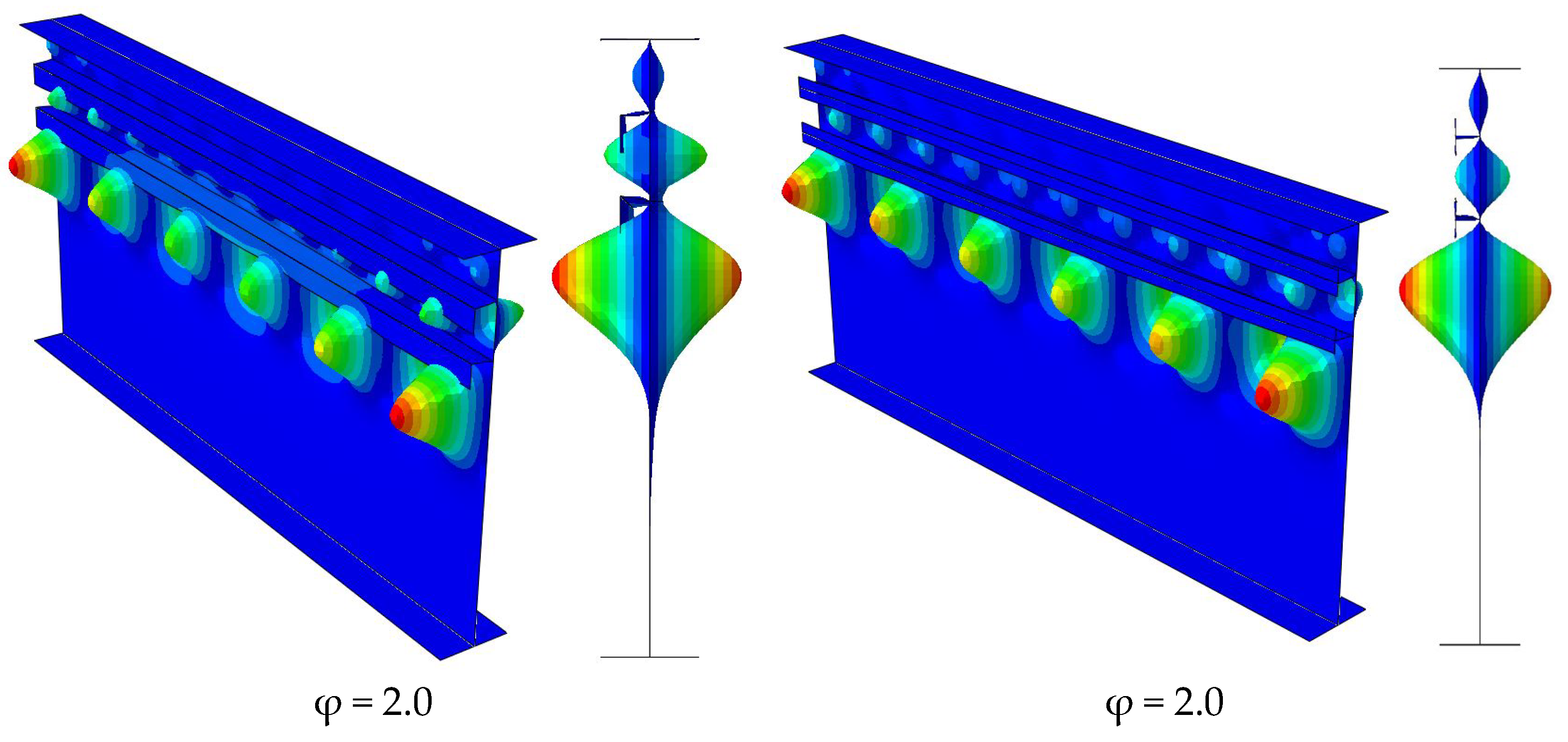
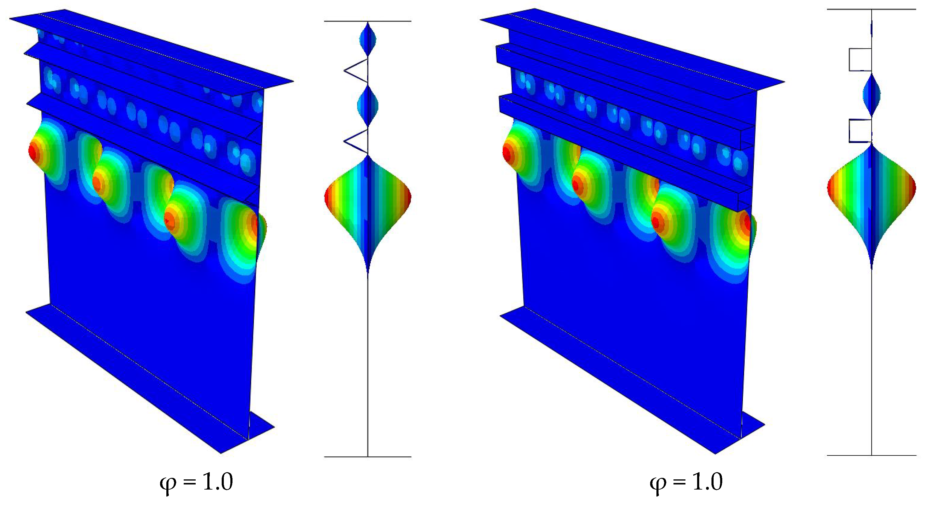
5. Optimum Location of 2 Stiffeners with Open Cross-Section Types

In this section, the optimization procedure presented in Section 3.3 is employed for finding the optimal positions of two longitudinal stiffeners with open cross-section types (T and L sections) along the web depth of the stiffened girder subjected to pure bending loading.
The optimum placement of two stiffeners having flat, T-shaped and L-shaped cross- sections is presented in Table 1, in which the results for the flat shape were taken from Kim et al. [15] for comparison. The aspect ratio of the panel (φ = a/D) was fixed as 1.0 and the slenderness ratio of girder web (D/tw) was fixed as 333 for all stiffener cross-section types. From Table 1, it can be observed that the optimal positions of longitudinal stiffeners 1 and 2 for both T-shaped and L-shaped cross-sections are at around 0.25Dc and 0.55 Dc, respectively. It is apparent that the optimum values are similar with those obtained for the flat stiffener cross-section type reported by Kim et al. [15]. In addition, it can be observed that the buckling coefficient, kb, of the stiffener with a T-shaped cross-section is slightly higher than that of the stiffener with an L-shaped cross-section. However, both stiffeners with T-shaped and L-shaped cross-sections yield much higher buckling coefficients compared with the flat cross-section. Therefore, using stiffeners with T-shaped or L-shaped cross-sections significantly enhances the bend-buckling strength of the stiffened plate girder compared to stiffeners with a flat cross-section. Figure 5 shows the convergence history for stiffeners with open cross-section shapes, while Figure 6 shows the mode shapes of the girders with stiffeners of T-shaped and L-shaped cross-section types obtained from the optimization procedure.
Table 2 discloses the effect of the panel aspect ratio on the optimal stiffener locations with the aspect ratios of 0.6, 1.0, 1.6, and 2.0. It can be seen that there is only a small effect of the panel aspect ratio on the optimal stiffener locations for both stiffener types. It was also observed that the buckling coefficients of the stiffeners corresponding to φ = 0.6 and φ = 1.0 were almost identical, while the buckling coefficients of the stiffeners corresponding to φ = 1.6 and φ = 2.0 were almost identical as well. The reason is because the flexural rigidify used for the stiffeners with φ = 1.6 and 2.0 is higher than that for the stiffeners with φ = 0.6 and 1.0.

6. Optimum Location of Two Stiffeners with Closed Cross-Section Types

This section examines the optimum placements of two longitudinal stiffeners with closed cross-section types consisting of triangular and rectangular shapes for a stiffened girder subjected to bending by performing the procedure presented in Section 3.3.
The optimal positions of two longitudinal stiffeners with rectangular and triangular cross-section types are indicated in Table 3 for different aspect ratios. It is seen from this table that the optimal stiffener positions for these cross-section types are similar regardless of the aspect ratio. The optimum placements of stiffeners 1 and 2 are at around 0.23Dc and 0.55Dc from the compression flange of the girder, respectively. These optimum values are slightly different from the optimum locations of stiffeners with open cross-section types. Therefore, it can be concluded that the optimum positions of two longitudinal stiffeners with open and closed cross-section configurations are quite similar. In addition, it can be observed from Table 3 that the bend-buckling coefficients of the stiffeners with triangular shape are about 5% higher than those with rectangular shape. The convergence histories obtained from the optimization procedure for stiffeners with triangular and rectangular cross-section shapes are presented in Figure 7, while the mode shapes of these stiffeners are illustrated in Figure 8. It is noted that the mode shapes obtained from these stiffener types are similar.

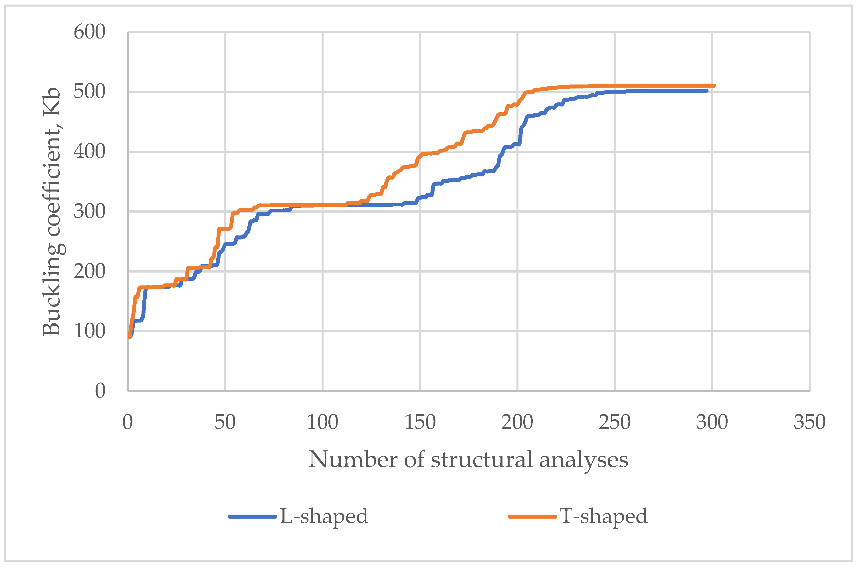
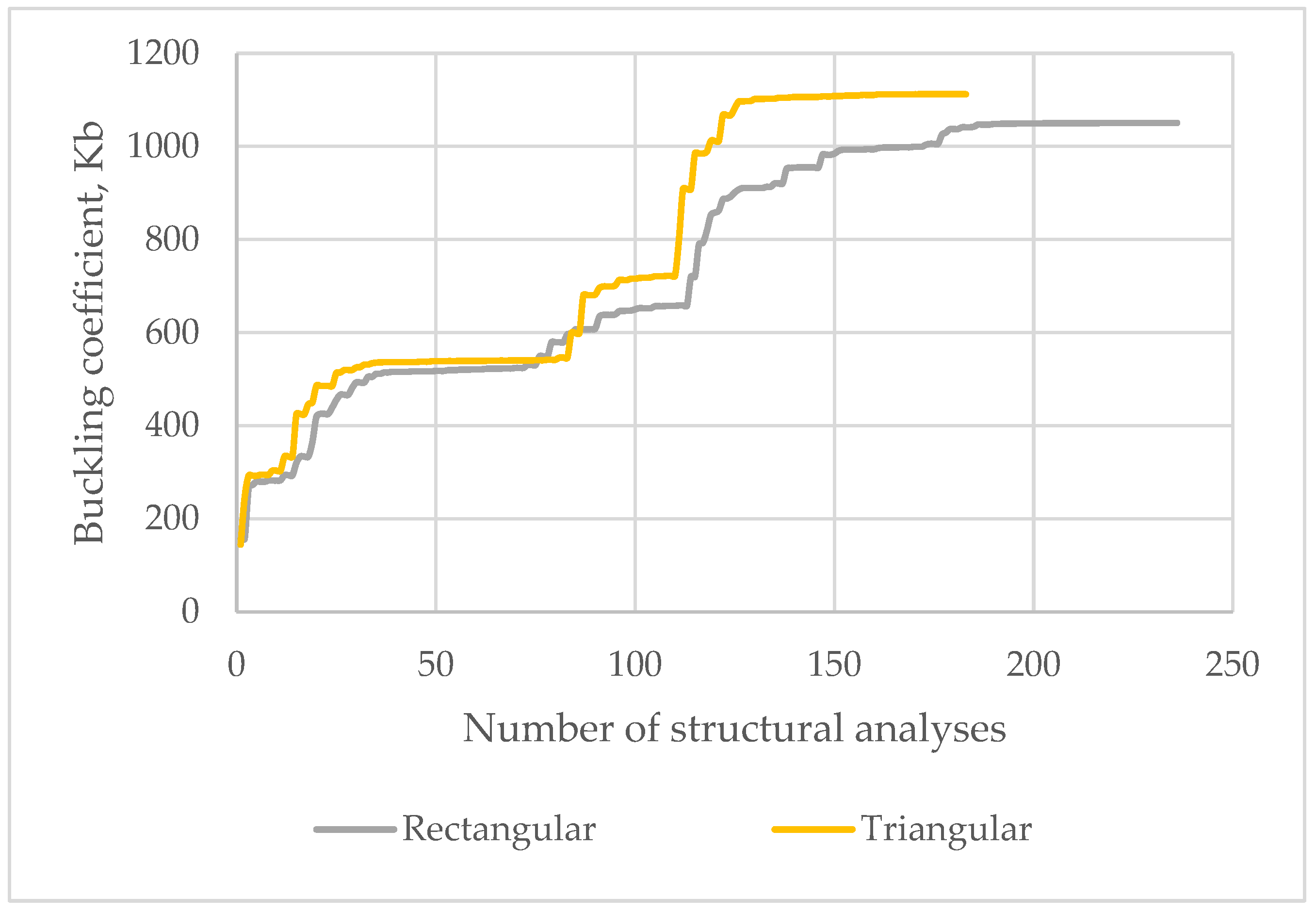
7. Comparison of the Efficiency of Longitudinal Stiffener Types

This section compares the efficiency of two longitudinal stiffeners with various cross-section shapes in terms of buckling coefficient and minimum web thickness of the stiffened girder. Regarding the buckling coefficient, Figure 9 presents a comparison of the buckling coefficient for two longitudinal stiffeners with flat, T, L, rectangular, and triangular cross-section shapes with respect to a panel aspect ratio of 1. It can be observed that the buckling coefficients of stiffeners with closed section shapes are significantly higher than those with open cross-section shapes. In particular, the triangular shape provides the highest buckling coefficient, while the flat shape gives the lowest buckling coefficient.
Regarding the minimum web thickness of the stiffened girder, the limit of the slenderness ratio of stiffened webs should satisfy the requirements mentioned in AASHTO LRFD [17] as follows:
D t w 0.95 E k b F y
where
kb represents the bend-buckling coefficient of the stiffened girder;
Fy stands for the steel yield strength;
Fy is assumed to be 315 MPa;
E is elastic modulus, where E = 210 GPa.
From Equation (13), the minimum thickness of the stiffened web is computed as follows:
t w D 0.95 E k b F y
From Equation (17), a comparison of the minimum thicknesses of the girder web computed for various stiffener shapes is given in Table 4. It is observed in Table 4 that the flat stiffener needs the highest minimum web thickness, while the triangular stiffener requires the lowest minimum web thickness among all stiffener types considered. It is noteworthy that the required web thickness of the girder web reinforced by two stiffeners with closed cross-section shapes is significantly reduced compared to those reinforced by two stiffeners with open cross-section shapes. In particular, when the web girder is reinforced by two stiffeners with a triangular section shape, the required web thickness decreases by at least 37.26% compared with the case in which the web is reinforced by two stiffeners with a flat cross-section shape.

8. Conclusions

In this work, the optimum positions of two longitudinal stiffeners with different cross-section shapes placed at the web of stiffened girders under bending are examined through an optimization procedure performed by coupling Abaqus and Matlab through the Abaqus2Matlab toolbox. Based on the optimization results, the optimum locations of two longitudinal stiffeners with open and closed cross-section types are obtained. An advantage of the proposed methodology is that it simulates the structural optimization problem with a robust numerical procedure which combines FEA and optimization, and it proves to be able to yield meaningful results for all structural configuration cases with an acceptable accuracy and a reduced computational effort. Some conclusions can be drawn as follows:
-
The optimum positions of the stiffeners with open cross-section shapes (T- and L-shaped) are around 0.25Dc and 0.55Dc, which are similar to the optimum location of the flat stiffener.
-
The optimum positions of the stiffeners with closed cross-section shapes (triangular and rectangular shapes) are around 0.23Dc and 0.54Dc, which are slightly different to the stiffeners with open cross-sections.
-
The bend-buckling coefficient of the stiffened girder with stiffeners with a triangular cross-section shape is highest, while that with a flat cross-section shape is lowest in all considered stiffener types.
-
The required web thickness of the girder web reinforced by two stiffeners with closed section shapes is remarkably reduced compared with those reinforced by two stiffeners with open cross-section shapes.
The main objective of this study is to investigate the effect of the stiffener location and shape on the buckling load and configuration of steel plate girders reinforced by two longitudinal stiffeners due to bending loading. Maximizing the buckling coefficient leads to the optimum design, since this maximizes the load capacity in each structural configuration of the steel plate girder. The optimization procedure that is implemented in this study has led to the discovery of optimum configurations which maximize the buckling load capacity. Therefore, the optimum locations of the two stiffeners proposed in this study should be taken into account for maximizing the safety of the structure, as should other constraints in construction. A major observation is that stiffeners with triangular cross-sections lead to the highest buckling coefficient compared with other cross-section shapes. Apart from this, it is proven in this study that a suitable selection of stiffener cross-section type and location can lead to a substantial construction cost reduction compared to the usual state of practice designs, since the web thickness can be reduced by as much as 37.26%.
Future work could address issues such as investigating the effect on the buckling load capacity of the plate girder of various loading types (shear loading, patch loading, biaxial bending, etc.), structural constraints (e.g., presence of bolts at the web or flanges), stiffener orientations (vertical or oblique), and cutouts (circular or rectangular) at the web body.

Author Contributions

Conceptualization, Y.P.; methodology, Z.K.; software, G.P.; validation, Z.K.; formal analysis, Y.P.; investigation, Q.-V.V.; resources, B.H.D.; data curation, T.-S.C.; writing—original draft preparation, G.P.; writing—review and editing, H.-H.N.; visualization, B.H.D.; supervision, Q.-V.V.; project administration, Q.-V.V.; funding acquisition, Q.-V.V. All authors have read and agreed to the published version of the manuscript.

Funding

This research was funded by Vietnam National Foundation for Science and Technology Development (NAFOSTED) under grant number 107.01-2019.322.

Data Availability Statement

Data will be available upon reasonable request.

Conflicts of Interest

The authors declare no conflict of interest.

References

  1. Haffar, M.Z.; Kövesdi, B.; Adany, S. Buckling of compressed plates with closed-section longitudinal stiffeners: Two new mathematical models for resistance prediction. Structures 2021, 33, 3526–3539. [Google Scholar] [CrossRef]
  2. Kovesdi, B.; Haffar, M.; Adany, S. Buckling resistance of longitudinally stiffened plates: Eurocode-based design for col-umn-like and interactive behavior of plates with closed-section stiffeners. Thin-Walled Struct. 2021, 159, 107266. [Google Scholar] [CrossRef]
  3. Loaiza, N.; Graciano, C.; Casanova, E. Web slenderness for longitudinally stiffened I-girders subjected to patch loading. J. Constr. Steel Res. 2019, 162, 105737. [Google Scholar] [CrossRef]
  4. Demari, F.E.; Mezzomo, G.P.; Pravia, Z.M.C. Numerical study of slender I-girders with one longitudinal stiffener under patch loading. J. Constr. Steel Res. 2020, 167, 105964. [Google Scholar] [CrossRef]
  5. Truong, V.-H.; Papazafeiropoulos, G.; Vu, Q.-V.; Pham, V.-T.; Kong, Z. Predicting the patch load resistance of stiffened plate girders using machine learning algorithms. Ocean Eng. 2021, 240, 109886. [Google Scholar] [CrossRef]
  6. Truong, V.-H.; Papazafeiropoulos, G.; Pham, V.-T.; Vu, Q.-V. Effect of multiple longitudinal stiffeners on ultimate strength of steel plate girders. Structures 2019, 22, 366–382. [Google Scholar] [CrossRef]
  7. Chen, Z.; Yuan, H. Local buckling behaviour of longitudinally stiffened stainless steel plate girders under combined bending and shear. Thin-Walled Struct. 2023, 184, 110541. [Google Scholar] [CrossRef]
  8. Azhari, M.; Bradford, M. Local buckling of I-section beams with longitudinal web stiffeners. Thin-Walled Struct. 1993, 15, 1–13. [Google Scholar] [CrossRef]
  9. Alinia, M.; Moosavi, S. A parametric study on the longitudinal stiffeners of web panels. Thin-Walled Struct. 2008, 46, 1213–1223. [Google Scholar] [CrossRef]
  10. Vu, Q.-V.; Papazafeiropoulos, G.; Graciano, C.; Kim, S.-E. Optimum linear buckling analysis of longitudinally multi-stiffened steel plates subjected to combined bending and shear. Thin-Walled Struct. 2018, 136, 235–245. [Google Scholar] [CrossRef]
  11. Vu, Q.-V.; Truong, V.-H.; Papazafeiropoulos, G.; Graciano, C.; Kim, S.-E. Bend-buckling strength of steel plates with multiple longitudinal stiffeners. J. Constr. Steel Res. 2019, 158, 41–52. [Google Scholar] [CrossRef]
  12. Elbanna, A.; Ramadan, H.; Mourad, S. Buckling enhancement of longitudinally and vertically stiffened plate girders. J. Eng. Appl. Sci. 2014, 61, 351–370. [Google Scholar]
  13. HKim, S.; Park, Y.; Kim, B.; Kim, K. Numerical investigation of buckling strength of longitudinally stiffened web of plate girders subjected to bending. Struct. Eng. Mech. 2018, 65, 141–154. [Google Scholar]
  14. Hoàn, P.; Trung, P.; Vi, V. Nghiên cứu xác định vị trí tối ưu của sườn tăng cường dọc của dầm cầu thép chịu uốn. Tạp chí Khoa học Công nghệ Xây dựng. NUCE 2020, 14, 29–38. [Google Scholar]
  15. Kim, S.-E.; Papazafeiropoulos, G.; Graciano, C.; Truong, V.-H.; Do, Q.T.; Kong, Z.; Vu, Q.-V. Optimal design of longitudinal stiffeners of unsymmetric plate girders subjected to pure bending. Ocean Eng. 2021, 221, 108374. [Google Scholar] [CrossRef]
  16. Cho, E.-Y.; Shin, D.-K. Elastic web bend-buckling analysis of longitudinally stiffened I-section girders. Int. J. Steel Struct. 2011, 11, 297–313. [Google Scholar] [CrossRef]
  17. AASHTO. AASHTO LRFD Bridge Design Specifications, 7th ed.; American Association of State Highway and Transportation Officials: Washington, DC, USA, 2014. [Google Scholar]
  18. Rockey, K.; Cook, I. Optimum reinforcement by two longitudinal stiffeners of a plate subjected to pure bending. Int. J. Solids Struct. 1965, 1, 79–92. [Google Scholar] [CrossRef]
  19. Rockey, K.; Cook, I. The buckling under pure bending of a plate girder reinforced by multiple longitudinal stiffeners. Int. J. Solids Struct. 1965, 1, 147–156. [Google Scholar] [CrossRef]
  20. Kim, B.J.; Park, Y.; Kim, K.; Choi, B. Web bend-buckling strength of plate girders with two longitudinal web stiffeners. Struct. Eng. Mech. 2019, 69, 383–397. [Google Scholar]
  21. Maiorana, E.; Pellegrino, C.; Modena, C. Influence of longitudinal stiffeners on elastic stability of girder webs. J. Constr. Steel Res. 2010, 67, 51–64. [Google Scholar] [CrossRef]
  22. Papazafeiropoulos, G.; Vu, Q.-V.; Nguyen, V.-S.; Truong, V.-H. Optimum location of a single longitudinal stiffener with various cross-section shapes of steel plate girders under bending loading. J. Sci. Technol. Civ. Eng. (STCE)—NUCE 2022, 16, 65–75. [Google Scholar] [CrossRef]
  23. Papazafeiropoulos, G.; Muñiz-Calvente, M.; Martínez-Pañeda, E. Abaqus2Matlab: A suitable tool for finite element post-processing. Adv. Eng. Softw. 2017, 105, 9–16. [Google Scholar] [CrossRef]
  24. ABAQUS. Analysis User’s Manual, Version 6.14; Dassault Systems: Los Angeles, CA, USA, 2014.
  25. MathWorks, Inc. MATLAB R2017b; MathWorks, Inc.: Natick, MA, USA, 2017. [Google Scholar]
  26. Frank, K.H.; Helwig, T.A. Buckling of webs in unsymmetric plate girders. Eng. J. Second Quart. 1995, 32, 43–53. [Google Scholar]
  27. CEN. EN 1993-1-5; Eurocode 3: Design of Steel Structures-Part 1-5: Plated Structural Elements. European Committee for Standardization: Brussels, Belgium, 2006.
  28. Byrd, R.H.; Gilbert, J.C.; Nocedal, J. A trust region method based on interior point techniques for nonlinear programming. Math. Program. 2000, 89, 149–185. [Google Scholar] [CrossRef]
  29. Byrd, R.H.; Hribar, M.E.; Nocedal, J. An Interior Point Algorithm for Large-Scale Nonlinear Programming. SIAM J. Optim. 1999, 9, 877–900. [Google Scholar] [CrossRef]
  30. Waltz, R.; Morales, J.; Nocedal, J.; Orban, D. An interior algorithm for nonlinear optimization that combines line search and trust region steps. Math. Prograhm. 2006, 107, 391–408. [Google Scholar] [CrossRef]
  31. Pham, V.T.; Vu, Q.V.; Papazafeiropoulos, G.; Ngo, V.T. Efficiency of Abaqus2Matlab toolbox for structural optimization problems. IOP Conf. Ser. Mater. Sci. Eng. 2020, 869, 022025. [Google Scholar] [CrossRef]
  32. Ghorashi, M.; Askarian, A.; Gashtasby, M. Optimal design of stiffened plates for buckling under in-plane forces and bending moments. In Proceedings of the Eighth International Conference on the Application of Artificial Intelligence to Civil and Structural Engineering Computing, Stirling, UK, 19–21 September 2001; pp. 83–84. [Google Scholar]
  33. Silva, D.A.B.; Filho, J.O.F.; Barreto, R. Numerical study for optimization of the buckling behavior of longitudinally stiffened plates under pure bending. In Proceedings of the 1st International Congress on Structural Integrity and Maintenance—SIM 2021, Online, 8–9 April 2021. [Google Scholar]
  34. Papazafeiropoulos, G.; Vu, Q.-V.; Truong, V.-H.; Luong, M.-C.; Pham, V.-T. Prediction of buckling coefficient of stiffened plate girders using deep learning algorithm. Lect. Notes Civ. Eng. 2019, 54, 1143–1148. [Google Scholar] [CrossRef]
Figure 1. The optimization procedure flowchart [10,11].
Metals 13 00323 g001
Figure 2. Geometric dimensions of stiffened plate girders with various stiffener cross-section shapes. (a) T-shaped; (b) L-shaped; (c) Rectangular-shaped; (d) Triangular-shaped.
Metals 13 00323 g002
Figure 3. Loading and boundary conditions for various plate girder configurations: (a) T section, (b) L section, (c) triangular section, (d) rectangular section.
Metals 13 00323 g003aMetals 13 00323 g003b
Figure 4. Loading and boundary conditions for various plate girder configurations in Abaqus: (a) T section, (b) L section, (c) triangular section, (d) rectangular section.
Metals 13 00323 g004
Figure 5. Convergence history for stiffeners with open cross-section shapes.
Metals 13 00323 g005
Figure 6. Buckling mode shapes of the stiffened girder with T-shaped and L-shaped stiffeners.
Metals 13 00323 g006aMetals 13 00323 g006b
Figure 7. Convergence history for stiffeners with closed cross-section shapes.
Metals 13 00323 g007
Figure 8. Bend-buckling mode shapes of a stiffened girder with triangular and rectangular stiffener cross-sections.
Metals 13 00323 g008aMetals 13 00323 g008b
Figure 9. Comparison of buckling coefficient for two longitudinal stiffeners with various cross-section shapes (φ = 1.0).
Metals 13 00323 g009
Table 1. Optimal values for two longitudinal stiffeners for both cross-section types.
Stiffener Typeφds1/Dcds2/DckbNote
Flat-shaped1.00.2440.566437.02[15]
T-shaped1.00.250.55501.62Present study
L-shaped1.00.250.55500.25Present study
Table 2. Effect of panel aspect ratio on the optimum stiffener locations.
φStiffener Typeds1/Dcds2/Dckb
0.6T-shaped0.250.55501.48
L-shaped0.250.55500.1
1.0T-shaped0.250.55501.62
L-shaped0.250.55500.25
1.6T-shaped0.240.53582.76
L-shaped0.240.53578.59
2.0T-shaped0.240.53582.96
L-shaped0.240.53579.32
Table 3. Optimum results for the longitudinal stiffeners with closed cross-section types.
φStiffener Typesds1/Dcds2/Dckb
0.6Triangular0.230.551109.33
Rectangular0.230.541049.47
1.0Triangular0.230.551112.28
Rectangular0.230.541050.66
Table 4. Comparison of minimum stiffened web thickness.
Stiffener TypeD (mm)kbtmin (mm)
Flat-shaped 3000437.025.85
T-shaped3000501.625.46
L-shaped3000500.255.47
Triangular30001112.283.67
Rectangular30001050.663.77
Disclaimer/Publisher’s Note: The statements, opinions and data contained in all publications are solely those of the individual author(s) and contributor(s) and not of MDPI and/or the editor(s). MDPI and/or the editor(s) disclaim responsibility for any injury to people or property resulting from any ideas, methods, instructions or products referred to in the content.

