Article

First-Principles Calculation and Kink-Dislocation Dynamics Simulation on Dislocation Plasticity in TiZr-Based Concentrated Solid-Solution Alloys

1
College of Materials Science and Engineering, Central South University, Changsha 410017, China
2
Department of Mechanical Engineering, The Hong Kong Polytechnic University, Hung Hom, Kowloon 999077, Hong Kong
*
Author to whom correspondence should be addressed.
Metals 2023, 13(2), 351; https://doi.org/10.3390/met13020351
Submission received: 20 December 2022 / Revised: 25 January 2023 / Accepted: 5 February 2023 / Published: 9 February 2023
(This article belongs to the Special Issue Microstructure, Properties and Modelling of High-Entropy Alloys)

Abstract

:
The dislocation plasticity of TiZr-based hexagonal close-packed (HCP) concentrated solid-solution alloys (CSAs) is investigated using a multiscale simulation approach combining the first-principles calculation and Frenkel–Kontonova kink-dislocation model. The first-principles calculation reveals that dislocation-mediated slip is significantly enhanced by the additions of Y and Sc in TiZrHf CSAs. The dislocation kinetics is simulated using the kink-dislocation model at mesoscopic scales, and the predicted mechanical strength of CSA is found to be consistent with experimental results. In addition to predicting the mechanical properties of CSAs accurately, the multiscale simulation approach elucidates the deformation mechanisms in CSAs at atomic scales, suggesting that the approach is robust in modeling the dislocation plasticity of CSAs.

1. Introduction

Single-phase concentrated solid-solution alloys (CSAs) are composed of two or more principal elements, where atoms are randomly situated on specified lattice sites. The CSAs with four or more constituent alloy elements, so-called high-entropy alloys (HEAs), have attracted much attention because of their exceptional mechanical properties [1,2,3]. It has been found that HEAs with body-centered cubic (BCC) structures usually exhibit high mechanical strength but possess limited plasticity, while those with face-centered cubic (FCC) structures have relatively low strength but usually show fine plasticity [4,5,6,7,8,9]. Thus, the development of CSAs with high strength and enhanced ductility has been widely explored for scientific interests and engineering applications. Recently, a strategy of metastable transformation-induced plasticity was introduced to CSAs. The obtained alloys consisted of multiple phases, which exhibited improved strength and ductility.
Although most CSAs reported to date have focused on those with FCC, BCC, or FCC-BCC mixed structure, there is limited information on CSAs comprising solid solutions with hexagonal close-packed (HCP) structures. The reason is probably that HCP structures are stable at low temperatures, while they exhibit a tendency to transform to either BCC or FCC structures at elevated temperatures. It was suggested [9] that the difficulty in forming HCP CSAs is owing to the fact that most elements found in the periodic table prefer a BCC or FCC structure in nature; although some elements possess a stable HCP structure below their melting points, such as Cd, Mg, Os, Re, Ru, Tc, and Zn, they can transform to other structures when the temperature increases beyond the melting points [9]. For instance, Be, Sc, Ti, Zr, and Hf can possess BCC structure, and Co can possess FCC structure at high temperatures [9]. Nonetheless, with the help of rapidly developed materials processing technology and computational materials sciences, several CSAs with HCP structures have been proposed [9,10,11,12,13,14,15]. Chen et al. developed an amorphous structure with HCP elements in equimolar BeCoMgTi alloy by means of mechanical alloying [10]. However, the obtained samples did not show homogenous HCP structures. CSAs with HCP structures were also reported in those comprising Co, Hf, Ti, and Zr constituent alloy elements. Youssef et al. reported that Al20Li20Mg10Sc20Ti30 (at.%) high-entropy alloy (HEA) powders with a stable HCP structure [11] were obtained through a mechanical synthesis route. Particularly, nearly single-phase HCP structures in CSAs with equiatomic ratios that consisted of rare earth elements were confirmed, such as YGdTbDyLu, GdTbDyTmLu, and HoDyYGdTb [12,13,14]. Based on a systematic study [15] on binary equilibrium diagrams of HCP alloys, it was obtained that the CoOsReRu with equilibrium compositions may also form HCP solid solutions. In particular, TiZr-based HCP CSAs developed recently are of significant interest. Huang et al. studied the effect of Sc and Y additions on the microstructure and properties of HCP-structured TiZrHf-based HEAs [16]. Rogal et al. investigated the microstructures and mechanical properties of a Hf25Sc25Ti25Zr25 equiatomic alloy with an HCP structure using experimental and theoretical methods [17].
It is well known that in conventional alloys without chemical disorder, the mechanical properties are closely related to dislocation plasticity. However, the knowledge of the influences of chemical disorder on dislocation activities in CSAs remains incomplete, especially in those with HCP structures. Experimental observations have revealed that the mechanical strength of CSAs is closely related to the deformation mechanisms different from dislocation glides in conventional metals and alloys [18,19,20]. Basically, the deformation mechanism and dislocation activity in crystalline materials are highly dependent on their stacking-fault energies (SFEs) [21,22,23], which characterize the energy barriers that significantly affect the mobility of dislocations at atomic scales. Thus, the generalized stacking fault energy (GSFE) curve determined by the first-principles calculation has been utilized to investigate the deformation mechanisms in CSAs [24,25,26]. However, the understanding of the dislocation plasticity in CSAs, as reflected by the dislocation dynamics at mesoscopic scales, is still rather limited.
In this work, taking TiZr-based HCP CSAs as examples, the dislocation plasticity in CSAs is investigated using multiscale simulation. Firstly, first-principles calculations are employed to determine the GSFE curve, elucidating the phase stability and deformation mechanisms of CSAs. Consequently, energy barriers for the formations of stacking faults, twin faults, and FCC faults are determined from the generalized planar fault energy (GPFE) curve. Compared to other methods of the first-principles calculation, the advantage of GPFE curves is the analysis of deformation mechanisms, including dislocation-mediated slips, deformation twinning, and HCP-to-FCC transformation in the same model system, whose energetics can be explicitly compared. Based on the obtained results, the effects of alloying elements on the deformation mechanisms of TiZr-based HCP CSAs are discussed in detail. Secondly, the kink-dislocation model, with its parameters determined by the first-principles calculations, is employed to simulate dislocation plasticity at mesoscopic scales.
The multiscale simulation is intended to solve the aforementioned issues related to the formation of HCP HEAs as well as their unique mechanical properties. First, the stability of TiZr-based HCP CSAs is analyzed against alloying elements of Y, Sc, and Hf, which can be quantitatively measured based on free energy, lattice distortion, and atomic size mismatch. Second, based on the deformation mechanisms as revealed by the GPFE curves, the differences in mechanical properties of HCP CSAs as measured from experiments are explained. Third, the mechanical properties of CSAs are quantitatively predicted by the kink-dislocation dynamics. Therefore, for the first time, the multiscale simulation approach can elucidate the deformation mechanisms in CSAs in addition to predicting their mechanical properties well.

2. Methodology

2.1. First-Principles Calculation

The HCP CSAs are studied using an orthorhombic supercell with lattice vectors aligned in the crystallographic directions of [−12−10], [10−10], and [0001]. The special quasi-random structure (SQS) technique [27] implemented in the Alloy Theoretic Automated Toolkit (ATAT) [28] is applied to simulate the chemical disorder of CSAs, and the supercells of Ti120Zr120, Ti80Zr80Hf80, Ti60Zr60Hf60Sc60, Ti60Zr60Hf60Y60, and Ti48Zr48Hf48Sc48Y48, as shown in Figure 1, are used for the first-principles calculations. The stacking sequence of the (0001) planes in the supercells is assigned as BABABABABABABABABABA. The relaxation of supercells is performed by fixing the orthorhombic lattice structure, while the lengths of lattice vectors are varied to minimize the interatomic Hellmann–Feynman forces. First-principles computations are performed using the Vienna ab initio Simulation Package (VASP) codes [29,30,31,32], and generalized gradient approximation (GGA) is used for exchange-correlation functionals [33,34]. The plane-wave energy cutoff is set to 350 eV [32], and a gamma-centered k-point mesh of 2 × 3 × 1 generated using the Monkhorst–Pack algorithm is employed in the calculations [35]. The tolerances of energy and force are set to 1.0 × 10⁻⁴ eV/atom and −2.0 × 10⁻² eV/Å, respectively.
The slips of partial dislocations can lead to different deformation mechanisms in the alloys, and two types of deformation mechanisms, i.e., deformation twinning and HCP-to-FCC transformation, are investigated in this study. The deformation twinning occurs by passing the partials on adjacent slip planes, and consequently passing the partials on every second slip plane can result in the HCP-to-FCC transformation [36]. In order to understand the deformation processes in TiZr-based HCP CSAs, the GPFE curves or the energetics of passing a leading partial on the slip plane, a trailing partial on the nearest-neighbor slip plane, and a trailing partial on the next-nearest-neighbor slip plane are investigated. The planar fault is introduced by shifting one part of the supercell with respect to the other part along a specific direction. As an example, the supercell of Ti60Zr60Hf60Sc60 (Figure 1c) is selected to demonstrate the deformation process. We firstly move atoms in the 10th–20th layers of the supercell along [10−10] direction with a distance of the Burgers vector of the partial dislocation bp = a/3 [10−10], and the stacking sequence was changed into BABABABABCACACACACAC (Figure 1(c-1)), resulting in a system with two I2 intrinsic stacking faults. Based on the obtained supercell with I2 faults, moving atoms in the 11th–19th or the 12th–18th layers along [01−10] or [−1100] directions can lead to the supercell with twin fault or FCC fault, where the stacking sequence is denoted as BABABABABCBABABABABC (Figure 1(c-2)) or BABABABABCABCBCBCBAC (Figure 1(c-3)), respectively.

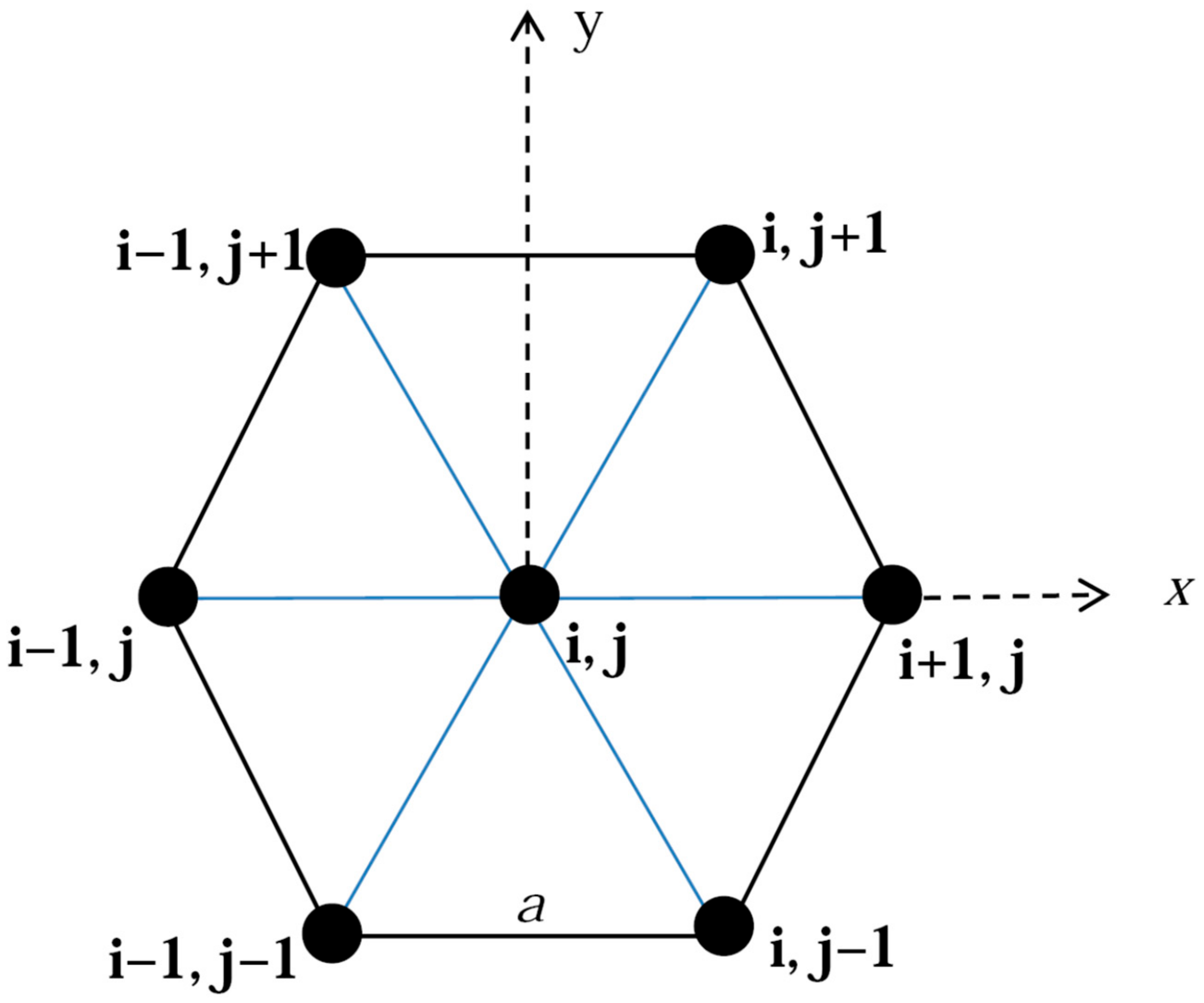
2.2. Simulation of Dislocation Kinetics by a Kink-Dislocation Model

The simulation of dislocation dynamics at a slip plane is carried out using a two-dimensional (2D) Frenkel–Kontorova kink-dislocation model [37], which was first proposed by Lomdahl and Srolovitz [38]. As shown in Figure 2, the displacements of atoms located at the 2D hexagonal lattice sites (i, j) are denoted as uij = (ui,j, vi,j)a, which describes the positions of a dislocation line lying on the (0001) slip plane. The equations of motion of the dislocation line can be written as [39]
2 u i , j t 2 = u i , j + 1 + u i , j 1 + u i 1 , j + 1 + u i 1 , j 1 + u i + 1 , j + u i 1 , j 6 u i , j + u i , j u i , j + 1 1 / 2 Δ 1 + u i , j u i , j 1 1 / 2 Δ 2 + u i , j u i 1 , j + 1 + 1 / 2 Δ 3 + u i , j u i 1 , j 1 + 1 / 2 Δ 4 + u i , j u i + 1 , j 1 Δ 5 + u i , j u i 1 , j + 1 Δ 6 V P x f x
2 v i , j t 2 = v i , j + 1 + v i , j 1 + v i 1 , j + 1 + v i 1 , j 1 + v i , + 1 j + v i 1 , j 6 v i , j + v i , j v i , j + 1 3 / 2 Δ 1 + v i , j v i , j 1 3 / 2 Δ 2 + v i , j v i 1 , j + 1 + 3 / 2 Δ 3 + v i , j v i 1 , j 1 + 3 / 2 Δ 4 + v i , j v i + 1 , j Δ 5 + v i , j v i 1 , j Δ 6 V P y f y
where f = (fx, fy) is the force applied on the dislocation line and Vp is the Peierls potential, and
V p = 2 V 0 { 3 cos ( 4 π 3 u i , j ) cos [ 2 π 3 ( u i , j + 3 v i , j ) ] cos [ 2 π 3 ( u i , j 3 v i , j ) ] } / G b , Δ 1 = ( u i , j u i , j + 1 1 2 ) 2 + ( v i , j v i , j + 1 3 2 ) 2 , Δ 2 = ( u i , j u i , j 1 1 2 ) 2 + ( v i , j v i , j 1 3 2 ) 2 , Δ 3 = ( u i , j u i 1 , j + 1 + 1 2 ) 2 + ( v i , j v i 1 , j + 1 3 2 ) 2 , Δ 4 = ( u i , j u i 1 , j 1 + 1 2 ) 2 + ( v i , j v i 1 , j 1 + 3 2 ) 2 , Δ 5 = ( u i , j u i + 1 , j 1 ) 2 + ( v i , j v i + 1 , j ) 2 , Δ 6 = ( u i , j u i 1 , j + 1 ) 2 + ( v i , j v i 1 , j ) 2 ,
where b is the Burgers vector, G is the shear modulus, and V0 is the energy barrier for the activation of dislocation kinks.

3. Results and Discussion

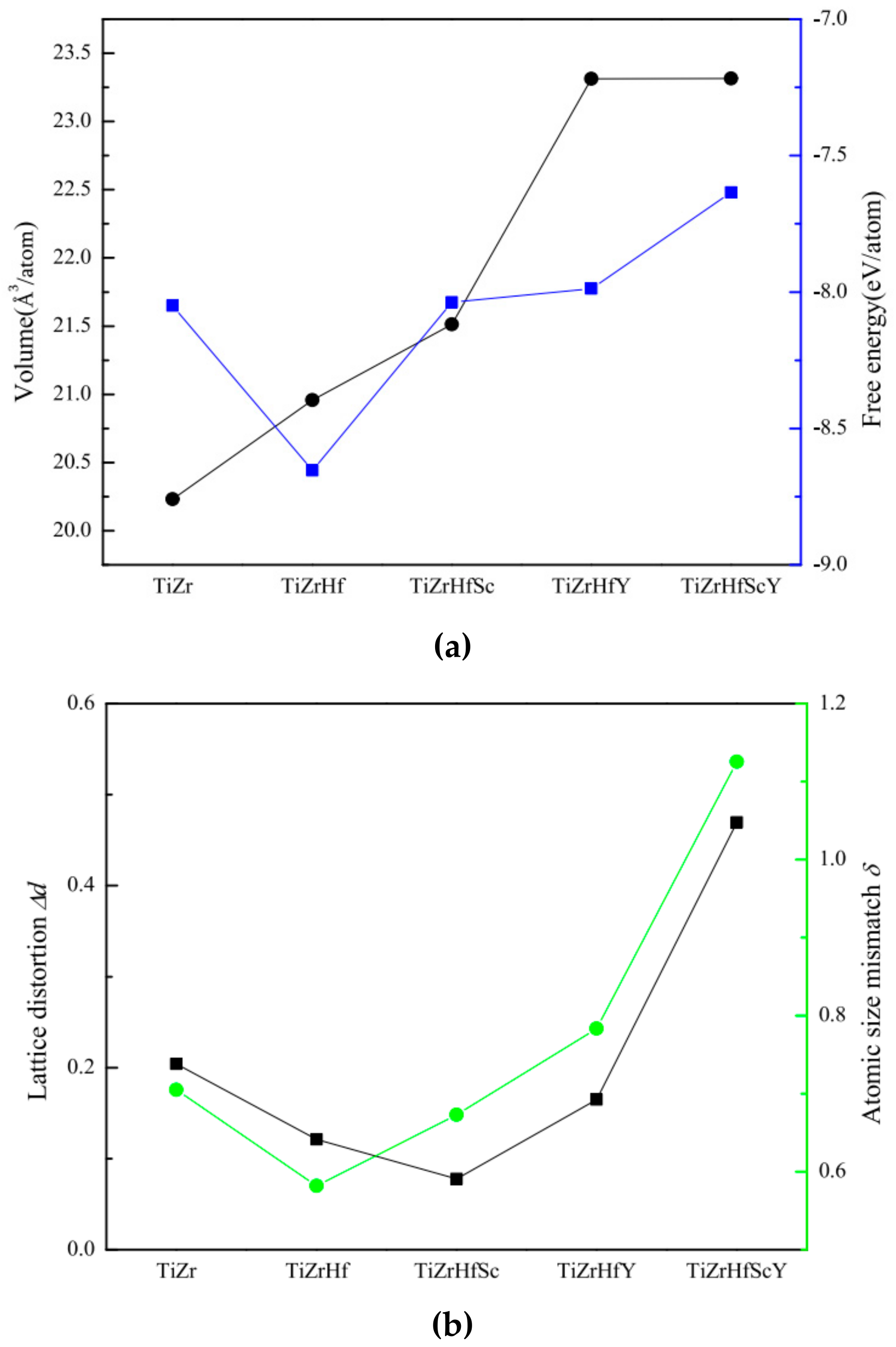
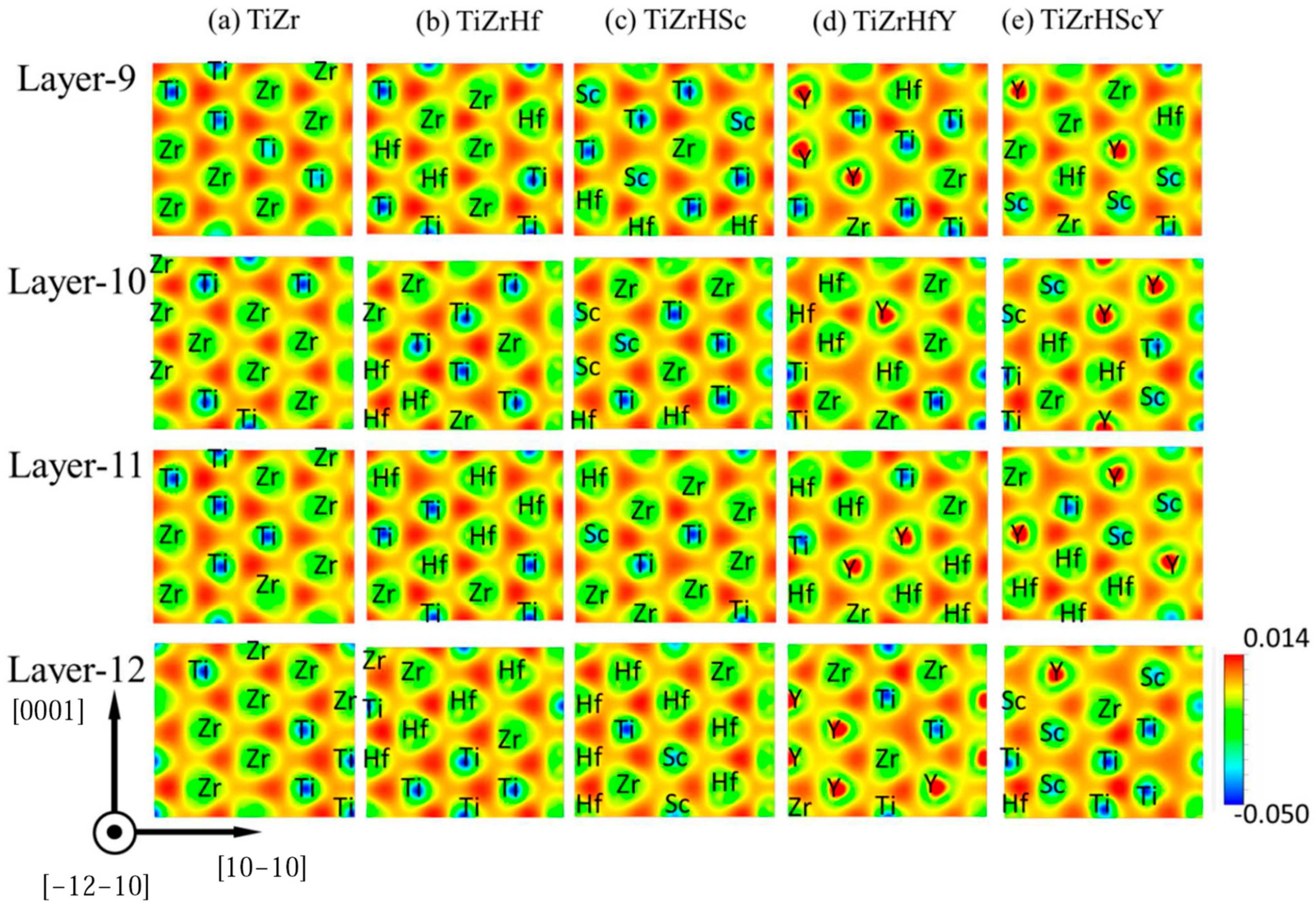
3.1. Lattice Parameters and Lattice Distortion of HCP CSAs

Based on the first-principles calculations, the obtained lattice parameters of CSAs are summarized in Table 1 in comparison with those measured in experiments. The calculated lattice parameters of TiZrHf and TiZrHfSc agree well with experimental results, and the errors are less than 1%, demonstrating that the supercells can be used for the first-principles investigations on the deformation mechanisms and mechanical properties of CSAs. Moreover, the volume of a CSA supercell increases when more alloying elements are introduced, as shown in Figure 3a. In the TiZr-based HCP CSAs, the addition of Y leads to a more significant enlargement in the volume of the CSA than that caused by adding Sc or Hf, while the effect of Sc addition on the volume enlargement is not significant as compared with that of Hf or Y additions. The calculated free energy indicates that the HCP structure of TiZrHf is more stable than that of the other TiZr-based HCP CSAs, while the free energy of TiZrHfScY is the highest among the five CSAs studied.
The chemical disorder in CSAs inevitably results in the lattice distortion of the system at equilibrium, which is considered to be responsible for the high mechanical strength in disordered alloys and is calculated with the following equation [40]:
Δ d = 1 N i N x i x i 2 + y i y i 2 + z i z i 2   ,  
where (xi, yi, zi) are the coordinates of atom i at the ideal lattice site, (x′i, y′i, z′i) are the coordinates of atom i at the distorted lattice site, and N is the number of atoms. The lattice distortion was found to be closely related to the atomic size mismatch δ described as follows [9]:
δ = 100 i = 1 n c i 1 r i r ¯ 2   ,  
where r ¯ = i = 1 n c i r i and ci and ri are atomic percentage and atomic radius of an individual constituent alloy element in the system, respectively. The calculated lattice distortion and atomic size mismatch of CSAs are shown in Figure 3b, and the lattice parameters, atomic radius, melting point, and valance electrons of the constituent alloy elements in the CSAs are listed in Table 2. It is found that the lattice distortion and atomic size mismatch are closely related to each other, i.e., the lattice distortion increases with increasing atomic size mismatch. In particular, among the CSAs studied, the lowest lattice distortion and atomic size mismatch are determined to be for TiZrHfSc and TiZrHf, respectively. Meanwhile, the addition of Hf in TiZr alloy tends to reduce the lattice distortion and atomic size mismatch. When Sc or Y is introduced to TiZrHf, Sc tends to reduce the lattice distortion, but it enhances the atomic size mismatch. On the contrary, Y addition is found to enhance both parameters. However, when Sc and Y are added to the TiZrHf CSA, significant increases in lattice distortion and atomic size mismatch can be observed. It is thus concluded that because of its low lattice distortion, TiZrHfSc can possess a perfect HCP structure in comparison with other CSAs.

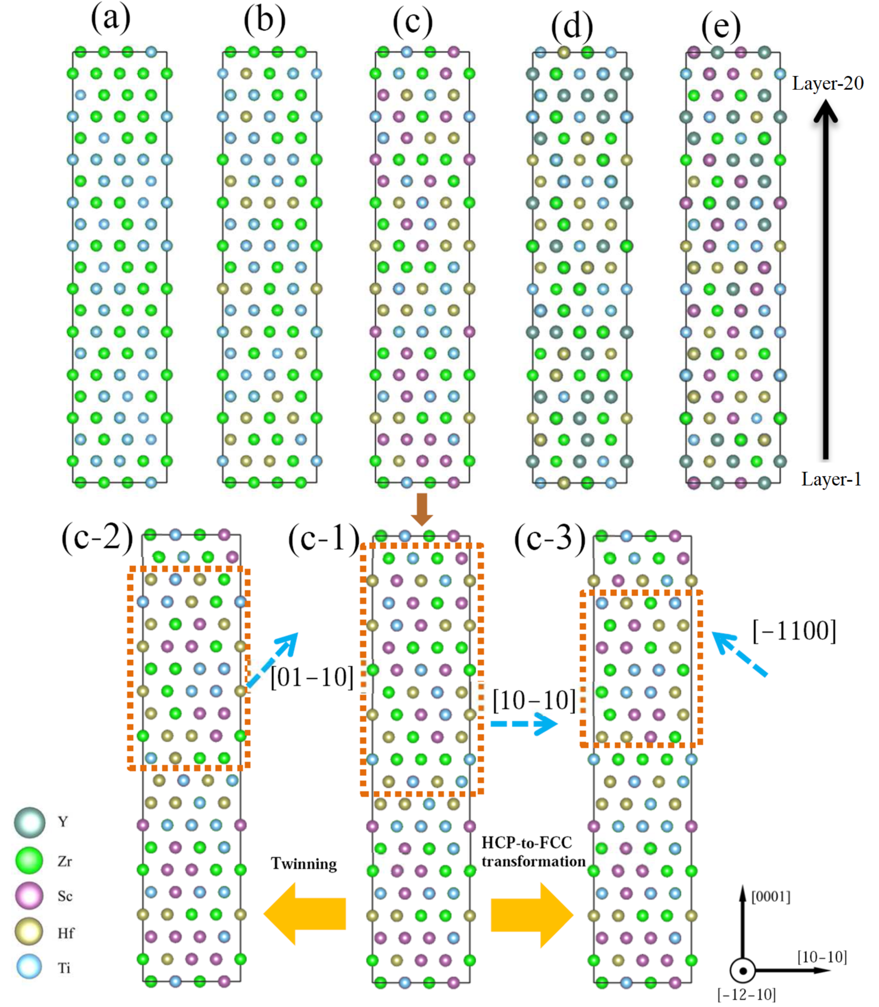
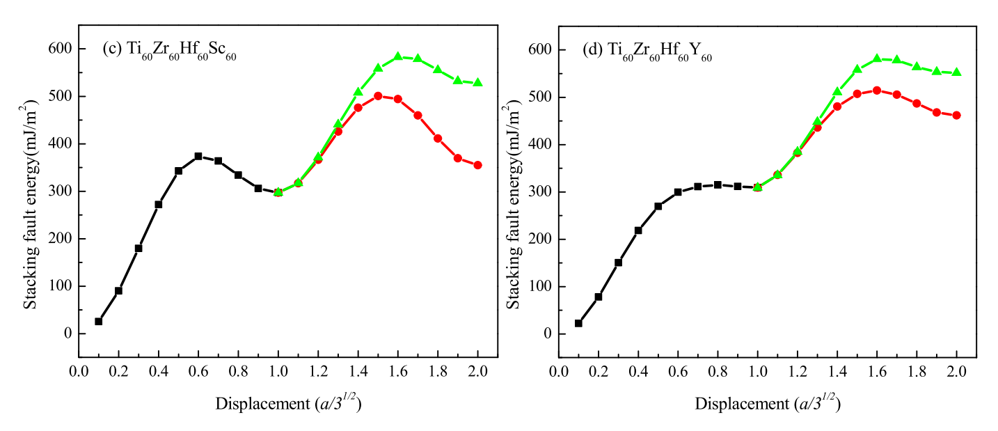
3.2. Deformation Mechanisms in HCP CSAs

The stacking-fault energies γ can be determined as γ(g) = [E(g) − E0]/2A, where g is the displacement along a specific direction in the generation of stacking faults, E(g) and E0 represent the total energy of the supercell with and without the stacking faults, respectively, and A is the stacking-fault area. Figure 4 presents the calculated GPFE curves of the CSAs studied. As marked in Figure 4e, the stacking-fault energy (γSF), twinning-fault energy (γTF), and FCC-fault energy (γFCCF) are the local minima at the ends of the three GPFE curves, respectively. At the same time, the three peak values of the curves are defined as unstable stacking-fault energy (γUSF), unstable twinning-fault energy (γUTF), and unstable FCC-fault energy (γUFCCF), respectively. Table 3 lists those values with the energy barriers for the formation of twin faults (∆UT = γUTFγSF) and FCC faults (∆UF = γUFCCFγSF) with the pre-existing stacking faults, which can be used to clarify the competition between deformation twinning and HCP-to-FCC transformation in the HCP systems.
It is found that the addition of Hf in TiZr CSA tends to enhance γUSF and γSF; the additions of Sc and Y in TiZrHf CSA tend to reduce γSF, while Sc or Y addition can enhance or reduce γUSF, respectively. However, both γUSF and γSF for TiZrHfSc or TiZrHfY are smaller than those for TiZrHfScY. Comparing γUSF and γSF for TiZrHfSc, TiZrHfY, and TiZrHfScY, which are usually defined as HEAs, it is found that γSF decreases with the increasing number of constituent alloy elements. Since γUSF is considered to be the energy barrier that a partial dislocation must overcome to move in an HCP alloy, the reduced γUSF can facilitate the dislocation-mediated slips. It is thus concluded that adding Hf into TiZr CSA or adding Sc into TiZrHf CSA tends to weaken the dislocation-mediated slips. On the contrary, the addition of Y in TiZrHf CSA can promote dislocation-mediated slips, and adding Y and Sc in TiZrHf CSA can significantly improve the activities of dislocation-mediated slips.
For the CSAs studied, the energy barrier for the formation of FCC faults is larger than that of twin faults, implying that the deformation mechanisms of those HCP CSAs tend to be deformation twinning instead of HCP-to-FCC transformation at 0 K. For the TiZr CSA, the difference in energy barriers for the formation of twin faults and FCC faults is increased significantly with the addition of Hf, suggesting that the deformation twinning in the CSA is enhanced by adding Hf. Although the energy barriers for the formation of twin faults and FCC faults are increased by adding Sc or Y into TiZrHf, the difference in these energy barriers seems unchanged for TiZrHfSc HEA, while it is reduced for TiZrHfSc HEA. It is thus suggested that the deformation twinning and HCP-to-FCC transformation are hindered by the addition of Sc or Y in TiZrHf CSA, while in the resulting HEAs, the HCP-to-FCC transformation in TiZrHfY is easier to occur than that in TiZrHfSc. In particular, the transformation is more difficult to occur in TiZrHfScY HEA than in other CSAs studied since deformation twinning is more energetically favorable as compared to the HCP-to-FCC transformation in TiZrHfScY HEAs.
Based on the calculated GPFE curves, the relationship between the dislocation activities and the ductility εp of CSAs can be explained in comparison with experimental results listed in Table 4. When Y is added to TiZrHf, the difference in the energy barriers for the formation of twin faults and FCC faults is decreased from 86 mJ/m2 to 66 mJ/m2. Hence, the dislocation activities in TiZrHfY can be more intense than those in TiZrHf, resulting in an increase in the ductility of TiZrHfY compared with that of TiZrHf. When Y is added to TiZrHfSc, the difference in the energy barriers for the formation of twin faults and FCC faults is increased from 83 mJ/m2 to 142 mJ/m2, leading to an obvious decrease in ductility of TiZrHfScY compared with that of TiZrHfSc.
Generally, the mechanical properties of alloys can be related to the characteristics of metallic bonding in the alloys, which are determined by the electronic structures. Herein, the redistribution of charge density Δρ(r) = ρ(r) − Σρ0(X, r) of CSAs is characterized using first-principles calculations, where ρ(r) is the charge density of CSA at position r; ρ0(X, r) is the charge density of atoms of a constituent alloy element X, which is isolated from those of other constituent alloy elements. The term Δρ(r) describes the charge redistribution induced by the alloying elements in the CSA and directly reflects the bonding nature between the constituent alloy elements. In order to have a better understanding of the redistribution of electrons in the CSAs under plastic deformation, those at the atom layers close to the (0001) glide plane, which are related to the formation of twins or faults, are shown in Figure 5.
Based on Figure 5, the reasons why the addition of Y in CSAs can reduce the yield strength σy of the resulting TiZrHfY and TiZrHfScY HEAs (as listed in Table 4) can be explained as follows: As shown in Figure 5b,d and Figure 5c,e, respectively, the charge-density redistributions in the TiZrHfY and TiZrHfScY HEAs indicate that the redistributions of electrons around Y atoms exhibit strong localization since large values of Δρ(r) can be associated with the metallic bonding between Y and other atoms. As a result, the addition of Y to the TiZrHf or TiZrHfSc CSAs thus disturbs the evenly distributed metallic bonding significantly, as shown in Figure 5d,e, respectively. Consequently, the strength of bonding or interaction between adjacent (0001) slip planes can be significantly weakened by the addition of Y in the resulting HEAs, leading to significant reductions in the yield strengths of TiZrHfY and TiZrHfScY HEAs in comparison with those of TiZrHf and TiZrHfSc, respectively.

3.3. Mesoscopic Studies on Dislocation Plasticity of CSAs

In order to have a better understanding of the mechanical properties of CSAs, the kinetics of an edge dislocation with the Burgers vector b = a/3[−12–10] is studied by solving Equations (1) and (2), where the positions of the dislocation line uij(t) = (ui,j(t), vi,j(t)) can be determined at time t at the discrete lattice sites labeled with 1 ≤ j ≤ 600 and 1 ≤ j ≤ 1000.
The parameters of Equations (1) and (2) for the TiZr, TiZrHf, TiZrHfSc, TiZrHfY, and TiZrHfScY CSA systems are determined by the aforementioned first-principles calculations at T = 0 K. The energy barrier for the activation of dislocation kinks, V0, is approximated as the unstable stacking-fault energy γUSF. The shear modulus G of CSA is determined by calculating the elastic deformation with Hooke’s law for the CSA supercell shown in Figure 1, which is listed in Table 4. Since the first-principles calculations on the parameters are performed on the CSAs at T = 0 K, the calculated values of V0 and G may be over-estimated for Equations (1) and (2), which is employed to predict the mechanical properties of CSAs at a finite temperature. However, the effects of temperature on the predicted mechanical properties are not significant, resulting from the consistency between the lattice parameters predicted at T = 0 K and those experimental values measured at a finite temperature, as listed in Table 1.
The Runge–Kutta method is used to solve Equations (1) and (2), and periodic boundary conditions are applied at the x- and y-directions. The activation of dislocation kinks and the motion of dislocation are simulated by acting forces of f = (−F/2, 31/2F/2) on the dislocation line, which measure the applied shear stress on the slip plane. When the force F is increased from 0 with an increment of 0.01 N/m, kinks are generated while parts of the dislocation line may remain static or the kinks are at rest. It is not until F reaches a critical value Fcr that the whole dislocation line moves along f with a distance greater than bp = 31/2a/3, or the kinks have moved across the slip plane. Therefore, by solving Equation (1), Fcr can be determined for the TiZr, TiZrHf, TiZrHfSc, TiZrHfY, and TiZrHfScY CSA systems, which can measure the shear strengths τy of the CSAs, as listed in Table 4.
The available mechanical properties of the CSAs obtained from experimental measurements [16] are listed in Table 4, where the dislocation shear strength τdis can be calculated from the experimental value of yield strength σy using the relation τdis = σy/3 in polycrystalline materials. Remarkably, the shear strength τy of the CSAs determined by the kink-dislocation model is consistent with that (τdis) obtained from experiments, as listed in Table 4. The results suggest that the mesoscopic kink-dislocation model, with its parameter determined using the first-principles calculation, is effective in quantitatively predicting the mechanical properties of CSAs. Thus, the multiscale simulation approach combining the first-principles calculation and kink-dislocation model can be very robust in the simulation of the dislocation plasticity of CSAs.

4. Conclusions

In summary, a multiscale simulation approach combining first-principles calculations and the Frenkel–Kontonova kink-dislocation model is employed to investigate the dislocation plasticity of TiZr-based HCP CSAs. For the first time, the GPFE curves obtained using first-principles calculations are utilized to determine the energy barriers for the formations of stacking faults, twin faults, and FCC faults in the CSAs. The calculated GPFE curves indicate that, for HEAs formed by adding HCP elements in TiZrHf CSA, the dislocation-mediated slip is promoted or reduced by the addition of Y or Sc, respectively, while it is significantly enhanced by simultaneously adding Y and Sc. Furthermore, the formulism of a mesoscopic kink-dislocation model is established to quantitatively predict the mechanical properties of TiZr-based HCP CSAs, which are consistent with experimental results. The results demonstrate that the multiscale simulation approach developed in this work is robust in investigating the dislocation plasticity of CSAs and can facilitate the development of new HCP HEAs with improved mechanical properties.

Author Contributions

Conceptualization, G.Z.; methodology, Y.L. and G.Z.; software, Y.L. and G.Z.; validation, Y.L. and G.Z.; formal analysis, Y.L. and G.Z.; investigation, Y.L. and G.Z.; resources, Y.L. and G.Z.; data curation, Y.L. and G.Z.; writing—original draft preparation, Y.L.; writing—review and editing, G.Z.; visualization, Y.L.; supervision, G.Z.; project administration, G.Z.; funding acquisition, Y.L. and G.Z. All authors have read and agreed to the published version of the manuscript.

Funding

This research was funded by the Research Grants Council of the Hong Kong Special Administrative Region, China grant number 15219018/18E And The APC is funded by Otto Poon Charitable Foundation.

Data Availability Statement

Data presented in this article are available at request from the corresponding author.

Acknowledgments

This work was supported by the Hong Kong Scholars Program (Grant No.: XJ2018011).

Conflicts of Interest

The authors declare no conflict of interest.

References

  1. Zhang, Y.; Stocks, G.M.; Jin, K.; Lu, C.; Bei, H.; Sales, B.C.; Wang, L.; Béland, L.K.; Stoller, R.E.; Samolyuk, G.D.; et al. Influence of chemical disorder on energy dissipation and defect evolution in concentrated solid solution alloys. Nat. Commun. 2015, 6, 8736. [Google Scholar] [CrossRef] [PubMed]
  2. Wu, Z.; Bei, H.; Pharr, G.M.; George, E.P. Temperature dependence of the mechanical properties of equiatomic solid solution alloys with face-centered cubic crystal structures. Acta Mater. 2014, 81, 428–441. [Google Scholar] [CrossRef]
  3. Gao, M.C.; Zhang, C.; Gao, P.; Zhang, F.; Ouyang, L.; Widom, M.; Hawk, J. Thermodynamics of concentrated solid solution alloys. Curr. Opin. Solid State Mater. Sci. 2017, 21, 238–251. [Google Scholar] [CrossRef]
  4. Gao, L.; Chen, R.; Han, E. Solid solution strengthening behaviors in binary Mg–Y single phase alloys. J. Alloy Compd. 2009, 472, 234–240. [Google Scholar] [CrossRef]
  5. Huang, Y.-S.; Chen, L.; Lui, H.-W.; Cai, M.-H.; Yeh, J.-W. Microstructure, hardness, resistivity and thermal stability of sputtered oxide films of AlCoCrCu0.5NiFe high-entropy alloy. Mater. Sci. Eng. A 2007, 457, 77–83. [Google Scholar] [CrossRef]
  6. Senkov, O.N.; Scott, J.M.; Senkova, S.V.; Miracle, D.B.; Woodward, C.F. Microstructure and room temperature properties of a high-entropy TaNbHfZrTi alloy. J. Alloys Compd. 2011, 509, 6043–6048. [Google Scholar] [CrossRef]
  7. Manzoni, A.; Daoud, H.; Mondal, S.; van Smaalen, S.; Völkl, R.; Glatzel, U.; Wanderka, N. Investigation of phases in Al23Co15Cr23Cu8Fe15Ni16 and Al8Co17Cr17Cu8Fe17Ni33 high entropy alloys and comparison with equilibrium phases predicted by Thermo-Calc. J. Alloy Compd. 2013, 552, 430–436. [Google Scholar] [CrossRef]
  8. Murty, B.S.; Yeh, J.-W.; Ranganathan, S.; Bhattacharjee, P. High-Entropy Alloys; Elsevier: Amsterdam, The Netherlands, 2019. [Google Scholar]
  9. Zhang, Y.; Zuo, T.T.; Tang, Z.; Gao, M.C.; Dahmen, K.A.; Liaw, P.K.; Lu, Z.P. Microstructures and properties of high-entropy alloys. Prog. Mater. Sci. 2014, 61, 1–93. [Google Scholar] [CrossRef]
  10. Chen, Y.-L.; Tsai, C.-W.; Juan, C.-C.; Chuang, M.-H.; Yeh, J.-W.; Chin, T.-S.; Chen, S.-K. Amorphization of equimolar alloys with HCP elements during mechanical alloying. J. Alloy Compd. 2010, 506, 210–215. [Google Scholar] [CrossRef]
  11. Youssef, K.M.; Zaddach, A.J.; Niu, C.; Irving, D.L.; Koch, C.C. A Novel Low-Density, High-Hardness, High-entropy Alloy with Close-packed Single-phase Nanocrystalline Structures. Mater. Res. Lett. 2014, 3, 95–99. [Google Scholar] [CrossRef]
  12. Gao, M.C.; Zhang, B.; Guo, S.; Qiao, J.; Hawk, J. High-entropy alloys in hexagonal close-packed structure. Metall. Mater. Trans. A 2016, 47, 3322–3332. [Google Scholar] [CrossRef]
  13. Gao, M.C.; Alman, D.E. Searching for Next Single-Phase High-Entropy Alloy Compositions. Entropy 2013, 15, 4504–4519. [Google Scholar] [CrossRef]
  14. Takeuchi, A.; Amiya, K.; Wada, T.; Yubuta, K.; Zhang, W. High-Entropy Alloys with a Hexagonal Close-Packed Structure Designed by Equi-Atomic Alloy Strategy and Binary Phase Diagrams. JOM 2014, 66, 1984–1992. [Google Scholar] [CrossRef]
  15. Feuerbacher, M.; Heidelmann, M.; Thomas, C. Hexagonal high-entropy alloys. Mater. Res. Lett. 2015, 3, 1–6. [Google Scholar] [CrossRef]
  16. Huang, T.; Jiang, H.; Lu, Y.; Wang, T.; Li, T. Effect of Sc and Y addition on the microstructure and properties of HCP-structured high-entropy alloys. Appl. Phys. A 2019, 125, 180. [Google Scholar] [CrossRef]
  17. Rogal, Ł.; Czerwinski, F.; Jochym, P.; Litynska-Dobrzynska, L. Microstructure and mechanical properties of the novel Hf25Sc25Ti25Zr25 equiatomic alloy with hexagonal solid solutions. Mater. Des. 2016, 92, 8–17. [Google Scholar] [CrossRef]
  18. Zhang, F.; Zhao, S.; Jin, K.; Bei, H.; Popov, D.; Park, C.; Neuefeind, J.C.; Weber, W.J.; Zhang, Y. Pressure-induced fcc to hcp phase transition in Ni-based high entropy solid solution alloys. Appl. Phys. Lett. 2017, 110, 011902. [Google Scholar] [CrossRef]
  19. Niu, C.; LaRosa, C.R.; Miao, J.; Mills, M.J.; Ghazisaeidi, M. Magnetically-driven phase transformation strengthening in high entropy alloys. Nat. Commun. 2018, 9, 1–9. [Google Scholar] [CrossRef] [PubMed]
  20. Basu, S.; Li, Z.; Pradeep, K.G.; Raabe, D. Strain Rate Sensitivity of a TRIP-Assisted Dual-Phase High-Entropy Alloy. Front. Mater. 2018, 5, 30. [Google Scholar] [CrossRef]
  21. Siegel, D.J. Generalized stacking fault energies, ductilities, and twinnabilities of Ni and selected Ni alloys. Appl. Phys. Lett. 2005, 87, 121901. [Google Scholar] [CrossRef]
  22. Achmad, T.L.; Fu, W.; Chen, H.; Zhang, C.; Yang, Z.-G. Effects of alloying elements concentrations and temperatures on the stacking fault energies of Co-based alloys by computational thermodynamic approach and first-principles calculations. J. Alloy Compd. 2017, 694, 1265–1279. [Google Scholar] [CrossRef]
  23. Achmad, T.L.; Fu, W.; Chen, H.; Zhang, C.; Yang, Z.-G. First-principles calculations of generalized-stacking-fault-energy of Co-based alloys. Comput. Mater. Sci. 2016, 121, 86–96. [Google Scholar] [CrossRef]
  24. MacLaren, J.M.; Gonis, A.; Schadler, G. First-principles calculation of stacking-fault energies in substitutionally disordered alloys. Phys. Rev. B 1992, 45, 14392–14395. [Google Scholar] [CrossRef]
  25. Zhao, S.; Stocks, G.M.; Zhang, Y. Stacking fault energies of face-centered cubic concentrated solid solution alloys. Acta Mater. 2017, 134, 334–345. [Google Scholar] [CrossRef]
  26. Zhang, Y.; Zhuang, Y.; Hu, A.; Kai, J.; Liu, C. The origin of negative stacking fault energies and nano-twin formation in face-centered cubic high entropy alloys. Scr. Mater. 2016, 130, 96–99. [Google Scholar] [CrossRef]
  27. Zunger, A.; Wei, S.H.; Ferreira, L.; Bernard, J. Special quasirandom structures. Phys. Rev. Lett. 1990, 65, 353–356. [Google Scholar] [CrossRef] [PubMed]
  28. van de Walle, A.; Tiwary, P.; de Jong, M.; Olmsted, D.; Asta, M.; Dick, A.; Shin, D.; Wang, Y.; Chen, L.-Q.; Liu, Z.-K. Efficient stochastic generation of special quasirandom structures. Calphad 2013, 42, 13–18. [Google Scholar] [CrossRef]
  29. Hafner, J. Ab-initio simulations of materials using VASP: Density-functional theory and beyond. J. Comput. Chem. 2008, 29, 2044–2078. [Google Scholar] [CrossRef] [PubMed]
  30. Kresse, G.; Furthmüller, J. Efficient iterative schemes for ab initio total-energy calculations using a plane-wave basis set. Phys. Rev. B 1996, 54, 11169–11186. [Google Scholar] [CrossRef] [PubMed]
  31. Kresse, G.; Joubert, D. From ultrasoft pseudopotentials to the projector augmented-wave method. Phys. Rev. B 1999, 59, 1758–1775. [Google Scholar] [CrossRef]
  32. Blöchl, P. Projector augmented-wave method. Phys. Rev. B 1994, 50, 17953. [Google Scholar] [CrossRef] [PubMed]
  33. Perdew, J.P.; Burke, K.; Ernzerhof, M. Generalized gradient approximation made simple. Phys. Rev. Lett. 1996, 77, 3865. [Google Scholar] [CrossRef] [PubMed]
  34. Perdew, J.P.; Chevary, J.A.; Vosko, S.H.; Jackson, K.A.; Pederson, M.R.; Singh, D.J.; Fiolhais, C. Atoms, molecules, solids, and surfaces: Applications of the generalized gradient approximation for exchange and correlation. Phys. Rev. B 1992, 46, 6671–6687. [Google Scholar] [CrossRef]
  35. Wisesa, P.; McGill, K.A.; Mueller, T. Efficient generation of generalized Monkhorst-Pack grids through the use of informatics. Phys. Rev. B 2016, 93, 155109. [Google Scholar] [CrossRef]
  36. Zheng, G. Molecular dynamics and first-principles studies on the deformation mechanisms of nanostructured cobalt. J. Alloy Compd. 2010, 504, S467–S471. [Google Scholar] [CrossRef]
  37. Frenkel, J.; Kontorova, T. On the theory of plastic deformation and twinning. Izv. Akad. Nauk. SSSR Seriya Fiz. 1939, 1, 137–149. [Google Scholar]
  38. Lomdahl, P.S.; Srolovitz, D.J. Dislocation Generation in the Two-Dimensional Frenkel-Kontorova Model at High Stresses. Phys. Rev. Lett. 1986, 57, 2702–2705. [Google Scholar] [CrossRef]
  39. Srolovitz, D.; Lomdahl, P. Dislocation dynamics in the 2-D Frenkel-Kontorova model. Phys. D Nonlinear Phenom. 1986, 23, 402–412. [Google Scholar] [CrossRef]
  40. Song, H.; Tian, F.; Hu, Q.-M.; Vitos, L.; Wang, Y.; Shen, J.; Chen, N. Local lattice distortion in high-entropy alloys. Phys. Rev. Mater. 2017, 1, 023404. [Google Scholar] [CrossRef]
  41. Spedding, F.H.; Daane, A.H.; Herrmann, K.W. The crystal structures and lattice parameters of high-purity scandium, yttrium and the rare earth metals. Acta Crystallogr. 1956, 9, 559–563. [Google Scholar] [CrossRef]
  42. Raffy, C.; Furthmüller, J.; Bechstedt, F. Properties of hexagonal polytypes of group-IV elements from first-principles calculations. Phys. Rev. B 2002, 66, 075201. [Google Scholar] [CrossRef]
Figure 1. Supercells of CSAs, (a) Ti120Zr120, (b) Ti80Zr80Hf80, (c) Ti60Zr60Hf60Sc60, (d) Ti60Zr60Hf60Y60, and (e) Ti48Zr48Hf48Sc48Y48. The generations of the stacking fault (c-1), faults related to deformation twinning (c-2), and HCP-to-FCC transformation (c-3) are demonstrated in the Ti60Zr60Hf60Sc60 supercell.
Metals 13 00351 g001
Figure 2. Hexagonal lattice sites (solid circles) on the (0001) slip plane of HCP CSAs. The lattice constant is a, and i and j are integers labeling the sites.
Metals 13 00351 g002
Figure 3. (a) Volume and free energy and (b) lattice distortion and atomic size mismatch of the TiZr-based CSAs.
Metals 13 00351 g003
Figure 4. (ae) The generalized planar fault energy curves of the TiZr-based CSAs, where a is the lattice parameter of the system studied.
Metals 13 00351 g004aMetals 13 00351 g004b
Figure 5. The redistribution of charge density (Δρ(r)) at some atom layers in the supercells of TiZr-based CSAs, (a) Ti120Zr120, (b) Ti80Zr80Hf80, (c) Ti60Zr60Hf60Sc60, (d) Ti60Zr60Hf60Y60 and (e) Ti48Zr48Hf48Sc48Y48. The color bar indicates the values of Δρ(r), in units of eV/bohr3. The atom layers 9–12 are close to the (0001) glide plane and are related to the formation of twins or faults shown in Figure 1.
Metals 13 00351 g005
Table 1. Lattice parameters a and c of CSAs obtained from the first-principles calculations (this work) and experimental studies [16,17].
Alloy SystemsThis WorkExperimental
acc/aac
TiZr3.0924.8751.577--
TiZrHf3.1384.9171.5673.162 a4.997 a
TiZrHfSc3.1664.9581.5663.184 b
3.198 a
5.013 b
5.046 a
TiZrHfY3.2515.0911.566--
TiZrHfScY3.2545.0861.563--
a Ref [16], b Ref [17].
Table 2. Lattice parameters and physical properties [41,42] of HCP constituent alloy elements of CSAs studied in this work.
ElementsLattice Constants (Å)c/aRadius (Å)Tm (℃)Valence Configurations
Tia = 2.9509
c = 4.6826
1.591.46216703p63d24s2
Zra = 3.232
c = 5.147
1.591.60318504s24p64d35s1
Hfa = 3.193
c = 5.052
1.571.57821505p65d26s2
Sca = 3.2899
c = 5.2529
1.591.64115393s23p63d24s1
Ya = 3.6451
c = 5.7305
1.571.80215264s24p64d15s2
Table 3. The calculated unstable stacking-fault energy (γUSF), stacking-fault energy (γSF), unstable twinning-fault energy (γUT), and unstable FCC-fault energy (γUFCC) and energy barriers for the formation of twin fault and FCC fault with pre-existing stacking faults for the TiZr-based CSAs.
Alloy SystemsγUSF (mJ/m2)γSF (mJ/m2)γUT (mJ/m2)γUFCC (mJ/m2)γUTγSF
(mJ/m2)
γUFCCγSF
(mJ/m2)
TiZr235216384396168180
TiZrHf357331513599182268
TiZrHfSc374297500583203286
TiZrHfY314309514580205271
TiZrHfScY271199379521180322
Table 4. Comparisons on the shear modulus G determined by first-principles calculation, shear strength τy predicted by kink-dislocation model, ductility εp and yield strength σy obtained from experimental measurements [16], and dislocation shear strength τdis = σy/3 for HCP CSAs.
TiZrTiZrHfTiZrHfScTiZrHfYTiZrHfScY
G (GPa)70.679.285.571.478.8
Shear strength
τy (MPa)
311.5 ± 1.4280.4 ± 1.0342.3 ± 1.5178.8 ± 1.0275.2 ± 1.2
Yield strength
σy (MPa)
-7731001554793
τdis (MPa)-257.6333.6184.6264.3
εp (%)-17.021.917.715.7
Disclaimer/Publisher’s Note: The statements, opinions and data contained in all publications are solely those of the individual author(s) and contributor(s) and not of MDPI and/or the editor(s). MDPI and/or the editor(s) disclaim responsibility for any injury to people or property resulting from any ideas, methods, instructions or products referred to in the content.

