
Effect of Roller Axial Position and Thickness on a Twisted Angle in the Twist Rolling of Aluminum Alloy 1050 Sheet Metal
Abstract
:1. Introduction
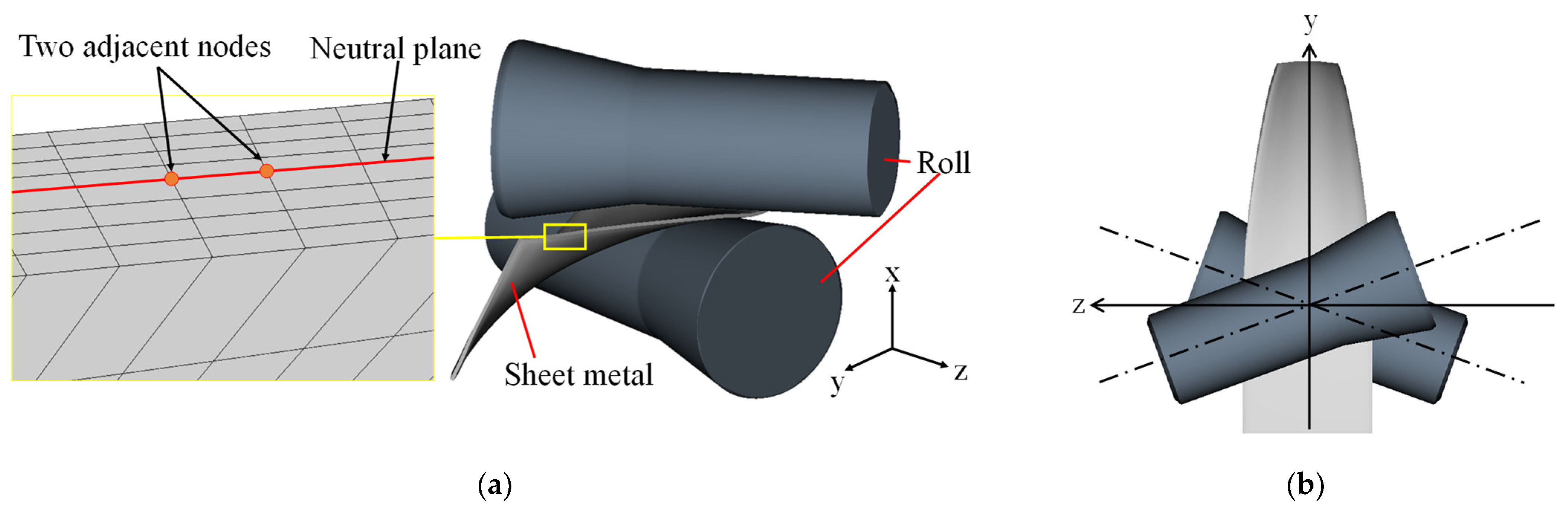
2. Proposal of Twist Rolling
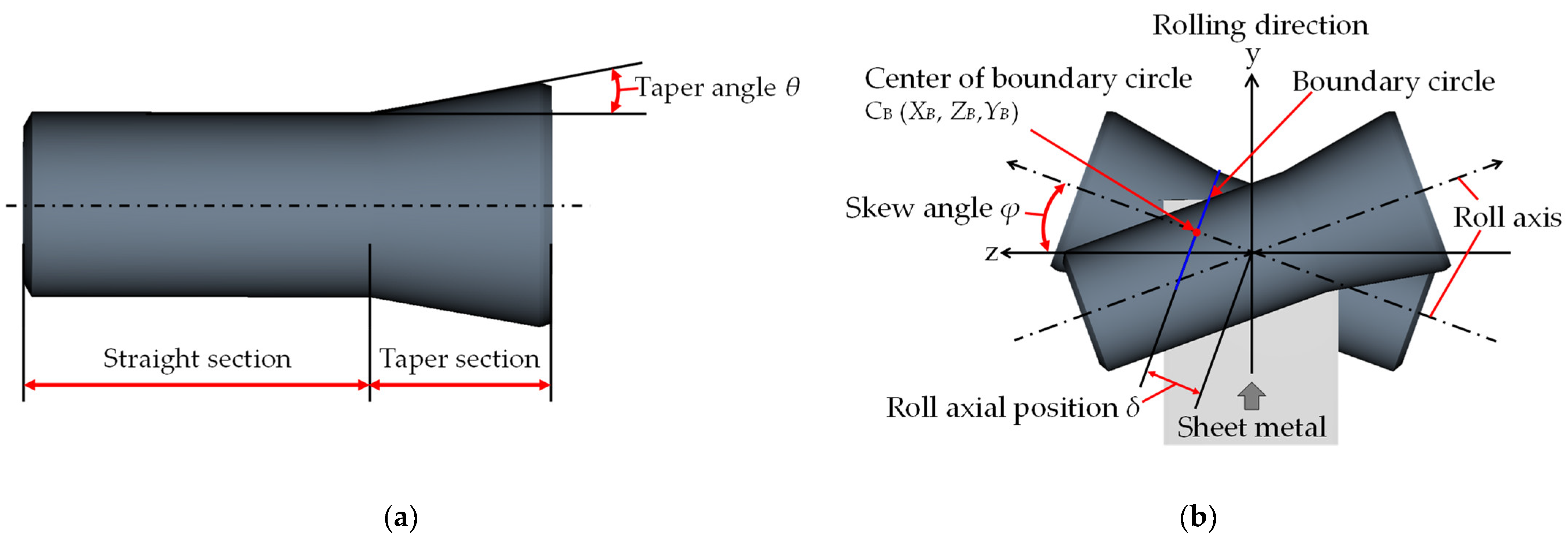
2.1. Structure and Principle
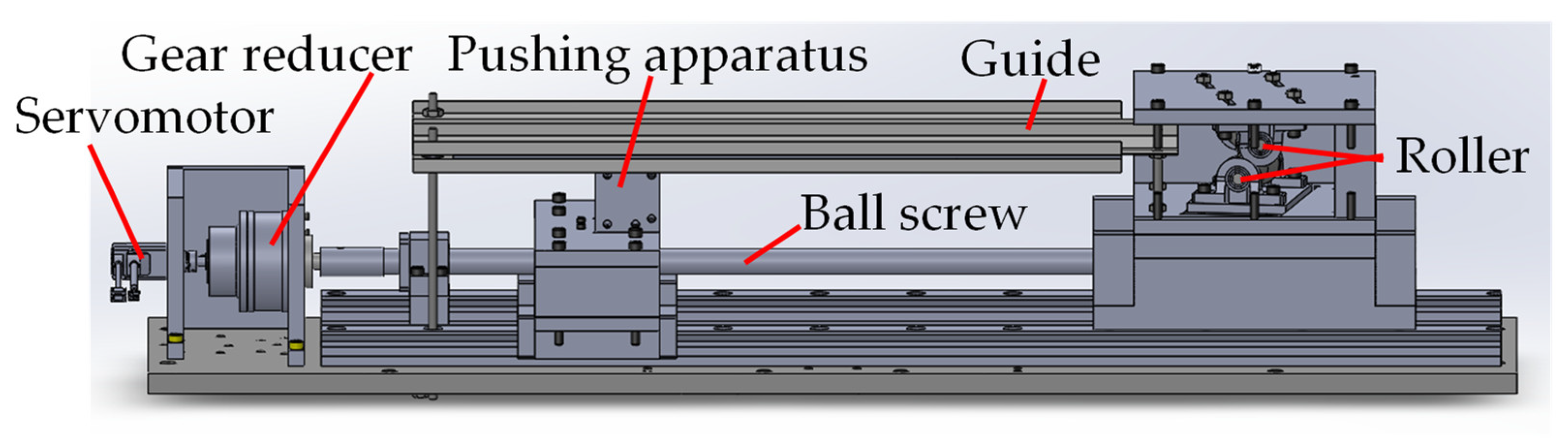
2.2. Schematic of Experimental Machine
3. Experimental and Analytical Methods
3.1. Sheet Metal and Properties
3.2. Experiment and Analysis Conditions
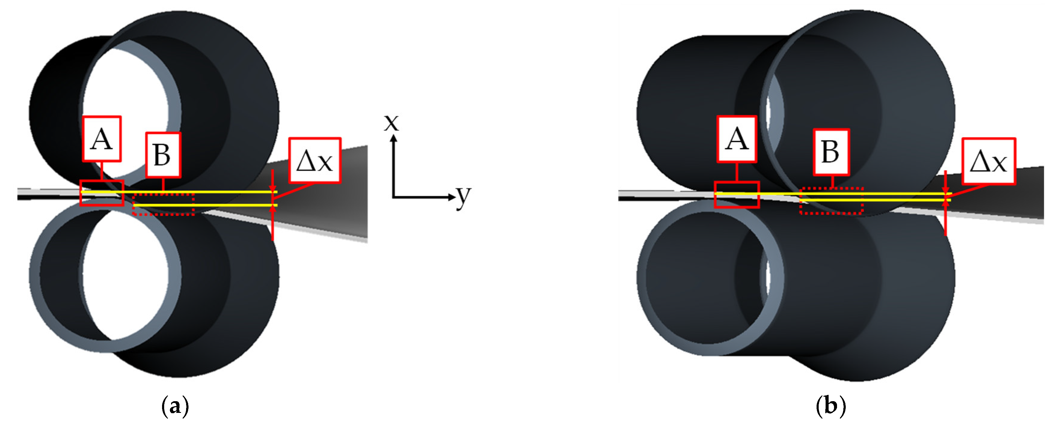
3.3. Evaluation Items and Method
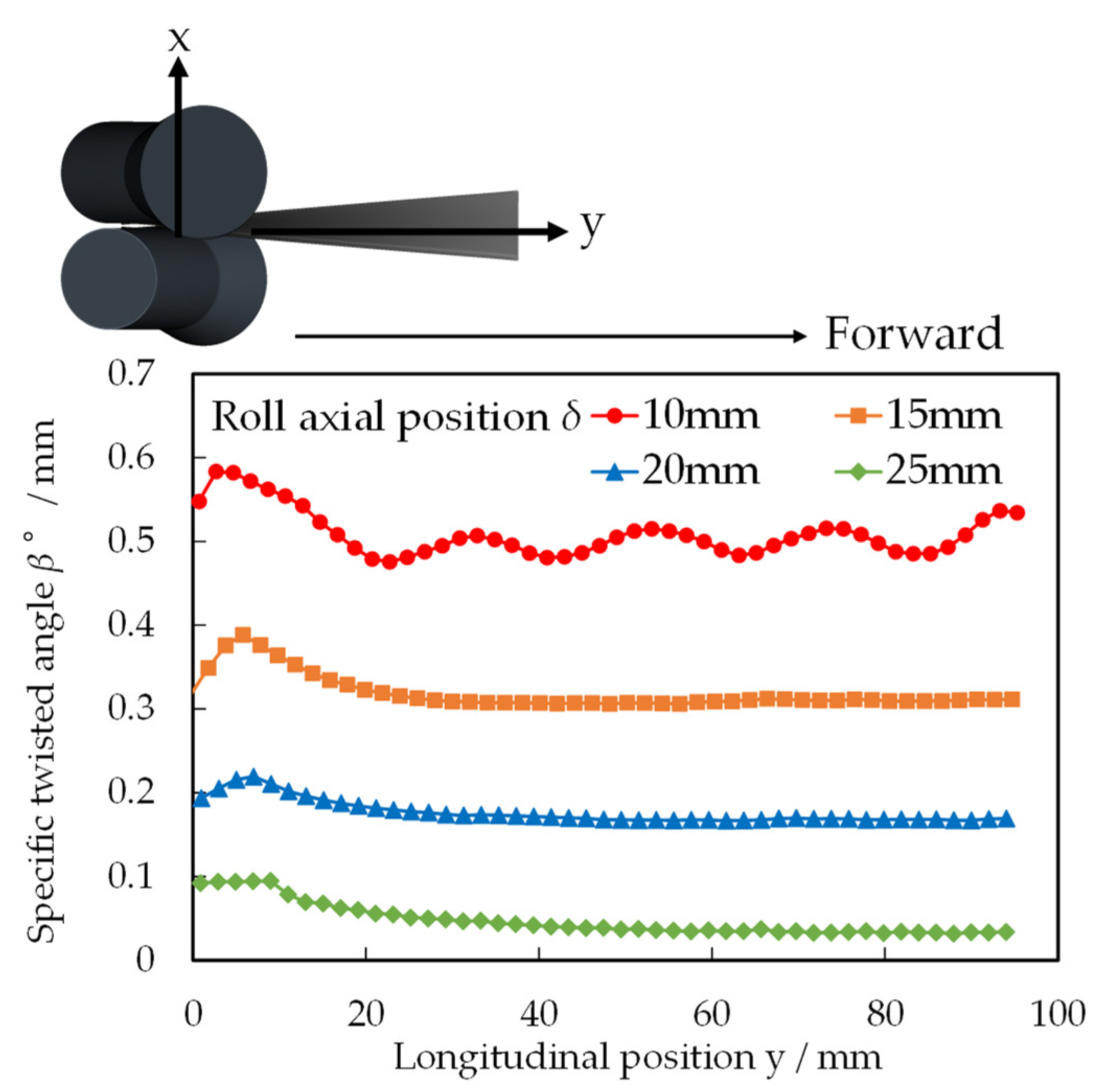
4. Effect of Roller Axial Position on Twisted Angle
4.1. Experiment and Analysis Results
4.2. Comparison and Discussion of Results
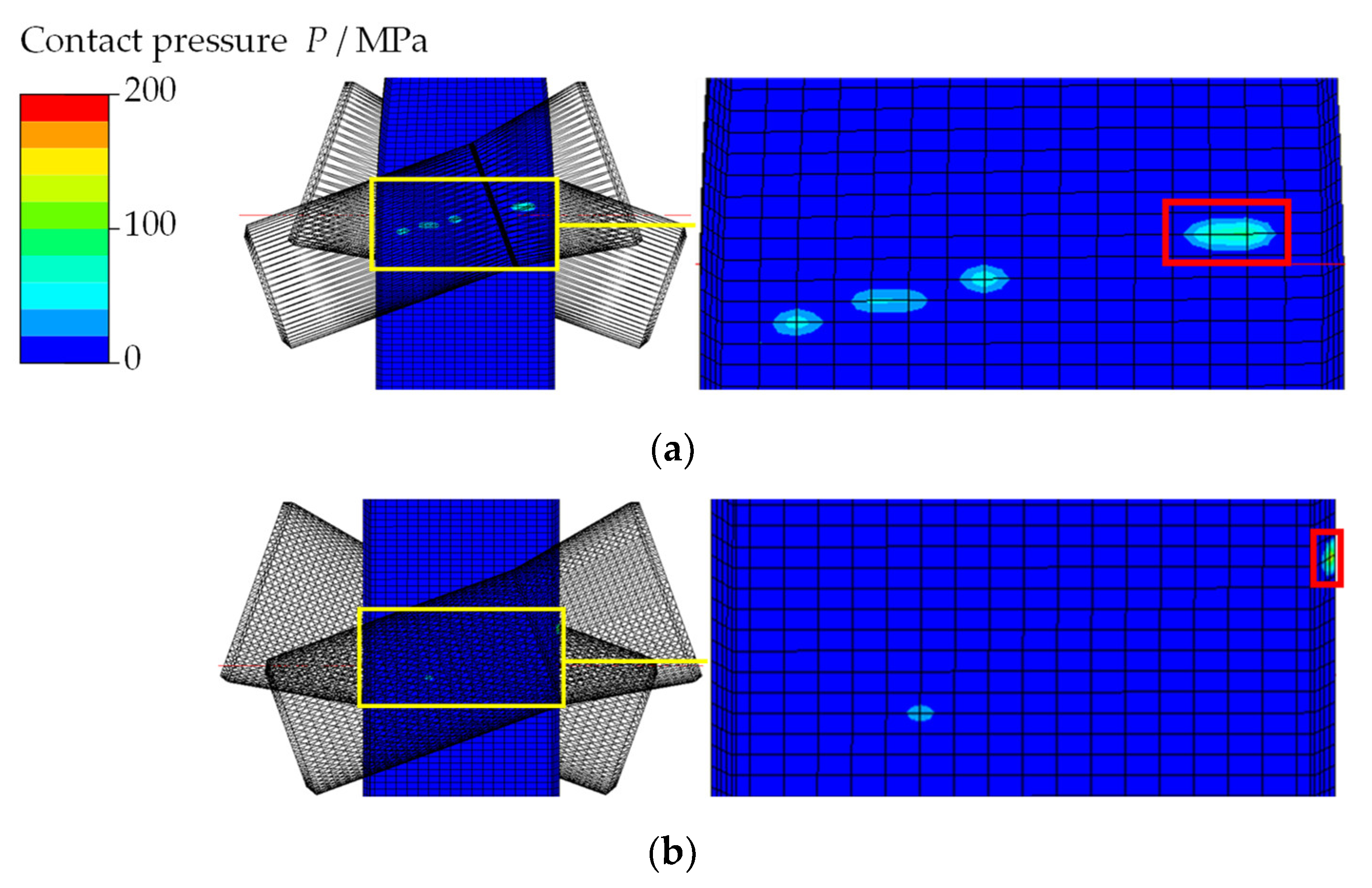
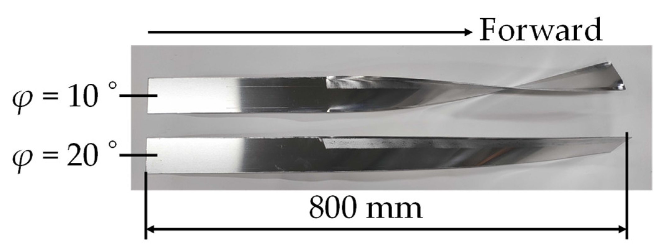
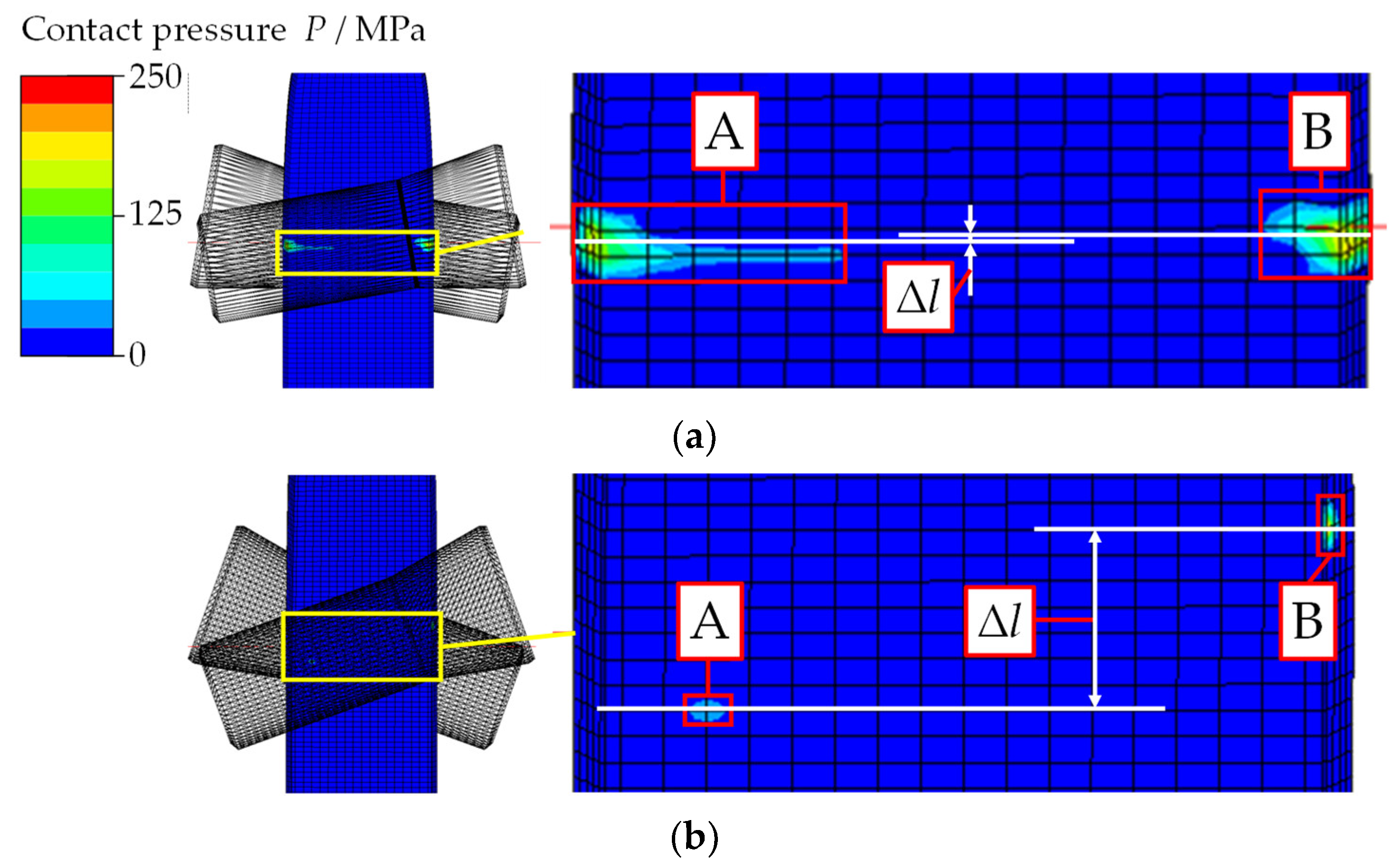
5. Effect of Roller Skew Angle on Twisted Angle
5.1. Experiment and Analysis Results
5.2. Comparison and Discussion of Results
6. Relationship between Sheet Metal Thickness and Twisted Angle
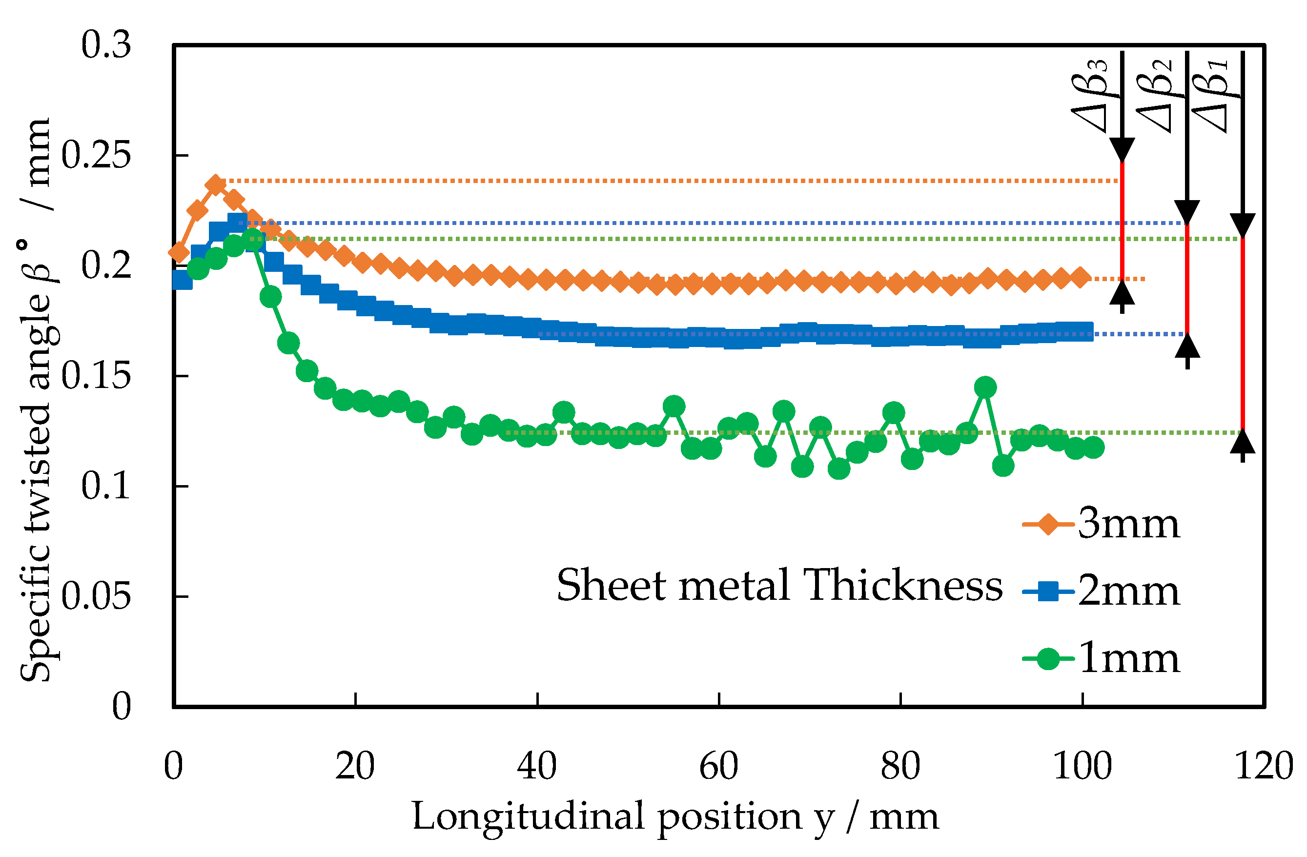
6.1. Experiment and Analysis Results
6.2. Comparison and Discussion of Results
7. Surface Roughness and Application to Products
7.1. Evaluation of Surface Roughness
7.2. Application to Products
8. Conclusions
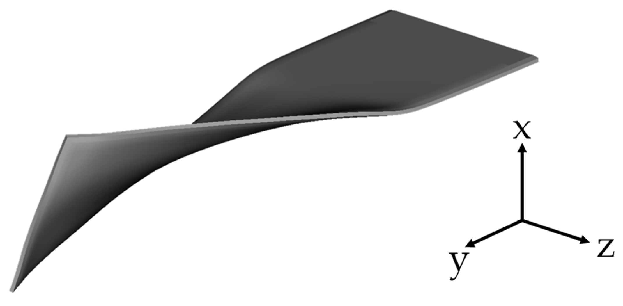
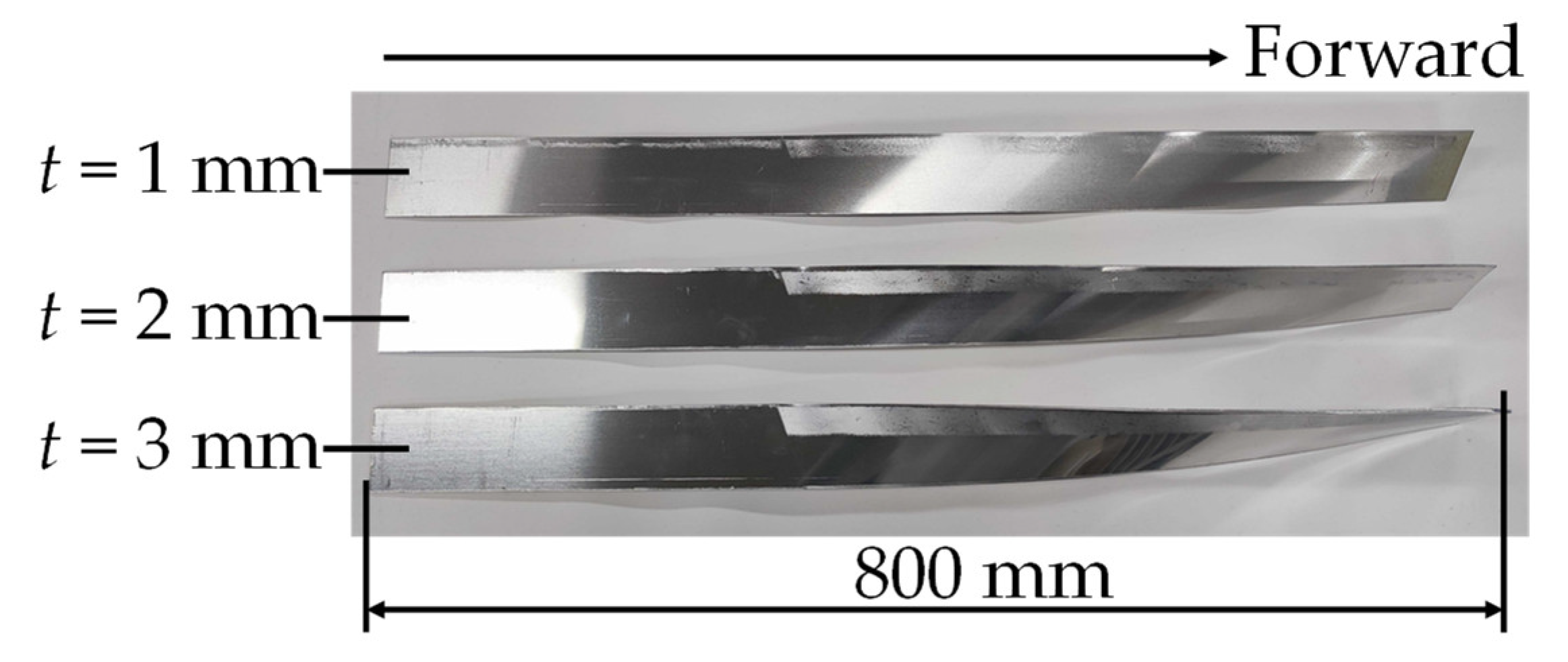
- A new processing method called “twist rolling” was developed to form continuously twisted shapes by rolling with taper rollers.
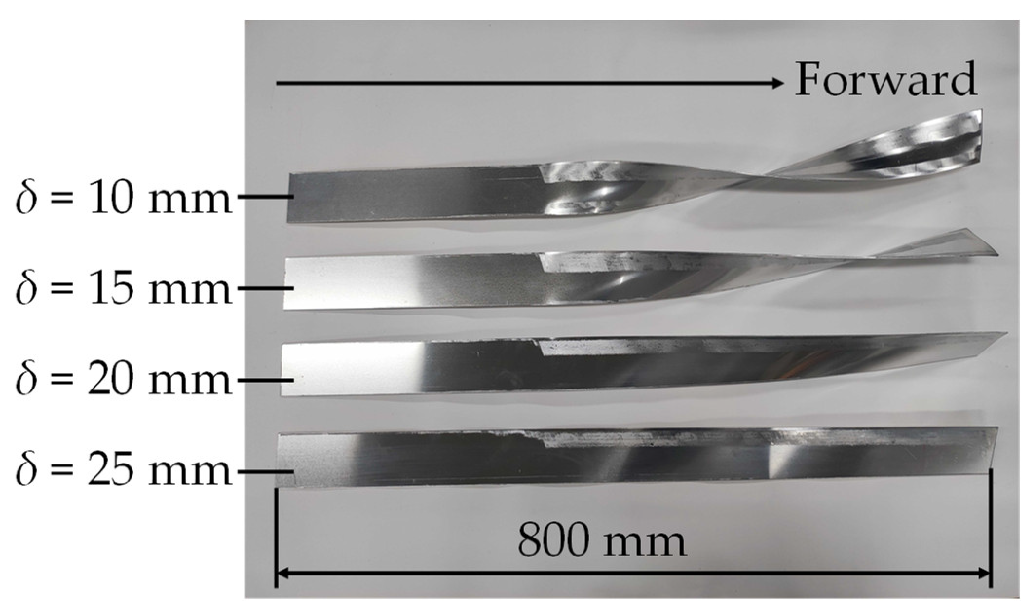
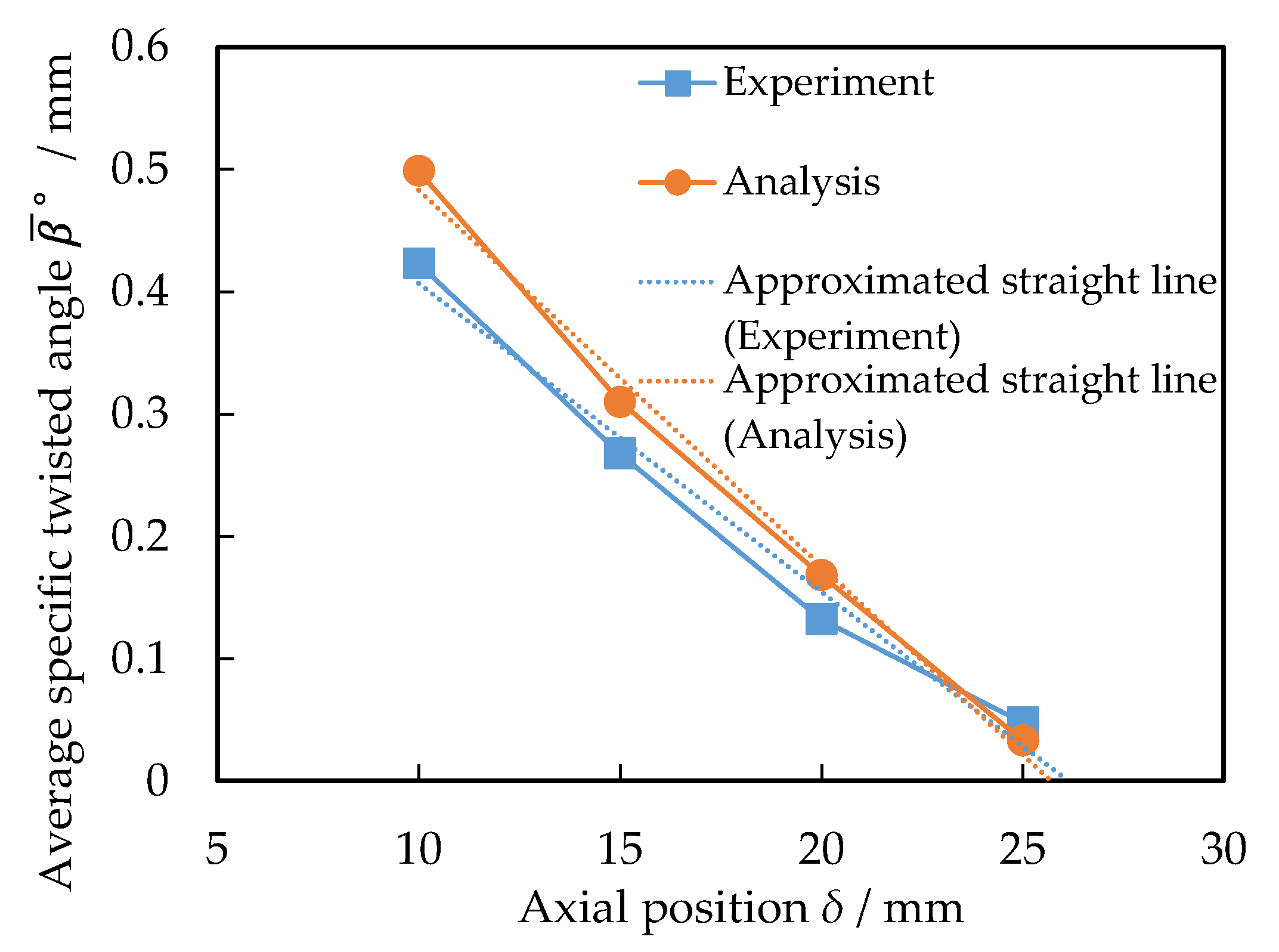
- The twisted angle increased as the roll axial position decreased, but if it was too small, large warpage appeared.
- The skew angle of 10° increased the twisted angle more than that of the 20° angle. This could be explained by the ratio of the distance in the height and rolling direction between the contact points at the taper and straight sections of the roller.
- The average twist angle decreased with the decrease in thickness as the springback was large for the thin sheet metals.
- The axial position of the rollers and the skew angle needed to be adjusted depending on the sheet metal thickness considering springback.
Author Contributions
Funding
Institutional Review Board Statement
Informed Consent Statement
Data Availability Statement
Conflicts of Interest
References
- Luo, S.; Wang, Q.; Zhang, P.; Li, J.; Liu, Q. Effect of friction conditions on phase transformation characteristics in hot forging process of Ti-6Al-4 V turbine blade. Mater. Res. Technol. 2020, 9, 2107–2115. [Google Scholar] [CrossRef]
- Koppensteiner, R.; Auer, M.; Fair, B. Gfm Radial Forging Machines for the Titanium Market. In Proceedings of the 13th World Conference on Titanium, San Diego, CA, USA, 16–20 August 2015. [Google Scholar]
- Makiyama, T.; Yagami, T.; Teramae, T.; Hirt, G. New Incremental Twist Forging; COMPLAS: Barcelona, Spain, 2015. [Google Scholar]
- Wolfgarten, M.; Rudolph, F.; Hirt, G. Analysis of process forces and geometrical correlations for open-die forging with superimposed manipulator displacements. Mater. Process. Technol. 2020, 276, 116408. [Google Scholar] [CrossRef]
- Qu, F.; Xu, J.; Jiang, Z. Finite Element Analysis of Forward Slip in Micro Flexible Rolling of Thin Aluminium Strips. Metals 2019, 9, 1062. [Google Scholar] [CrossRef]
- Ryabkov, N.; Jackel, F.; Putten, K.V.; Hirt, G. Production of blanks with thickness transitions in longitudinal and lateral direction through 3D-Strip Profile Rolling. Int. J. Mater. Form. 2008, 1, 391–394. [Google Scholar] [CrossRef]
- Li, H.W.; Ren, G.Y.; Li, Z.J.; Feng, L.; Yang, H. Forming mechanism and characteristics of a process for equal-thickness in-plane ring roll-bending of a metal strip by twin conical rolls. Mater. Process. Technol. 2015, 227, 288–307. [Google Scholar] [CrossRef]
- Rumualdo, S.; Sixtos, A.A.; Ismael, C.; Alejandro, P.; Sandra, M.S. Effect of Crown Shape of Rolls on the Distribution of Stress and Elastic Deformation for Rolling Processes. Metals 2019, 9, 1222. [Google Scholar] [CrossRef]
- Kuboki, T.; Kajikawa, S. A rotary reduction of fine wires/tubes of a wide range of diameters using a pair of concave rolls. CIRP Ann.-Manuf. Technol. 2016, 65, 277–280. [Google Scholar] [CrossRef]
- Yamane, K.; Shimoda, K.; Kuroda, K.; Kajikawa, S.; Kuboki, T. Effect of Inclusions on Internal Fracture in Skew Rolling. JSTP 2021, 62, 1–7. [Google Scholar] [CrossRef]
- Avanish, K.; Makiyama, T.; Kajikawa, S.; Kuboki, T. Development of Twisting Method of Sheet Metal Using Taper Roller; COMPLAS: Barcelona, Spain, 2021. [Google Scholar]


| Parent Sheet Metal | Material | Aluminum alloy 1050 (AA1050) |
| Thickness t/mm | 1, 2, 3 | |
| Breadth b/mm | 60 | |
| Roller | Material | SKD11 |
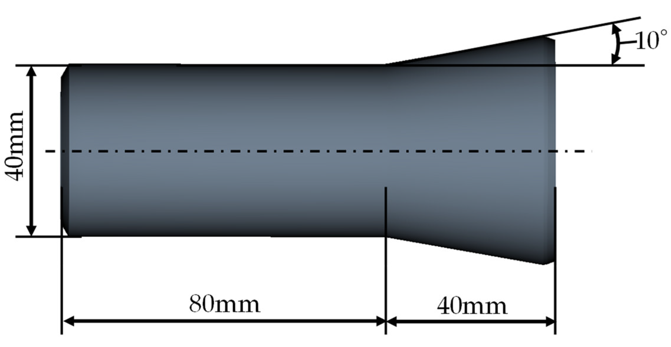
| Taper angle θ/° | 10 | |
| Positioning | Skew angle φ/° | 10, 20 |
| Axial position δ/mm | 10, 15, 20, 25 | |
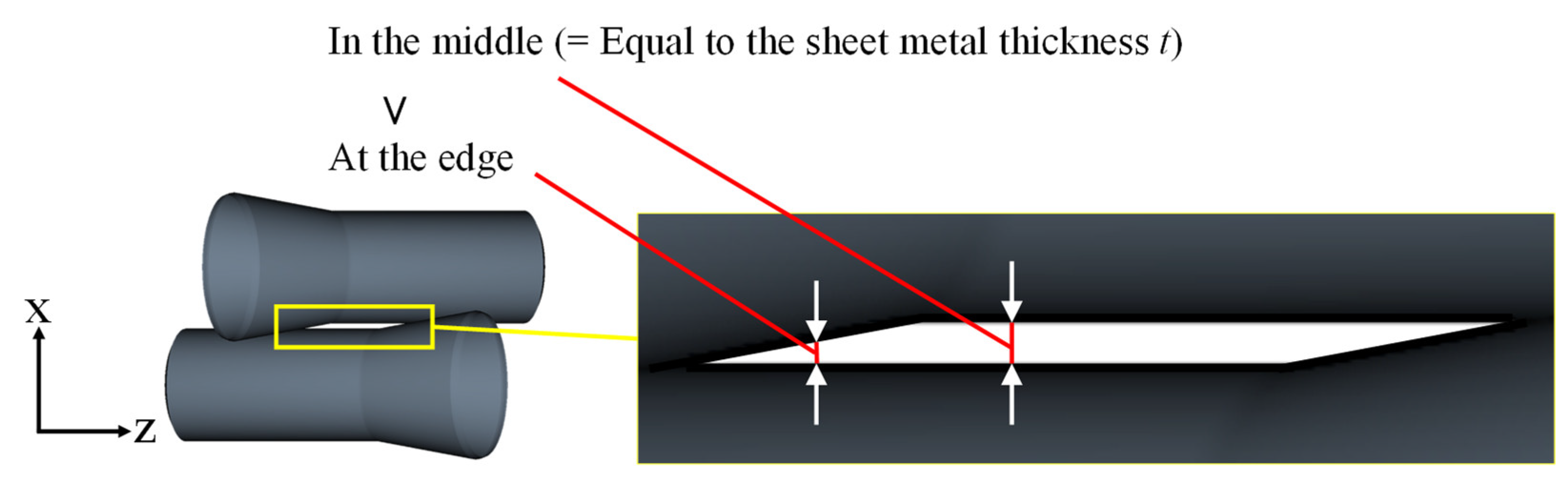
| Gap between rollers h/mm | Equal to sheet metal thickness t |
| Skew Angle φ/° | |||
|---|---|---|---|
| 10 | 20 | ||
| Roll Axial Position δ/mm | 10 | (9.85, 1.74) | (9.40, 3.42) |
| 15 | (14.8, 2.60) | (14.1, 5.13) | |
| 20 | (19.7, 3.47) | (18.8, 6.84) | |
| 25 | (24.6, 4.34) | (23.5, 8.55) | |
| Young’s Modulus E/GPa | Poisson’s Ratio |
|---|---|
| 70.3 | 0.33 |
| Value | 239 | 129 | 1.25 |
| δ/mm | 7 | 8 | 9 | 10 |
|---|---|---|---|---|
| Interfere | F | F | S | S |
| Roll Axial Position δ/mm | 10 | 15 | 20 | 25 |
|---|---|---|---|---|
| Experiment | 0.423 | 0.268 | 0.132 | 0.048 |
| Analysis | 0.499 | 0.310 | 0.168 | 0.033 |
| Skew Angle φ/° | 10 | 20 |
|---|---|---|
| Experiment | 0.299 | 0.132 |
| Analysis | 0.369 | 0.168 |
| Sheet Thickness t/mm | 1 | 2 | 3 |
|---|---|---|---|
| Experiment | 0.088 | 0.132 | 0.158 |
| Analysis | 0.122 | 0.168 | 0.193 |
| Sheet Thickness t/mm | 1 | 2 | 3 |
|---|---|---|---|
| Springback amount Δβx/mm | 9.02 × 10⁻² | 5.11 × 10⁻² | 4.40 × 10⁻² |
| Before Rolling | After Rolling (Straight Section) | After Rolling (Taper Section) | |
|---|---|---|---|
| Arithmetic mean roughness Ra/μm | 0.203 | 1.83 | 1.83 |
| Maximum height roughness Rz/μm | 1.12 | 9.53 | 13.2 |
Disclaimer/Publisher’s Note: The statements, opinions and data contained in all publications are solely those of the individual author(s) and contributor(s) and not of MDPI and/or the editor(s). MDPI and/or the editor(s) disclaim responsibility for any injury to people or property resulting from any ideas, methods, instructions or products referred to in the content. |
© 2023 by the authors. Licensee MDPI, Basel, Switzerland. This article is an open access article distributed under the terms and conditions of the Creative Commons Attribution (CC BY) license (https://creativecommons.org/licenses/by/4.0/).
Share and Cite
Kumar, A.; Kajikawa, S.; Makiyama, T.; Kuboki, T. Effect of Roller Axial Position and Thickness on a Twisted Angle in the Twist Rolling of Aluminum Alloy 1050 Sheet Metal. Metals 2023, 13, 383. https://doi.org/10.3390/met13020383
Kumar A, Kajikawa S, Makiyama T, Kuboki T. Effect of Roller Axial Position and Thickness on a Twisted Angle in the Twist Rolling of Aluminum Alloy 1050 Sheet Metal. Metals. 2023; 13(2):383. https://doi.org/10.3390/met13020383
Chicago/Turabian StyleKumar, Avanish, Shohei Kajikawa, Takahiro Makiyama, and Takashi Kuboki. 2023. "Effect of Roller Axial Position and Thickness on a Twisted Angle in the Twist Rolling of Aluminum Alloy 1050 Sheet Metal" Metals 13, no. 2: 383. https://doi.org/10.3390/met13020383