
Investigation on Mechanical Properties and Oxidation Behavior of 1.2 and 1.7 GPa Grades Coating-Free Press-Hardened Steels

 , , and
Abstract
:1. Introduction
2. Experimental Procedures
2.1. Materials
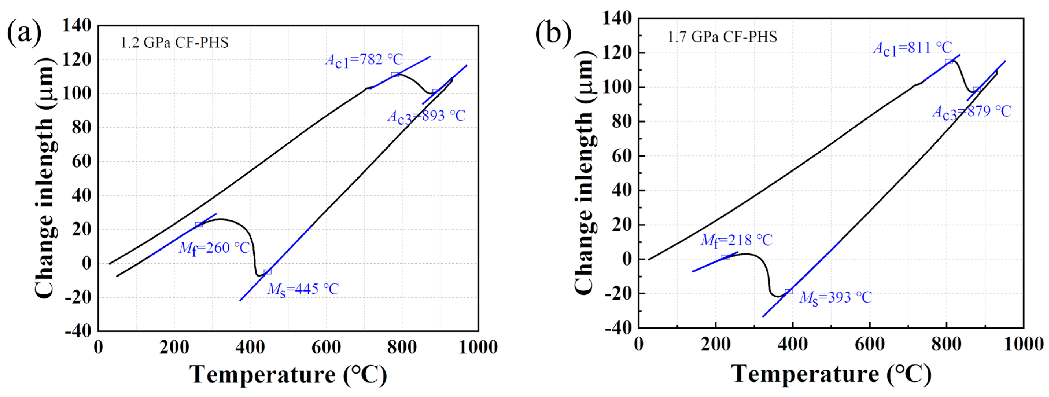
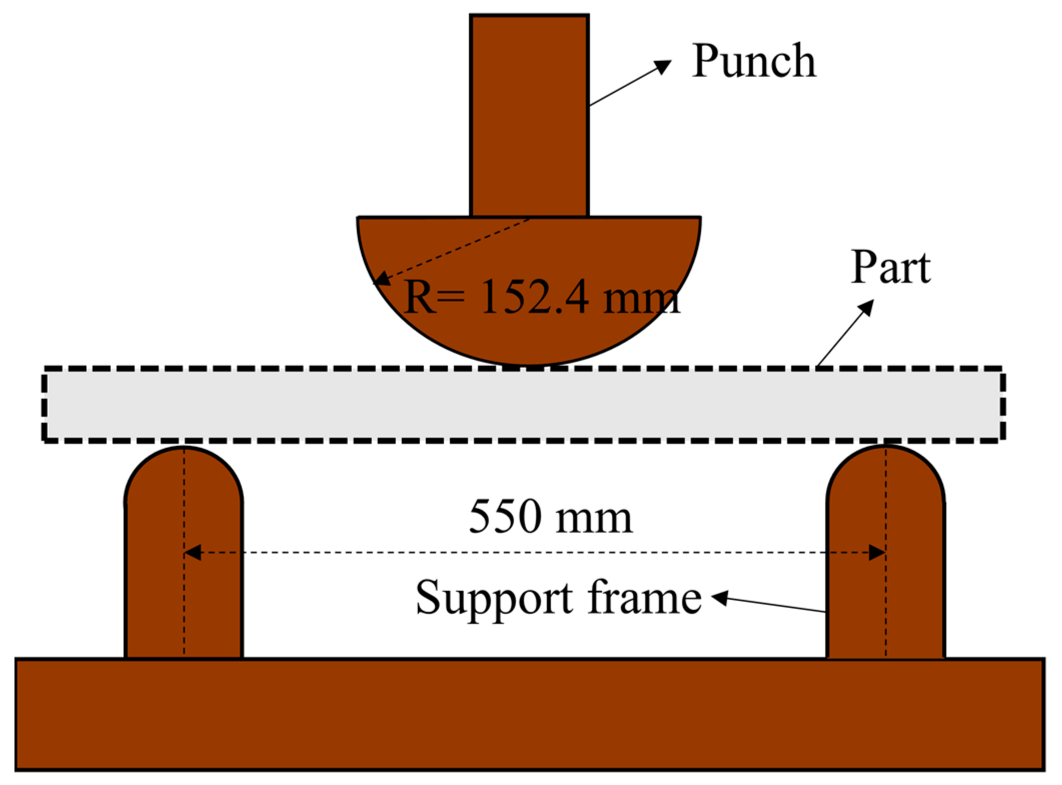
2.2. Hot Forming Process
2.3. Microstructural Analyses and Mechanical Test
3. Results and Discussion
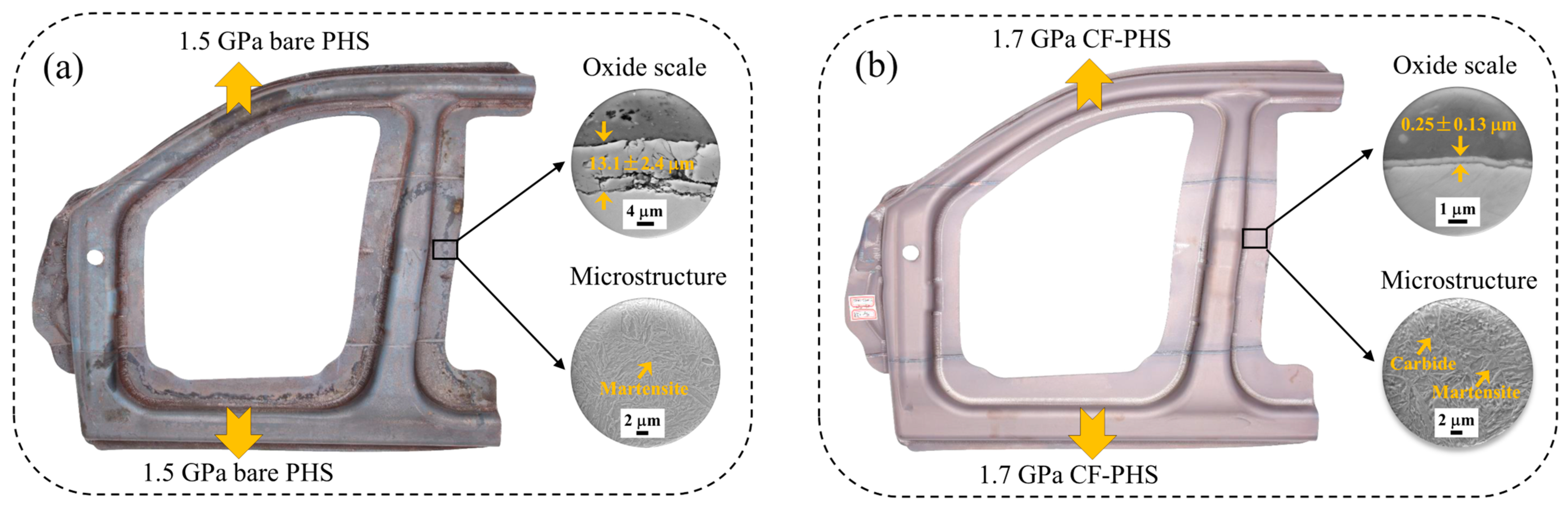
3.1. Oxide Scale
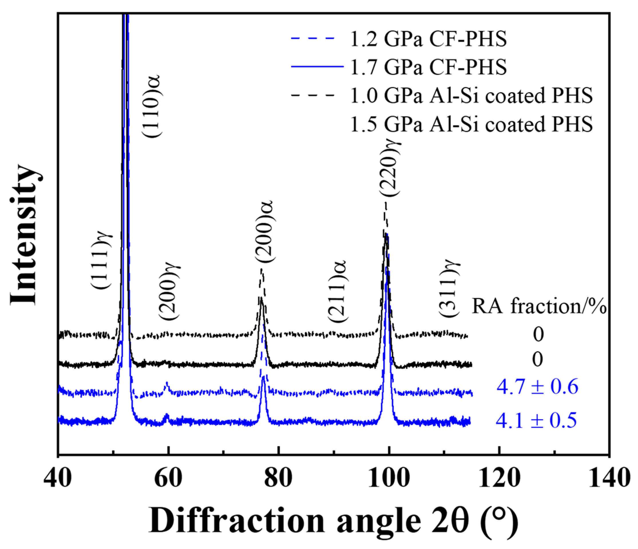
3.2. Microstructure
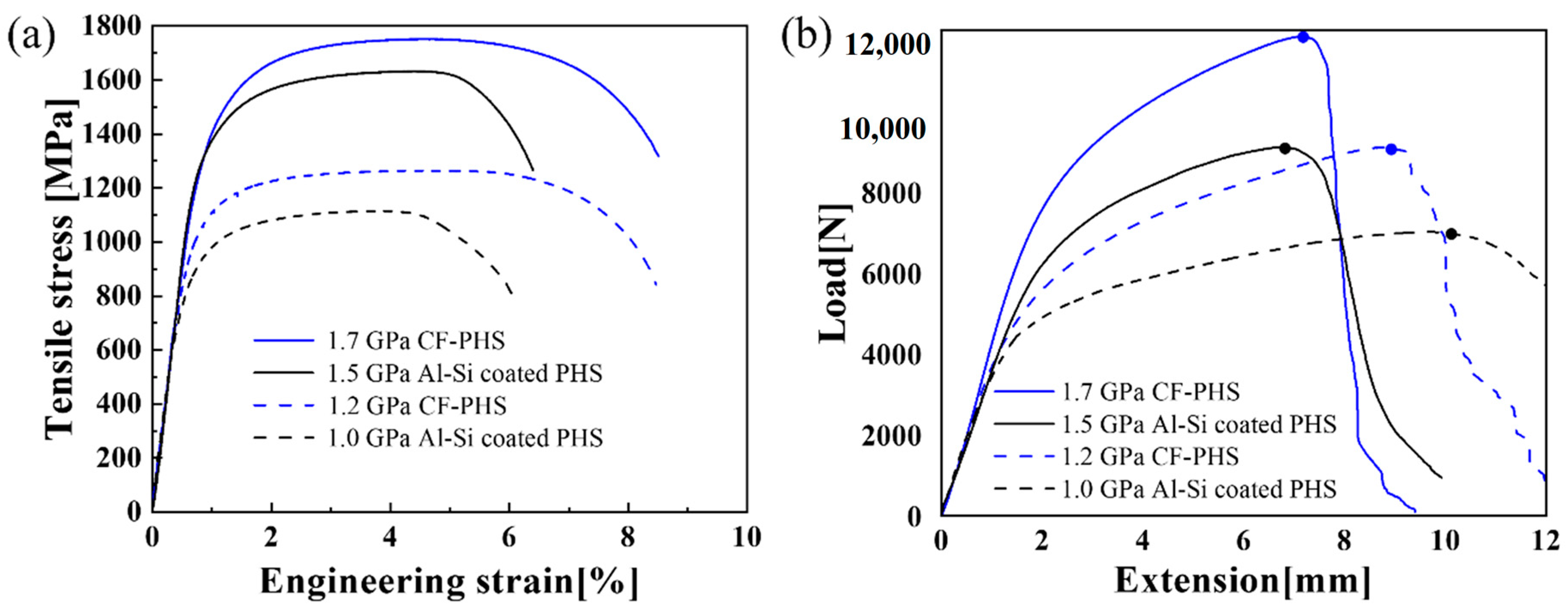
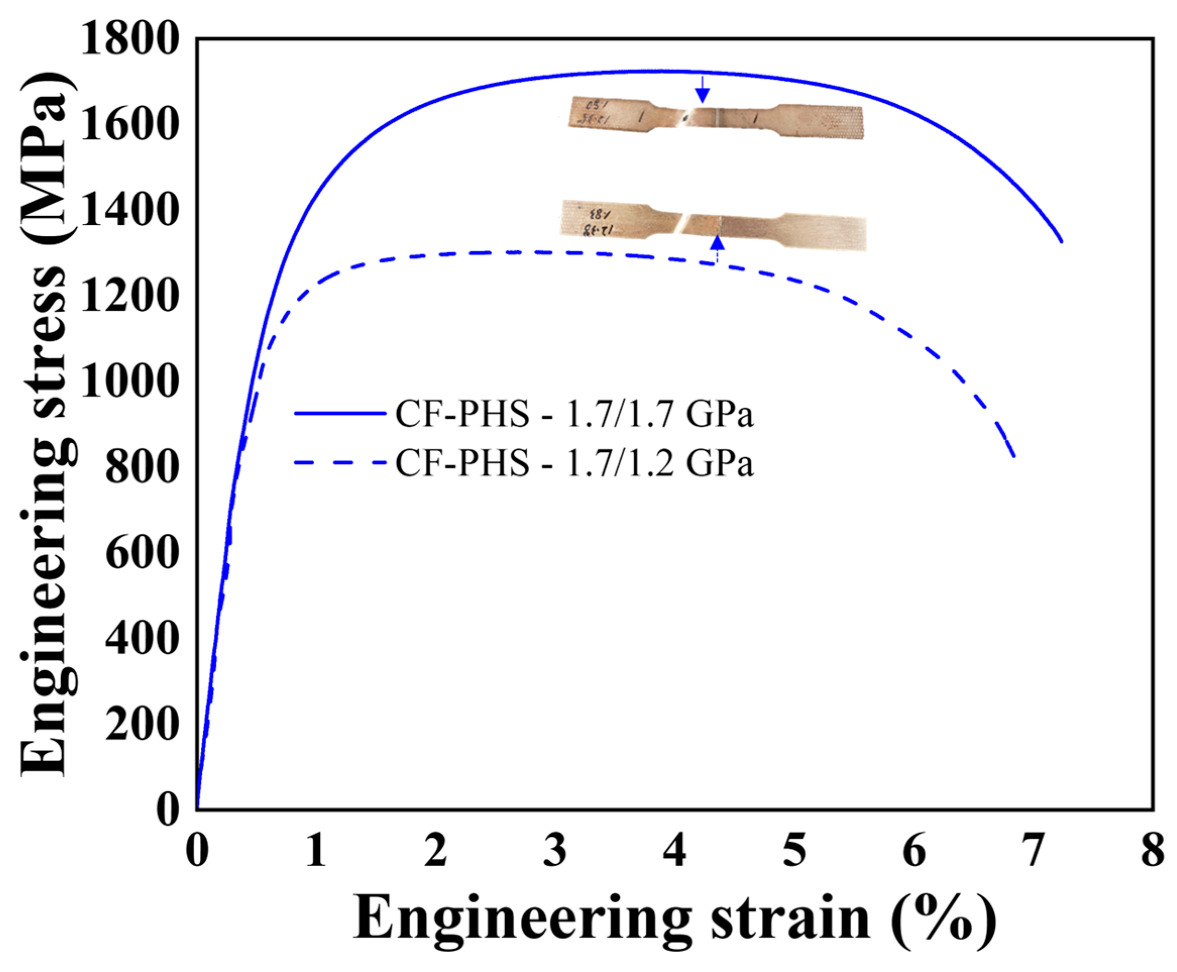
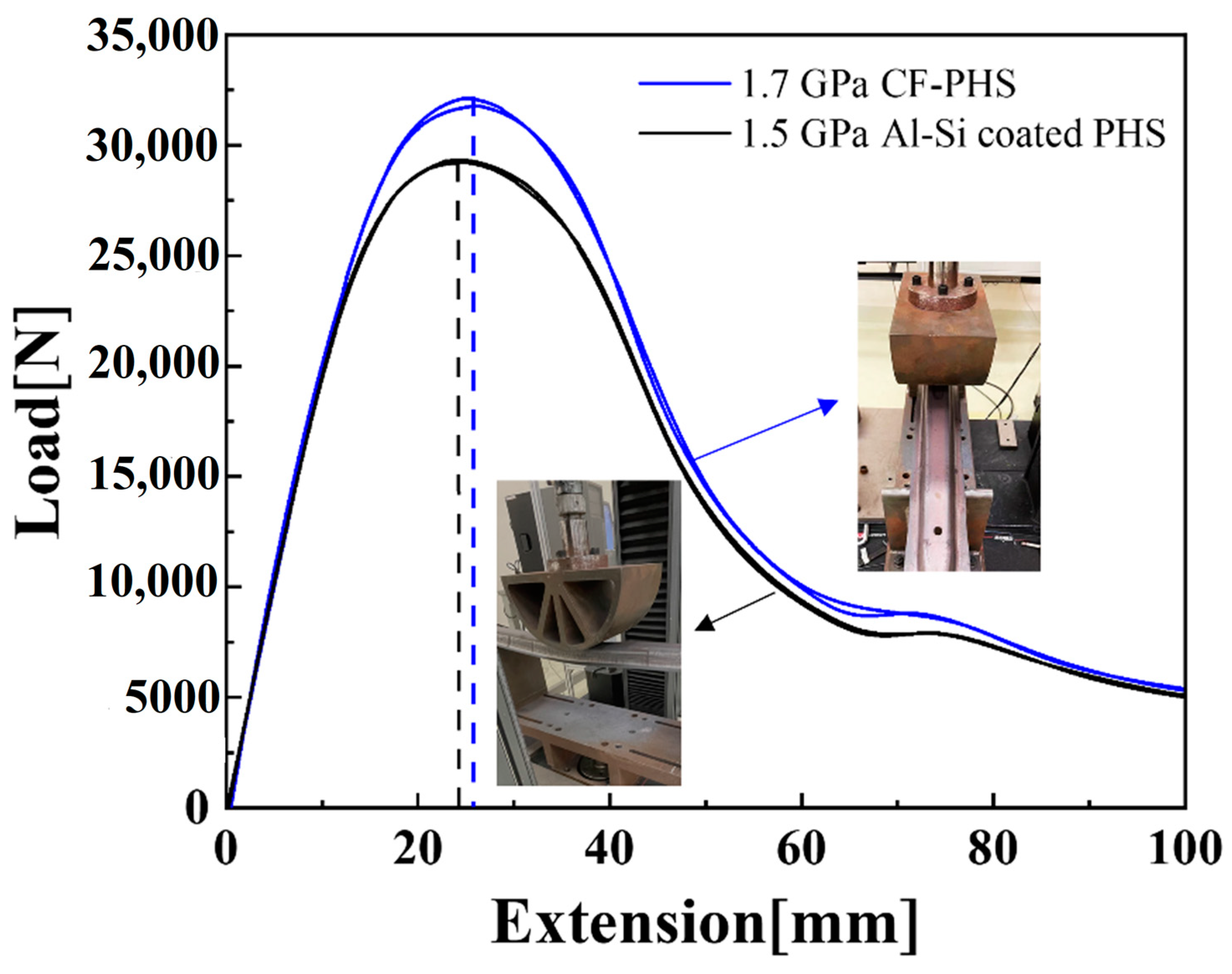
3.3. Tensile Properties and Bending Performance
3.4. Tailored Laser Welding and E-Coat Adhesion Performance
3.5. Mechanical Properties and High-Temperature Oxidation of Components Level
4. Summary
- The tailored Cr, Si, and Mn promote the formation of Cr- and Si-enriched dense surface oxide, leading to an excellent oxidation resistance at high temperatures.
- A primarily martensitic with retained austenite is found in both 1.2 and 1.7 GPa CF-PHS grades after the conventional hot stamping process since the tailored Cr and Si addition promotes the carbon partitioning from martensite to austenite during die quenching. The featured microstructure results in excellent tensile and bending performances at both coupon and component levels.
- Initial laser welding results indicated that direct laser welding can be applied for tailored-welded blank application without using filler wire and/or laser ablation, both of which are currently adopted for the laser welding of Al-Si-coated PHS.
- CF-PHS with an ultra-thin surface oxide has sufficient E-coat adhesion compared to the existing counterparts based on the cross hatch and stone chip testing.
Author Contributions
Funding
Institutional Review Board Statement
Informed Consent Statement
Data Availability Statement
Acknowledgments
Conflicts of Interest
References
- Karbasian, H.; Tekkaya, A. A review on hot stamping. J. Mater. Process. Technol. 2010, 210, 2103–2118. [Google Scholar] [CrossRef]
- Billur, E. Hot Stamping of Ultra High-Strength Steels; Springer: Cham, Switzerland, 2019. [Google Scholar]
- Mori, K.; Bariani, P.; Behrens, B.-A.; Brosius, A.; Bruschi, S.; Maeno, T.; Merklein, M.; Yanagimoto, J. Hot stamping of ultra-high strength steel parts. CIRP Ann. 2017, 66, 755–777. [Google Scholar] [CrossRef]
- Ighodaro, O.; Biro, E.; Zhou, Y. Comparative effects of Al-Si and galvannealed coatings on the properties of resistance spot welded hot stamping steel joints. J. Mater. Process. Technol. 2016, 236, 64–72. [Google Scholar] [CrossRef]
- Wang, Z.; Cao, Z.; Wang, J.; Huang, M. Improving the bending toughness of Al-Si coated press-hardened steel by tailoring coating thickness. Scr. Mater. 2021, 192, 19–25. [Google Scholar] [CrossRef]
- Santacreu, P.-O.; Badinier, G.; Moreau, J.-B.; Herbelin, J.-M. Fatigue Properties of a New Martensitic Stainless Steel for Hot Stamped Chassis Parts. SAE Tech. Pap. 2015. [Google Scholar] [CrossRef]
- Wang, L.J.; Liu, C.M. Martensitic Stainless Steel as Alternative for Hot Stamping Steel with High Product of Strength and Ductility. Adv. Mater. Res. 2015, 1063, 37–41. [Google Scholar] [CrossRef]
- Li, S.; Wen, P.; Li, S.; Song, W.; Wang, Y.; Luo, H. A novel medium-Mn steel with superior mechanical properties and marginal oxidization after press hardening. Acta Mater. 2021, 205, 116567. [Google Scholar] [CrossRef]
- Hou, Z.; Opitz, T.; Xiong, X.; Zhao, X.; Yi, H. Bake-partitioning in a press-hardening steel. Scr. Mater. 2019, 162, 492–496. [Google Scholar] [CrossRef]
- Lu, Q.; Eizadjou, M.; Wang, J.; Ceguerra, A.; Ringer, S.; Zhan, H.; Wang, L.; Lai, Q. Medium-Mn Martensitic Steel Ductilized by Baking. Met. Mater. Trans. A 2019, 50, 4067–4074. [Google Scholar] [CrossRef]
- Cai, X.; Ding, S.; Jin, S.; Xu, L.; Liu, G.; Sun, B.; Shen, T. Superior high-temperature oxidation resistance of nanocrystalline 304 austenitic stainless steel containing a small amount of Si. Scr. Mater. 2021, 204, 114155. [Google Scholar] [CrossRef]
- Zhang, L.; Yan, W.; Shi, Q.; Li, Y.; Shan, Y.; Yang, K. Silicon enhances high temperature oxidation resistance of SIMP steel at 700 °C. Corros. Sci. 2020, 167, 108519. [Google Scholar] [CrossRef]
- Yun, D.W.; Seo, S.; Jeong, H.; Yoo, Y. The effects of the minor alloying elements Al, Si and Mn on the cyclic oxidation of Ni–Cr–W–Mo alloys. Corros. Sci. 2014, 83, 176–188. [Google Scholar] [CrossRef]
- Tökei, Z.; Viefhaus, H.; Grabke, H. Initial stages of oxidation of a 9CrMoV-steel: Role of segregation and martensite laths. Appl. Surf. Sci. 2000, 165, 23–33. [Google Scholar] [CrossRef]
- Wang, S.; Wu, Y.; Ni, C.; Niu, Y. The effect of Si additions on the high temperature oxidation of a ternary Ni–10Cr–4Al alloy in 1atm O2 at 1100 °C. Corros. Sci. 2009, 51, 511–517. [Google Scholar] [CrossRef]
- Chen, S.; Jin, X.; Rong, L. Improvement in High Temperature Oxidation Resistance of 9% Cr Ferritic–Martensitic Steel by Enhanced Diffusion of Mn. Oxid. Met. 2016, 85, 189–203. [Google Scholar] [CrossRef]
- Jin, X.; Chen, S.; Rong, L. Effects of Mn on the mechanical properties and high temperature oxidation of 9Cr2WVTa steel. J. Nucl. Mater. 2017, 494, 103–113. [Google Scholar] [CrossRef]
- Fischer, F.; Reisner, G.; Werner, E.; Tanaka, K.; Cailletaud, G.; Antretter, T. A new view on transformation induced plasticity (TRIP). Int. J. Plast. 2000, 16, 723–748. [Google Scholar] [CrossRef]
- Zhang, C.; Xiong, Z.; Yang, D.; Cheng, X. Heterogeneous quenching and partitioning from manganese-partitioned pearlite: Retained austenite modification and formability improvement. Acta Mater. 2022, 235, 118060. [Google Scholar] [CrossRef]
- Chai, Z.; Lu, Q.; Hu, J.; Wang, L.; Wang, Z.; Wang, J.; Xu, W. Effect of retained austenite on the fracture behavior of a novel press-hardened steel. J. Mater. Sci. Technol. 2023, 135, 34–45. [Google Scholar] [CrossRef]
- Wei, X.; Chai, Z.; Lu, Q.; Hu, J.; Liu, Z.; Lai, Q.; Wang, J.; Xu, W. Cr-alloyed novel press-hardening steel with superior combination of strength and ductility. Mater. Sci. Eng. A 2021, 819, 141461. [Google Scholar] [CrossRef]
- Chang, Z.; Li, Y.; Wu, D. Enhanced ductility and toughness in 2000 MPa grade press hardening steels by auto-tempering. Mater. Sci. Eng. A 2020, 784, 139342. [Google Scholar] [CrossRef]
- Linke, B.M.; Gerber, T.; Hatscher, A.; Salvatori, I.; Aranguren, I.; Arribas, M. Impact of Si on Microstructure and Mechanical Properties of 22MnB5 Hot Stamping Steel Treated by Quenching & Partitioning (Q&P). Met. Mater. Trans. A 2018, 49, 54–65. [Google Scholar] [CrossRef]
- Kirchner, G.; Nishizawa, T.; Uhrenius, B. The distribution of chromium between ferrite and austenite and the thermodynamics of the α/γ equilibrium in the Fe-Cr and Fe-Mn Systems. Met. Mater. Trans. B 1973, 4, 167–174. [Google Scholar] [CrossRef]
- Pierce, D.; Coughlin, D.; Clarke, K.; De Moor, E.; Poplawsky, J.; Williamson, D.; Mazumder, B.; Speer, J.; Hood, A.; Clarke, A. Microstructural evolution during quenching and partitioning of 0.2C-1.5Mn-1.3Si steels with Cr or Ni additions. Acta Mater. 2018, 151, 454–469. [Google Scholar] [CrossRef]
- Kinoshita, Y.; Yardley, V.; Tsurekawa, S. Relation between microstructures of martensite and prior austenite in 12 wt% Cr ferritic steel. J. Mater. Sci. 2011, 46, 4261–4269. [Google Scholar] [CrossRef]
- Kitahara, H.; Ueji, R.; Tsuji, N.; Minamino, Y. Crystallographic features of lath martensite in low-carbon steel. Acta Mater. 2006, 54, 1279–1288. [Google Scholar] [CrossRef]
- Atkins, E. Elements of X-ray Diffraction. Phys. Bull. 1978, 29, 572. [Google Scholar] [CrossRef]
- Noder, J.; Abedini, A.; Butcher, C. Evaluation of the VDA 238–100 Tight Radius Bend Test for Plane Strain Fracture Characterization of Automotive Sheet Metals. Exp. Mech. 2020, 60, 787–800. [Google Scholar] [CrossRef]
- Kong, L.; Liu, Y.; Liu, J.; Song, Y.; Li, S.; Zhang, R.; Li, T.; Liang, Y. The influence of chromium on the pearlite-austenite transformation kinetics of the Fe–Cr–C ternary steels. J. Alloys Compd. 2015, 648, 494–499. [Google Scholar] [CrossRef]
- Jung, S.; Sohn, S.S.; Jo, Y.H.; Choi, W.-M.; Lee, B.-J.; Oh, Y.-J.; Kim, G.-Y.; Jang, S.; Lee, S. Effects of Cr and Nb addition on high-temperature tensile properties in austenitic cast steels used for turbo-charger application. Mater. Sci. Eng. A 2016, 677, 316–324. [Google Scholar] [CrossRef]
- Yoo, J.; Jo, M.C.; Bian, J.; Sohn, S.S.; Lee, S. Effects of Nb or (Nb + Mo) alloying on Charpy impact, bending, and delayed fracture properties in 1.9-GPa-grade press hardening steels. Mater. Charact. 2021, 176, 111133. [Google Scholar] [CrossRef]
- Chen, W.; Gao, P.; Wang, S.; Zhao, X.; Zhao, Z. Strengthening mechanisms of Nb and V microalloying high strength hot-stamped steel. Mater. Sci. Eng. A 2020, 797, 140115. [Google Scholar] [CrossRef]
- Morito, S.; Yoshida, H.; Maki, T.; Huang, X. Effect of block size on the strength of lath martensite in low carbon steels. Mater. Sci. Eng. A 2006, 438–440, 237–240. [Google Scholar] [CrossRef]


| Steel Grade | C | Mn | Cr | Si | Nb | B | Ti | Fe |
|---|---|---|---|---|---|---|---|---|
| 1.2 GPa CF-PHS | 0.08 | 1.5–2.5 | ≤2.5 | ≤1.5 | 0.025 | - | - | Bal. |
| 1.7 GPa CF-PHS | 0.20 | 0.8–1.4 | ≤2.5 | ≤2.5 | 0.025 | - | - | Bal. |
| 1.0 GPa Al-Si coated PHS | 0.10 | 1.80 | - | 0.30 | 0.04 | 0.003 | 0.02 | Bal. |
| 1.5 GPa Al-Si coated PHS | 0.23 | 1.2 | 0.16 | 0.22 | - | 0.005 | 0.04 | Bal. |
| Steel | UTS (MPa) | TEL (%) | Peak Force (N) | Bending Angle (°) |
|---|---|---|---|---|
| 1.2 GPa CF-PHS | 1236 ± 6 | 8.4 ± 0.5 | 9104 ± 53 | 79 ± 1.2 |
| 1.7 GPa CF-PHS | 1731 ± 8 | 8.5 ± 0.4 | 11,844 ± 87 | 60 ± 0.6 |
| 1.0 GPa Al-Si-coated PHS | 1086 ± 4 | 6.5 ± 0.3 | 7015 ± 68 | 88 ± 0.5 |
| 1.5 GPa Al-Si-coated PHS | 1552 ± 6 | 6.2 ± 0.5 | 9112 ± 82 | 57 ± 0.9 |
Disclaimer/Publisher’s Note: The statements, opinions and data contained in all publications are solely those of the individual author(s) and contributor(s) and not of MDPI and/or the editor(s). MDPI and/or the editor(s) disclaim responsibility for any injury to people or property resulting from any ideas, methods, instructions or products referred to in the content. |
© 2023 by the authors. Licensee MDPI, Basel, Switzerland. This article is an open access article distributed under the terms and conditions of the Creative Commons Attribution (CC BY) license (https://creativecommons.org/licenses/by/4.0/).
Share and Cite
Chai, Z.; Lu, Q.; Tedesco, S.; Shi, M.; Coryell, J.; Reini, L.; Lai, Q.; Wang, J.; Wang, L.; Xu, W. Investigation on Mechanical Properties and Oxidation Behavior of 1.2 and 1.7 GPa Grades Coating-Free Press-Hardened Steels. Metals 2023, 13, 489. https://doi.org/10.3390/met13030489
Chai Z, Lu Q, Tedesco S, Shi M, Coryell J, Reini L, Lai Q, Wang J, Wang L, Xu W. Investigation on Mechanical Properties and Oxidation Behavior of 1.2 and 1.7 GPa Grades Coating-Free Press-Hardened Steels. Metals. 2023; 13(3):489. https://doi.org/10.3390/met13030489
Chicago/Turabian StyleChai, Zhisong, Qi Lu, Sarah Tedesco, Mingfeng Shi, Jason Coryell, Luke Reini, Qingquan Lai, Jianfeng Wang, Lingyu Wang, and Wei Xu. 2023. "Investigation on Mechanical Properties and Oxidation Behavior of 1.2 and 1.7 GPa Grades Coating-Free Press-Hardened Steels" Metals 13, no. 3: 489. https://doi.org/10.3390/met13030489
APA StyleChai, Z., Lu, Q., Tedesco, S., Shi, M., Coryell, J., Reini, L., Lai, Q., Wang, J., Wang, L., & Xu, W. (2023). Investigation on Mechanical Properties and Oxidation Behavior of 1.2 and 1.7 GPa Grades Coating-Free Press-Hardened Steels. Metals, 13(3), 489. https://doi.org/10.3390/met13030489