Article

Short-Flow Rolling Process and Heat Treatment of Seamless Titanium Alloy Tube

1
School of Mechanical Engineering, Taiyuan University of Science and Technology, Taiyuan 030024, China
2
College of Material Science and Engineering, Taiyuan University of Science and Technology, Taiyuan 030024, China
*
Author to whom correspondence should be addressed.
Metals 2023, 13(3), 527; https://doi.org/10.3390/met13030527
Submission received: 12 February 2023 / Revised: 2 March 2023 / Accepted: 4 March 2023 / Published: 6 March 2023
(This article belongs to the Section Metal Casting, Forming and Heat Treatment)

Abstract

:
In view of the material characteristics of titanium alloys, such as their capability to quickly cool down and their poor machinability, in this study, we combined a new production mode for seamless tube rolling (tandem skew rolling, TSR) with titanium alloy materials and conducted systematic research. The most suitable parameters for titanium alloy rolling were determined from the unit parameters using finite-element software and an analysis of the changing laws of stress-strain, temperature, speed and tension during the rolling process. A rolling experiment was completed in the tandem skew rolling unit. Seamless titanium alloy (TC4ELI) tubes with uniform wall thickness were successfully produced and a metallurgical heat-treatment experiment was carried out. The results show that the seamless titanium alloy tubes prepared using the TSR process have a high degree of dimensional precision (the outer diameter is approximately 38.7 mm, the wall thickness is approximately 3.9 mm and the axial extension is 2.9 times) and the tube after heat treatment still presented a basketweave structure. Furthermore, the hardness level of the seamless titanium alloy tubes was improved. It can be concluded that the TSR process with a short flow is suitable for the mass production of seamless titanium alloy tubes.

1. Introduction

The rare metal titanium has always attracted worldwide attention because of its huge reserves, but its application is limited due to mining constraints and high refining costs [1]. In recent years, with improvements in titanium mining and refining technology, titanium and titanium alloy products have increasingly appeared in industrial production. Among all kinds of products, seamless titanium alloy tubes have been used in various applications in many industries, such as the aerospace, medical equipment and petrochemical industries, because of titanium’s excellent mechanical and corrosion resistance. Therefore, studies on the production processes and mechanical properties of seamless titanium alloy tubes have gradually become a hot topic [2].
Up until now, the traditional production methods for seamless titanium alloy tubes have included extrusion, drawing, spinning and rolling. Seamless titanium alloy tubes produced by extrusion and drawing have a superior quality; however, the high tooling-loss characteristics and low production efficiency lead to a high production cost [3]. Although spinning is simple in terms of equipment and tooling, strong spinning is especially beneficial to the production of titanium alloy; however, its production efficiency is low and it is only suitable for trial and small batch production [4]. The rolling process has gradually become the main method in the production of seamless titanium alloy tubes due to the process’s high efficiency, high precision, and low cost, and consequently, it has been greatly promoted and developed all over the world [5].
Wang Chaofeng et al. [6] successfully prepared a φ101.6 mm × 10 mm tube by heating Ti64ELI and adopting a floating continuous tube rolling process. Wang He et al. [7] produced a φ610 mm × 30 mm × 6000 mm large-diameter TC4 seamless titanium alloy tube with good comprehensive performance through the process of combining forging and extrusion in a periodic tube-rolling mill. Zhang Bing et al. [8] selected typical materials for thermal simulation experiments, developed a φ75 mm seamless titanium alloy tube-rolling process, and obtained a very strong and resistant seamless titanium alloy tube through positive heat treatment. Yang Qi et al. [9] obtained an ideal radial weave when Q > 2.0 and produced a Ti-3Al-2.5 V tube through cold-rolling process parameter selection and weave analysis. Bayona et al. [10] prepared a Ti-3Al-2.5 V seamless tube with Pilger cold rolling, measured the recrystallization volume fraction after different annealing conditions using electron backscattered diffraction, and analyzed the influence of recrystallization on the tensile and anisotropic properties of the tube. Zhang Fuping et al. [11] analyzed the influence of the extrusion ratio and extrusion temperature on the microstructure of the tube and prepared a small-diameter TA22 tube with excellent tensile properties through appropriate rolling process parameters.
The above discussion shows that the current rolling process (including hot rolling and cold rolling) is usually used as a conventional production method. These processes are mainly used to produce ordinary carbon steel and alloy steel. Therefore, combining the material properties of titanium alloy, such as its ability to cool quickly and its high deformation resistance, our research team developed a new short-flow process for seamless tube rolling. This process combines piercing and tube rolling together so that the high-temperature bar can undergo continuous plastic deformation in a short amount of time [12]. It is called tandem skew rolling as it consists of a three-roller cross-piercing part and a three-roller cross-rolling part. Starting from a numerical simulation, we analyzed the rolling process and carried out field rolling experiments and heat treatment research, so as to lay the theoretical foundation and provide practical experience for further development of the production of seamless titanium alloy tubes using the TSR process.

2. Process Introduction and Finite-Element Analysis

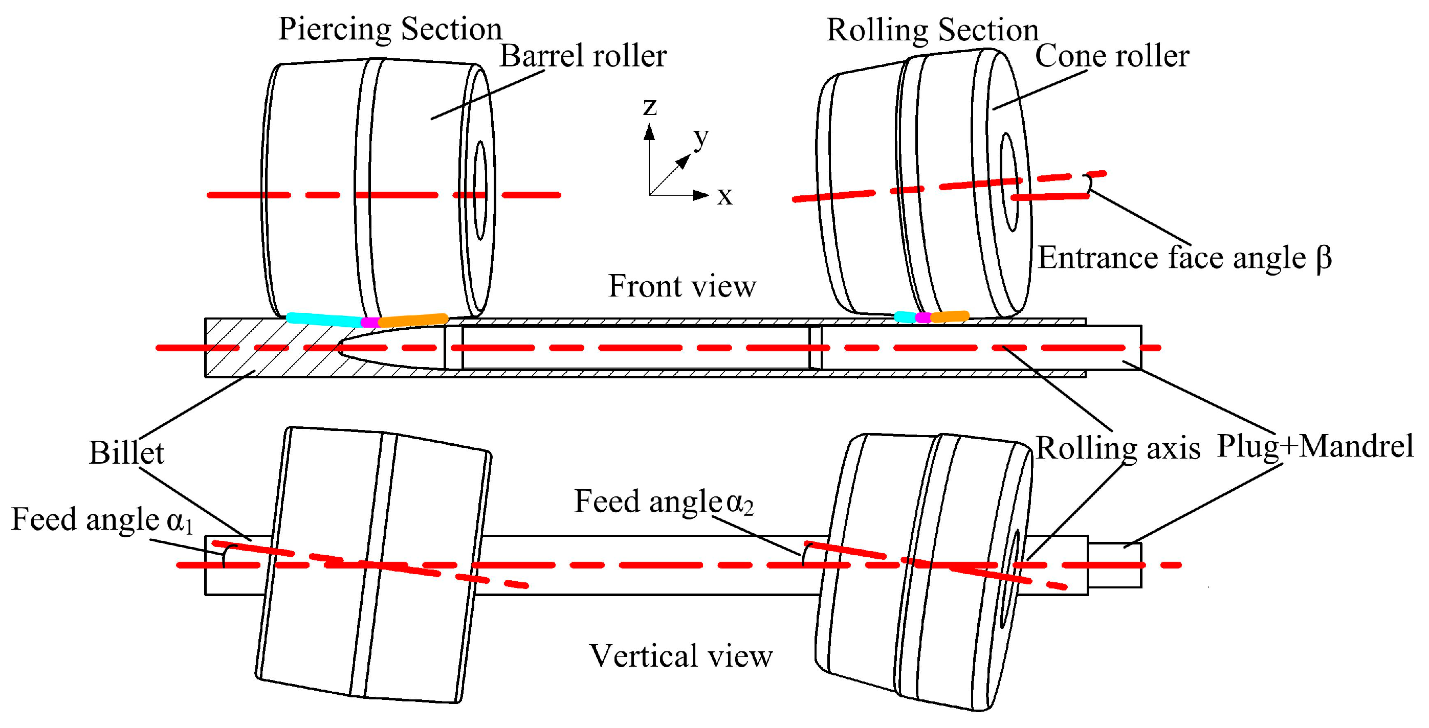
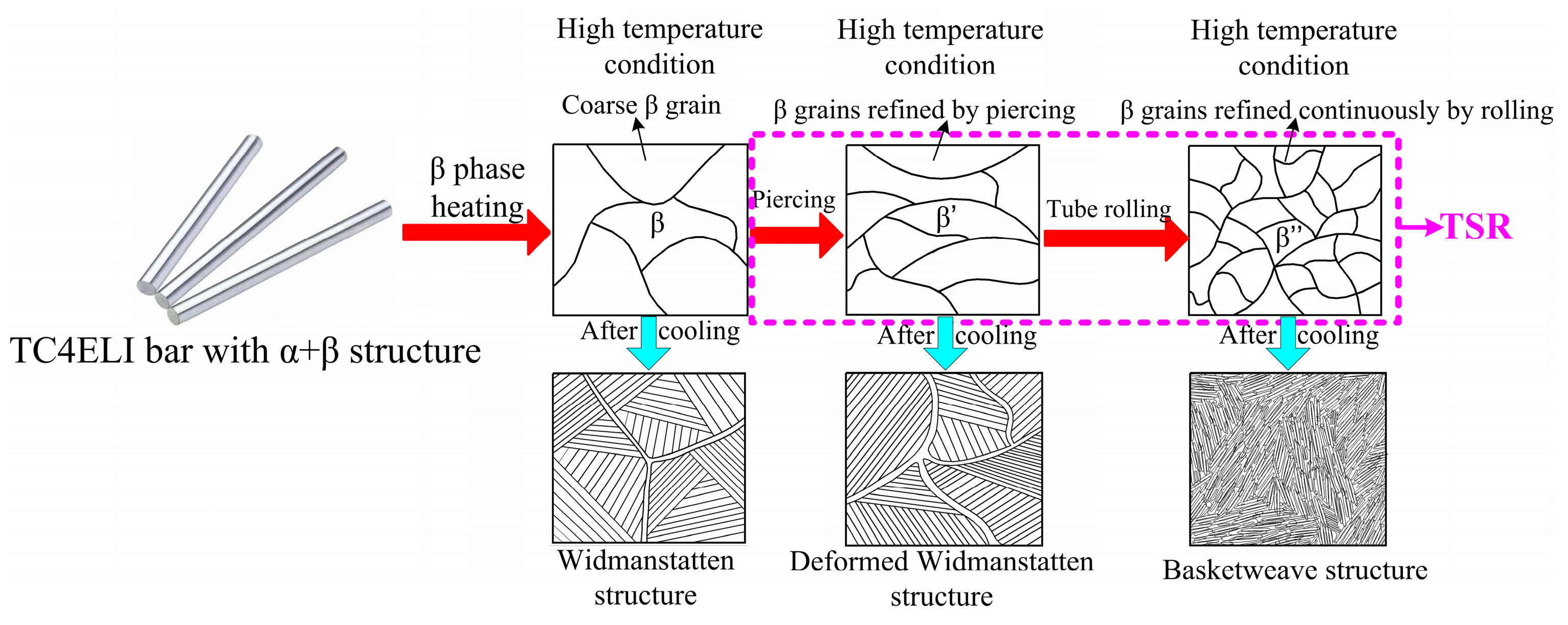
2.1. Process Principle

The piercing process is completed with three rollers around the plug. The rollers are barrel-shaped and uniformly distributed around the plug in a triangular formation. The rolling process is completed with three rollers around the mandrel, and the rollers are conical and distributed around the mandrel in a triangular formation. The plug and mandrel are connected through threads. As shown in Figure 1, in order to demonstrate these principles, the two deformation processes are shown using only one roller.
The piercing part adopts the three-roll cross-piercing process. In order to bite the bar smoothly, the rollers swing in the XY plane to form feed angle α1. The rolling part adopts the three-roller cross-rolling process, and in addition to the feed angle α2, it also has an entrance face angle β in the XZ plane. Following piercing, the tube enters the rolling area to complete the diameter reduction and wall reduction. The colored lines in the figure indicate the deformation zones. The areas with different functions comprehensively complete the forming function of the TSR process. Through several experiments, we determined the adjustable range of each parameter for φ40 mm bars, as shown in Table 1 [13]. The piercing rollers were driven by an AC motor and rotated counterclockwise at a constant speed. The entrance face angle of the tube rolling part was kept constant at 4°.

2.2. Finite-Element Model and Selection of Key Parameters

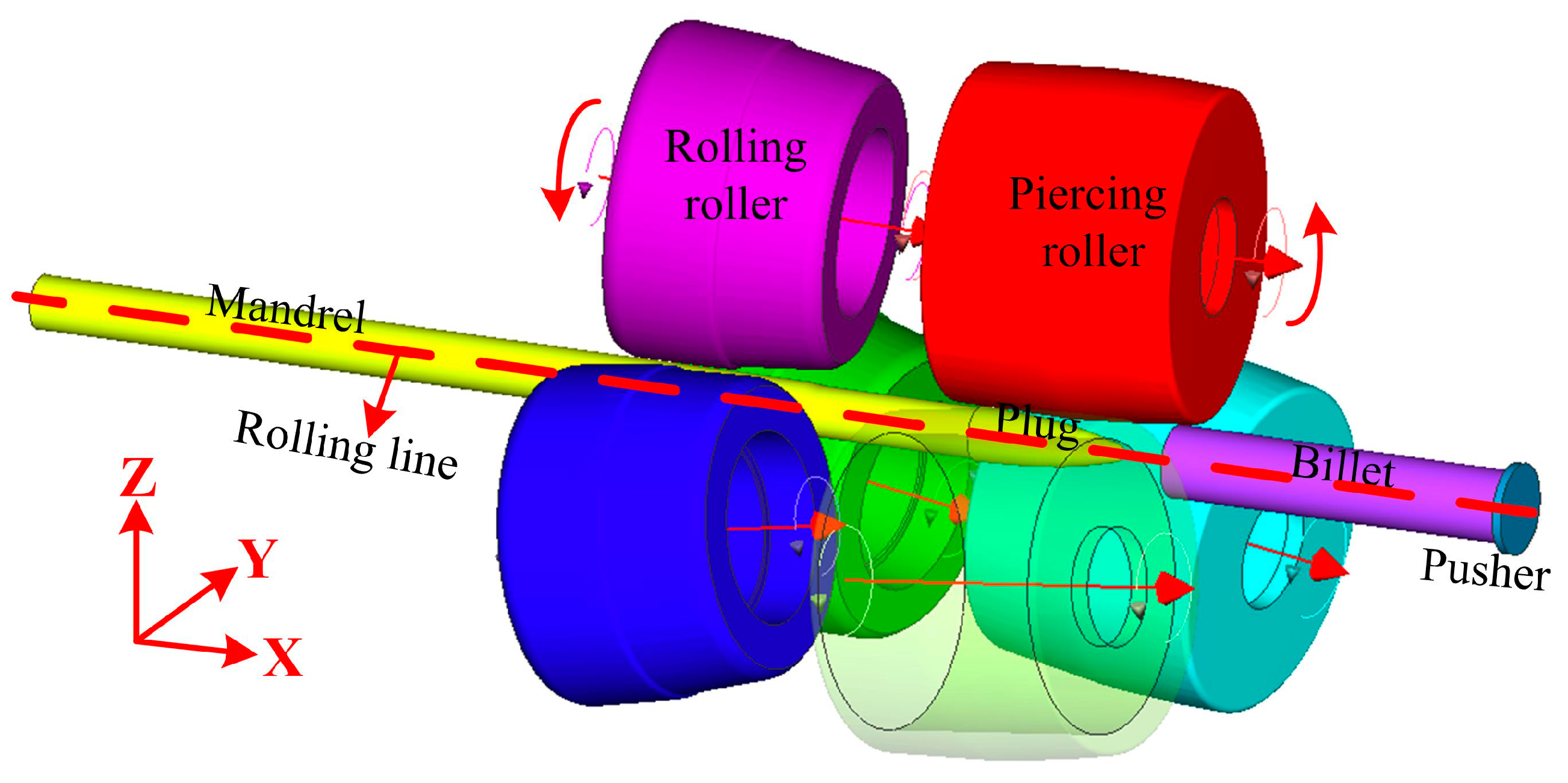
2.2.1. Model Building

The solid model in this study was constructed using three-dimensional modeling software, imported into the finite element simulation software and then the tube rolling module was selected [14]. The distance between two sets of rollers in the model is somewhat shortened in order to improve the computing efficiency, but this does not affect the process and forming accuracy. The simulation model is shown in Figure 2.
The plug and mandrel are arranged along the X direction in the model. The bar advances along the X-axis during the rolling process. Once the model was imported into the simulation software, all of the tools and dies involved in deformation were set as rigid bodies except for the workpiece. The temperature of all dies was set at 150 °C and the ambient temperature was set to 20 °C. The bar mesh was selected as a hexahedral mesh with a cell size of 1.3 mm and a quantity of approximately 35,000. The friction type was Coulomb friction, the friction coefficient between the bar and roller was 0.8 and the friction coefficient between the bar and plug was 0.5. The element composition of the TC4ELI bar selected in the finite element simulation is shown in Table 2.
The fundamental mechanical characteristics of the experimental materials were obtained through the hot compression experiment and imported into the simulation software, whose flow curves are shown in Figure 3.

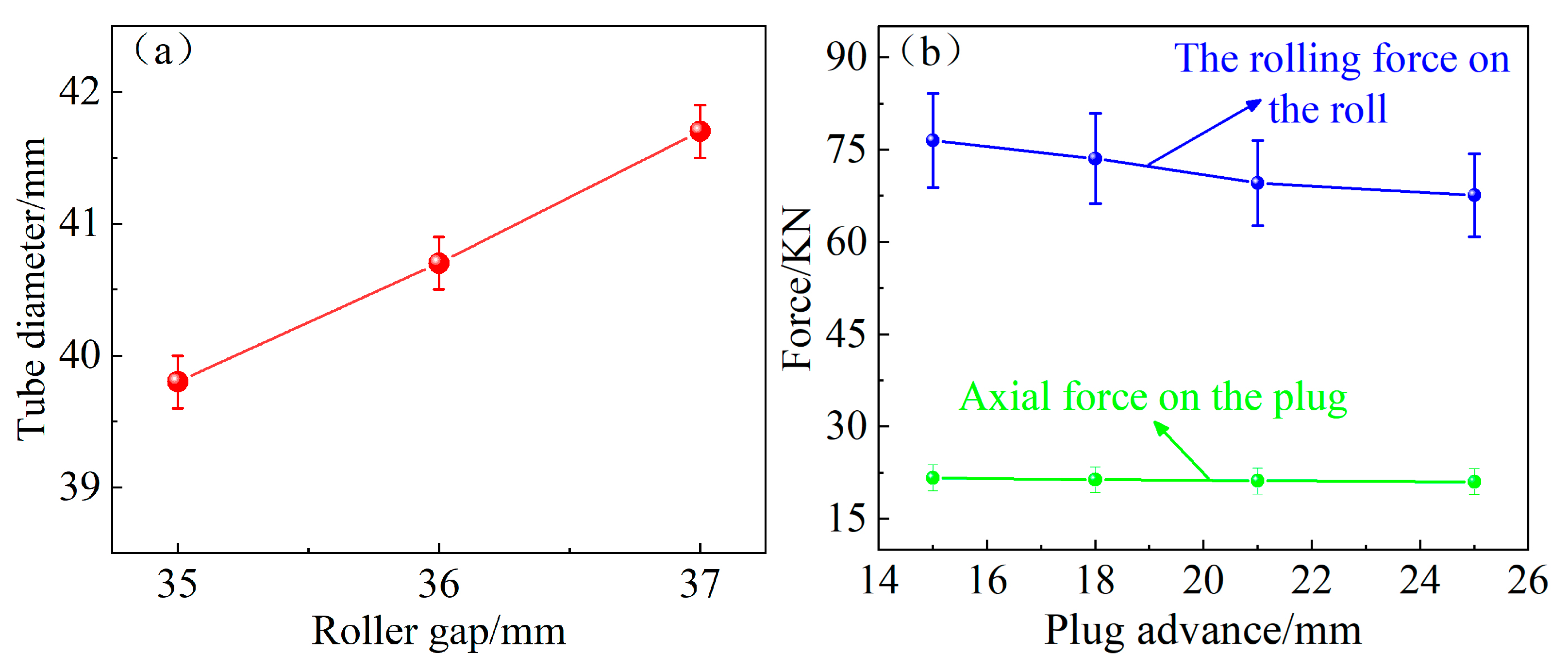
2.2.2. Key Parameter Selection

Temperature is one of the key factors in the thermal processing of titanium alloys. The choice of the initial rolling temperature is critical. The deformation resistance will be too large if the temperature is low, such as below 1000 °C, and the mill life will be greatly affected. If the temperature is too high, such as 1050 °C or higher, although the deformation resistance is reduced, the bar over-burning phenomenon may occur, which will eventually have an impact on the properties of the tube. Therefore, 1025 °C was selected as the initial rolling temperature used in the simulation and experiments in this study.
Piercing in the TSR process precedes rolling. The premise of success is the smooth completion of the piercing process. That is to say, if there is an abnormality in the piercing stage, it is likely to cause interruption and failure of the TSR process. Due to the inherent material properties of titanium alloy, such as its poor fluidity and high deformation resistance, the parameters in Table 1 may not be fully applicable to titanium alloy, so it was necessary to select the key parameters through finite-element simulation [15].
It can be seen from Figure 4a that as the roller gap increases, the amount of roller pressure on the bar gradually decreases and the outer diameter of the tube after piercing gradually increases. The 34 mm roller gap can achieve bar biting but cause mesh cracking, and in this case, the calculation will not converge due to mesh cracking. Although the 37 mm roller gap can successfully produce a tube, due to the small amount of pressure, it may not be able to overcome the axial resistance of the plug in real, complex production. Therefore, excluding these risky parameters, 35 mm and 36 mm can be used as the roller gap for titanium alloy piercing.
In Figure 4b, when the plug advance increases, the rolling force borne by the roller gradually decreases and the average value of the axial force remains stable. If the plug advance is too small, the unit will bear a large rolling force, which will cause serious equipment consumption. If the plug advance is too large, the gap between the plug and the roller is too small, which will increase the probability of jamming in the titanium alloy and other metals that do not flow easily. Therefore, following a comprehensive consideration of the mill equipment and its success rate, 21 mm was selected as the plug advance during titanium alloy piercing.
The key factor affecting the rolling success in the tube rolling part is the roller speed. The roller is driven by three DC motors with a maximum speed of 1000 r/min and a speed ratio of 5:1 reducer, so the maximum speed of the rollers is 200 rpm. In this study, 175 rpm (close to 169 rpm), 185 rpm (greater than 169 rpm) and 195 rpm (close to the maximum speed of the motor) were selected to match the piercing speed (169 rpm). The tube variation trend is shown in Figure 5.
Figure 5 shows the influence trend of the rolling speed on the wall thickness and elongation, respectively. The design concept of the TSR process is that the rolling speed is greater than the piercing speed so that the tension rolling effect can be formed, which is conducive to the forming and extension of the tube. All three rotational speeds can complete the TSR process; the wall thickness of the seamless tubes will be reduced, and the elongation will increase with the increase in the rolling speed. Elongation refers to the ratio of the total length of the tube to the length of the billet after rolling. The greater the elongation, the greater the plastic deformation of the tube and the smaller the grain size.
In order to avoid material stacking and obtain the maximum elongation effect, we chose 195 rpm as the rolling speed. Based on the above analysis, the criterion for parameter selection is to ensure the smooth completion of the TSR process and to obtain the maximum deformation effect without macroscopic defects. Therefore, the TSR process parameters are as follows: piercing part feed angle 8°, plug advance 21 mm, roller gap 36 mm, rotation speed 169 rpm, rolling part feed angle 9°, entrance face angle 4°, roller gap 37 mm and rotation speed 195 rpm. The initial temperature is 1025 °C and the bar is φ40 mm × 150 mm TC4ELI titanium alloy.

2.3. Simulation Result

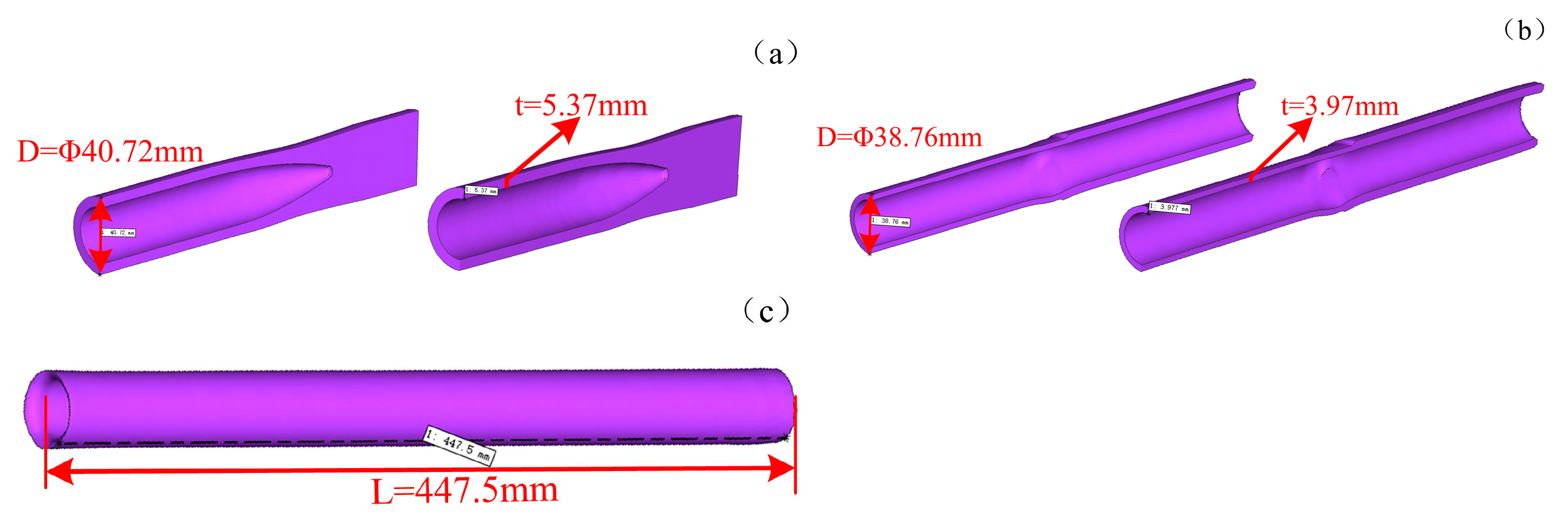
2.3.1. Macroscopic Size Analysis

In the actual rolling process, it is impossible to determine the outer diameter and wall thickness of the tube after piercing, so these can be established using the finite-element method. In Figure 6, the outer diameter D of the tube after separate piercing is approximately φ40.7 mm, and the wall thickness is approximately 5.37 mm. Once the tube has passed through the tube rolling area, diameter reduction and wall reduction are achieved. The outer diameter is approximately φ38.76 mm and the wall thickness is approximately 3.97 mm. A bar with a length of 150 mm is rolled into a tube with a length of 447.5 mm and the axial direction achieved is an extension of 2.98 times, which proved that the deformation effect of the TSR process is excellent.

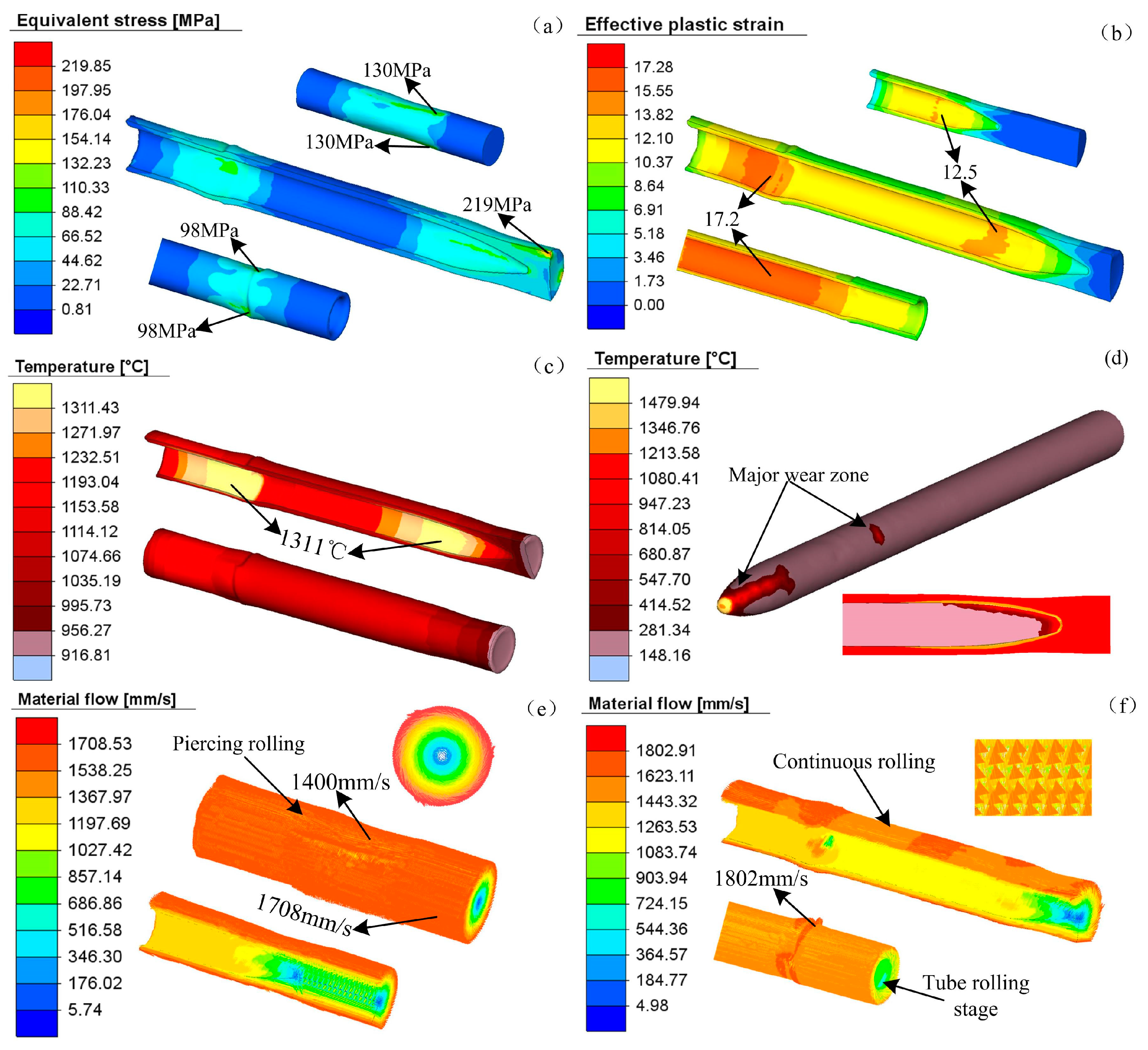
2.3.2. Stress-Strain Field, Temperature Field and Velocity Field Analysis

A stress peak appears on the outer surface of the bar in contact with the rollers during the TRS process, as shown in Figure 7a. When a single piercing is stabilized, the external surface stress of the material is maintained at 130 MPa. When the rolling tube is stabilized, the stress value of the titanium alloy tube is maintained at approximately 98 MPa. The maximum stress (219 MPa) in the figure is due to the restriction of the material flow at the end of the bar [16]. As shown in Figure 7b, the strain increased gradually during the whole process. The strain law of the TSR process can be summarized as follows: the strain on the inner surface of the tube is larger than that on the outer surface; the strain on the rolled part of the tube is larger than that on the piercing part.
The tube without a large temperature drop after piercing immediately enters the rolling stage. Figure 7c shows that the high-temperature area of the tube during the TSR process is mainly concentrated in the rolling strip of the piercing and rolling tubes. Although the outer surface of the tube also generates frictional heat, the temperature rise is relatively low due to the heat exchange with the rollers. The plug and rolling areas of the mandrel are the most severely worn, so it is necessary to pay attention to the cooling of the plug and the mandrel material selection in actual production.
In the process of piercing (Figure 7e), the velocity on the outer surface of the tube is large and the velocity at the center is small. The material flow within the compression zone (approximately 1400 mm/s) is much smaller than that at the billet end heads’ speed (1700 mm/s). The arrow group in the upper-right corner of Figure 7f indicates that the material has both axial and tangential partial velocities during rolling and that the movement mode is a spiral motion. Upon entering the tube rolling area, the increase in the roller speed makes the flow velocity of the outer surface of the material increase, especially in the area directly in contact with the roller. The material flow velocity on the outer surface is approximately 1800 mm/s.

2.3.3. Tension Analysis

The tension in the TSR process plays an important role in changing the metal flow and improving the forming effect of the tube [17]. When piercing and rolling simultaneously, the metal between the two sets of rollers is subjected to a pulling force from the rolling rollers, which is called tension. The tension variation law can be obtained by inserting tracking particles. With the rolling process, the tension increases when the particles gradually approach the rolling compression zone, but the inner surface is slightly smaller than the outer surface. Once near but not yet completely in the rolling zone, the tension reaches its maximum at approximately 44 MPa for both the internal and external surfaces. Once the particle enters the rolling area, the tension immediately changes into the compressive stress from the rollers and the value decreases rapidly. The variation trend of tension is shown in Figure 8.

3. Experiment and Heat Treatment

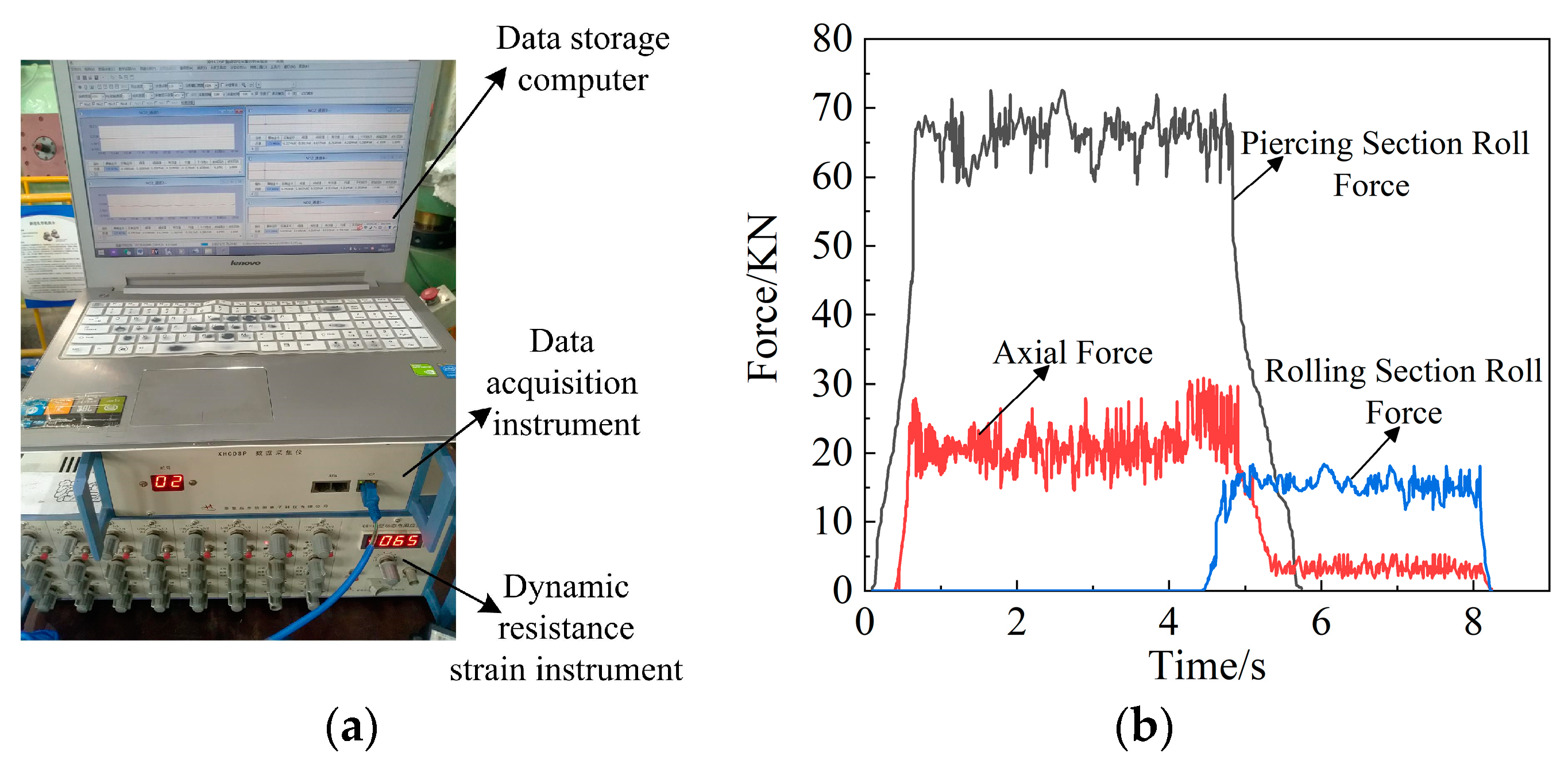
3.1. Introduction of Experimental Equipment

The rolling experiment was carried out on a three-roller TSR mill developed by our team as shown in Figure 9. In order to increase the contact area between the rollers and the bar, the rollers in the piercing part were removed and replaced with rollers that were φ190 mm larger (the original diameter was φ180 mm). The results of the experiment prove that this measure significantly improved the success rate.
For the main unit, the roller gap is adjusted by driving the roller to move with 12 holding-down bolts, the plug advance is adjusted by the position of the ejector trolley car, the feed angle is adjusted by the rotary frame and the roller speed of the tube rolling part is controlled by the frequency converter [18]. The field experiment process parameters were consistent with the finite-element simulation results. In order to establish a continuous rolling relationship, the bar length was different from that of finite-element simulation and the specifications were φ40 mm × 350 mm.
In all the metallographic experiments carried out in this paper, the sample preparation sequence comprised rough grinding, fine grinding, rough polishing, fine polishing and corrosion. An aqueous solution of hydrofluoric acid and nitric acid was used for corrosion [19]. Microstructure images were observed and preserved with a Leica DM2700M metallographic microscope(Leica, Wetzlar, Germany) and Zeiss Sigma 300 System scanning electron microscope(Zeiss, Oberkochen, Germany). Different positions of the samples were observed, and it was found that the microstructure type and grain size were consistent and that there was no gradient change.

3.2. Analysis of the Rolling Process and Rolled Tubes

3.2.1. Rolling Force Detection

The rolling force is detected by a sensor installed under the roller. As shown in Figure 10, in a stable state, the rolling force at the piercing stage (average is approximately 68 KN) is significantly greater than the rolling force at the rolling stage (17 KN), because the deformation tasks undertaken by the two processes are different. Piercing is the process of molding solid bars into hollow tubes with severe deformation. In the tube rolling stage, the hollow tubes are mainly reduced in diameter and wall thickness, and the deformation is relatively small. The axial force of the TSR process is divided into three stages. The first stage is only the working stage of the piercing roller and the plug, then the axial force is only the force on the plug. The second stage is the stage of simultaneous piercing and rolling and the axial component of friction between the mandrel and tube is added to the axial force. This is the reason why the axial force curve rises at the end of the piercing.
The third stage is the tube rolling after piercing. At this time, the axial force is only the friction component between the mandrel and the tube, which is approximately 2–3 KN. When the rolling is completed, the axial force returns to zero.

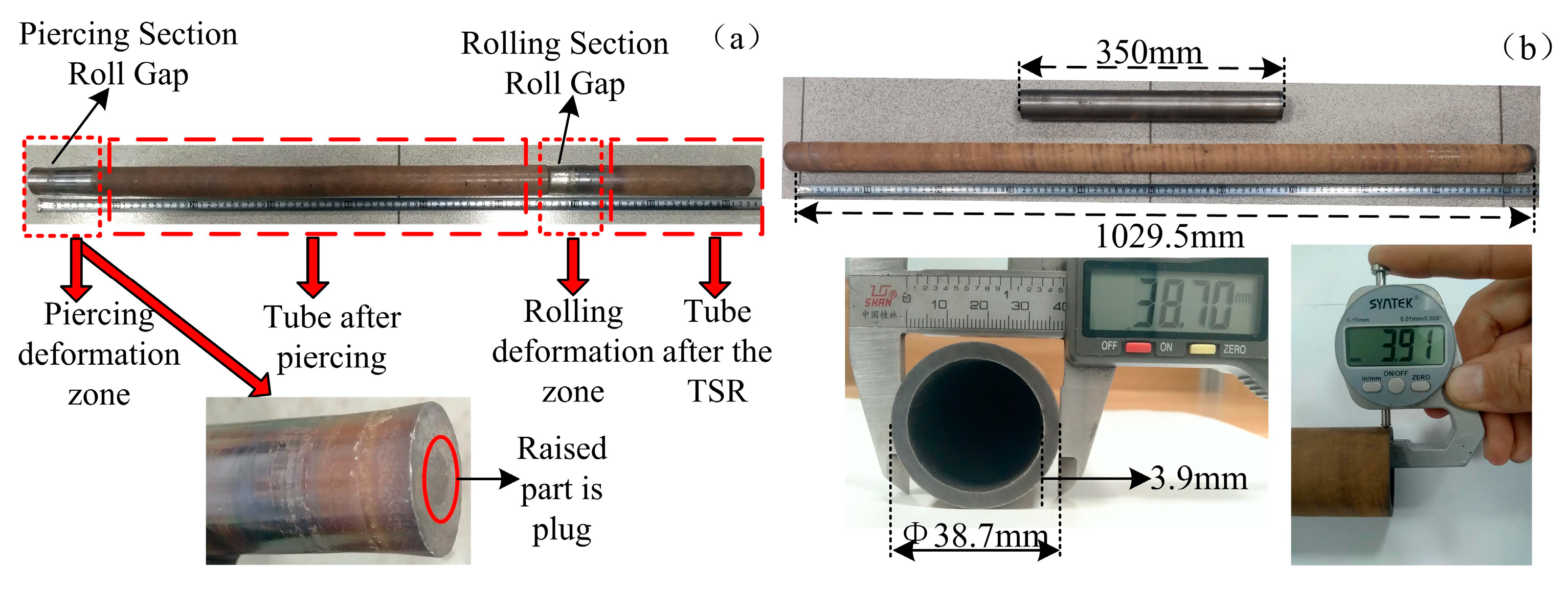
3.2.2. Macroscopic Size Analysis

In order to show the deformation effect of the TSR process, artificial shutdown and normal rolling were carried out in this study. A tube with obvious characteristics from the TSR process and a tube after smooth rolling were obtained, as shown in Figure 11. Following shutdown, the tube is divided into a piercing rolling zone, a tube after piercing, a tube rolling zone and a tube after rolling from left to right along the axial direction. The bright color of the metal in the rolled strip is caused by the friction between the roller and the material during the shutdown. In Figure 11a, the plug is still wrapped by the bar, but the end surface of the bar has formed a bulge, indicating that the plug will soon break through the material to achieve piercing. The material in the deformation area is obviously compressed and deformed.
The seamless titanium alloy tube rolled using the TSR process is shown in Figure 11b. The length of the titanium alloy tube after rolling was 1029.5 mm and the axial extension was 2.94 times. The outer diameter was approximately 38.7 mm and the wall thickness was approximately 3.9 mm. It can be seen from the end face that the seamless tube has a uniform wall thickness and good roundness. The finite-element simulation was completed in an ideal environment, while the field rolling experiment included many uncontrollable factors. Moreover, the center hole was premachined in the center of the bar, resulting in a certain amount of material loss, so the elongation was not completely consistent with the simulation, but it was relatively close.

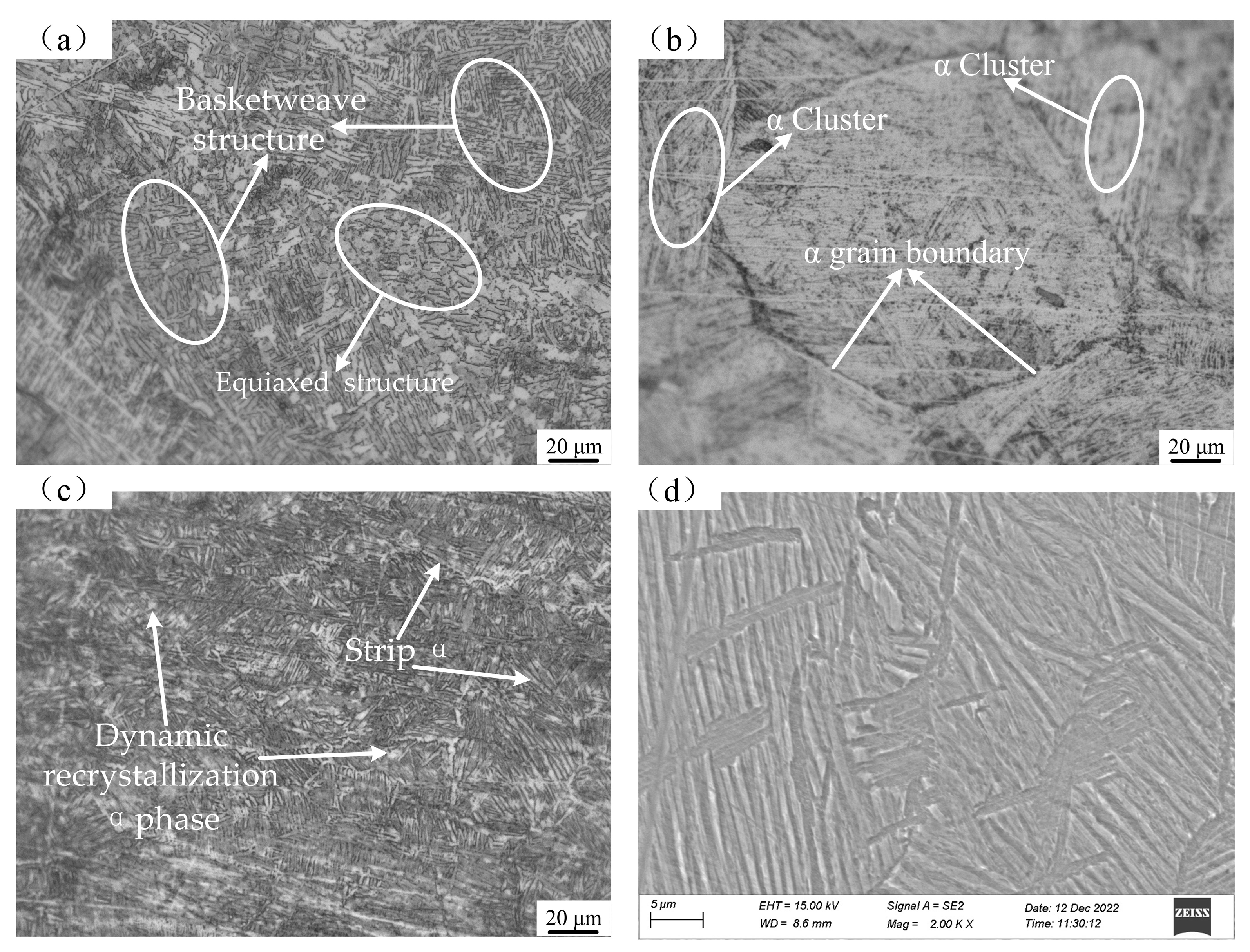
3.2.3. Microstructure Analysis

In order to accurately highlight the advantages of the TSR process, the microstructure of the tube after three-roller cross-piercing and TSR was analyzed, as shown in Figure 12. The original titanium alloy bar presents equiaxed and basketweave microstructure states, which are transformed into the high-temperature β phase after being heated at a temperature exceeding the phase transition point. Three-roller cross-piercing can refine the coarse high-temperature β phase. The deformed Widmanstatten structure formed after cooling is composed of elongated and straight α-phase clusters, β-transformed grains and continuous α-grain boundaries. For the TSR process, the high-temperature tube, which has completed the first refinement of the β grain in the piercing section, enters the rolling section immediately for secondary grain crushing. Therefore, the TSR process produces tubes with relatively fine β-grains at a high temperature, and the microstructure after cooling is completely different from the deformed Widmanstatten structure after piercing. The grain boundaries are destroyed to varying degrees, and the α grains become shorter and have complex orientations, forming a crisscross basketweave structure. The average size of the secondary strip-α phase is approximately 10~15 μm.
At the same time, there are certain equiaxed and blocky α grains, which show that the TSR process is accompanied by dynamic recrystallization. The average diameter of these randomly distributed, equiaxed α grains is approximately 5~8 μm. The seamless titanium alloy tube with a basketweave structure not only has good plasticity and impact toughness but also excellent high-temperature tensile strength, rupture strength and creep strength [20]. The microstructure evolution of the TSR process can be summarized as shown in Figure 13.

3.3. Research on Heat Treatment of TC4ELI Tube

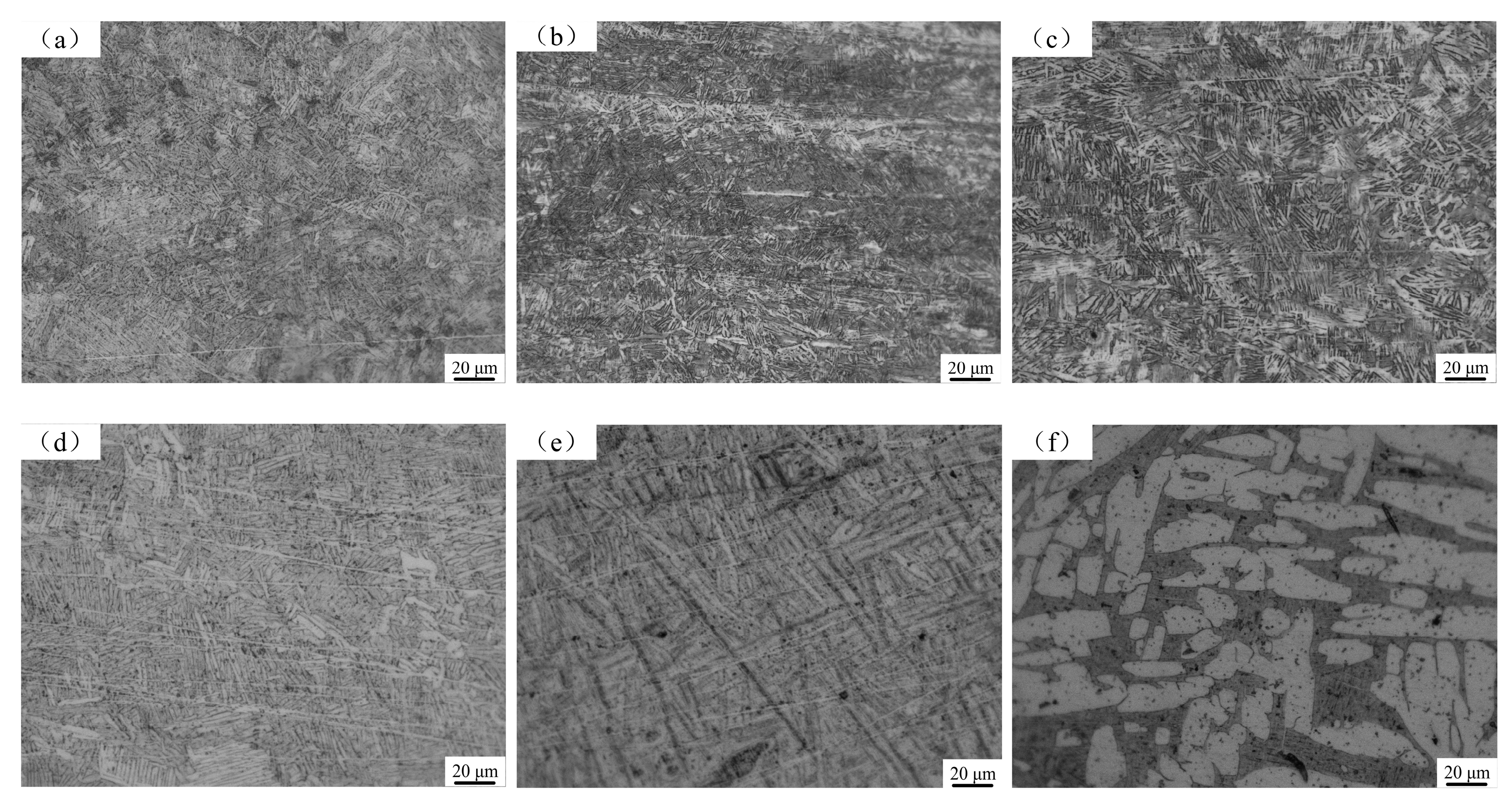
3.3.1. Effect of the Annealing Temperature on the Microstructure

Annealing treatment can eliminate stress, improve plasticity and stabilize microstructure. In order to study the effect of the annealing temperature on the microstructure of seamless titanium alloy tubes, we conducted annealing process research in a box-type resistance furnace, with heating temperatures of 700 °C, 750 °C, 800 °C, 850 °C, 900 °C and 950 °C and air cooling after holding the temperature for 1 h. The microstructure is shown in Figure 14.
Compared with the rolling state, the microstructure of the tube did not change significantly when the annealing temperature was 700 °C and 750 °C. When the annealing temperature was 800 °C and 850 °C, the thin strip α-phase grew during the annealing process and the cluster became slightly coarser, showing a basketweave structure. When the annealing temperature rose to 900 °C, the structure of the tube gradually became clear and uniform, the α-phase coarsened in both length and width and the structure still showed a typical basketweave structure. Following the temperature increase to 950 °C, a large number of strips and lamellar α-phases transformed into short rod α-phases, then collided with each other and were cut off. The short rod α-phase is approximately 40–60 μm in length and 10–20 μm in width. Therefore, α phases with small aspect ratios appeared and the equiaxed degree was intensified.

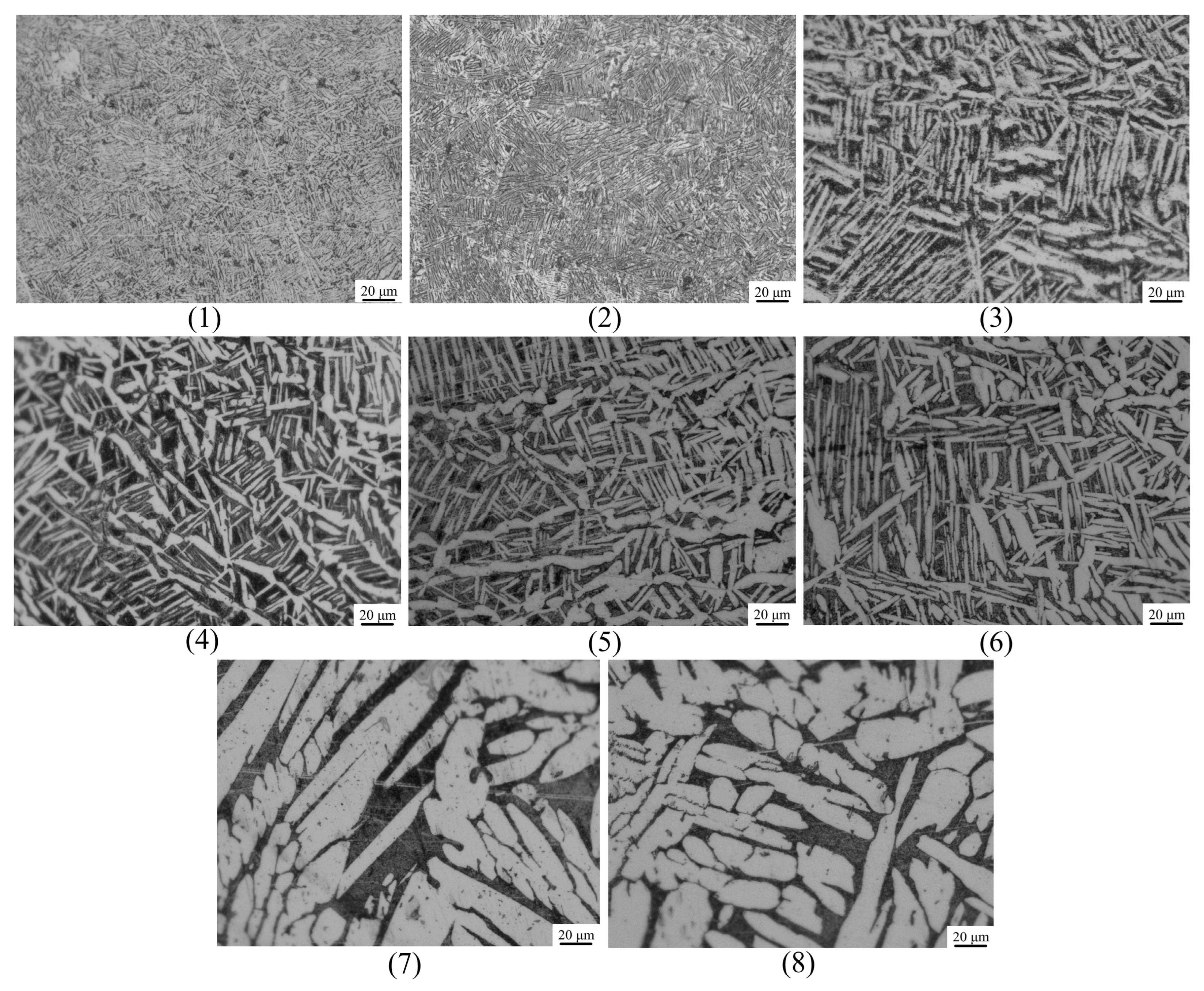
3.3.2. Effect of Solution-Aging on the Microstructure

Solution-aging treatments are the main heat treatment methods for strengthening titanium alloys. The medium-temperature solid-solution range is approximately 650–800 °C and the high-temperature solid-solution range is generally 40–100 °C below the phase-transition temperature. Most of the TC4 (including TC4ELI) phase-transition points are in the range 970–990 °C. In order to make this heat treatment universally instructive, the high-temperature solid-solution temperature was selected at 870–950 °C. Therefore, the solid-solution temperature of this scheme was selected successively from 650 °C, 780 °C, 910 °C (interval 130 °C) and 950 °C. The aging temperature range of TC4 titanium alloy is generally 520–550 °C, while researchers usually extend the aging temperature to 450–600 °C, so the aging temperatures of 465 °C, 525 °C and 585 °C (interval 60 °C) were selected in this scheme. The specific scheme is shown in Table 3. WC means water cooling, and AC means air cooling.
The corresponding microstructure of a seamless TC4ELI tube after the heat treatment of each scheme in the table is shown in Figure 15, and (1)–(7) indicates the scheme number.
The cooling method was water-cooled in order to retain the high-temperature supersaturated solid solution, which was generated by the dissolution of the unstable α-phase. Compared with schemes (1), (2), (4) and (7) in Figure 15, the aging temperature remains constant, and the grain size increases with the rise in the solid solution temperature. The secondary α phase in the shape of needles or thin strips becomes more directional and the equiaxed degree also increases. The microstructure also becomes obvious and is easier to observe when the solid solution temperature reaches 910 °C. When the solid solution temperature reaches 950 °C, the strip-shaped α-phase is replaced by a large number of massive α-grains. Comparing (3), (4) and (6) in Figure 15, it can be seen that the solid solution temperature remains constant and the strip-shaped α grains in the figure also coarsen to a certain extent with the increase in the aging temperature. However, the degree is relatively light, indicating that the aging treatment has little effect on the microstructure in this process. The comparison between (7) and (8) also confirms this rule. Comparing (4) and (5) in Figure 15, it is found that when the solution-aging temperature is the same but the aging time is different, the metallographic structure of the two groups is almost similar, which indicates that the aging time has less influence on the microstructure. Microstructure evolution has proven that solution-aging treatment can effectively promote the dissolution and transformation between phases in the TC4ELI matrix.

3.3.3. Hardness Change after the Heat Treatment

The hardness of a metal can represent its ability to resist deformation; it is also a comprehensive index that characterizes the mechanical properties of the material, such as elasticity, plasticity, toughness and strength. The seamless titanium alloy tube in this study is used in the field of oil and gas. Following the heat treatment, the seamless titanium alloy tube was sampled and tested according to the national standard “SYT 6896.3-2016”. The hardness test was completed by the HR-150A Rockwell hardness tester(Decca, Shenzhen, China). Each sample was tested at several points. The distribution of the average hardness is shown in Figure 16.
The average Rockwell hardness of the rolled seamless tubes without heat treatment is 30.8 HRC. It can be seen from Figure 16a that following the high-temperature annealing (900 °C, 950 °C), the hardness value exhibits a certain increase, but when the annealing temperature is in the range 700–850 °C, the fluctuation in the hardness is small. Figure 16b shows that the solution-aging process scheme adopted in this study has improved the hardness to varying degrees; in particular, the average hardness values of tubes after the heat treatment in scheme (3) and scheme (7) reached 40.7 HRC and 41.6 HRC, respectively, which is of great significance for strengthening the TC4ELI tube. Therefore, it can be concluded that the transformation of the β phase into martensite produced by the high-temperature heat treatment is more conducive to improving the hardness level of seamless titanium alloy tubes produced using the TSR process, and the solution-aging process is more suitable than the annealing process.

4. Conclusions

(1)
The optimal parameters for the production of seamless titanium alloy tubes using the TSR process were selected using the finite-element method. The simulation results and field experiments showed that the proposed parameters could produce titanium alloy tubes smoothly.
(2)
The seamless titanium alloy tubes prepared using the TSR mill have a uniform wall thickness and achieve a 2.94-times axial extension. The microstructure is completely different from the deformed Widmanstatten microstructure, showing a basketweave structure composed of a uniform and dense strip-like α phase and β transformation phase.
(3)
The seamless TC4ELI tubes after heating-preservation-cooling using different heat-treatment systems all present a basketweave structure, but the grain size is different. Combined with the hardness test, it can be seen that the 950 °C annealing and the 950 °C solid solution-525 °C aging scheme have important significance for improving the hardness of seamless titanium alloy tubes produced using the TSR process.

Author Contributions

All the authors contributed to this paper. C.C. and J.C. conceived and designed the experimental scheme, Y.S. provided theoretical guidance, C.L. completed the simulation, and C.C. processed the experimental data and wrote the manuscript. All authors have read and agreed to the published version of the manuscript.

Funding

The authors acknowledge the funds from the Science and Technology Key Development Project of Shanxi Province, China (201903D121049) and the Major Project of Ministry of Science and Technology of Shanxi Province, China (No. 20191102009).

Institutional Review Board Statement

Not applicable.

Informed Consent Statement

Not applicable.

Data Availability Statement

Not applicable.

Conflicts of Interest

The authors declare that there is no relevant conflict of interest.

References

  1. Guo, L.; He, W.X.; Zhou, P.; Liu, B. Research Status and Development Prospect of Titanium and Titanium Alloy Products in China. Hot Work. Technol. 2020, 49, 22–28. [Google Scholar]
  2. Zhang, W.G.; Li, Y.Y.; Wang, P.; Yan, W.J.; Dong, X.F. Analysis for the development of titanium alloy casting industry in China. World Nonferr Met. 2019, 21, 199–200. [Google Scholar]
  3. Zhang, D.W.; Zhao, S.D.; Zhu, C.C.; Zhang, J.; Hu, Y.H.; Duan, L.H. Finite Element Analysis of Piercing Process of Piercing Extrusion for Titanium Alloy Solid Ingots. Rare Metal Mater. Eng. 2016, 45, 86–91. [Google Scholar]
  4. Ou Yang, D.L.; Cui, X.; Lu, S.Q.; Zhu, H.A.; Du, H.M. Effect of spinning parameters on texture of TC21 titanium alloy cylindrical during spinning. Trans. Mater. Heat Treat. 2021, 42, 143–151. [Google Scholar]
  5. Liu, W.; Zhang, Y.B.; Hou, Z.J. Research Status of Ti and Ti Alloy Pipe Rolling Technology. Metal World 2019, 6, 5–7. [Google Scholar]
  6. Wang, C.F.; Xue, J.G.; Zhou, Z.Y.; Ji, B.; Wu, Y.Y.; Zhang, C.X.; Sun, H.M. A preliminary Discussion on Making Ti-alloy OCTG by Using the Floating-Mandril Method. Nonferr Min. Metal. 2015, 31, 34–36. [Google Scholar]
  7. Wang, H.; He, F.M.; Hu, S.Z.; Guo, H.; Zheng, B.; Chen, Y. Research and Development of Φ610 mm TC4 Big Diameter Titanium Alloy Hot Rolled Seamless Tube. Steel Pipe 2019, 48, 25–30. [Google Scholar]
  8. Zhang, B.; Sun, Y.; Zhao, S.J.; Liu, J.B.; Yang, Y.C. Titanium Seamless Pipe Rolling Design and Experimental Study. In Proceedings of the 11th China Iron and Steel Annual Conference—S03, Beijing, China, 21–22 November 2017; pp. 854–858. [Google Scholar]
  9. Yang, Q.; Hui, S.X.; Ye, W.J.; Xu, Z.; Dai, C.; Lin, Y. Effect of ‘Q’ Ratio on Texture Evolution of Ti-3Al-2.5V Alloy Tube during Rolling. Materials 2022, 15, 817. [Google Scholar] [CrossRef] [PubMed]
  10. Bayona-Carrillo, N.; Bozzolo, N.; Fundenberger, J.J.; Thomas, B.; Camelin, P.; Lenarduzzi, E.; Wagner, F. Effect of Recrystallization on Tensile Behavior, Texture, and Anisotropy of Ti-3Al-2.5 V Cold Pilgered Tubes. Advan. Eng. Mater. 2011, 13, 383–387. [Google Scholar] [CrossRef]
  11. Zhang, F.P. The Research on the Production and High Temperature Properties for the TA22 φ8 mm × 1 mm Titanium Alloy Tube. Master’s Thesis, Xi’an University of Architecture and Technology, Xi’an, China, 2019. [Google Scholar]
  12. Mao, F.; Wang, F.; Shuang, Y.; Hu, J.H.; Chen, J.X. Deformation Behavior and Experiments on a Light Alloy Seamless Tube via a Tandem Skew Rolling Process. Metals 2020, 10, 59. [Google Scholar] [CrossRef] [Green Version]
  13. Mao, F.L.; Shuang, Y.H.; Wang, Q.H.; Wang, F.J. Effect of process parameters on rolling force and dimensional precision of tubes rolled by tandem skew rolling process. J. Plast. Eng. 2018, 25, 108–114. [Google Scholar]
  14. Pater, Z.; Tomczak, J.; Bulzak, T.; Wojcik, Ł.; Skripalenko, M.M. Prediction of ductile fracture in skew rolling processes. J. Mach. Tools Manuf. 2021, 163, 103706. [Google Scholar] [CrossRef]
  15. Ding, X.F.; Shuang, Y.H.; Shi, Y.P. Study on Process Parameters of Skew Rolling Piercing of Magnesium Alloy. Hot Work. Technol. 2017, 46, 146–149. [Google Scholar]
  16. Wang, F.J.; Mao, F.L.; Shuang, Y.H.; Chen, J.X.; Hu, J.H.; Wang, Q.H. Kinematic analysis and experiment research on tandem skew rolling process for tube. Forg. Stamp. Technol. 2021, 46, 215–222. [Google Scholar]
  17. Babajamali, Z.; Aghadavoudi, F.; Farhatnia, F. Pareto multi-objective optimization of tandem cold rolling settings for reductions and inter stand tensions using NSGA-II. ISA Trans. 2022, 130, 399–408. [Google Scholar] [CrossRef] [PubMed]
  18. Chen, J.X.; Mao, F.L.; Shuang, Y.H.; Wang, F.J.; Wang, Q.H.; Chen, C. Finite element simulation and experiment study on tandem skew rolling process of tube. For. Stamp. Technol. 2019, 44, 101–108. [Google Scholar]
  19. Huang, D.M.; Tang, J.; Yang, X.M. Preparation Methods of Metallographic Samples of Different Types of Titanium and Titanium Alloys. Ph Test. Chem. Anal. 2021, 57, 34–39. [Google Scholar]
  20. Yadav., P.; Saxena, K.K. Effect of heat-treatment on microstructure and mechanical properties of Ti alloys: An overview. Mater. Today Proceed. 2020, 26, 2546–2557. [Google Scholar] [CrossRef]
Figure 1. Diagram of the TSR process.
Metals 13 00527 g001
Figure 2. Simulation model of the TSR process.
Metals 13 00527 g002
Figure 3. Flow curves of TC4ELI at different temperatures: (a) 950 °C; (b) 1000 °C and (c) 1050 °C.
Metals 13 00527 g003
Figure 4. Influence of key parameters on piercing: (a) the roller gap; (b) the plug advance.
Metals 13 00527 g004
Figure 5. Influence of the roller speed on the tube after the TSR process: (a) wall thickness; (b) elongation.
Metals 13 00527 g005
Figure 6. Different stage dimensions: (a) tube after piercing; (b) tube after rolling and (c) total length after the TSR process.
Metals 13 00527 g006
Figure 7. Various deformation laws in the TSR process: (a) stress filed; (b) strain field; (c) temperature field of the tube; (d) temperature field of the plug and mandrel; (e) velocity field during piercing and (f) velocity field during rolling.
Metals 13 00527 g007
Figure 8. Tension variations in the TSR process.
Metals 13 00527 g008
Figure 9. Field experiment: (a) the TSR mill; (b) the experiment process.
Metals 13 00527 g009
Figure 10. Rolling force detection: (a) rolling force acquisition system; (b) rolling force curve.
Metals 13 00527 g010
Figure 11. Seamless tube appearance: (a) artificial shutdown; (b) tube after the TSR process.
Metals 13 00527 g011
Figure 12. Metallographic microstructure: (a) TC4ELI bar, (b) tube after piercing and (c,d) tube after the TSR process.
Metals 13 00527 g012
Figure 13. Microstructure evolution in TSR process.
Metals 13 00527 g013
Figure 14. Microstructure after different annealing temperatures: (a) 700 °C; (b) 750 °C; (c) 800 °C (d) 850 °C; (e) 900 °C and (f) 950 °C.
Metals 13 00527 g014
Figure 15. Microstructure after different solution-aging schemes. (1)–(8) indicates the scheme number.
Metals 13 00527 g015
Figure 16. Hardness comparison after the heat treatment: (a) annealing; (b) solution-aging.
Metals 13 00527 g016
Table 1. Range of parameters in the TSR process.
ItemPiercing SectionRolling Section
parameterFeed angle
/deg
Plug
advance
/mm
Roller
gap
/mm
Roller
speed
/rpm
Feed angle
/deg
Entrance face angle
/deg
Roller
gap
/mm
Roller speed
/rpm
Range of Parameters7–815–2534–371698–10437–39<200
Table 2. Element composition of TC4ELI bar.
SpecimenElement %
FeCNONiAlMoV
TC4ELI0.2070.0060.0190.12-6.26-4.27
Table 3. Solution-aging treatment scheme for the tube after the TSR process.
SchemeSolution Temperature/°CSolution Time/hCooling ModeAging Temperature/°CAging Time/hCooling Mode
(1)6501WC5254AC
(2)7801WC5254AC
(3)9101WC4654AC
(4)9101WC5254AC
(5)9101WC5258AC
(6)9101WC5854AC
(7)9501WC5254AC
(8)9501WC5854AC
Disclaimer/Publisher’s Note: The statements, opinions and data contained in all publications are solely those of the individual author(s) and contributor(s) and not of MDPI and/or the editor(s). MDPI and/or the editor(s) disclaim responsibility for any injury to people or property resulting from any ideas, methods, instructions or products referred to in the content.

