Abstract
In the present study, a dry sliding wear test has been conducted to analyse the wear rate of Ti-6Al-4V alloy specimens which were fabricated using selective laser melting and conventional methods. Microstructure, micro- and nanohardness, and wear behaviour of selective laser melting specimens were investigated and compared with commercially available conventionally fabricated Ti-6Al-4V specimens. The mechanism correlating microstructure and wear behaviour of conventional and selective laser melting based Ti-6Al-4V specimens have been explained. The microhardness of the selective laser melting specimen was improved by around 22.4% over the specimen from the conventional method. The selective laser melting specimen showed broadened peaks and an increase in intensity height greater than that of the conventional specimen due to the presence of the martensite phase. The selective laser melting specimen possessed 41.4% higher nanohardness than that of the conventional specimen. The selective laser melting specimen had a 62.1% lower wear rate when compared to that of the conventional specimen. The selective laser melting specimen exhibited 62.7% less coefficient of friction than that of the conventional specimen at a 50 N load with 1.2 m/s sliding velocities. The finer needle-like microstructures of the specimen produced using the selective laser melting process had higher wear resistance, as it had higher hardness than the conventional specimen.
1. Introduction
Ti-6Al-4V alloy has drawn the attention of many researchers due to its high specific strength, corrosion resistance, good biocompatibility, etc., and has application in aerospace, automobile, and biomedical industries [1]. Niu et al. [2] performed sliding wear tests in different environments such as dry and water. It was found that the Ti-6Al-4V alloy surface was affected due to abrasion and adhesion wear. Dong [3] studied the wear behaviour of Ti-6Al-4V alloy and found that it has low abrasive wear resistance due to its high-plasticity property. Attempts to improve the microstructure, mechanical, and tribological properties of a material are the primary aim of researchers to enhance the service life of the component. Microstructural modification is one way to enhance the property of Ti-6Al-4V alloys, which can be achieved using different fabrication methods.
Recently, components have been fabricated based on the additive manufacturing (AM) method which has the capability to produce the small-size complex geometry needed by different industries. Selective laser melting (SLM) is one of the effective additive manufacturing methods used to melt the loose powder layer to create solid layer material. It eliminates the wastage of material and saves energy compared to other manufacturing processes [4]. SLM techniques were commonly used to print the Ti-6Al-4V-alloy-based component for the above-mentioned industries. Bartolomeu et al. [5] fabricated Ti-6Al-4V alloy by using the laser powder bed fusion method and carried out the ball-on-disc wear test. The microhardness of laser powder bed fusion based specimen and the conventionally processed sample were measured as 390 HV and 340 HV, respectively. It was stated that the wear rate of the laser powder bed fusion based specimen had a lower value than that of the conventionally processed sample, which confirmed that the test specimen followed Archard’s law. In addition, some contradicting results were also observed in the open literature. Zhen Xu et al. [6] experimentally found that Inconel-718 exhibited higher creep strength when it was fabricated through the forging process (63.9 h) than that of the selective laser melting process (24.4 h) due to the presence of continuous δ-phases at the grain boundary region and high residual stress accommodated in the SLM Inconel 718 specimen. In addition, Nadin Al-Haj Husain [7] fabricated the polymers by additive manufacturing as well as conventional methods and studied the microhardness. Based on the experimentation, it was found that the additive-manufactured polymers possess lower microhardness than that of the conventional specimen. Based on the above analysis, it is revealed that SLM products do not always exhibit superior properties to the conventional manufacturing process. Moreover, Palanisamy et al. [8] stated a contradicting result that the wear rate of laser powder bed fusion based specimens is not dependent on their hardness. This reveals that the wear properties of Ti-6Al-4V alloys have been extensively studied, and different conclusions have been drawn. Moreover, the wear behaviour of SLM-based Ti-6Al-4V specimens has not been studied extensively. Hence, in the present study, microstructure, micro- and nanohardness, and wear behaviour of SLM-based Ti-6Al-4V specimens have been investigated and compared to commercially available conventionally fabricated (CACF) Ti-6Al-4V specimens. The mechanism correlating microstructure and wear behaviour of CACF and SLM-based Ti-6Al-4V specimens are explained.
2. Materials and Methods
2.1. SLM Process
Ti-6Al-4V powder with a particle size of 15 to 53 µm was purchased from Circle metal powder company, Taiwan. SLM-based additively manufactured Ti-6Al-4V specimens were made using an SLM machine (M280, Germany). The process parameters which are listed in Table 1 were used to fabricate the Ti-6Al-4V specimens for obtaining nearly fully dense products. The Ti-6Al-4V loose powder was initially levelled as a thin layer across the base plate to form the powder bed. A fibre laser was used to melt this powder bed and scanned line by line to form consolidated layers. After this layer was formed, new Ti-6Al-4V loose powders were deposited on the top of the current layer and melted. This principle was repeated to form multiple additive layers, and thereby the SLM-based Ti-6Al-4V specimens were created. The fabrication process was performed in an argon shroud gas atmosphere.

Table 1.
SLM process parameter.
2.2. Wear Study
Wear tests were performed on the pin-on-disc wear test machine (TR-20LE-PHM 400-CHM 500, Ducom Instruments, Karnataka, India). Both CACF and SLM specimens were made into 30 mm × 30 mm × 6 mm sizes to perfectly fit in the specimen pin holder for pin-on-disc wear tests. CACF and SLM specimens were used as pins, whereas hardening steel with dimensions of 100 mm in diameter and 10 mm thickness was used as the disc. The wear tests were run at 50 N load and a sliding velocity of 1.2 m/s with 2800 m sliding distance under the atmospheric air condition. Resultant graphs of the wear test contained wear depth against sliding time and frictional force against sliding time which were recorded automatically by the controller of the pin-on-disc tribometer. Wear rate against a sliding time graph and the coefficient of friction (COF) against a sliding time graph were plotted by using Equations (1) and (2), respectively.
2.3. Characterization
All specimens were polished by SiC abrasive grinding papers up to grit 2400 to achieve an average surface roughness (Ra) of 0.5 μm. The surface roughness of the specimens was measured by using a white light interferometer (Rtech instruments, San Jose, CA, USA). The presence of phases of gas-atomized Ti-6Al-4V powder, CACF, and SLM specimens were evaluated using an X-ray diffraction (XRD) tester (D/MAX/2200/PC Ultima IV, Regaku, Akishima, Japan). The CACF and SLM specimens were polished and etched with a solution that contained a mixture of 5 mL nitric acid, 85 mL water, and 10 mL hydrofluoric acid. The microstructure was analysed with Field emission scanning electron microscopy (FESEM) (Sigma Gemini Column, Carl Zeiss, Dublin, CA, USA). Microhardness tests were conducted on these polished samples using 402 MVD Vicker’s microhardness (Wolpert Wilson Instruments, Campbellford, ON, USA) at 100 g load with a 30 s dwell time. A nanoindentation test (TI980 Hysitron, Bruker Nano indenters, Santa Barbara, CA, USA) was carried out to study the nanohardness of the CACF and SLM specimens at an applied load of 2000 μN.
3. Results
3.1. XRD Analysis
The XRD plot of the gas-atomized powder, CACF Ti-6Al-4V specimen, and SLM Ti-6Al-4V specimen is shown in Figure 1. The XRD graph reveals that both the powder and the specimens possessed hexagonal close-packed (HCP) and body-centred cubic (BCC) structures. It indicates that the SLM specimen exhibited texture in the (002) plane. The height and broadening of peaks of CACF and SLM specimens varied in most of the peaks. The presence of α-phase Ti in powder and specimens was visible in the HCP structure. Asymmetric broadening of peaks was observed on both the specimens at the diffraction angles between 38° and 40°. Moreover, the SLM specimen had more broadening as well as a larger peak height than that of the CACF specimen at the diffraction angles between 38°, 40°, and 71° due to the presence of the martensite phase [9]. The broadening width of α-Ti phase at the 39° diffraction angle occurred up to 0.4° compared to the CACF specimen [10]. The CACF specimen had peaks with a slight deviation from the SLM specimen at a diffraction angle of 39°. XRD investigations revealed that the SLM specimen possessed a dominant α-Ti phase compared to the CACF and gas-atomized powder at 39°. The relative intensity was higher than that of other specimens, which confirmed strong texture formation. Corresponding texture formed at 39° in the plane of (002) was the strongest among all the phases. Moreover, the SLM specimen had grains with a high aspect ratio as it had elongated grains with little thickness. The new peak formation and increment in diffraction peak intensity confirmed the phase transformation of the SLM specimen.
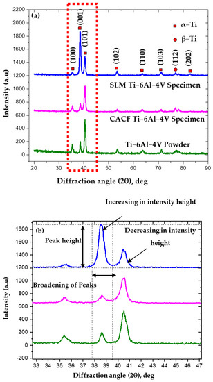
Figure 1.
(a) XRD pattern of gas-atomized powder, CACF specimen, and SLM specimen, and (b) magnified view of (a).
The α-Ti phase peaks indicate that the texture was grown along the plane direction of (101). A few of the β-phases were found in gas-atomized powder as well as both the specimens. The presence of β-phase in the SLM specimen occurred due to the occurrence of the thermal effect on the previously deposited layer while depositing the present layer during the SLM process. The volume fraction of the β-Ti phase in the SLM specimen did not exceed the value of 5%. It can be viewed from the XRD result of the SLM specimen that the content of the β-Ti phase was reduced compared to the CACF specimen at 79° due to the rapid cooling of the molten pool during the SLM process. In addition, the CACF specimen had a singular shape, and the SLM specimen had a fine acicular shape. These findings are in accordance with the reported work [11]. It revealed that the martensitic phase was formed in the SLM Ti-6Al-4V specimen. The high cooling rate was offered by the SLM process in the range 106 C/s [12]. No such cooling rates occurred during the CACF specimen that resulted in different microstructure formation between these specimens. The SLM specimen had lattice parameters of a = 0.2925 nm and c = 0.4667 nm, which are higher than the standard lattice value [9].
3.2. Microstructure and EDS Analysis
The microstructure of gas-atomized Ti-6Al-4V powder used in the SLM process is shown in Figure 2a. Non-porous spherical shape particles with particle size in the range of 40 to 50 μm were observed. These spherical shape particles were resultant from the high-velocity gasses that struck the molten metal. The microstructure of CACF and SLM specimens are shown in Figure 2b and Figure 3c, respectively. Both α- and β-phases of the Ti element are observed in Figure 2b. Equiaxed α-phase occupied most of the region of the CACF specimen. From the microstructure of the SLM specimen, a layered structure possessing elongated grains as well as equiaxed grains can be viewed in Figure 2c. Thermal damage and distortion of the adjacent layer are not seen in Figure 2c, as the SLM process allowed the material to deposit with the advantages of controlled heat input. In addition, the finer microstructure was obtained due to the rapid melting and cooling process. Moreover, spherical shaped Ti-6Al-4V powder increased the flowability of the molten pool, thereby giving rise to a defect-free geometrical structure and smooth final finish of the SLM specimen [13].
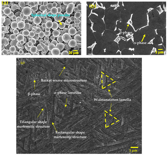
Figure 2.
FESEM micrograph of: (a) gas-atomized powder, (b) CACF structure with α- and β-phase, (c) SLM-produced structure with α-phase, β-phase, and martensite.
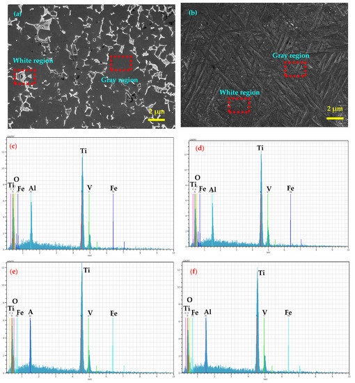
Figure 3.
Micrograph of EDS analysis: (a) CACF specimen, (b) SLM specimen, (c) grey region of CACF specimen, (d) white region of CACF specimen, (e) grey region of SLM specimen, (f) white region of SLM specimen.
The SLM specimen has Widmanstatten structures, martensitic rectangular structures, and β-phases as Ti-6Al-4V alloy was more sensitive to thermal input that led to creating temperature fields, resulting in the formation of complex microstructures during the SLM process. The Widmanstatten structures are observed in Figure 2c. The figure contains acicular α-phase lamellae with a grey contrast and a β-phase with a white contrast. Ti-6Al-4V alloy was deposited at a molten temperature of 1668 °C during the SLM process. As a result, the bottom layer experienced more heat than the beginning layer. Regions in the layer which experienced a temperature above 980 °C have a fine needle-like martensitic structure, as they transformed from β with the rapid cooling process. Regions which went below 980 °C have Widmanstatten structures formed from the transformed α- + β-phases [14]. Every Ti-6Al-4V layer of the SLM component continuously experienced thermal treatment while depositing the subsequent layer. Hence, this martensitic microstructure formed in some of the regions, within which the α-phase lamellar Widmanstatten structure developed. The presence of different grey shades of the acicular α-phase lamellae in Figure 2c is derived from the orientation contrast and not the material contrast. These acicular α-phase lamellae appeared in different forms such as irregular bundles and sets of triangular structures [15]. Moreover, it contained rectangular-structured martensitic grains which have the shape of very thin large needles. Some of the martensitic structures are visible in the form of smaller triangular structures. Between the thin large-sized needle-like martensitic structures, smaller-sized triangular structures were formed. The overall microstructure of the SLM specimen was viewed as a basket-weave microstructure [16].
EDS analysis was performed on the grey region α-phase lamellae and white region β-phase. The resultant graph of both the specimens is shown in Figure 3. Corresponding quantitative values are listed in Table 2. The result reveals that the α-phase region (grey region) of the CACF specimen (Figure 3c) has a Ti element at an atomic wt.% of 81.98. The presence of the Al element is around 10.21% atomic wt., which is slightly higher than the standard value, whereas the V elements are concentrated around 4.32% atomic wt. Moreover, around 2.46 and 1.03% Fe and C were present in the grey region, respectively. The β-grains were visible at the edges of the bundles of acicular α-phase lamellae boundaries [17]. The EDS result of the β-grain of the CACF specimen is shown in Figure 3d, which confirms the presence of Ti, Al, and V elements with atomic wt.% 82.61, 10.20, and 5.60, respectively. It shows that the V concentration value is higher than that in the grey region. Fe and C elements were present with the atomic wt.% of 1.03 and 0.56, respectively. Similarly, the atomic wt.% of Ti, Al, V, F, and C in the grey region (Figure 3e) of the SLM specimen were 86.82, 6.95, 3.67, 1.92, and 0.64, respectively, whereas the white region (Figure 3f) of the SLM specimen had 82.19, 7.25, 6.49, 2.21, and 1.86, respectively. It shows that the intensity of V is higher at the β-phase region, whereas the Al concentration is higher at the α-phase region.
Table 2.
EDS analysis results of CACF and SLM specimens.
The distribution of Ti, Al, V, and Fe elements in the CACF Ti-6Al-4V specimen and SLM Ti-6Al-4V specimen was examined using EDS mapping techniques. The resultant elemental mapping images are shown in Figure 4. The images confirm that Ti, Al, and V elements are present in both the specimens and distributed throughout the region. Mapping of elements was recorded at the same area, and it was found that the distribution of Ti elements was majorly segregated as a red colour (Figure 4a) in some regions of the CACF Ti-6Al-4V specimen, whereas uniformly distributed as a red colour (Figure 4b) throughout of the region of the SLM specimen. Similarly, other major elements such as Al and V followed the same trend as the Ti element. It reveals that the elemental distribution was better in the SLM specimen than the CACF specimen. Moreover, metallurgical bonding between the elements was better in the SLM specimen compared with the CACF specimen. Along with these major elements, some minor elements such as Fe, C, and O are observed in Figure 4 for both the specimens. Hence, the intensity of Ti, Al, and V elements was higher in the SLM specimen than the CACF specimen. The Fe element is very prone to segregation in the liquid phase and is deposited at the grain boundaries during the casting decrease in the formation of β-phases which may be the reason for the higher content of Fe in CACF and SLM specimens. Ling Ding et al. [18] experimentally found that the Fe elements segregated in the Ti-6Al-4V alloys at a rate six times greater compared to the nominal composition. Agnieszka Szkliniarz [19] found that the stabilization of phases, solubility, and interstitial-based solid solutions in the titanium alloy was the important reason for the variation of carbon in the Ti alloy specimen.
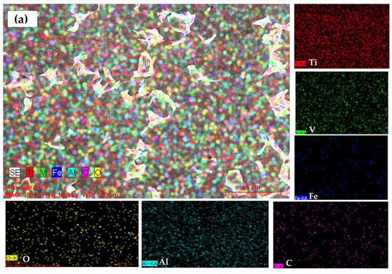
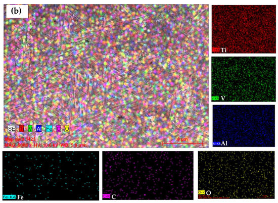
Figure 4.
Elemental mapping resultant images of: (a) CACF specimen and (b) SLM specimen.
3.3. Microindentation and Nanoindentation
Microhardness was measured in the CACF specimen as well as the SLM specimen, and the indentation impression mark of the microhardness tested surfaces are shown in Figure 5a,b. Microhardness values for the CACF specimen as well as the SLM specimen are shown in Figure 5c. The average microhardness of the CACF specimen and the SLM specimen are 380.7HV0.1 and 466.2HV0.1, respectively. It shows that the SLM specimen withstood the applied loads compared with the CACF specimen. The SLM specimen did not shear off (Figure 5b) during the microhardness test, whereas the CACF specimen sheared at both sides (Figure 5a). The difference in the microhardness of the SLM component with the CACF specimen suggested an influence from the manufacturing methods. The microhardness of SLM is higher than that of the values reported for both the wrought alloy (372 HV) and electron beam melting methods (EBM) (410 HV) [20]. The SLM build specimen possessed relatively consistent standard deviations of microhardness while the conventional specimen had larger deviation. Moreover, the microhardness values of the CACF specimen were highly fluctuated, whereas the variation of microhardness of the SLM specimen was lower, which is observed in Figure 5c. The size of the impression indentation area was greater in the CACF specimen (Figure 5a), whereas the impression indentation area in the SLM specimen (Figure 5b) was smaller. It shows that the hardness of the material was inversely proportional to the size of the grains. The sheared region was observed around the indentation impression region in the CACF specimen, and cracks were also propagated from the indentation edge to the surface region, whereas SLM specimens overcome these drawbacks at the same applied load and dwell time due to the formation of fine microstructures.
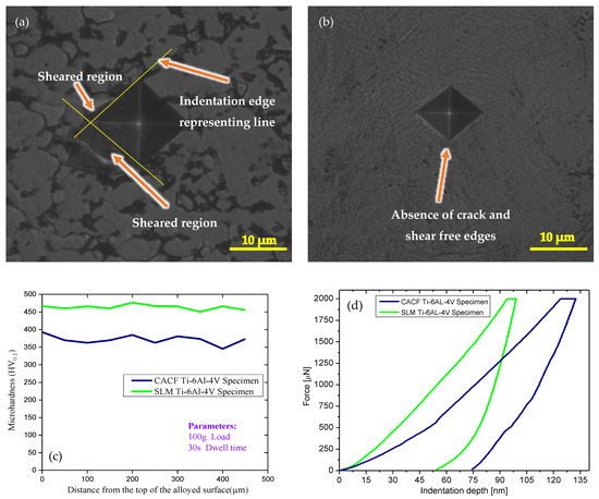
Figure 5.
(a,b) Microhardness indentation marks on CACF and SLM specimens, respectively. (c) Microhardness graph of CACF and SLM specimens. (d) Nanohardness profiles with their corresponding indent marks for CACF and SLM specimens.
Nanoindentation was performed on both the CACF and SLM specimens, and corresponding indentation impression images on the tested specimens are shown in Figure 5d. The SLM-based deposited Ti-6Al-4V had a nanohardness of 4.47 GPa, whereas the CACF specimen had a nanohardness of 3.16 GPa. Figure 5d shows that the indentation size is smaller in the SLM specimen than the CACF specimen. According to the Hall–Petch theory, the hardness of the material is inversely proportional to the grain size of the material. The increase in nanohardness of the SLM specimen was because of the reduction in grain size with the columnar grain width of 1 to 3 μm [21]. The microstructure of SLM specimen has a fine needle-like structure, whereas the CACF specimen has a coarser equiaxed grain structure. These higher nanohardness values for the SLM Ti-6Al-4V specimen are attributed to the presence of α-phase martensite structures that were caused by the rapid cooling rates of the SLM process. The reduction in grain size considerably decreased the nanoindentation depth and significantly increased the hardness of the SLM specimen.
Two main factors control the hardness of Ti-6Al-4V material: the grain size and presence of martensite, out of which the latter predominantly influences the hardness. SLM specimens possess higher martensite phases than the CACF specimen due to the rapid heating and cooling process. Kumar, et al. [22] identified that the SLM Ti-6Al-4V material possesses a higher martensite structure rapid heating and cooling process. Lu, et al. [23] found that the SLM-printed specimen exhibited higher hardness than that of the heat-treated specimen due to the presence of a large amount of martensite phased in the printed specimen. Based on the literature studies, it can be concluded that the SLM specimen exhibited higher hardness even with the presence of columnar structures due to martensite phases. The measured data show that no significant variance occurred on the whole height of the SLM specimen. However, a slight scattering of the SLM microhardness curve was observed due to the presence of different orientations of acicular α-phase lamellae in the microstructure. Microhardness of the SLM specimen was higher than that of the CACF specimen due to the presence of a large amount of α-phase. The variation shows that the SLM specimen has needle-like uniform microstructures throughout the layer while the CACF specimen has non-uniform coarse grain distribution of the microstructures, which agrees with Figure 2b,c. The proportion of the presence of α-phase influenced the hardness of the material. The higher aspect ratio of α-laths led to an improvement in the hardness of the SLM sample. Phases and crystal structures have a close relationship with one another such as α-phase with hexagonal structures and β-phase with body-centred cubic structures. The deformation of the β-phase was greater than that of the α-phase under compressive stress during indentation, as the β-phase is softer than the α-phase. Specifically, the strain was concentrated more in the β-phase which was located adjacent to the α-phase. In the α-martensitic phase of as-built SLM components with a larger aspect ratio of length to width, the dislocations were easier to block at the boundary of α-phase resulting in higher hardness than the CACF specimen. The needle width of α-phase martensitic structures of as-built SLM specimens was much smaller than that of the equiaxed α-lath in the CACF specimen. The propagation of dislocation was lower in the smaller grains than in the larger grains due to higher strains associated with the smaller grains that led to improving the strength of the SLM specimen [24].
3.4. Wear Rate and Friction Coefficient
The wear rate of the CACF and SLM Ti-6Al-4V specimens are shown in Figure 6a. Microstructural differences led to variation in the hardness of these specimens, where the highest microhardness 466.2 HV0.1 and nanohardness 4.47 GPa were observed in the SLM specimen compared to the CACF specimens. Based on the hardness plot, the CACF specimen exhibited a higher wear rate of 2.355 × 10⁻³ mm3·N−1·m−1 at 50 N load with 1.2 m/s sliding velocities. The SLM specimen had a lower wear rate of 0.892 × 10⁻³ mm3·N−1·m−1 compared to the CACF specimens. The finer needle-like microstructures of the specimen produced by the SLM process had higher wear resistance as it had higher hardness than the CACF specimen [25].
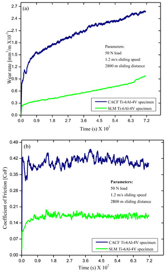
Figure 6.
Pin-on-disc wear study results: (a) wear rate and (b) coefficient of friction graph.
The COF graph as the function of sliding time for CACF and SLM Ti-6Al-4V specimens is shown in Figure 6b. The SLM specimen exhibited a lower COF of 0.16, whereas CACF specimens had a higher COF of 0.43 at 50 N load with 1.2 m/s slidings. A higher COF value shows a poor wear behaviour of the material property. In the present study, the CACF specimens exhibited higher COF and poorer wear behaviour than the SLM specimen. The COF was dependent on the variation in the microstructure formation, hardness, and strength of the material [26]. The overall trend of wear rate and COF with respect to sliding time was non-linear in nature. The major identification of the present work is that the two different manufacturing processes of Ti-6Al-4V alloy have different results with varying wear resistance under an externally applied load of 50 N.
3.5. Wear Track Examination
The worn out surfaces of CACF and SLM Ti-6Al-4V specimens were studied with the use of FESEM images (Figure 7). Figure 7 confirms that the wear tracks appear on both CACF and SLM Ti-6Al-4V specimens. It is observed that the largest width of the wear track is on the CACF specimens (Figure 7a). However, the wear track width was significantly smaller on the Ti-6Al-4V specimen produced by the SLM process (Figure 7b). The wear track of the CACF Ti-6Al-4V specimen appeared as a rough surface compared with the SLM Ti-6Al-4V specimen. Moreover, the worn out SLM specimen surface morphology was relatively smooth and aligned in the direction of the sliding movement. This outcome indicated that the CACF Ti-6Al-4V specimen had higher surface degradation which coincided with its hardness result (Figure 5) and the corresponding wear rate (Figure 6a). Relatively extended grooves appeared on the wear tracks of the CACF Ti-6Al-4V specimen which depended on the hardness of the hardened steel disc. Wear track widths varying from 10 µm to 50 µm and 10 µm to 20 µm were observed in the CACF and SLM specimens, respectively.
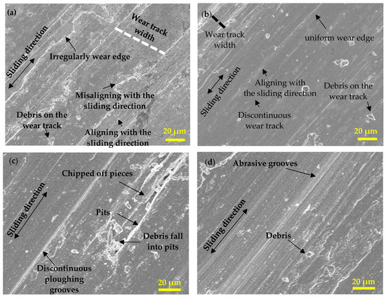
Figure 7.
Analysis of wear track width and debris: (a,b) CACF and SLM specimens. Analysis of worn out surface of: (c,d) CACF and SLM specimens at 50N load with 1.2m/s sliding speed.
The worn out surface of the SLM specimen (Figure 7b) appears as a smoother surface with less wear debris smeared on the wear track compared to the worn out surface of the CACF specimen in Figure 7a. The edges of the wear track of the CACF specimen were observed to be decorated irregularly with blown out pieces. However, these pieces were absent in the SLM specimen. In some other locations of the worn out surface of the CACF specimen, an uneven shape of the wear track was observed in which the width of the wear track varied in the length direction [27]. Figure 7a displays more irregular shapes of wear tracks. A similar type of irregular track shape had been stated by Niu et al. [28]. It revealed that the wear tracks of the CACF specimen were formed in a bumpy shape along the length of the wear track.
3.6. Wear Mechanism
A mixed mode of wear was observed in the case of the CACF specimen. Initially, the material was transferred from the Ti-6Al-4V specimen to the counter body due to its adhesive interaction. Deformation of the transfer layer due to a high degree of friction along with the high temperature gradient led to an increase in the frictional contact between the mating parts. As a result, the transferred material became more brittle and chipped off in the form of brittle wear debris, which can be observed as debris in Figure 7c. Deformation of the CACF Ti-6Al-4V surface increased with the increase in sliding contact time [29]. Consequently, the cohesive strength of the CACF Ti-6Al-4V surface gradually decreased. It resulted in the separation of large Ti-6Al-4V material fragments from the contact test surface. The brittle wear debris induced abrasive wear on the CACF specimen [30]. Irregular contact of the debris between the mating parts led to an increase in the hardness of the debris. Moreover, the wear debris was uneven in size and shape with a discontinuous form. This debris was pressed into the worn out surface during the dry sliding test, which may cause indent in the worn out surface. As a result, some of the pits were filled by the debris as can be seen in Figure 7c. Different sizes of wear debris were observed in the wear track of the CACF specimen. Moreover, this debris led to the production of ploughing grooves on CACF specimens. The temperature of the contact surface increased due to high strain during the wear test.
An FESEM image of the SLM specimen revealed that the metallic debris and oxide particles were formed under continuous sliding [31]. As a result, debris was accommodated on the worn out surface and produced the tribo-layers as viewed in Figure 7d. The result revealed that the debris originated from both the CACF and SLM specimens, out of which SLM had smaller-sized debris compared to the CACF specimen, as it possessed equiaxed grains. In addition to that, grooves, delamination particles, and pits on the worn out surfaces of the CACF and SLM specimens were observed in the FESEM images. A tribo-layer was formed due to oxidation and plastic deformation on the CACF and SLM specimens. SLM specimens showed a lesser delamination tendency of the subsequent surface of the SLM specimen during the pin-on-disc wear test. This result is correlated to its higher hardness (Figure 5) and higher wear resistance than the CACF specimens. According to Archard’s equation, the wear rate decreased as the hardness of the SLM specimen increased. More hardness was offered by the α-phase HCP structure in the SLM specimen which resulted in the reduction in the wear rate of the Ti-6Al-4V alloy. The SLM specimen possessed higher hardness due to the formation of α-phase fine microstructures (Figure 2c).
Based on the XRD analysis, the presence of the texture in the CACF specimen being significantly weakened was confirmed, as the intensity was 2.83 times less than that of the SLM specimen. Severe delamination occurred in the CACF specimen due to the generation of the primary crack during the wear test process that led to significant removal of material from the worn out surface (Figure 7c). Shear deformation was seen on the worn out surface of the CACF specimen. A negligible amount of delamination occurred in the SLM sample due to a lower amount of shear. The wear that occurred on the oxide layer led to a reduction in the wear rate of the SLM specimen. Moreover, it was ascribed to the development of a large number of horizontal and vertical cracks in the CACF specimen, resulting in severe delamination of the sub-region compared to the SLM specimen. Unlike the CACF specimen, the SLM specimen avoided the growth of primary cracks by exhibiting a uniform distribution of cracks which resulted in the formation of a few horizontal cracks. Even as the tribo-layers delaminated during the sliding test, new tribo-layers were grown at the nascent surface of the SLM specimen due to continuous loading that led to a reduction in the mass loss of the SLM specimen compared to the CACF specimen. Wear pit sizes of 80 to 100 µm and 5 to 10 µm were observed in the CACF and SLM specimens, respectively.
This wear mechanism is schematically represented in Figure 8a,b. During the pin-on-disc wear test, the material was deformed under continuous movement against the hard counter body. During the subsequent process, the fracture occurred by removal of the particles in the form of debris. Deformation and fracture were caused during the wear test. The tribo-layer, horizontal, and vertical cracks are highlighted in this figure, which are considered the most important factors affecting wear resistance of the CACF and SLM specimens. It is represented as the wear cracks and ploughing grooves on the sliding direction of the worn out surfaces of CACF and SLM specimens. A larger number of cracks was seen in the CACF specimen in the horizontal direction, which led to delamination during the continuous loading process. A limited number of cracks formed in the horizontal direction in the SLM specimen (Figure 8b), resulting in better resistance than the CACF specimen. Resistance to deformation without fracture is referred to as the hardness of the material. Formation of α-phase microstructures was the main reason for the reduction in the crack propagation behaviour of the SLM specimen.
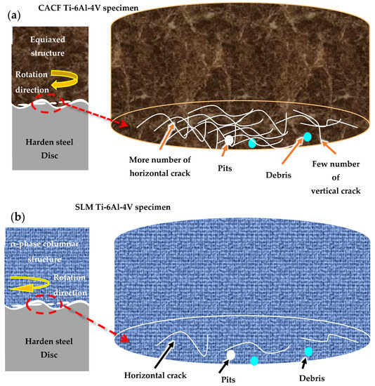
Figure 8.
Schematic representation of wear mechanism: (a,b) CACF and SLM specimens, respectively.
3.7. EDS Analysis of Worn out Surface
EDS analysis was performed on the worn out surfaces of both CACF and SLM specimens, and results are shown in Figure 9. The EDS analysis region is shown in the FESEM images (Figure 9a,b) of the CACF and SLM specimens. During the wear test, thermal oxidation has occurred on both the SLM and CACF specimens. EDS analysis (Figure 9c) on the worn out surface of the CACF specimen revealed that the tribo-layer possessed oxygen content. The presence of Fe content was much less in the tribo-layer, which confirmed that no Fe element had been released from the counter body steel disc to the CACF Ti-6Al-4V surface during the tribo-test. EDS analysis (Figure 9d) on the worn out surface of the SLM specimen revealed that the tribo-layer possessed higher oxygen content than the CACF specimen, which suggests that more oxidation wear happened on the SLM specimen than the CACF specimen during the dry sliding wear test. Moreover, the presence of Fe content was high in the tribo-layer, which might have been released from the counter body steel disc during the tribo-test. In addition to that, the EDS result for the tribo-layer confirmed the presence of carbon content as observed in Table 3. It shows that the carbon content is present in the tribo-layer. The carbon content that had formed in the tribo-layer may have come from the specimen surface which was exposed to a laboratory environment. EDS analysis indicated that titanium oxides were formed in the dry sliding wear condition [32]. Oxidation occurred normally in Ti-6Al-4V alloys that could lower the COF value of the SLM specimen by acting as a barrier between the Ti-6Al-4V specimen and the hardened steel [33]. The presence of the Fe element was higher than that of its initial value.
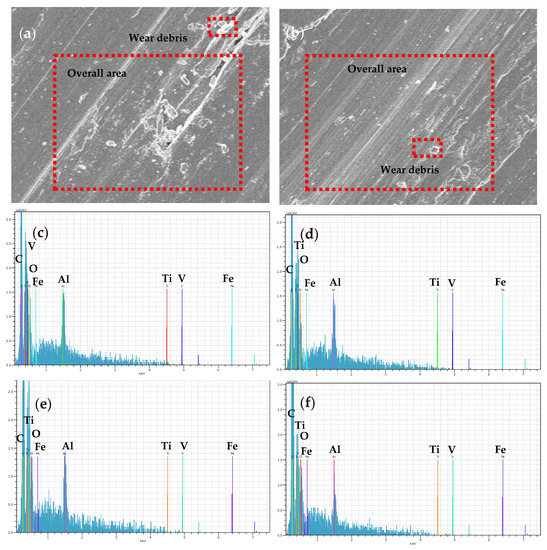
Figure 9.
EDS analysis on worn out surface: (a,b) micrograph of CACF and SLM specimens and their corresponding overall area scanning elemental graphs (c,d), respectively. (e,f) Wear debris elemental analysis of CACF and SLM specimens, respectively.
Table 3.
EDS analysis results of worn out surface of CACF and SLM specimens.
EDS analysis on the wear debris (Figure 9e) of the CACF specimen concluded that the particles possessed a higher percentage of Ti elements and a lower percentage of Fe elements. It revealed that the wear that occurred on the CACF specimens were delamination and abrasive modes of wear mechanisms. EDS analysis on the wear debris (Figure 9f) of the SLM specimen had shown that the Fe and oxygen elements present were higher than that of the CACF specimen. It shows that the wear that occurred on the SLM specimens was dominated by abrasive and oxidative modes of wear mechanisms. During the wear test, the Fe elements reacted with the oxygen elements which were present in the atmosphere and formed Fe2O3 layers. The Fe2O3 oxides were worn out during the abrasive action between the pin and the disc surface. In addition, the amount of material that was removed from the CACF surface during the wear test is greater than that of the SLM specimen. As a result, the old layers were removed, and the new layer of material appeared with the formation of more grooves on the worn out surface. The EDS results were carried out on the worn out surface where the new composition of the material appeared. Hence, the Fe content was significantly less in Table 3 compared to Table 2.
3.8. Roughness Measurement
The mechanism involved during the tribological test was dependent on the mechanical properties, shape, and size of the asperities. In the present work, the roughness value (Sa) was measured to analyse the surface roughness of the worn out surface. Higher Sa value was directly proportional to the slenderness of the asperities [34]. Three-dimensional topography and corresponding two-dimensional diagrams of the worn out surface of CACF specimens and SLM specimens are shown in Figure 10. Grooves and pits were observed in the 3D topography of both the specimens. However, a greater number of grooves were observed in the CACF specimen (Figure 10a) than the SLM specimen (Figure 10c). Similarly, a large number of peaks and valleys were seen in the 2D graph of the CACF specimen (Figure 10b). In addition, the Sa values of SLM and CACF specimens were measured as 8.94 μm and 10.58 μm, respectively. The result revealed that the SLM specimen had less roughness (Figure 10d) compared with the CACF specimen due to a lower wear rate [35]. Adhesive and abrasive wear occurred dominantly in the CACF specimen, whereas abrasive wear occurred dominantly in the SLM specimen. Moreover, SLM processing parameters influenced the reduction in the asperities on the SLM specimen.
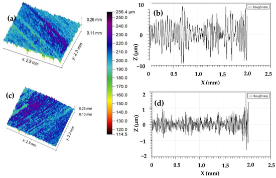
Figure 10.
Worn out 3D topographies and their corresponding 2D roughness profiles: (a,b) CACF specimen and (c,d) SLM specimen.
4. Conclusions
The Ti-6Al-4V specimens were successfully manufactured using SLM techniques. Microstructure, micro- and nanohardness, and wear behaviour of SLM-based Ti-6Al-4V specimens have been investigated and compared with the CACF Ti-6Al-4V specimen. The mechanism correlating microstructure and wear behaviour of CACF and SLM-based Ti-6Al-4V specimens have been explained. Based on the above investigation, the following conclusions are derived:
- The SLM process had been used to facilitate the growth of a fully columnar structure. The application of SLM enhanced the microstructural homogeneity and considerably diminished the growth of β-grain size. It led to a reduction in the solidification texture of β-grain. The SLM Ti-6Al-4V specimen had Widmanstatten structures, martensitic rectangular structures, and β-phases. The overall microstructure of the SLM specimen was viewed as a basket-weave microstructure.
- Equiaxed α-phase was formed in most of the regions of the CACF specimen. The distribution of Ti elements was majorly segregated in some regions of the CACF Ti-6Al-4V specimen, whereas uniformly distributed throughout the region of the SLM specimen. The SLM specimen showed more broadened peaks than that of the CACF specimen due to the presence of the martensite phase.
- The average microhardness of the CACF specimen and the SLM specimen was 380.7HV0.1 and 466.2HV0.1, respectively. The SLM-based deposited Ti-6Al-4V had a nanohardness of 4.47 GPa, whereas the CACF specimen had a nanohardness of 3.16 GPa.
- The SLM specimen had a lower wear rate of 0.892 × 10⁻³ mm3·N−1·m−1 compared to the CACF specimens. The SLM specimen exhibited a lower COF of 0.16, whereas CACF specimens had a higher COF of 0.43 at 50 N load with 1.2 m/s sliding.
- Finer needle-like microstructures of the specimen produced using the SLM process had higher wear resistance as they had higher hardness than the CACF specimen. Deep horizontal cracks were observed in the CACF specimen, resulting in delamination wear owing to the higher wear initiated by the sub-surface cracks. On the other hand, the SLM specimen exhibited a few horizontal cracks.
Author Contributions
N.J.: conceptualization, methodology, software, validation, investigation, writing—original draft, writing—review and editing, and visualization. C.-H.Y.: conceptualization, writing—review and editing, visualization, supervision, and funding acquisition. G.P.: conceptualization, methodology, validation, investigation, and writing—review and editing. N.R.: conceptualization, methodology, and visualization. All authors have read and agreed to the published version of the manuscript.
Funding
This research received no external funding.
Institutional Review Board Statement
Not applicable.
Informed Consent Statement
Not applicable.
Data Availability Statement
The experimental datasets obtained from this research work and the results analysed during the current study are available from the corresponding author on reasonable request.
Acknowledgments
We are grateful for the support from the Priority Academic Program Development of Jiangsu Higher Education Institutions, China.
Conflicts of Interest
The authors declare no conflict of interest.
References
- Leyens, C.; Peters, M. Titanium and Titanium Alloys: Fundamentals and Applications; Wiley-VCH Verlag GmbH: Cologne, Germany, 2003. [Google Scholar]
- Niu, Q.L.; Zheng, X.H.; Ming, W.W.; Chen, M. Friction and wear performance of titanium alloys against tungsten carbide under dry sliding and water lubrication. Tribol. Trans. 2013, 56, 101–108. [Google Scholar] [CrossRef]
- Dong, H. Tribological Properties of Titanium-Based Alloys, Surface Engineering of Light Alloys; Woodhead Publishing Limited: Oxford, UK, 2010; pp. 58–80. [Google Scholar]
- Tuck, C.; Hague, R.; Burns, N. Rapid manufacturing: Impact on supply chain methodologies and practice. Int. J. Serv. Oper. Manag. 2007, 3, 1–22. [Google Scholar] [CrossRef]
- Bartolomeu, F.; Buciumeanu, M.; Pinto, E.; Alves, N.; Silva, F.S.; Carvalho, O.; Miranda, G. Wear behaviour of Ti6Al4V biomedical alloys processed by selective laser melting, hot pressing and conventional casting. Trans. Nonferrous Met. Soc. China 2017, 27, 829–838. [Google Scholar] [CrossRef]
- Xu, Z.; Cao, L.; Zhu, Q.; Guo, C.; Li, X.; Hu, X.; Yu, Z. Creep property of Inconel 718 superalloy produced by selective laser melting compared to forging. Mater. Sci. Eng. A 2020, 794, 139947. [Google Scholar] [CrossRef]
- Husain, N.A.-H.; Feilzer, A.J.; Kleverlaan, C.J.; Abou-Ayash, S.; Özcan, M. Effect of hydrothermal aging on the microhardness of high and low-viscosity conventional and additively manufactured polymers. J. Prosthet. Dent. 2022, 128, 822.e1–822.e9. [Google Scholar] [CrossRef]
- Palanisamy, C.; Bhero, S.; Obadele, B.A.; Olubambi, P.A. Effect of build direction on the microhardness and dry sliding wear behaviour of laser additive manufactured Ti-6Al-4V. Mater. Today Proc. 2018, 5, 397–402. [Google Scholar] [CrossRef]
- Boyer, R.; Welsch, G.; Collings, E.W. (Eds.) Materials Properties Handbook: Titanium Alloys; ASM International: Materials Park, OH, USA, 1994. [Google Scholar]
- Jovanovic, M.T.; Tadic, S.; Zec, S.; Miskovic, Z.; Bobic, I. The effect of annealing temperatures and cooling rates on microstructure and mechanical properties of investment cast Ti–6Al–4V alloy. Mater. Des. 2006, 27, 192–199. [Google Scholar] [CrossRef]
- Vastola, G.; Zhang, G.; Pei, Q.X.; Zhang, Y.W. Active Control of Microstructure in Powder-Bed Fusion Additive Manufacturing of Ti6Al4V. Adv. Eng. Mater. 2017, 19, 1700333. [Google Scholar] [CrossRef]
- Hooper, P.A. Melt pool temperature and cooling rates in laser powder bed fusion. Addit. Manuf. 2018, 22, 548–559. [Google Scholar] [CrossRef]
- Yule, A.J.; Dunkley, J.J. Atomization of Melts for Powder Production and Spray Deposition; Oxford University Press: Oxford, MS, USA, 1994. [Google Scholar]
- Gong, X.; Lydon, J.; Cooper, K.; Chou, K. Beam speed effects on Ti-6Al-4V microstructures in electron beam additive manufacturing. J. Mater. Res. 2014, 29, 1951–1959. [Google Scholar] [CrossRef]
- Baufelda, B.; van der Biesta, O.; Gaultb, R. Microstructure of Ti-6Al-4V specimens produced by shaped metal deposition. Int. J. Mater. Res. 2009, 100, 1536–1542. [Google Scholar] [CrossRef]
- Reichardt, A.; Dillon, R.P.; Borgoni, J.P.; Shapiro, A.A.; McEnerney, B.W. Development and characterization of Ti-6Al-4V to 304L stainless steel gradient components fabricated with laser deposition additive manufacturing. Mater. Des. 2016, 104, 404–413. [Google Scholar] [CrossRef]
- Li, P.H.; Guo, W.-G.; Huang, W.-D.; Su, Y.; Lin, X.; Yuan, K.-B. Thermomechanical response of 3D laser-deposited Tie6Ale4V alloy over a wide range of strain rates and temperatures. Mater. Sci. Eng. A 2015, 647, 34–42. [Google Scholar] [CrossRef]
- Ding, L.; Hu, R.; Gu, Y.; Zhou, D.; Chen, F.; Zhou, L.; Chang, H. Effect of Fe Content on the As-Cast Microstructures of Ti–6Al–4V–xFe Alloys. Metals 2020, 10, 989. [Google Scholar] [CrossRef]
- Szkliniarz, A.; Szkliniarz, W. Carbon in Commercially Pure Titanium. Materials 2023, 16, 711. [Google Scholar] [CrossRef] [PubMed]
- Murr, L.E. Microstructure and mechanical behavior of Ti-6Al-4V produced by rapid-layer manufacturing, for biomedical applications. J. Mech. Behav. Biomed. Mater. 2009, 2, 20–32. [Google Scholar] [CrossRef] [PubMed]
- Jeyaprakash, N.; Yang, C.-H.; Ramkumar, K.R. Microstructural, mechanical and wear behaviour of Inconel-718 produced through laser-powder bed-fused additive manufacturing. Mater. Sci. Technol. 2021, 37, 326–337. [Google Scholar] [CrossRef]
- Kumar, P.; Ramamurty, U. Microstructural optimization through heat treatment for enhancing the fracture toughness and fatigue crack growth resistance of selective laser melted Ti-6Al-4V allo. Acta Mater. 2019, 169, 45–59. [Google Scholar] [CrossRef]
- Lu, S.L.; Zhang, Z.J.; Liu, R.; Qu, Z.; Wang, B.; Zhou, X.H.; Eckertc, J.; Zhang, Z.F. Prior β grain evolution and phase transformation of selective laser melted Ti6Al4V alloy during heat treatment. J. Alloy. Compd. 2022, 914, 165235. [Google Scholar] [CrossRef]
- Semiatin, S.L.; Seetharaman, V.; Weiss, I. The thermomechanical processing of alpha/beta titanium alloys. JOM—J. Miner. Met. Mater. Soc. 1997, 49, 33–39. [Google Scholar] [CrossRef]
- Murugesan, P.; Satheeshkumar, V.; Jeyaprakash, N.; Prabu, G.; Yang, C.-H. Nano-level mechanical and tribological behavior of additively manufactured AlSi10Mg plates. Arch. Civ. Mech. Eng. 2023, 23, 62. [Google Scholar] [CrossRef]
- Chapala, P.; Sunil Kumar, P.; Joardar, J.; Bhandari, V.; Ghosh Acharyya, S. Effect of alloying elements on the microstructure, coefficient of friction, in-vitro corrosion and antibacterial nature of selected Ti-Nb alloys. Appl. Surf. Sci. 2019, 469, 617–623. [Google Scholar] [CrossRef]
- Prabu, G.; Duraiselvam, M.; Jeyaprakash, N.; Yang, C.-H. Microstructural Evolution and Wear Behavior of AlCoCrCuFeNi High Entropy Alloy on Ti–6Al–4V Through Laser Surface Alloying. Met. Mater. Int. 2021, 27, 2328–2340. [Google Scholar] [CrossRef]
- Niu, Q.L.; Zheng, X.H.; Chen, M.; Ming, W.W. Study of the tribological properties of titanium alloys sliding against WC-Co during the dry friction. Ind. Lubr. Tribol. 2014, 66, 202–208. [Google Scholar] [CrossRef]
- Jeyaprakash, N.; Yang, C.-H.; Prabu, G.; Clinktan, R. Microstructure and Tribological Behaviour of Inconel-625 Superalloy Produced by Selective Laser Melting. Met. Mater. Int. 2022, 28, 2997–3015. [Google Scholar] [CrossRef]
- Jeyaprakash, N.; Yang, C.-H.; Duraiselvam, M.; Prabu, G. Microstructure and tribological evolution during laser alloying WC-12% Co and Cr3C2− 25% NiCr powders on nodular iron surface. Results Phys. 2019, 12, 1610–1620. [Google Scholar] [CrossRef]
- Rodríguez, J.S.; Duran, J.F.; Aguilar, Y.; Alcazar, G.A.P.; Toro, A.; Zambrano, O.A. Effect of Al content on the low-stress abrasive wear behaviour of Fe-18Mn-xAl-0.7C alloys. Tribol. Int. 2023, 180, 108286. [Google Scholar] [CrossRef]
- Evtushenko, O.; Kazachenok, M.; Buslovich, D.; Martynov, S. Effect of Oxidation on Wear Resistance of 3D-Printed Titanium Alloy Ti-6Al-4V Parts. In AIP Conference Proceedings; AIP Publishing LLC, Woodbury: Long Island, NY, USA, 2019; Volume 2167, p. 020094. [Google Scholar]
- Souza, J.C.M.; Henriques, M.; Teughels, W.; Ponthiaux, P.; Celis, J.P.; Rocha, L.A. Wear And Corrosion Interactions On Titanium In Oral Environment: Literature Review. J. Bio- Tribo-Corros. 2015, 1, 13. [Google Scholar] [CrossRef]
- Jeyaprakash, N.; Prabu, G.; Yang, C.H. The Influence of Different Phases on the Microstructure and Wear of Inconel-718 Surface Alloyed with AlCuNiFeCr Hard Particles Using Plasma Transferred Arc. J. Mater. Eng. Perform 2022, 31, 9921–9934. [Google Scholar] [CrossRef]
- Jeyaprakash, N.; Yang, C.-H.; Ramkumar, K.R. Correlation of Microstructural Evolution with Mechanical and Tribological Behaviour of SS 304 Specimens Developed Through SLM Technique. Met. Mater. Int. 2021, 27, 5179–5190. [Google Scholar] [CrossRef]


Disclaimer/Publisher’s Note: The statements, opinions and data contained in all publications are solely those of the individual author(s) and contributor(s) and not of MDPI and/or the editor(s). MDPI and/or the editor(s) disclaim responsibility for any injury to people or property resulting from any ideas, methods, instructions or products referred to in the content. |
© 2023 by the authors. Licensee MDPI, Basel, Switzerland. This article is an open access article distributed under the terms and conditions of the Creative Commons Attribution (CC BY) license (https://creativecommons.org/licenses/by/4.0/).