Article

Impact of Isothermal Aging on Mechanical Properties of 92.8%Sn-3%Ag-0.5%Cu-3.3%Bi (Cyclomax) Solder Joints

by
Mohammad M. Hamasha
1,
Khozima Hamasha
2,* and
Sa’d Hamasha
3
1
Department of Industrial Engineering, Faculty of Engineering, The Hashemite University, Zarqa 13133, Jordan
2
Department of Basic Scientific Sciences, Al-Huson University College, Al-Balqa Applied University, Al-Salt 19117, Jordan
3
Department of Industrial and Systems Engineering, Auburn University, Auburn, AL 36849, USA
*
Author to whom correspondence should be addressed.
Metals 2023, 13(3), 591; https://doi.org/10.3390/met13030591
Submission received: 22 January 2023 / Revised: 12 March 2023 / Accepted: 13 March 2023 / Published: 14 March 2023

Abstract

:
During operation, electronic components are exposed to high temperatures that may last for long periods, depending on the operating duration. Solder joints are one of the components most affected by thermal aging while in service. In this research, the effect of thermal aging duration and temperature on the mechanical properties of 92.8%Sn-3%Ag-0.5%Cu-3.3%Bi (Cyclomax) was investigated. The novelty of this work lies in the study of the important properties of a new generation of Sn-Ag-Cu (SAC) materials (i.e., Cyclomax). Cyclomax is rare in industry and immature in research. To understand the effect of thermal aging, the microstructure was investigated, and changes in it and its mechanical properties were observed. To simulate solder joints in electronic devices, samples of solder balls were prepared and attached to copper pads on electronic boards. Most samples were then treated at 150 °C or 100 °C for up to 1000 h and some samples were left untreated for comparison. A scanning electron microscope (SEM) was used to obtain images of the microstructure. The shear stress–shear strain relationships, including the ultimate shear strength (USS), the modulus of elasticity and the ultimate energy (UE), were investigated. The microstructure images indicated the presence of a layer of Cu6Sn5 on top of the copper pad before thermal aging was applied. The thickness of this layer increased with the application of thermal aging over time. The results for the shear stress–shear strain relationship indicate that all of the USS, the total energy (TE) to shear off the solder balls and the UE decreased at the beginning of the thermal aging and then reversed to increase later. In general, isothermal aging reduces the performance of Cyclomax solder joints in terms of the minimum force and energy required to separate and subsequently damage electronic components.

1. Introduction

A printed circuit board (PCB) is a motherboard on which electrical circuits are etched and various electronic components are installed. To connect the electronic components on a PCB, solder joints are necessary. However, the solder joints are the weakest points that can be exposed to high heat during the operation of the devices for long periods if they run for a long time [1,2,3,4]. The weakness of these joints is due to the nature of the materials used in their manufacture, which mainly contain tin, which melts at a low temperature.
In the electronics industry, electronic packaging is one of the most important aspects that cannot be underestimated for two reasons. The first is that electronic packaging provides electrical connections with precise electronic measurements, such as voltage and resistance, and the second is that electronic packaging provides mechanical support for the various components of the PCB [5]. Furthermore, the need to focus on electronic packaging increases with the increasing complexity of electronics and tends to reduce their size [6]. Electronic packaging developed tremendously during the 21st century and is still developing rapidly [7].
Over the years, solder joint materials have been developed to overcome the mechanical characteristics and reliability challenges. Tin materials used for soldering consist of two generations: lead-tin and lead-free solder joints. The lead–tin alloy commonly used in electric soldering is 60/40 Sn-Pb, which melts at 188 °C, and 63/37 Sn-Pb, which is mainly used in precise electrical/microelectronic work. The second alloy is eutectic and easy to manufacture. Because of environmental concerns, the world began to use lead-free solder joints, which are the second generation. For example, the European Union restricted the use of lead-based solder joints in 2003. These joints may commonly contain tin, copper and silver and may contain other trace elements, such as bismuth, indium, zinc and antimony. Regardless of the design of the electronic board and its components, the solder joints’ mechanical, electrical and thermal loads have certain levels that cannot be exceeded. Furthermore, with the replacement of lead-based materials with lead-free solder materials, the thermal and mechanical loads have decreased [8]. Therefore, a large number of studies have been conducted to develop the properties of lead-free alloys, such as [9,10,11,12,13,14,15,16].
Due to the role that solder joints play in connecting the various electronic elements with the electronic board, a damaged solder joint or poor conduction of electric current is considered dangerous for the function of the electronic device as a whole. Therefore, its long-term reliability is the focus of research and manufacturing. Stress failure on the solder joint is prevalent in electronic industries in areas exposed to operating temperatures. Therefore, there is a real need to evaluate this effect in addition to preparing reliable, consistent and comprehensive foundation equations for materials before use, which leads to an evaluation of their reliability and process improvement. This requires great effort because investigating solder joints is difficult in practice due to the difficulties of preparing test samples that simulate the reality of electronic devices.
The reliability of solder joints poses a major challenge during the process of replacing lead-based materials with lead-free materials. Solder joints made of lead-free materials are less reliable than solder joints made of lead-based materials. Therefore, researchers are working to stop the degradation in the joints of lead-free materials, including evaluating the influencing factors and attempting to reduce their impact and using cooling if necessary [17]. Improving the reliability includes producing solder joints that are resistant to continuous heat [18,19,20] and fluctuating heat [21,22,23], vibration [24,25] and electric shocks that cause cutting joints [26,27].
Among lead-free alloys, Sn-Ag-Cu (SAC) alloys are the most widely used due to their ease of fabrication and abundancy [13]. SAC (Sn-Ag-Cu)-based solder alloys are widely used as lead-free alloys due to their good properties and environmental compliance. The mechanical properties of SAC-based alloys are critical in electronic industries. This literature review will focus on recent research studies that have studied the mechanical properties of SAC-based alloys. Many authors have worked on the tensile strength of SAC-based alloys. They reported that the tensile strength increases with Ag content. For example, Yang et al. [28] reported that the tensile strength of SAC305 (3.0 wt.% Ag) is greater than that of SAC105 (1.0 wt.% Ag). Additionally, the addition of Cu to SAC-based alloys can further improve their tensile strength [29]. However, excessive Cu content may cause a decrease in the tensile strength due to the development of brittle intermetallic compounds (IMCs) [30]. The shear strength of SAC-based alloys is also an important mechanical property. Studies have shown that increasing Ag content increases the shear strength of SAC-based alloys [31]. Moreover, the addition of small amounts of Zn can also improve the shear strength of SAC-based alloys [32]. However, excessive Zn content may cause a decrease in shear strength due to the formation of brittle IMCs [32]. The fatigue strength of SAC-based alloys is critical in determining the long-term reliability of electronic devices. Studies have shown that the addition of Ag can improve the fatigue strength of SAC-based alloys [33]. Additionally, the addition of small amounts of Ni can also improve the fatigue strength of SAC-based alloys [34]. However, excessive Ni content may cause a decrease in the fatigue strength due to the formation of brittle IMCs [34].
Many studies focus on effect of thermal aging on SAC-based alloys, as in the following example. Long et al. [35] studied the effect of thermal aging on the tensile behavior of a material for SAC and then compared it with welding Sn-37Pb. The tensile strength is greatly improved after thermal aging. Long et al. [36] investigated the effect of thermal aging on residual stresses of SAC-based alloys. Long et al. [37] optimized the eutectic of SAC alloys. Furthermore, many researchers are working to develop the properties of these alloys by doping them with other materials, such as Ni, Bi and Sb [38]. The most common SAC alloys doped with other materials are Cyclomax, Innolot, Ecolloy and SAC-X-Plus [39,40,41]. Cyclomax has the following mass percentages: 92.77Sn-3.41Ag-0.52Cu-3.3Bi.
Several researchers have evaluated the effects of adding Bi to SAC alloys. The formed Cyclomax solder alloy showed better ultimate shear strength (USS) compared to the SAC305 alloy [41]. Moreover, the same alloys showed better resistance to crack formation and propagation [42]. In a study conducted by Rizvi et al. [43] to evaluate the effect of adding 1% bismuth, the results showed a slowdown in the growth rate of the intermetallic compound (IMC) layer by reducing the consumption of copper, in addition to reducing the melting temperature of the solder. Another study showed an increase in the thermal stress lifetime and a drop in shock reliability with the addition of Bi and Ni [44]. Moreover, the addition of Bi increases the tensile strength and reduces the elongation of the solder, as reported in [45]. The addition of Bi has been shown to improve the wettability of the SAC alloy [46].
Overall, Cyclomax solder alloys have been found to exhibit improved mechanical, thermal, and reliability properties, making them a promising candidate for use in various electronic packaging applications. However, more research is needed to fully understand the effects of Bi addition on the properties of SAC alloys and to optimize the composition of these alloys for specific applications.
In this paper, thermal aging has been applied to Cyclomax solder joints. The changes in microstructure and mechanical properties induced by thermal aging were studied. This research is important to simulate the effect of long-term operating temperatures on solder joints if they are adopted by industry. There is very little information about the exact structure and mechanical properties of Cyclomax in the literature, and this paper can help bridge the knowledge gap. In addition, the results published in this paper can be compared with the results of SAC-based alloys published in [47] and the usefulness of adding the BI element can be evaluated from several aspects.

2. Experimental Procedure

Thermal aging was applied at temperatures of 150 °C and 100 °C for different durations: 2, 10, 100 and 1000 h. For comparison, some samples did not undergo thermal aging. After aging, cross sections of selected samples were prepared for electron microscopy. Then, mechanical tests were carried out on other samples using the Instron. A temperature of 150 °C represents the maximum temperature when operating electronic devices. Therefore, the research focuses on this possible higher temperature (i.e., the worst-case scenario). Moreover, the duration of 1000 h is a very long aging time for the SAC alloy, which ensures the steady-state condition is reached. This explanation was added to the text.

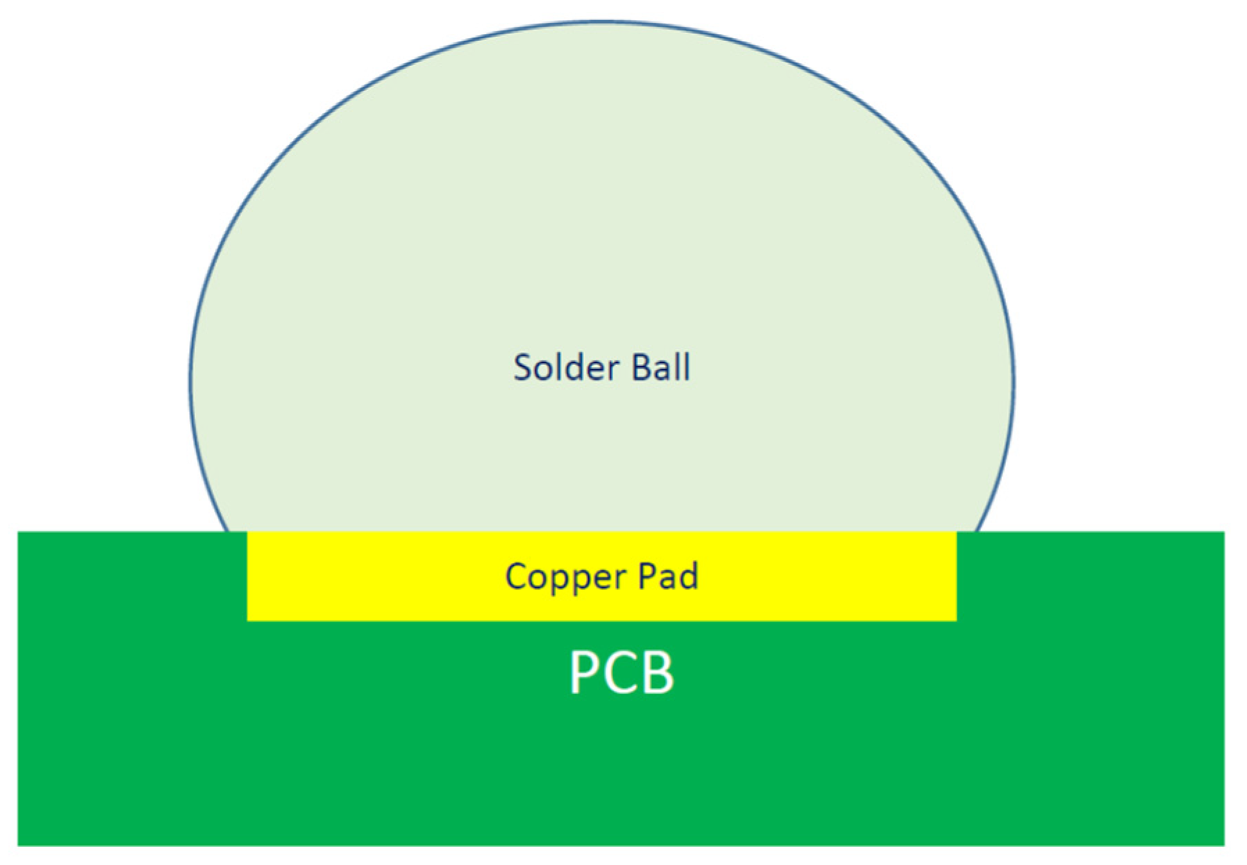
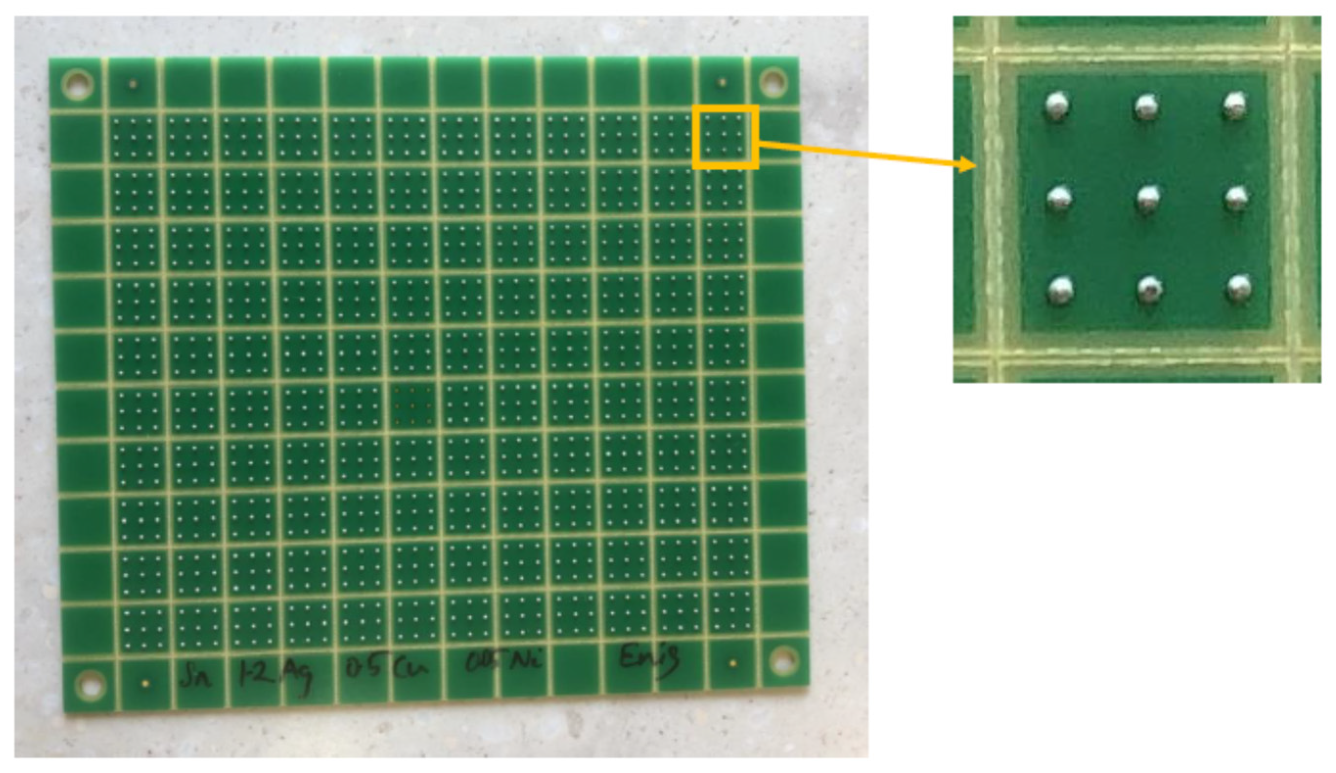
2.1. Sample Preparation

Cyclomax (92.8%Sn-3%Ag-0.5%Cu-3.3%Bi) solder balls with a diameter of 30 mils were prepared and fixed on copper pads (PCB Chart, Hangzhou, China) with a diameter of 22 mils and then implanted on printed circuit boards (PCBs) (PCB Chart, Hangzhou, China) to simulate reality. The balls were exposed to 245 °C, which is higher than the melting point, for a period of 45 s, to remelt the balls over the copper pads. The shape of the balls fixed to the copper pads after the remelting process is shown in Figure 1.

2.2. Thermal Aging

Ten test PCBs were prepared. Each test BCB contained 120 squares, and each square contained 9 solder balls attached to a copper pad as shown in Figure 2. The size of the square is 393 × 393 mils. The test BCBs were then placed in controlled temperature ovens (Esco Technologies Pty Ltd., Centurion, South Africa). The temperature and duration were controlled. The selected temperatures were 100 and 150 °C, and the selected durations were 0, 2, 10, 100 and 1000 h. A single board with over 1000 solder joints was used for each combination of temperatures and durations.

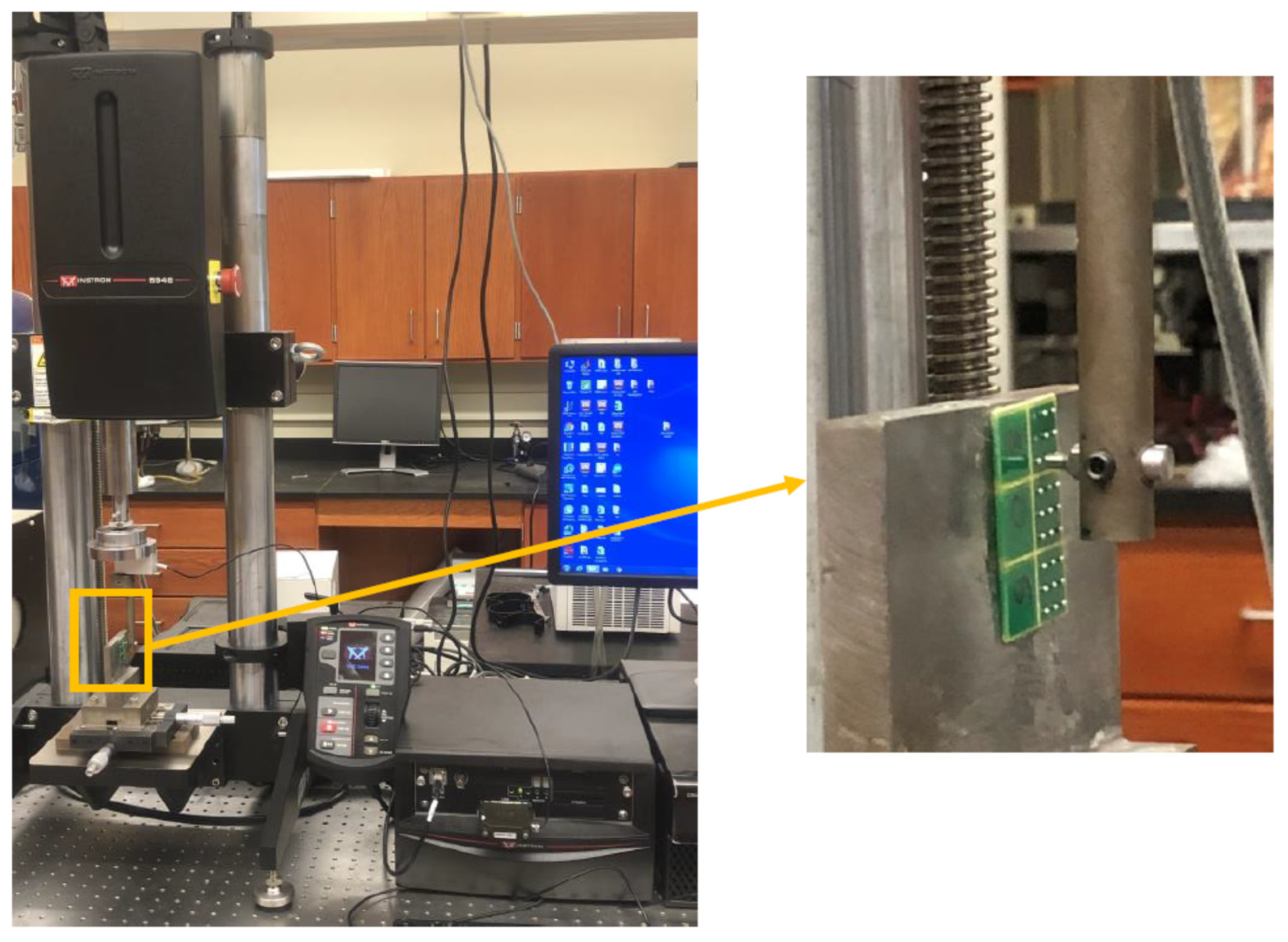
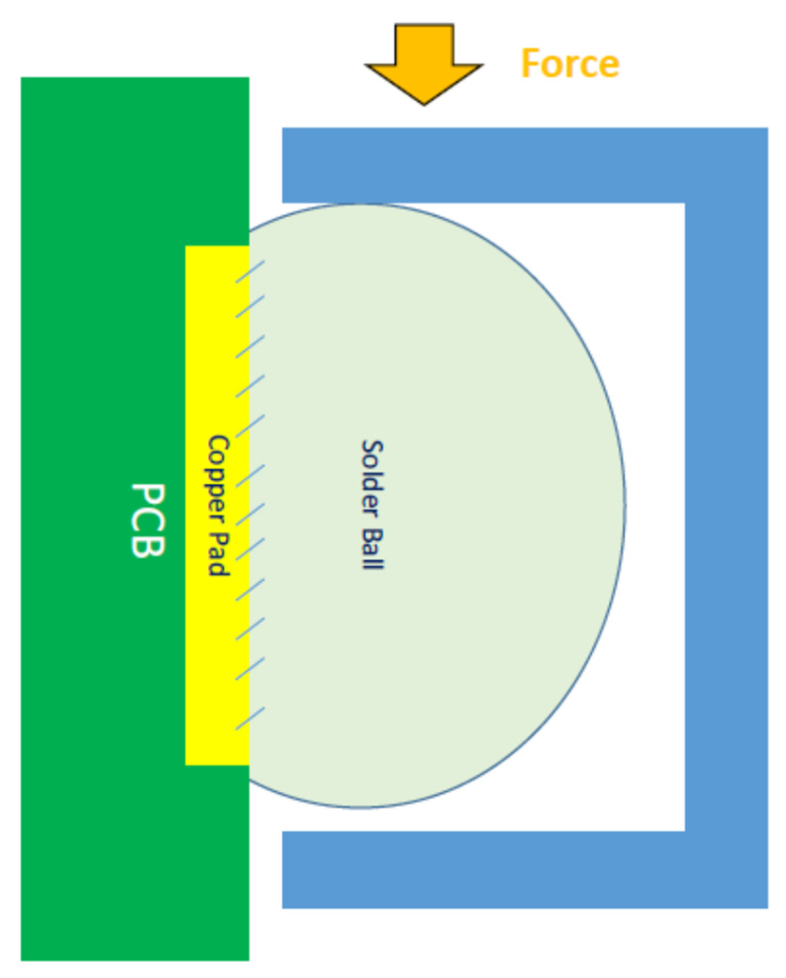
2.3. Shear Strength Test

In this study, a shear strength test was used to shear the solder joints from the copper pads in a horizontal direction. Shear strength is one of the most important indicators of reliability. An Instron 5948 Micro-Mechanical device (Instron, Norwood, MA, USA) was used to perform the tests (shown in Figure 3). With the help of Minitab 19.2020.1, the sequence of solder joints for the test was randomly arranged before the shearing began to ensure that the noise factors were neutralized. The device contains a special fixture that is specially designed to hold the board. Shear strength was measured continuously using a 50 N load cell. The JESD22-B117 standard was considered in this study. The amount of shear applied to the solder joint is shown in Figure 4.
A shear strain rate of 0.01 s–1 was chosen. This rate is slow enough to accurately describe the shear stress–shear strain curve and minimize the error in it. The strength was monitored continuously until the solder joint was completely disconnected from the copper pad. Based on previous recommendations, a cutting height of 0.05 mm was chosen.
Scanning electron microscopy (SEM) (Carl Zeiss Vision UK Ltd., Birmingham, United Kingdom) was used to characterize the microstructure of Cylomax. It is a kind of imaging technique that uses a focused beam of electrons to scan the surface of a sample and create a high-resolution image. The following are the steps performed in pictures: The samples were cut at the solder ball, polished, cleaned and dried. The sample was mounted on the metal holder using a conductive adhesive. Then, the sample was inserted into the SEM chamber. The SEM chamber was unloaded. Then, various settings were adjusted, such as voltage, beam current and working distance, to optimize imaging conditions for the selected sample. The electron beam was then scanned through the sample, and the resulting signal was collected and used to form an image. Energy-dispersive X-ray spectroscopy analysis (EDXA) (Carl Zeiss Vision UK Ltd., Birmingham, United Kingdom) was conducted. EDXA is a valuable tool in materials science, providing important information about the elemental composition of a sample. The technique has numerous applications in various fields, including metallurgy, biology and environmental science. With advances in technology, EDXA has become faster, more accurate and more sensitive, making it an essential tool in modern materials science.

3. Results and Discussion

The results for the microstructure and the mechanical properties of Cyclomax are discussed. Cyclomax is a lead-free solder that is an advanced version of SAC-based alloys. It is currently under investigation for initiation into industry. The alloy consists of the following elements: 92.8% Tin, 3% Ag, 0.5% Copper, 3.3% Ni, and the remaining 0.4% are traces of other metals. The section is divided into two subsections.

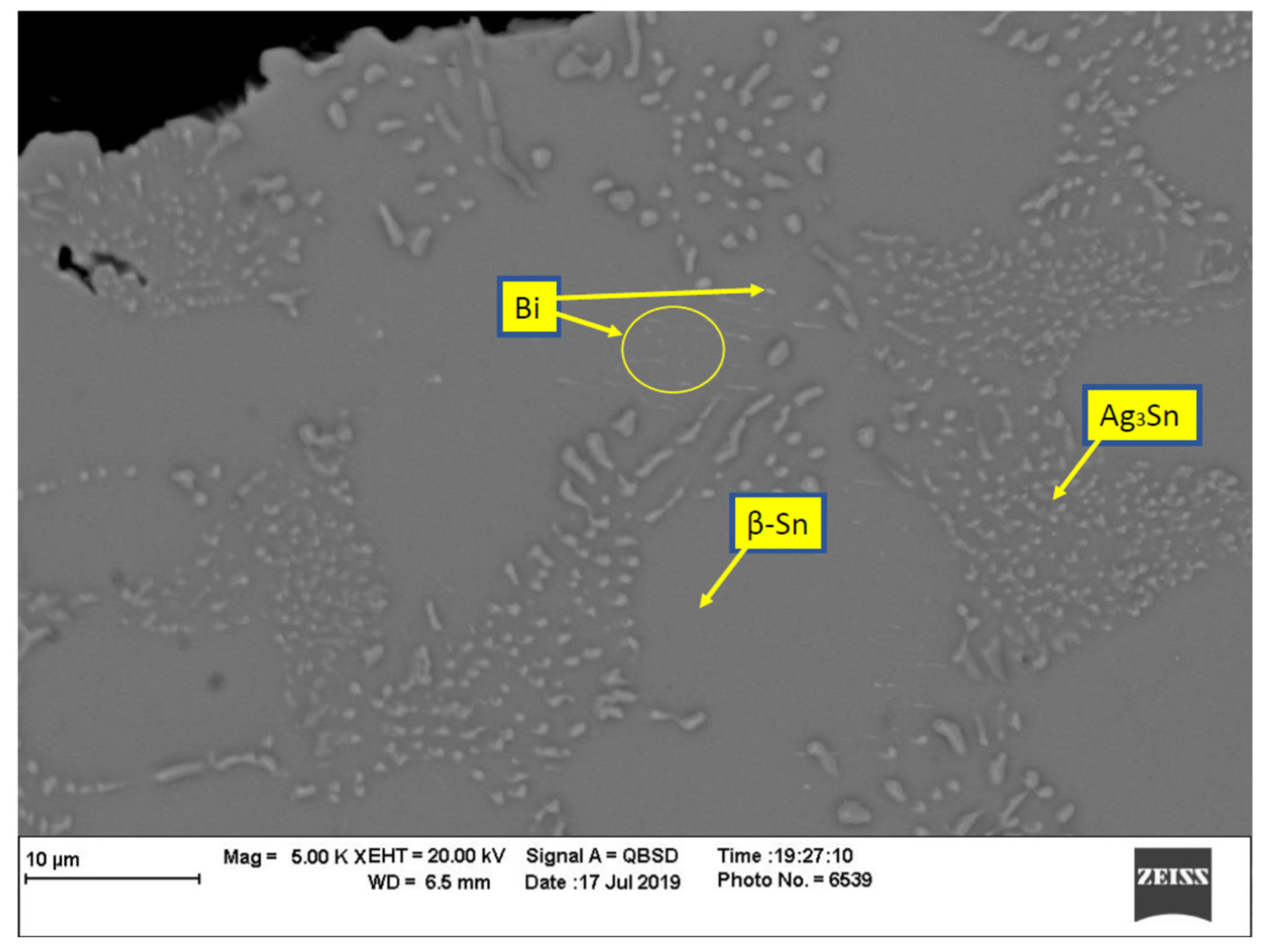
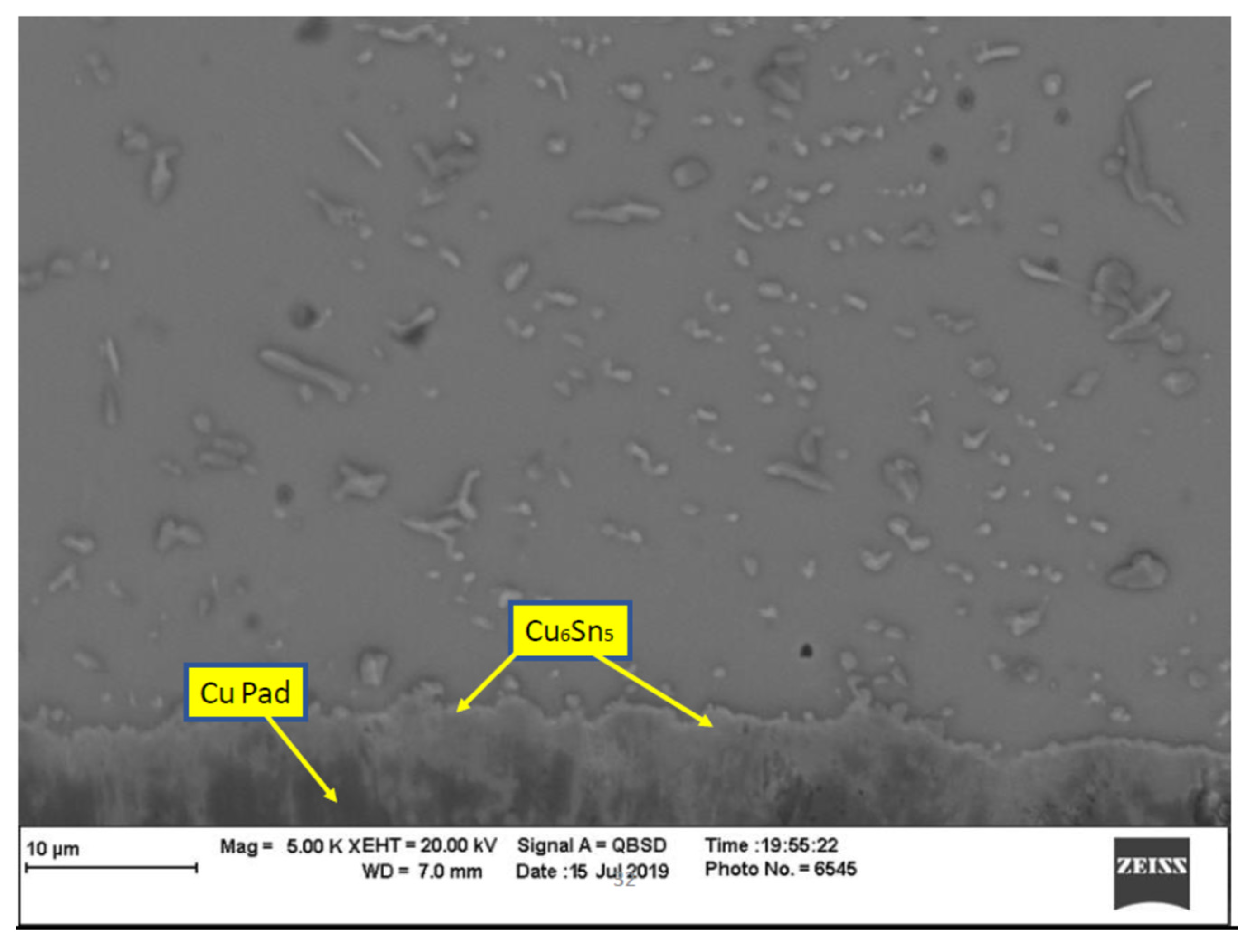
3.1. Effect of Thermal Aging on the Cyclomax Microstructure

The evaluation of the effect of thermal aging on Cyclomax began with observations of the changes in the microstructure. A scanning electron microscope was used. The microstructure of as-prepared Cyclomax consists of three phases, as shown in Figure 5: Ag3Sn, β-Sn and Bi. The β-Sn phase occupies all of the microstructure, but it is remarkable for its presence as spots that are completely devoid of the other two phases. In contrast, the Ag3Sn phase has protrusions permeating the β-Sn phase, forming spots that are different from the pure β-Sn spots. Bi exists in pure form, distributed as very fine white dots scattered on the microstructure. The microstructure of the cross section of the contact area of the copper pad with the Cyclomax sphere is shown in Figure 6. There appears to be fusion between copper and Cyclomax by the diffusion of copper atoms inside the Cylomax, which forms an IMC layer of Cu6Sn5. EDXA was conducted and the results are shown in Table 1.
The application of heat for a long time allows the spread of atoms to make a significant change in the stages of the materials. What drives the atoms to spread is to reach the lowest energy situation. The development of stages really changes the mechanical, chemical and physical properties. The microstructure of Cyclomax after thermal aging is applied at 150 °C for 100 h is shown in Figure 7, and the microstructure of the copper-Cyclomax junction for the same sample is shown in Figure 6. As shown in Figure 7, many developments on Cyclomax were observed, such as shrinking of the area of pure β-Sn spots, an increase in the size of the Ag3Sn bumps and an increase in the size of the Bi dots. Moreover, the formation of a clear layer of Cu6Sn5 between copper and Cylomax is also shown in Figure 6. Figure 8 shows the microstructure of the junction zone between Cyclomax and the copper pad of a sample that underwent heat aging for 100 h. These developments increased with the increase in the thermal aging duration to 1000 h, as shown in Figure 9 and Figure 10. The pure β-Sn spots are reduced to a minimum, and the Ag3Sn bumps are very large and distributed over almost all areas of the microstructure. In addition, the Cu6Sn5 layer is nearly uniformly thick at an average of 8 μm. It was difficult to measure the Cu6Sn5 layer of the samples that were not thermally aged or that had been aged for 100 h because of the irregularity in the layer. The emergence of a layer of a new phase between the solder and the copper plate radically affects the shear resistance of the solder joint of the copper plate. This can significantly affect the reliability of solder joints.
Cu6Sn5 is an intermetallic compound that is commonly formed at the interface between copper and tin-based solder alloys, such as SnAgCu (SAC) and SnCu. The presence of Cu6Sn5 can have both positive and negative effects on the properties of the solder joint, depending on the specific application.
One of the positive effects of Cu6Sn5 is its ability to act as a diffusion barrier. The formation of a Cu6Sn5 layer at the interface between the copper substrate and the solder joint can prevent the diffusion of copper atoms into the solder joint, which can improve the mechanical and thermal properties of the joint. For example, Kim et al. [48] found that the presence of a Cu6Sn5 intermetallic layer improved the shear strength and thermal cycling reliability of SnAgCu solder joints on copper substrates.
However, the presence of Cu6Sn5 can also have negative effects on the properties of the solder joint. One of the main concerns is the potential for brittle fracture of the intermetallic layer, which can lead to premature failure of the joint. This is especially true in applications where the joint is subjected to mechanical stress or thermal cycling.
Another potential issue with Cu6Sn5 is its effect on the wetting behavior of the solder alloy. In some cases, the presence of a thick Cu6Sn5 layer can hinder the wetting of the solder on the copper substrate, leading to poor adhesion and reduced joint strength.
Overall, the effect of Cu6Sn5 on the properties of the solder joint is dependent on a variety of factors, including the specific application, the composition of the solder alloy, and the thickness and morphology of the intermetallic layer. As such, it is important to carefully consider the potential effects of Cu6Sn5 when designing and evaluating solder joints for specific applications.

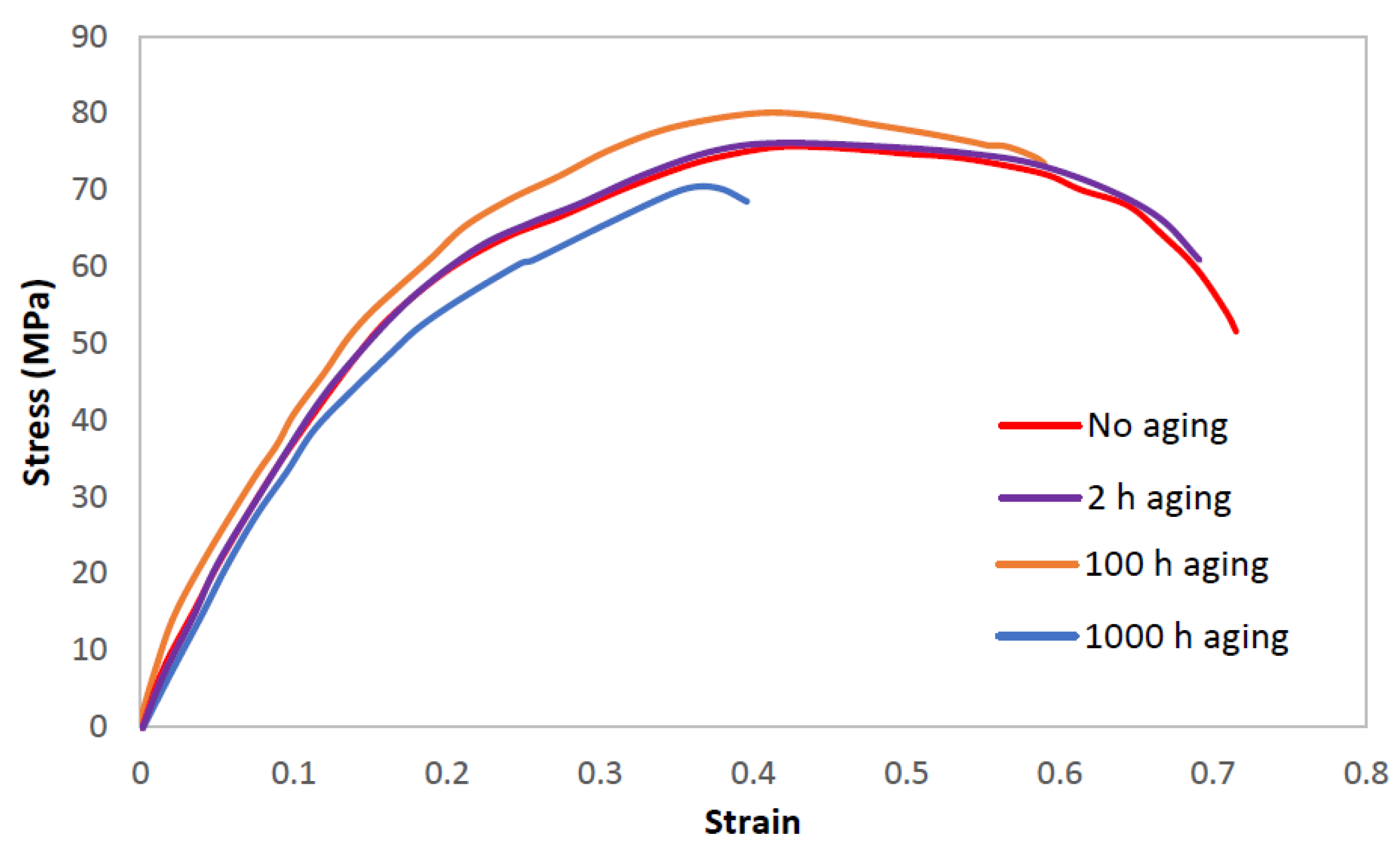
3.2. Mechanical Properties of Thermally Aged Cyclomax

Five out of ten boards were thermally aged. The thermal aging duration was different for each of the four boards, and the durations were 2, 10, 100 and 1000 h. Then, the mechanical properties of the thermally aged and non-aged samples were investigated. Ten randomly selected solder joints from each board were tested on the Instron, and the average shear stress–shear strain curve was created. Instron plots the curve directly onto a graph, and also provides data on shear strength at every 0.001 strain on Excel. The data were collected from ten replicates and averaged. These averages were then used to plot the curves for all aging conditions. The shear stress–shear strain diagram after four different aging durations, 0, 2, 100 and 1000 h, at 150 °C, is shown in Figure 11. Each shear stress–shear strain curve is an average shearing off 10 solder balls. There are several observations that can be noticed in Table 2 and Table 3: (1) With thermal aging, the modulus of elasticity (i.e., stiffness) increases with the aging duration until a certain point and then decreases and is expected to stabilize at a longer duration, as shown in Table 2. The average modulus of elasticity of the fresh sample is 444 MPa, 694 MPa for samples thermally aged for 100 h and 357 for samples thermally aged for 1000 h. The scientific explanation for the increase in the modulus of elasticity after 100 h is as follows: The presence of the Cu6Sn5 phase above the copper pad is typically low in samples that have not undergone thermal aging. Thus, moving solder over the copper pad is relatively easy. However, after aging for 100 h, irregularly shaped Cu6Sn5 forms over the copper pad, making it difficult to slide the solder over it. Finally, after heat aging for 1000 h, the Cu6Sn5 becomes a regular layer that separates the copper pad and the solder, making sliding very easy. (2) Thermal aging causes an increase in the USS for a certain period, and then the USS decreases and is expected to stabilize at a longer duration. (3) The percentage of elongation until failure declines with the aging duration. The number of different and distinct phases increases with temperature and becomes more complex due to diffusion between the copper and the weld. As a result, elongation decreases. Further, (4) toughness declines with aging. By analyzing the curve in Figure 11 at different aging durations, the USS, total energy (TE) exerted to shear off the solder joint, and ultimate energy (UE) are obtained, as shown in Table 3.
The largest force necessary to shear the solder joint divided by the area of the cross section is the USS. The USS increases with prolonged thermal aging to 100 h and then decreases at 1000 h of aging. The difference between the current USS and the original USS (i.e., 76.74 MPa) was divided by the original USS to estimate the change percentage. The increase began abruptly and then tapered down. For instance, the USS had 79.41 MPa pressure at 10 h after aging, compared to 76.74 MPa at 0 h, with an increase of about 2.67 MPa. However, the increase in the USS between the aging durations of 100 h and 10 h is only 0.04 MPa (i.e., USS of 79.41 MPa at 10 h of aging subtracted from the USS of 79.45 MPa at 100 h of aging). This result indicates that a very slight change occurred in the USS between the aging durations of 10 h and 100 h compared to the change in the USS between 0 and 10 h. However, by increasing the aging duration to 1000 h, the USS dropped to 70.09 MPa. The USS change percentage is shown in column 5 of Table 3. The USS is impacted by the reflow temperature and duration during solder joint preparation, particularly if no aging takes place. The increase and then decrease in USS with aging time can be explained by the evolution of the Cu6Sn5 layer on the Cu plate. In the aging time of 10 h and 100 h, the layer is not complete and uniform. Therefore, it is difficult to slide the solder joint over the copper pad with overlapping of the Cu6Sn5 and β-Sn phases. With the aging time increased to 1000 h, the layer becomes uniform and complete, making the sliding very smooth.
Shear toughness is defined as the ability to withstand shear force while absorbing energy without shearing a solder joint. The area under the shear stress curve is used to calculate the shear toughness. It is obvious that the toughness decreases with the aging durations until 1000 h of aging. The shear toughness is affected by the elongation and USS. The scientific explanation is as follows: Although elongation slightly decreases with aging at less than 100 h, the USS increases and has a greater effect on toughness, thereby increasing it. However, after 100 h of aging, elongation decreases significantly in addition to a decrease in USS. Considering the solder joint volume, the TE is presented in column 3 of Table 3. A considerable increase in the TE was observed for thermal aging up to 10 h. Then, a small decrease occurred at 100 h, while a big drop was noted at 1000 h of thermal aging. The percentage change in the TE is shown in column 6 of Table 3.
The UE per volume of solder joint can be estimated from the integration of the shear stress–shear strain curve. The UE increases at an early stage of aging. However, the increase is reflected in the decrease later. The maximum observed UE was 23.58 µJ after 10 h of aging. The decrease and then the increase in the UE are referred to as the strain as the USS increases and then decreases with aging duration. The percentage change in the UE is listed in column 7 of Table 3. The negative sign means that the UE is greater than it was initially.
Thermal aging at 150 °C and mechanical testing were repeated at 100 °C. The effect of thermal aging on the USS is shown in Figure 12. The increase in the USS over time is evident with the onset of thermal aging and then reverses early (less than 100 h) to decline.
According to the results, the long-term thermal aging reduces the reliability of the Cyclomax solder joints. In other words, exposing electronic devices to 150 °C is bad in the long run and this temperature should be avoided. Designers should not allow the heat resulting from the heat-emitting components to be concentrated in a specific place. Instead, these components must be distributed to distribute the heat. Moreover, the cooling liquid fan should be used if necessary. Moreover, the development of alloys that resist thermal aging is more necessary.

4. Conclusions

In this study, the effect of thermal aging over time on the mechanical properties of a Cyclomax solder joint fixed on a copper pad that simulates its presence on a real electronic PCB was investigated. The study included an examination of the microstructure of samples subjected to thermal aging for different time periods and samples not subjected to thermal aging. The following conclusions have been drawn: Three phases were observed within the Cyclomax microstructure—Ag3Sn, β-Sn and Bi—for samples not subjected to thermal aging. Small amounts of the Cu6Sn5 phase were observed at the Cu-Cyclomax contact zone. With the start of thermal aging, the Ag3Sn, β-Sn and Bi phases changed in terms of their shape and distribution, and the Cu6Sn5 phase increased to form a layer separate the copper from Cyclomax. Moreover, thermal aging caused the USS to increase over time for a certain period, and then it decreased. Thermal aging caused the modulus of elasticity to increase over time for a certain period, and then it decreased. Thermal aging caused the elongation ratio to decrease until the failure continued to decrease.
The following ideas are recommended as future actions: (1) The effect of cyclic stress (fatigue) after thermal aging on the temperature and time levels adopted in this paper can be studied. Cyclic stress during use is expected in response to fluctuating temperatures. The difference in thermal expansion mismatch between the PCB and the component creates this fatigue stress. Manufacturers target the development of fatigue-resistant SAC materials and take this point very seriously. (2) The shear stress–shear strain can be investigated after aging to 200 °C for a short time. This temperature is a little below the melting point and the behavior of the material may be different and the microstructure must be different. Although this temperature is rarely reached in normal operations, it can be reached in the event of an electric shock or short circuit. It is unlike electric shocks that last for a long time.

Author Contributions

Contributed to methodology and writing—original draft, M.M.H. and K.H.; Writing—conceptualization, review and editing, S.H. All authors have read and agreed to the published version of the manuscript.

Funding

This research received no external funding.

Institutional Review Board Statement

Not applicable.

Informed Consent Statement

Not applicable.

Data Availability Statement

The data presented in this study are available upon request from the corresponding author.

Conflicts of Interest

The authors declare no conflict of interest.

References

  1. Erinc, M.; Schreurs, P.J.G.; Geers, M.G.D. Integrated numerical–experimental analysis of interfacial fatigue fracture in SnAgCu solder joints. Int. J. Solids Struct. 2007, 44, 5680–5694. [Google Scholar] [CrossRef] [Green Version]
  2. Arfaei, B.; Tashtoush, T.; Kim, N.; Wentlent, L.; Cotts, E.; Borgesen, P. Dependence of SnAgCu solder joint properties on solder microstructure. In Proceedings of the 2011 IEEE 61st Electronic Components and Technology Conference (ECTC), Lake Buena Vista, FL, USA, 31 May–3 June 2011; pp. 125–132. [Google Scholar]
  3. Snugovsky, P.; Arrowsmith, P.; Romansky, M. Electroless Ni/immersion Au interconnects: Investigation of black pad in wire bonds and solder joints. J. Electron. Mater. 2001, 30, 1262–1270. [Google Scholar] [CrossRef]
  4. Liu, C.Y.; Chen, C.; Mal, A.K.; Tu, K.N. Direct correlation between mechanical failure and metallurgical reaction in flip chip solder joints. J. Appl. Phys. 1999, 85, 3882–3886. [Google Scholar] [CrossRef]
  5. Bani Hani, D.; Al-Athamneh, R.; Aljarrah, M.; Hamasha, S. Shear strength degradation modeling of lead-free solder joints at different isothermal aging conditions. J. Microelectron. Electron. Packag. 2021, 18, 137–144. [Google Scholar] [CrossRef]
  6. Kim, D.W.; Kong, M.; Jeong, U. Interface design for stretchable electronic devices. Adv. Sci. 2021, 8, 2004170. [Google Scholar] [CrossRef]
  7. Tummala, R.R. Electronic packaging research and education in the 21st century at PRC. In Proceedings of the 2nd 1998 IEMT/IMC Symposium (IEEE Cat. No.98EX225), Tokyo, Japan, 15–17 April 1998; pp. 185–194. [Google Scholar]
  8. Li, Y.; Wang, Z.; Li, X.; Hu, X.; Lei, M. Growth behavior of IMCs layer of the Sn–35Bi–1Ag on Cu, Ni–P/Cu and Ni–Co–P/Cu substrates during aging. J. Mater. Sci. Mater. Electron. 2019, 30, 1519–1530. [Google Scholar] [CrossRef]
  9. Jiang, N.; Zhang, L.; Liu, Z.Q.; Sun, L.; Long, W.M.; He, P.; Xiong, M.; Zhao, M. Reliability issues of lead-free solder joints in electronic devices. Sci. Technol. Adv. Mater. 2019, 20, 876–901. [Google Scholar] [CrossRef] [PubMed] [Green Version]
  10. Ma, H.; Suhling, J.C.; Lall, P.; Bozack, M.J. Reliability of the aging lead free solder joint. In Proceedings of the 56th Electronic Components and Technology Conference 2006, San Diego, CA, USA, 30 May–2 June 2006; pp. 16–20. [Google Scholar]
  11. Kang, S.K.; Choi, W.K.; Yim, M.J.; Shih, D.Y. Studies of the mechanical and electrical properties of lead-free solder joints. J. Electron. Mater. 2002, 31, 1292–1303. [Google Scholar] [CrossRef]
  12. Artaki, I.; Jackson, A.M.; Vianco, P.T. Evaluation of lead-free solder joints in electronic assemblies. J. Electron. Mater. 1994, 23, 757–764. [Google Scholar] [CrossRef]
  13. Andersson, C.; Lai, Z.; Liu, J.; Jiang, H.; Yu, Y. Comparison of isothermal mechanical fatigue properties of lead-free solder joints and bulk solders. Mater. Sci. Eng. A 2005, 394, 20–27. [Google Scholar] [CrossRef]
  14. Lee, H.T.; Lin, H.S.; Lee, C.S.; Chen, P.W. Reliability of Sn–Ag–Sb lead-free solder joints. Mater. Sci. Eng. A 2005, 407, 36–44. [Google Scholar] [CrossRef]
  15. Amalu, E.H.; Ekere, N.N. High temperature reliability of lead-free solder joints in a flip chip assembly. J. Mater. Process. Technol. 2012, 212, 471–483. [Google Scholar] [CrossRef]
  16. Swenson, D. The effects of suppressed beta tin nucleation on the microstructural evolution of lead-free solder joints. In Lead-Free Electronic Solders; Springer: Boston, MA, USA, 2006; pp. 39–54. [Google Scholar]
  17. Lee, H.; Kim, C.; Heo, C.; Kim, C.; Lee, J.-H.; Kim, Y. Effect of solder resist dissolution on the joint reliability of ENIG surface and Sn-Ag-Cu solder. Microelectron. Reliab. 2018, 87, 75–80. [Google Scholar] [CrossRef]
  18. Zhu, Y.; Li, X.; Gao, R.; Wang, C. Effect of hold time on the mechanical fatigue failure behavior of lead-free solder joint under high temperature. J. Mater. Sci. 2014, 25, 3863–3869. [Google Scholar] [CrossRef]
  19. Motalab, M.; Cai, Z.; Suhling, J.C.; Zhang, J.; Evans, J.L.; Bozack, M.J.; Lall, P. Improved predictions of lead-free solder joint reliability that include aging effects. In Proceedings of the 2012 IEEE 62nd Electronic Components and Technology Conference, San Diego, CA, USA, 29 May–1 June 2012; pp. 513–531. [Google Scholar]
  20. Mustafa, M.; Suhling, J.C.; Lall, P. Experimental determination of fatigue behavior of lead free solder joints in microelectronic packaging subjected to isothermal aging. Microelectron. Reliab. 2016, 56, 136–147. [Google Scholar] [CrossRef]
  21. George, E.; Das, D.; Osterman, M.; Pecht, M. Thermal cycling reliability of lead-free solders (SAC305 and Sn3. 5Ag) for high-temperature applications. IEEE Trans. Device Mater. Reliab. 2011, 11, 328–338. [Google Scholar] [CrossRef] [Green Version]
  22. Shnawah, D.A.; Sabri, M.F.M.; Badruddin, I.A. A review on thermal cycling and drop impact reliability of SAC solder joint in portable electronic products. Microelectron. Reliab. 2012, 52, 90–99. [Google Scholar] [CrossRef]
  23. Zhang, J.; Hai, Z.; Thirugnanasambandam, S.; Evans, J.L.; Bozack, M.J.; Zhang, Y.; Suhling, J.C. Thermal aging effects on the thermal cycling reliability of lead-free fine pitch packages. IEEE Trans. Compon. Packag. Manuf. Technol. 2013, 3, 1348–1357. [Google Scholar] [CrossRef]
  24. Liu, F.; Meng, G. Random vibration reliability of BGA lead-free solder joint. Microelectron. Reliab. 2014, 54, 226–232. [Google Scholar] [CrossRef]
  25. Che, F.X.; Pang, J.H. Study on reliability of PQFP assembly with lead free solder joints under random vibration test. Microelectron. Reliab. 2015, 55, 2769–2776. [Google Scholar] [CrossRef]
  26. Ren, F.; Nah, J.W.; Tu, K.N.; Xiong, B.; Xu, L.; Pang, J.H. Electromigration induced ductile-to-brittle transition in lead-free solder joints. Appl. Phys. Lett. 2006, 89, 141914. [Google Scholar] [CrossRef]
  27. Chen, C.; Liang, S.W. Electromigration issues in lead-free solder joints. In Lead-Free Electronic Solders; Springer: Boston, MA, USA, 2006; pp. 259–268. [Google Scholar]
  28. Yang, X.; Xiao, F.; Wang, W. Effect of Ag content on the tensile properties and microstructure of SAC305 solder alloy. J. Mater. Sci. Mater. Electron. 2018, 29, 8265–8276. [Google Scholar]
  29. Wu, H.; Yu, H.; Guo, F.; Li, S. The effect of Cu content on the mechanical properties of Sn-3.0Ag-xCu lead-free solder alloys. J. Mater. Sci. Mater. Electron. 2017, 28, 1739–1748. [Google Scholar]
  30. Wang, Y.; Zhou, L.; Li, B.; Liu, Y. Effect of Cu content on the microstructure and tensile properties of Sn-Ag-Cu lead-free solder alloys. J. Mater. Sci. Mater. Electron. 2019, 30, 4744–4754. [Google Scholar]
  31. Lin, C.C.; Hsieh, C.C.; Tsai, M.H. Effect of Ag content on the microstructure and mechanical properties of Sn-Ag-Cu solder alloys. J. Mater. Sci. Mater. Electron. 2019, 30, 5276–5286. [Google Scholar]
  32. Yi, S.; Zhou, B.; Cai, Z. Effects of Zn on the microstructure and mechanical properties of Sn-Ag-Cu based lead-free solder alloys. J. Mater. Sci. Mater. Electron. 2018, 29, 10787–10796. [Google Scholar]
  33. Guan, R.; Wang, C.; Zhang, F.; Zhou, J. Effect of Ag content on the fatigue behavior of Sn-Ag-Cu lead-free solder alloys. J. Mater. Sci. Mater. Electron. 2018, 29, 3156–3165. [Google Scholar]
  34. Zhang, Y.; Zheng, Z.; Cui, H.; Chen, Y.; Zhou, S. Effects of Ni content on the microstructure, mechanical properties and reliability of Sn-3.5Ag-0.5Cu-xNi solder alloys. J. Mater. Sci. Mater. Electron. 2019, 30, 15315–15328. [Google Scholar]
  35. Long, X.; Tang, W.; Wang, S.; He, X.; Yao, Y. Annealing effect to constitutive behavior of Sn–3.0 Ag–0.5 Cu solder. J. Mater. Sci. Mater. Electron. 2018, 29, 7177–7187. [Google Scholar] [CrossRef]
  36. Long, X.; Wang, S.; Feng, Y.; Yao, Y.; Keer, L.M. Annealing effect on residual stress of Sn-3.0 Ag-0.5 Cu solder measured by nanoindentation and constitutive experiments. Mater. Sci. Eng. A 2017, 696, 90–95. [Google Scholar] [CrossRef] [Green Version]
  37. Long, X.; Wang, S.; He, X.; Yao, Y. Annealing optimization for tin–lead eutectic solder by constitutive experiment and simulation. J. Mater. Res. 2017, 32, 3089–3099. [Google Scholar] [CrossRef]
  38. Akkara, F.J.; Zhao, C.; Athamenh, R.; Su, S.; Abueed, M.; Hamasha, S.; Suhling, J.; Lall, P. Effect of solder sphere alloys and surface finishes on the reliability of lead-free solder joints in accelerated thermal cycling. In Proceedings of the 2018 17th IEEE Intersociety Conference on Thermal and Thermomechanical Phenomena in Electronic Systems (ITherm), San Diego, CA, USA, 29 May–1 June 2018; pp. 1374–1380. [Google Scholar]
  39. Su, S.; Hamasha, K. Effect of surface finish on the shear properties of SnAgCu-based solder alloys. IEEE Trans. Compon. Packag. Manuf. Technol. 2019, 9, 1473–1485. [Google Scholar]
  40. Atiqah, A.; Jalar, A.; Bakar, M.A.; Ismail, N. Advancement of printed circuit board (PCB) surface finishes in controlling the intermetallic compound (IMC) growth in solder joints. In Recent Progress in Lead-Free Solder Technology; Springer: Cham, Switzerland, 2022; pp. 217–238. [Google Scholar]
  41. Belhadi, M.E.A.; Wentlent, L.; Al Athamneh, R.; Hamasha, S.D. Mechanical properties of SAC-Bi solder alloys with aging. In Proceedings of the 2019 SMTA International, Rosemont, IL, USA, 22–26 September 2019; pp. 22–26. [Google Scholar]
  42. Zhao, J.; Mutoh, Y.; Miyashita, Y.; Mannan, S.L. Fatigue crack-growth behavior of Sn-Ag-Cu and Sn-Ag-Cu-Bi lead-free solders. J. Electron. Mater. 2002, 31, 879–886. [Google Scholar] [CrossRef]
  43. Rizvi, M.J.; Chan, Y.C.; Bailey, C.; Lu, H.; Islam, M.N. Effect of adding 1 wt% Bi into the Sn–2.8 Ag–0.5 Cu solder alloy on the intermetallic formations with Cu-substrate during soldering and isothermal aging. J. Alloys Compd. 2006, 407, 208–214. [Google Scholar] [CrossRef]
  44. Lee, J.H.; Kumar, S.; Kim, H.J.; Lee, Y.W.; Moon, J.T. High thermo-mechanical fatigue and drop impact resistant Ni-Bi doped lead free solder. In Proceedings of the 2014 IEEE 64th Electronic Components and Technology Conference (ECTC), Orlando, FL, USA, 27–30 May 2014; pp. 712–716. [Google Scholar]
  45. Zhao, J.; Qi, L.; Wang, X.M.; Wang, L. Influence of Bi on microstructures evolution and mechanical properties in Sn–Ag–Cu lead-free solder. J. Alloys Compd. 2004, 375, 196–201. [Google Scholar] [CrossRef]
  46. Gao, L.; Xue, S.; Zhang, L.; Sheng, Z.; Ji, F.; Dai, W.; Yu, S.-l.; Zeng, G. Effect of alloying elements on properties and microstructures of SnAgCu solders. Microelectron. Eng. 2010, 87, 2025–2034. [Google Scholar] [CrossRef]
  47. Hamasha, K.; Hamasha, M.M.; Hamasha, S. Effect of the thermal aging on the mechanical properties of SAC305. Materials 2022, 15, 2816. [Google Scholar] [CrossRef]
  48. Kim, H.-J.; Lee, H.-M.; Paik, K.-W. Interfacial reactions and shear strength of SnAgCu/Cu joints with various surface finishes. J. Electron. Mater. 2012, 41, 2435–2442. [Google Scholar]
Figure 1. Test vehicle design.
Metals 13 00591 g001
Figure 2. Test board.
Metals 13 00591 g002
Figure 3. Schematic illustration of the Instron 5948 Micro-Mechanical device.
Metals 13 00591 g003
Figure 4. Schematic of shearing of the solder joint.
Metals 13 00591 g004
Figure 5. The microstructure of Cyclomax is not subject to thermal aging.
Metals 13 00591 g005
Figure 6. Microstructure of the junction area between Cyclomax and the copper pad of a sample that has not undergone thermal aging.
Metals 13 00591 g006
Figure 7. Microstructure of Cyclomax after thermal aging at 150 °C for 100 h.
Metals 13 00591 g007
Figure 8. Microstructure of the junction zone between Cyclomax and the copper pad of a sample that underwent heat aging for 100 h.
Metals 13 00591 g008
Figure 9. Microstructure of Cyclomax after thermal aging at 150 °C for 1000 h.
Metals 13 00591 g009
Figure 10. Microstructure of the junction zone between Cyclomax and the copper pad of a sample that underwent heat aging for 1000 h.
Metals 13 00591 g010
Figure 11. Average shear stress–shear strain curves of thermally aged Cylomax at 150 °C.
Metals 13 00591 g011
Figure 12. Comparison of the USS for samples thermally aged at 100 °C and 150 °C.
Metals 13 00591 g012
Table 1. EDXA analysis of phases.
EDXA
Phase
at%wt%
β-Sn95.52, 3.5% Ag, 1% Cu96.29, 3.2% Ag, 0.6 Cu
Ag3Sn78.16% Ag, 21.84% Sn76.48% Ag, 23.51% Sn
Bi98.2% Bi98.3% Bi
Cu6Sn557.22% Cu, 42.78% Ag41.7% Cu, 58.3% Ag
Cu (Cu pad)99.2% Cu98.8% Cu
Table 2. Modulus of elasticity vs. thermal aging duration.
Modulus of Elasticity (MPa)Aging Duration
4440
694100
3571000
Table 3. Extracted mechanical properties of aged and non-aged Cyclomax.
Aging
Duration
(h)
USS
(MPa)
Total Energy (µJ)Ultimate Energy
(µJ)
Shear Yield StrengthChange
% USS
Increasing % TEIncreasing
% UE
076.7429.8019.874.44
277.7838.6623.124.751.35%29.76%16.39%
1079.4140.0023.584.883.48%34.23%18.71%
10079.4538.4622.908.333.53%29.07%15.28%
100070.0916.5214.175.88–8.67%–44.57%–28.66%
Disclaimer/Publisher’s Note: The statements, opinions and data contained in all publications are solely those of the individual author(s) and contributor(s) and not of MDPI and/or the editor(s). MDPI and/or the editor(s) disclaim responsibility for any injury to people or property resulting from any ideas, methods, instructions or products referred to in the content.

