Article

Behaviour Aspects of an EB-PVD Alumina (Al2O3) Film with an Interlayer (NiCrAlY) Deposited on AISI 316L Steel Investigated in Liquid Lead

1
Institute for Nuclear Research Pitesti, POB 78, Campului Street, No. 1, 115400 Mioveni, Romania
2
Department of General Chemistry, University Politechnica of Bucharest, Splaiul Independentei Street, No. 313, 060042 Bucharest, Romania
3
Academy of Romanian Scientists, 3 Ilfov, 050094 Bucharest, Romania
4
National R&D Institute for Nonferrous and Rare Metals-IMNR, 077085 Pantelimon, Romania
*
Author to whom correspondence should be addressed.
Metals 2023, 13(3), 616; https://doi.org/10.3390/met13030616
Submission received: 20 February 2023 / Revised: 15 March 2023 / Accepted: 17 March 2023 / Published: 19 March 2023
(This article belongs to the Section Metallic Functional Materials)

Abstract

:
The use of lead as a primary coolant is one of the most attractive options for next-generation lead-cooled fast reactor systems (LFR). Despite many favourable features, liquid Pb is a harsh environment that induces many problems on metallic components. Therefore, candidate materials for LFR must be qualified, and the solutions to improve their properties must be found. This paper’s objective is to present the results obtained from the tensile tests of AISI 316L steel in liquid lead at 400 °C, 450 °C, and 500 °C, and the short-term corrosion tests performed on coated and uncoated AISI 316L steel at 550 °C. The coating was made of Al2O3 with a CrNiAlY interlayer using the electron beam-physical vapor deposition (EB-PVD) technique. Both the mechanical and corrosion tests were performed in stagnant lead saturated with oxygen. After testing, the specimens were characterised by several analyses, including scanning electron microscopy (SEM), energy-dispersive X-ray spectroscopy (EDS), optical microscopy (OM), scratching test, and Vickers micro-hardness test. The tensile test results highlight the ductile behaviour of the material, and in the case of the corrosion tests, the coatings prove to be effective in protecting the substrate from the harsh environment.

1. Introduction

To promote the concept of a safer and more secure type of reactor for future energy generation, Generation IV nuclear systems [1,2] have introduced many challenges with systems such as supercritical water-cooled reactor (SCWR), very-high-temperature reactor system (VHTR), gas-cooled fast reactor system (GFR), molten salt reactor (MSR), sodium-cooled fast reactor system (SFR), and lead-cooled fast reactor [3]. The forward-looking vision of lead-cooled fast reactors is very tightly linked to the novelty of this concept. Additionally, in the nuclear industry, this concept is requested to be advanced in parallel with a full demonstration of safety performances as a guarantee for the protection of people and the environment. To prove the effectiveness of the lead-cooled fast reactor concept that was being pursued in the European context, a demonstration reactor was envisaged in 2010. Since then, efforts have been made to develop it in a collective effort at the pan-European level. ALFRED—the Advanced Lead-cooled Fast Reactor European Demonstrator—stems from this aim: it is a research reactor that is able to demonstrate the viability of the general concept (in the short term) and support the safe and sustainable operation of the envisaged fleet of industrial systems (in the longer term) [4].
The use of lead as a primary coolant is one of the most attractive options for next-generation LFR systems [1]. Despite many favourable features, liquid Pb could induce major corrosion problems. In recent years, many investigations have been carried out to examine the mechanisms of corrosion of steels in heavy liquid metals (HLMs), such as lead, lead–bismuth eutectic (LBE), and lead–lithium eutectic (LLE) [5,6,7]. The most important phenomena include oxidation and dissolution [8,9,10,11,12,13], flow accelerated corrosion [14], grid-to-rod fretting [15], and HLM-assisted loss of mechanical properties, such as liquid metal embrittlement (LME), low-cycle fatigue [16,17], and liquid metal-assisted creep [18]. It is commonly accepted that self-passivation through controlled oxygen injection is an effective protection method for temperatures below 500 °C [19]. At higher temperatures, oxide scales are no longer protective (either due to excessive oxidation or dissolution rates), and other protection methods are required. Some of the most suitable solutions are based on the use of inhibitors [20], corrosion-resistant bulk alloys (FeCrAl steels [21], low-Ni alumina-forming-austenitic (AFA) steels [22], FeCrSi steels [23], and Mo alloys [24], among others), or surface-alloyed FeCrAl [25]. Ceramic coatings using aluminium oxide are a promising option because alumina is essentially insoluble in lead and is compatible with a wide range of thermodynamic conditions in terms of temperature and oxygen content [26].
The design and introduction of future reactor systems are strongly dependent on the choice of structural materials. These materials must withstand more demanding conditions within the Generation IV international programme. In comparison to current commercial reactors, all construction materials (particularly those for internal components and fuel cladding) of Generation IV reactors will be operated at elevated temperatures and in a corrosive environment, and they must be designed to withstand higher radiation damage due to a high fast neutron flux. Therefore, these structural materials must be tested to prove that they are qualified and even to improve their mechanical properties [27,28,29] and various coatings. The identified challenges to be analyzed in future work have been divided into five main components:
Steam generator: corrosion, LME, ratcheting, fatigue, creep–fatigue, and buckling;
Pump: erosion–corrosion, ratcheting, and fatigue;
Inner vessel: corrosion, creep–fatigue, ratcheting, and buckling;
Primary vessel: ratcheting, fatigue, creep–fatigue, and corrosion;
Fuel cladding: corrosion, fretting, and creep–fatigue.
This paper presents the results obtained after the tensile tests of AISI 316L steel in liquid lead at 400 °C, 450 °C, and 500 °C, and the short-term corrosion tests performed on coated and uncoated AISI 316L steel at 550 °C. The mechanical and corrosion tests were performed in stagnant lead saturated with oxygen (an oxygen concentration of ~10−3 wt.%) to evaluate the mechanical behaviour and to improve the corrosion resistance of steel. The temperature range of 400–550 °C was chosen because the different components of the ALFRED will be subjected to different operating temperatures. In the case of the corrosion tests, the temperature of 550 °C was chosen because it was observed that, after 500 °C, austenitic steels are more susceptible to corrosion, and the coating must protect the material at this high temperature. Thus, the minimum and maximum operating temperatures for the reactor vessel and the decay heat removal system (DHR) are expected to be between 380 and 430 °C for the inner vessel; for the steam generator and the primary pumps, the temperature range will be between 380 and 480 °C; and for the fuel cladding, it will be between 380 and 550 °C [30].
Austenitic stainless steels (ASS) are a class of materials suitable to be used in some Generation IV nuclear reactor systems because of their great corrosion resistance, high creep, and good radiation performance. Among them, 310H stainless steel (SS) is one of the promising materials for the construction of the internal components of supercritical water-cooled reactors (SCWR) [31]. It has been noticed that coating of 310H stainless steel (SS) is a way to improve its corrosion resistance [32]. In the case of LFR systems, the austenitic steel, AISI 316L/316LN, is considered for the construction of reactor and inner vessel structures and primary pumps. For steam generators and DHR, the materials that are taken into account are AISI 316L and AFA steel [30]. Promising candidate materials for fuel cladding are oxide dispersion-strengthened (ODS) steels, ferritic/martensitic (F/M) steels, and austenitic steels [33].
One of the ways to improve the corrosion resistance of existing materials in liquid lead is through the application of various deposition techniques on the surface of metallic or ceramic layers. There are several coating techniques used for advanced nuclear materials, including thermal spray (TS), chemical vapor deposition (CVD), physical vapor deposition (PVD), pulsed laser deposition (PLD), electrodeposition, sol–gel, pack cementation, cold spray, hot dipping, and thermionic vacuum arc procedure [34,35]. To obtain the desired characteristics of the coatings, these techniques can be modified or, in some cases, combined. Compared to other deposition techniques, the PVD technique can lower the deposition temperature to below 500 °C. In this manner, avoiding undesirable diffusion processes or reactions between the substrate and the coating is possible. The PVD method produces homogenous coatings. The coatings deposited using PVD are very dense, providing a layer that is thick enough. These types of coatings reduce the quantity of moisture or gas that may pass through the film. As a result, these types of coatings would be perfect for preventing material corrosion in a nuclear environment [31].
In terms of enhancing corrosion resistance in liquid lead alloys, several materials have been deposited on stainless steel surfaces: SiC, Si3N4, AlTiFe, FeAl (CVD, PVD), FeCrAlY (TS), TiN (CVD), CrN (PVD), Al (pack cementation), Al2O3 (PLD, flame spraying), Ta (electro-chemical and vapor phase), Mo (plasma spraying, flame spraying, and chemical deposition), Nb (magnetron sputtering, electron sputtering, and galvanic deposition), WC (plasma spraying), and Ti (plasma spraying). Among the materials that have shown positive behaviour are aluminium-containing coatings. These coatings develop protective and stable alumina layers through the Al selective oxidation process when exposed to Pb and LBE containing small amounts of oxygen [36].
Alumina has a high heat resistance and a high density, and the formation of Gibbs energy is very low; thus, the introduction of an Al2O3 layer on steel surface can significantly improve corrosion resistance in LBE. Generally, an alumina layer can be introduced via alloying or surface coating. For steels, overall aluminium alloying may decrease material strength, while surface aluminising can improve surface corrosion resistance without affecting the strength of the base steel. Surface coating technology needs to pay attention to two points: one is that the bonding force between the coating and the substrate should be strong enough to ensure that the coating will not easily fall off, and the second is that the formation temperature of the coating should not be too high to avoid structural coarsening and performance deterioration of the steel substrate [33].
In this work, a few specimens were coated with alumina by using the electron beam-physical vapor deposition (EB-PVD) method with a NiCrAlY interlayer to improve their adhesion and to study the improvement in their behaviour against corrosion.
MCrAlY (M = Ni, Co, or NiCo) is a typical class of oxidation-resistant coatings. It has been widely applied in turbine blades and other components for high-temperature applications. MCrAlY coatings are usually used as single overlayers or bond coatings as thermal barrier coatings (TBC) [37].
EB-PVD is one of the methods proposed to overcome some problems associated with the thermal spraying, CVD (chemical vapor deposition), and PVD methods. EB-PVD is a form of physical vapor deposition in which a target anode is bombarded with an electron beam given off by a charged tungsten filament under a high vacuum. The electron beam, which is bent by a magnetic field, causes the atoms from the target to transform into a gaseous phase. These atoms then precipitate into a solid form, coating the substrate with a thin layer of the anode material. The main advantage of the EB-PVD process is its ability to directly melt and evaporate practically any type of solid material in the form of a metal ingot or a ceramic/composite target using highly focused high-energy electron beams generated by an electron gun with a tungsten filament. The composition and microstructure of these coatings can be easily controlled, while simultaneously avoiding contamination due to the very high vacuum used. Coating adhesion can be monitored through controlled heating of the substrate during deposition. A specific aspect of EB-PVD coatings is related to their columnar microstructure, which determines the behaviour of the coatings during their service life. EB-PVD is often preferred over APS (atmospheric plasma spray) because it offers a higher growth rate and columnar coatings with a longer lifetime [38].
This paper’s aim and its novelty consist in the fabrication of EB-PVD alumina films on AISI 316L steel and a comparison of the microstructural, degradation, and mechanical aspects of the coated and uncoated specimens after being tested in liquid lead. After deposition, the coatings were analyzed using several techniques: a scratching test to assess the adhesion of the layers; an SEM analysis to examine the microstructure and thickness of the layers; and an EDS analysis to obtain information about the elemental composition. For the post-tensile and corrosion tests, the specimens were characterized by using scanning electron microscopy (SEM), optical microscopy (OM), and Vickers microhardness test.

2. Materials and Methods

The tensile and corrosion tests described in this paper used the same type of material—a commercial AISI 316L austenitic steel acquired from Outokumpu Stainless AB Company (Degerfors, Sweden). The information from the product description was as follows: AISI 316L (1.4404) coil mill edge stainless steel, (thickness × width) 3.0 × 1500 mm, ASTM A240/240M specification, heat treatment at 1070 °C, intergranular corrosion ASTM 262 Practice E: OK, and packed and marked by Outokumpu Stainless Oy [39]. The elemental composition of the 316L austenitic steel, in atomic percentages, is presented in Table 1, and the mechanical properties are listed in Table 2.

2.1. Preparation of Protective Coatings for Corrosion Tests

The rectangular specimens with dimensions of 25 mm × 12 mm × 3 mm (length × width × thickness) that were used in the corrosion tests were cut from an AISI 316L steel sheet and were provided with a hole of 4 mm diameter at one end for their mounting on the holder. Before coating, the specimens were mechanically sanded on silicon carbide papers with different granulations (P120, P240, P400, P600, and P1200), and then the substrates were ultrasonically cleaned in an isopropyl alcohol bath for 15 min and dried in air. The alumina (Al2O3) coatings with an interlayer (NiCrAlY) were deposited using the EB-PVD technique.
The coatings on the austenitic steel specimens were performed at the National R&D Institute for Nonferrous and Rare Metals (IMNR) using a TORR 5X300EB-45KW installation (Figure 1). This system has a vacuum chamber of 3 m3, in which an advanced vacuum of about 3 × 10⁻⁷ Torr can be reached.
The heating of the material to be deposited was performed with the help of 5 electron beam guns, 5 separate 10 kW (10 kV, 1000 mA) high-voltage DC power supplies, X-Y direction electron beam sweep controllers, and a deposition thickness control with a quartz crystal microbalance. The substrates for coating were fixed on a support that was rotating with a speed of 15 rot/min. In order to increase the adhesion of the coatings, the substrates were heated at about 600 °C using a set of UV lamps placed above the rotating support.
After the coatings had been made, the deposited layers were analyzed by using several techniques. A scratching test was performed to examine the adhesion of the film. The SEM analyses of the coatings and the cross sections were used to examine the microstructure and the thickness of the deposited layers, while the EDS analyses provided information about the elemental composition.

2.2. Corrosion Test in Stagnant Liquid Lead

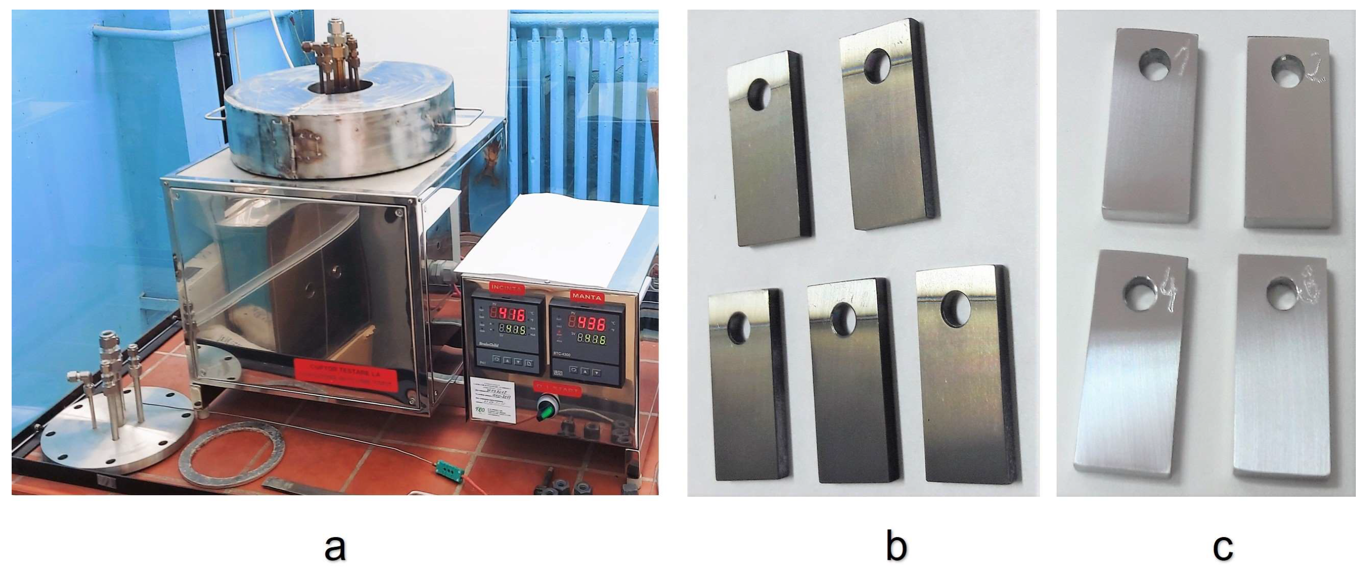
The corrosion tests were performed inside a thermally insulated stainless steel furnace opened to air, which was designed to expose steels to stagnant liquid lead (Figure 2a). The working crucible placed inside has a volume of approximately one litre.
For the corrosion tests, 5 samples of 316L stainless steel coated with alumina and NiCrAlY interlayer (Figure 2b), and 4 specimens of uncoated 316L steel (Figure 2c) were used. Before the corrosion tests, the uncoated samples were also mechanically sanded on the same abrasive paper grades as the coated ones. The testing conditions were stagnant liquid lead at a temperature of 550 °C, with an oxygen concentration of 10−3 wt.%. The corrosion tests were carried out for 500 h and 1000 h.

2.3. Testing Facility for Mechanical Tests in Liquid Lead

The mechanical tests in liquid lead at high temperatures were performed in a testing facility (LILETIN—LIquid LEad Testing INstallation) designed and built in RATEN ICN to study the effects of Pb on the mechanical properties of structural materials in static conditions. The LILETIN facility allows the performance of tensile tests in a liquid metal crucible configuration, with temperatures of up to 500 °C in static conditions and oxygen saturation [40]. The schematic view of the LILETIN facility, which was set up in the Instron tensile system, is shown in Figure 3. It has the following operational parameters and features: a maximum temperature of 500 °C, a Pb volume of 0.9 L, and a strain rate controller. The liquid metal temperature is monitored by a thermocouple inserted in the crucible.
The tensile tests were carried out on the uncoated flat 316L steel tensile specimens (Figure 4) in liquid lead at 400 °C, 450 °C, and 500 °C, with oxygen saturation. These test temperatures were chosen because certain components that operate at a minimum temperature in the range of 380–550 °C could still be validated. The samples were made in accordance with the American standards for testing in the field (ASTM E8), having a total length of 40 mm, a length of 12.5 mm for the calibrated area, a width of 2 mm for the calibrated area, and a thickness of 2 mm. Before testing, the samples were visually examined and dimensionally checked, and then they were degreased and polished on sandpaper up to 1200 grit.
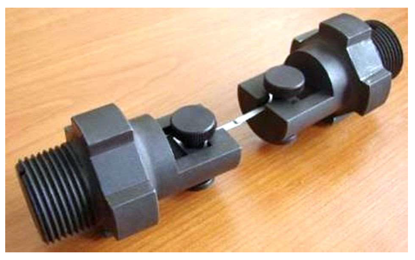
For this type of sample, 2 pull grips were adapted, as shown in Figure 5.
To perform the tensile tests, a constant strain rate of 5 × 10⁻⁵ s−1 was applied. This strain rate was chosen as an optimum while considering both practical and physical considerations. In order to carry out the SEM analysis after the tensile tests in liquid lead, the fracture surface was cleaned to remove residual lead by using a solution of acetic acid, hydrogen peroxide, and ethanol.

2.4. Characterisation Methods and Devices

The coatings were analyzed by several techniques. A scratching test, using a NANOVEA M1 Scratch Tester (Irvine, CA, USA), was performed to examine the adhesion of the film. The SEM analyses on the surface and in the cross section were used to examine the microstructure and the thickness of the thin film, and the EDS analysis provided information about the elemental composition of the deposited layers. In this case, an FEI QUANTA 250 electronic microscope (Eindhoven, The Netherlands) was used with EDS, LFD, and BSE detectors.
After the corrosion tests, the samples were analysed by optical microscopy using an Olympus GX71M light microscope (Tokyo, Japan). To evaluate the material corrosion and the coating integrity, small pieces were cut from the samples, embedded in conductive cupric resin, and polished on SiC paper with increasing grits of up to P4000. The Vickers micro-hardness (MHV0.1) modifications were determined by using an OPL SOPELEM tester (Dijon, France) in an automatic cycle.
The SEM analyses after the tensile tests were performed with a TESCAN VEGA LMU electronic microscope with EDS and BSE detectors (Brno, Czech Republic).

3. Results and Discussion

3.1. Coating Layer Analysis

The scratching test was performed on the 316L coated steel at different pressing forces. This force increased from 1 N to 20 N with a loading speed of 5 N/s over a distance of 5 mm. After the maximum force was reached, the penetration depth of the indenter into the material was approximately 90 µm, and no exfoliations occurred during the test.
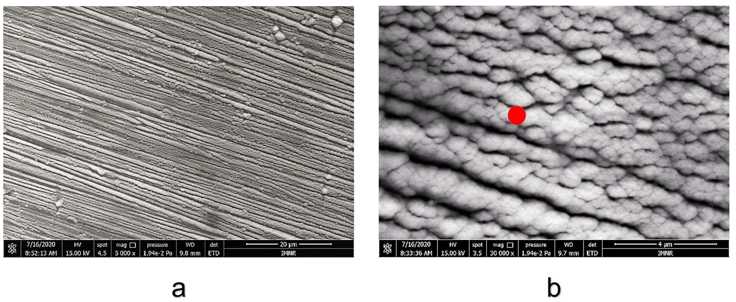
Figure 6 presents the SEM micrographs of the coatings. It can be seen that there is a continuous deposition of the nano-porous columnar alumina layer with the grains being preferentially oriented in a certain axial direction.
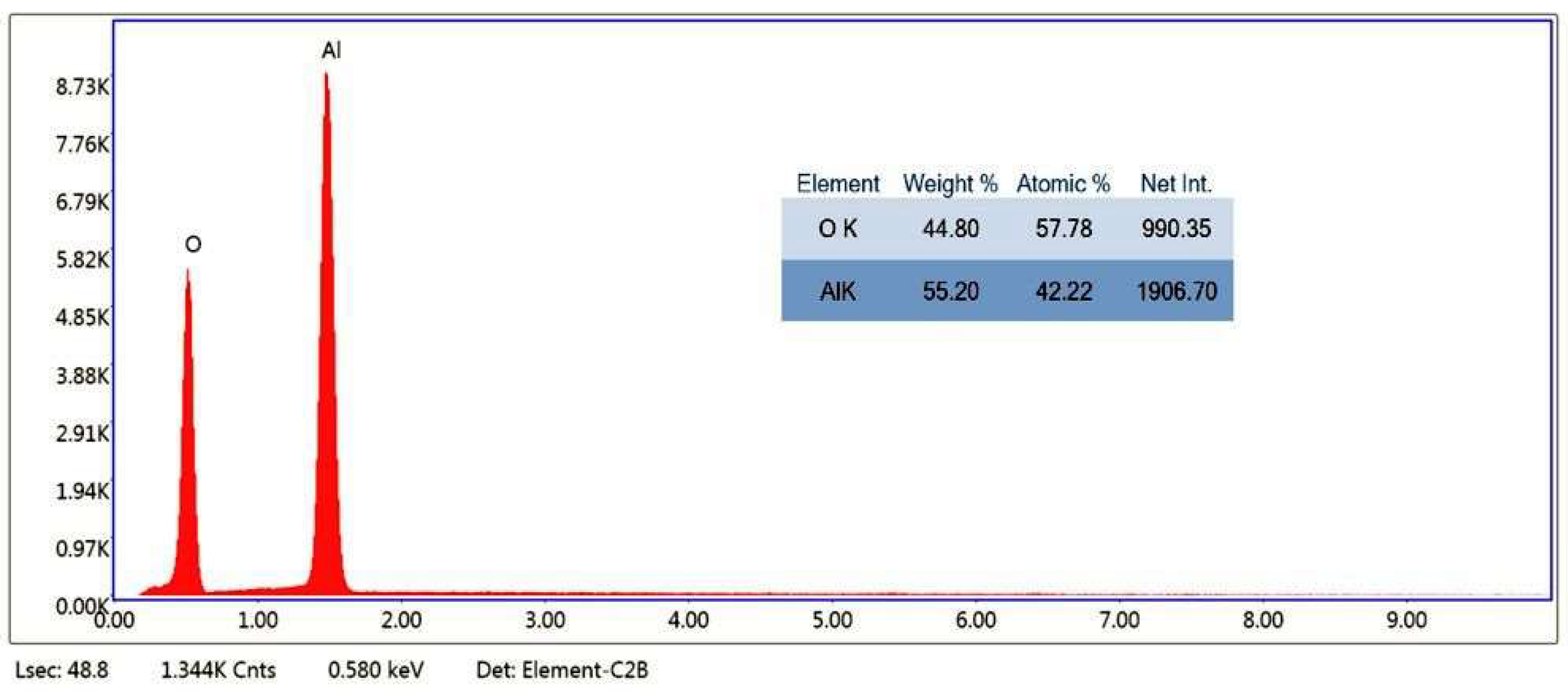
The results of the EDS performed at one red point (shown in Figure 6b) on the surface of the coated specimen confirm that the top layer is alumina because it contains only aluminium and oxygen (Figure 7). However, a very small oxygen deficiency is observed. The average oxygen concentration in aluminium oxide particles may depend on the specific surface area S, the average radius R of the powder particles used for the coatings, and their method of preparation [41].
An in-line EDS analysis was also performed in the cross section, starting from the substrate area and passing through the coating (Figure 8a). Here, both deposited layers (NiCrAlY/Al2O3) are highlighted. In Figure 8b, it can be seen that in the substrate zone, there is a very high concentration of iron (yellow line). As the analysis progresses through the interlayer, the iron concentration decreases and an increase in the nickel, chromium, and aluminium contents is observed. The NiCrAlY buffer layer presents a morphology with two alternating layers in which one has a higher chromium content, and the other has more nickel. However, since the concentration of yttrium is very low, it could not be determined by the EDS analysis, but from the certificate of the powder used, it should be 0.9 wt.%. In the second layer, the previous lines decrease, while the lines specific to aluminium and oxygen (brown and blue lines) show an increase in their content.
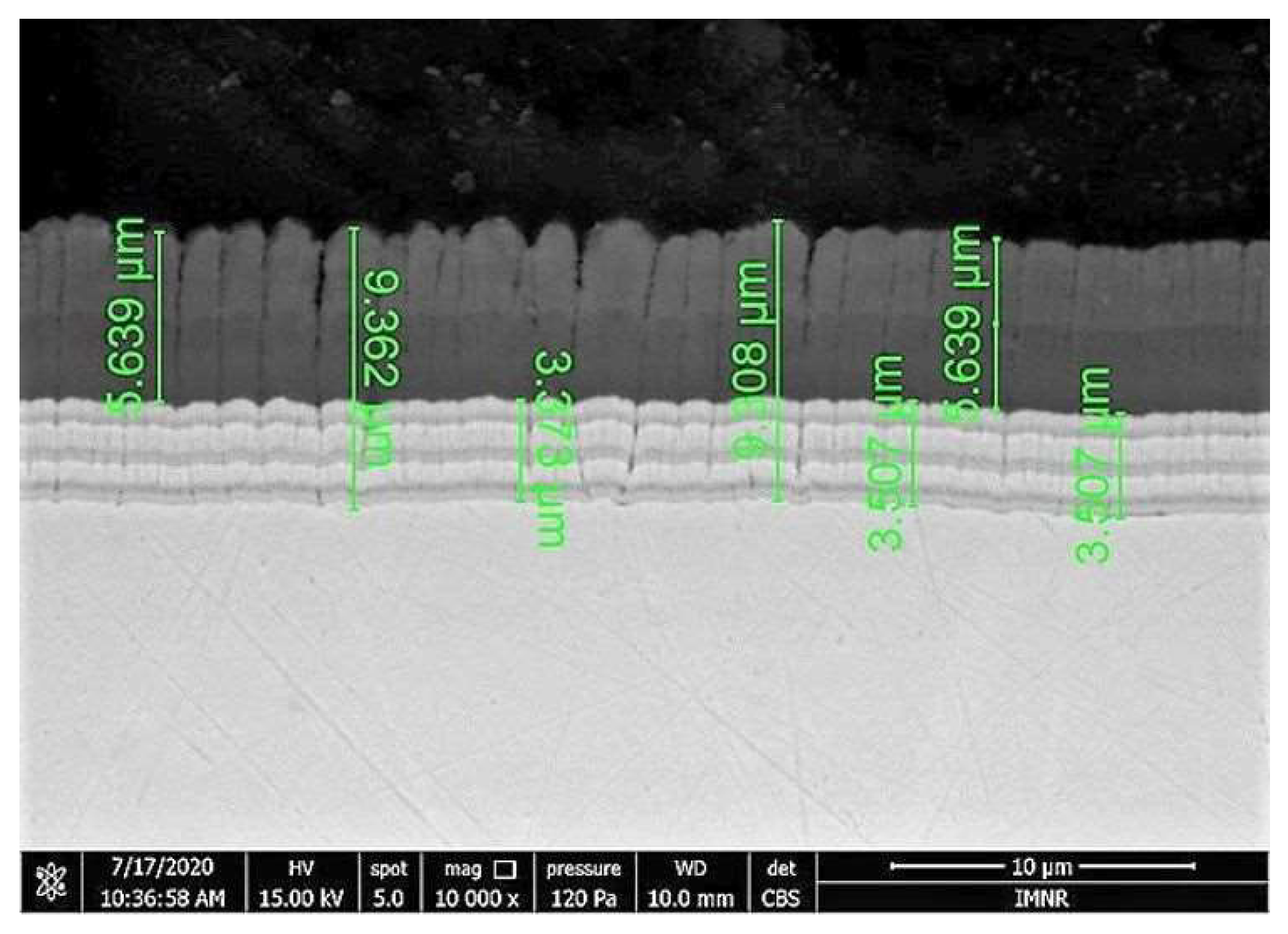
The coating thicknesses were measured using the SEM technique (Figure 9). Thus, it was determined that the thickness is about 3 µm for the NiCrAlY layer and approximately 5–6 µm for the Al2O3 layer.

3.2. Corrosion Test

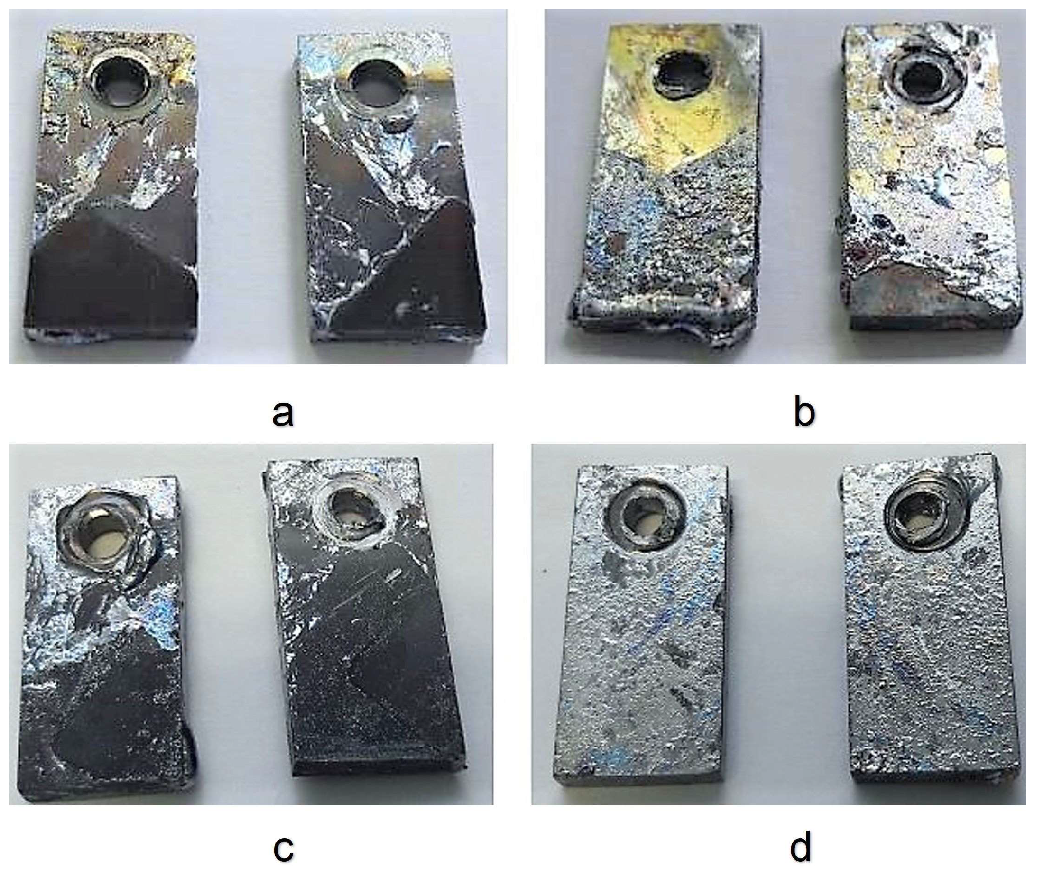
After removing the samples from the melted Pb, the surface of the tested samples remains covered with solidified lead in certain areas (Figure 10). From the visual appearance, it is possible to see that the bare samples are covered with a large amount of solidified lead (metallic grey color) compared to the coated samples. However, when the specimen was cut in the cross section, the lead might have detached.
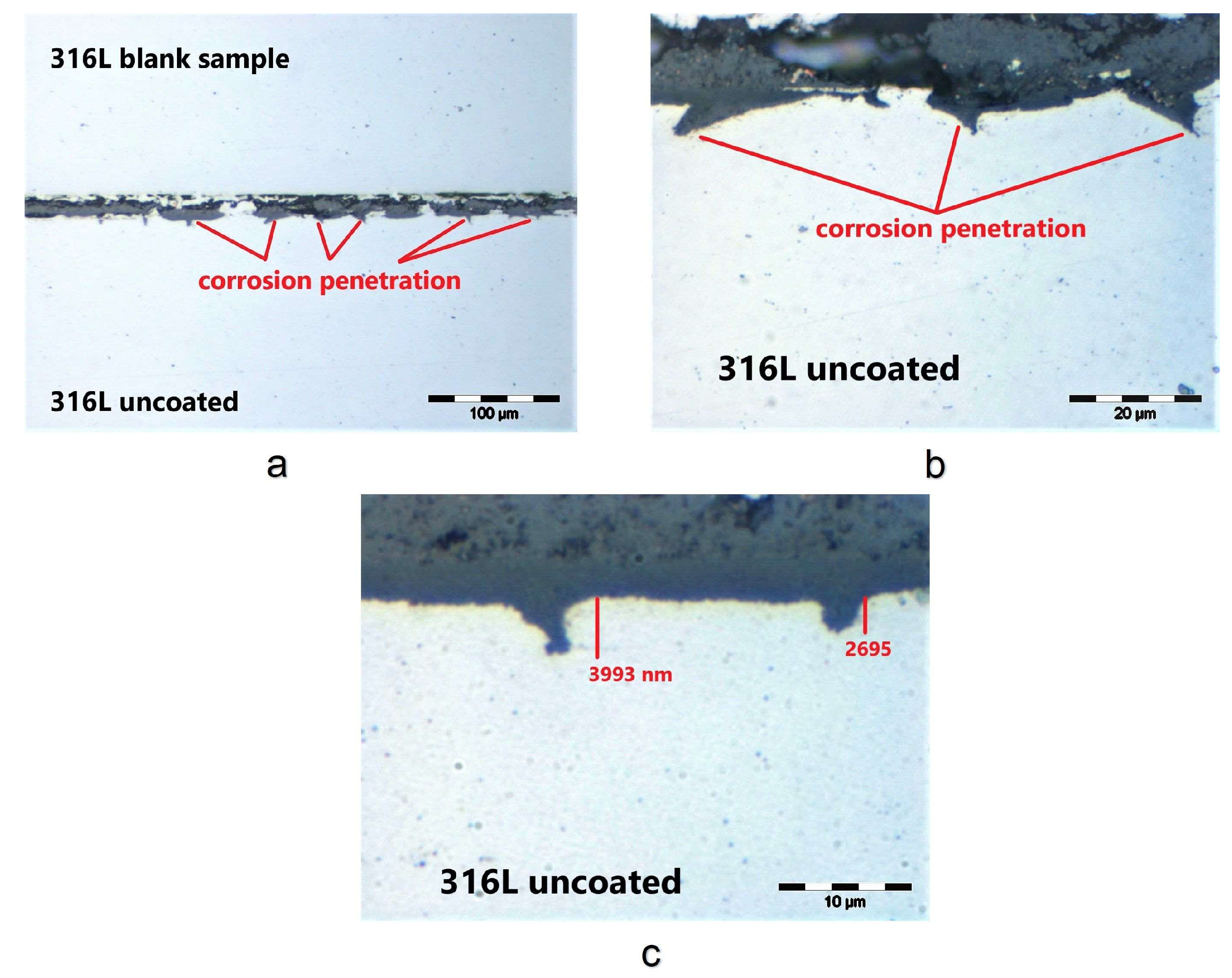
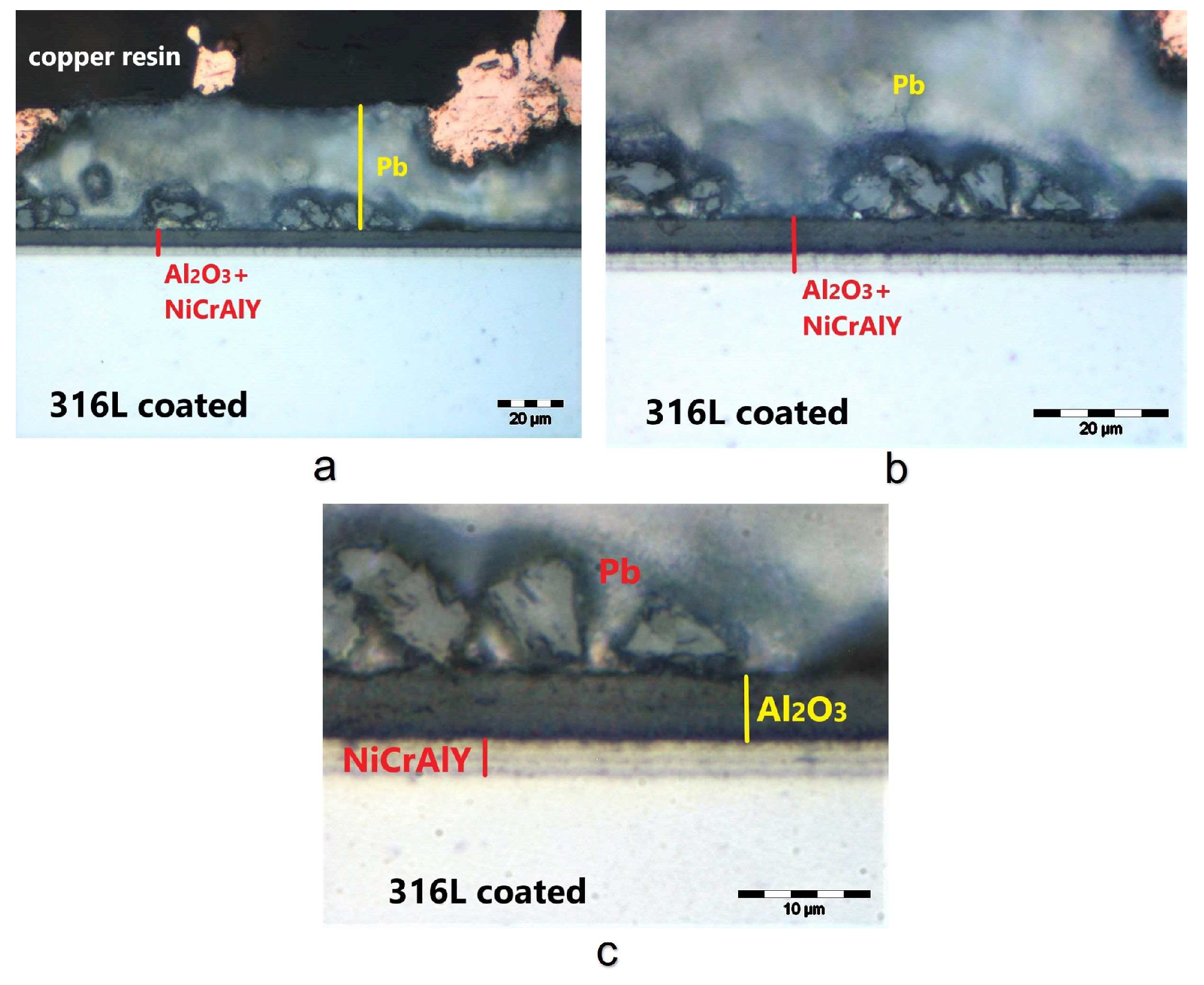
The OM was used to analyze the specimen surface, the thickness of the oxide layer formed, and the coating integrity after the exposure. For this analysis, one of the uncoated specimens was examined in the cross section. The images in Figure 11 show that lead has not penetrated the steel substrate, so the structural integrity of the material is not affected after 500 h of exposure.
However, after 1000 h of exposure to liquid lead, the uncoated specimen presents evidence of corrosion in the matrix, as shown in Figure 12. The penetration depths measured at several locations are between 2.7 µm and 7.3 µm. It seems most likely to be an internal oxidation process. Additionally, other studies [42,43,44] have shown the formation of an internal oxide layer and a more porous external layer after longer periods of exposure of some ODS, austenitic, and martensitic steels to molten lead.
C. Cionea et al. investigated oxide scale formation on 316L stainless steel exposed to static LBE with an oxygen concentration of 10−5 wt.% at a temperature of 700 °C. Their results showed the presence of a 35 μm duplex layer, which was identified as being comprised of a magnetite Fe3O4 phase and a chromite FeCr2O4 phase [45].
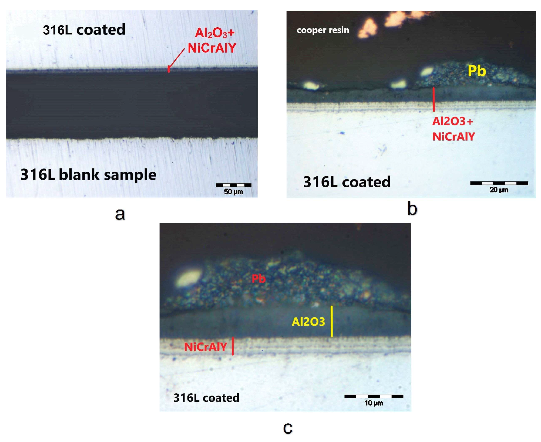
In the case of the coated 316L specimen after 500 h of testing in liquid lead at 550 °C, the coating is still intact, adherent, and compact (Figure 13). The coating thickness measured with OM at ×2000 magnification, after the molten lead test, is almost 3.0 µm for the interlayer and 5.2 µm for the alumina layer.
Even after 1000 h of exposure to molten lead, the 316L coated specimen still presents a continuous, intact, adherent, and compact film, as shown in Figure 14. In this case, the thicknesses measured after the test are 3.1 µm for the NiCrAlY buffer layer and 5.2 µm for the Al2O3 layer. Moreover, each film thickness is unaltered after the molten lead test and, therefore, no coating erosion has occurred.
Additionally, the results of some studies have shown that NiCrAlY/Al2O3 double-layer coating by air plasma spraying has a much better cyclic oxidation resistance in air at 850 °C than the base alloy. The parabolic rate constant of oxidation is 2.62 × 10⁻¹² g2·cm−4·s−1, and the coating presents a good adhesion during the cyclic oxidisation treatment [46].
Previous studies examining the tribocorrosion behaviour of two coatings, NiCoCrAlYTa and NiCrAlY, deposited on 316L steel and 718 alloys showed that these kinds of coatings presented an extremely dense structural characteristic and good tribological performance in NaOH and HCl solutions. In the extreme conditions, with an acid solution, the corrosion current density (Icorr) was 7.866 × 10⁻⁵ A/cm2 for the NiCoCrAlYTa coating and 3.356 × 10⁻⁶ A/cm2 for the NiCrAlY coating [47,48]. Corrosion property is influenced by corrosion rate, which is directly proportional to Icorr value according to Faraday’s law [49]. Therefore, a high value for Icorr indicates a high corrosion rate. In another case involving a surface modification process with dual-layer NiCrAlY (90 µm) and mullite (163 µm), the potentiodynamic test in 3.5% NaCl solution revealed an Icorr value of 1.59 × 10⁻⁶ A/cm2. This value was much smaller than the Icorr values of the substrate or of the sample with only mullite coating. The two-layer sample exhibited better corrosion resistance due to the existence of a dense corrosion-resistant NiCrAlY coat and a stronger bonding strength [50].
The corrosion resistance of a T91 steel coated with alumina by magnetron sputtering PVD was also studied by E. Miorin in stagnant liquid Pb at 550 °C for 1200 h. The results showed the growth of a non-adherent and wrinkled oxide layer on the uncoated steel, which had a variable macroscopic morphology on different surface zones and appeared detached from the bulk in several places. In contrast, the alumina coating of the T91 steel appeared intact, compact, and adherent to the substrate, with a uniform thickness [51].
To investigate how the hardness of the material changed after the test in molten lead, six micro-indentations were made in the cross sections of each specimen near the specimen surface. This test used a load of 100 gf in order to obtain indents larger than 20 µm in the diagonal direction. For the control sample, the Vickers microhardness was 199 HV0.1. In the case of the samples tested for 500 h, there was a decrease in microhardness by 18 units for the 316L coated specimen (181 HV0.1) and by 23 units for the uncoated specimen. After 1000 h of testing in liquid lead, the coated sample suffered a microhardness loss of 22 units and the uncoated sample lost 27 units. These decreases in microhardness could have appeared after the thermal treatments due to the elimination of residual stresses in the steel.
Furthermore, because the concentration of oxygen in the lead coolant is very important, and it is foreseen that the ALFRED will be operated at a low oxygen content (10−6–10−8 wt.%), the next research works will focus on this aspect, and an oxygen control system will be implemented in the corrosion test facilities using a gas injection system with an argon and hydrogen mixture.

3.3. Tensile Behaviour of 316L Steel in a Liquid Lead Environment

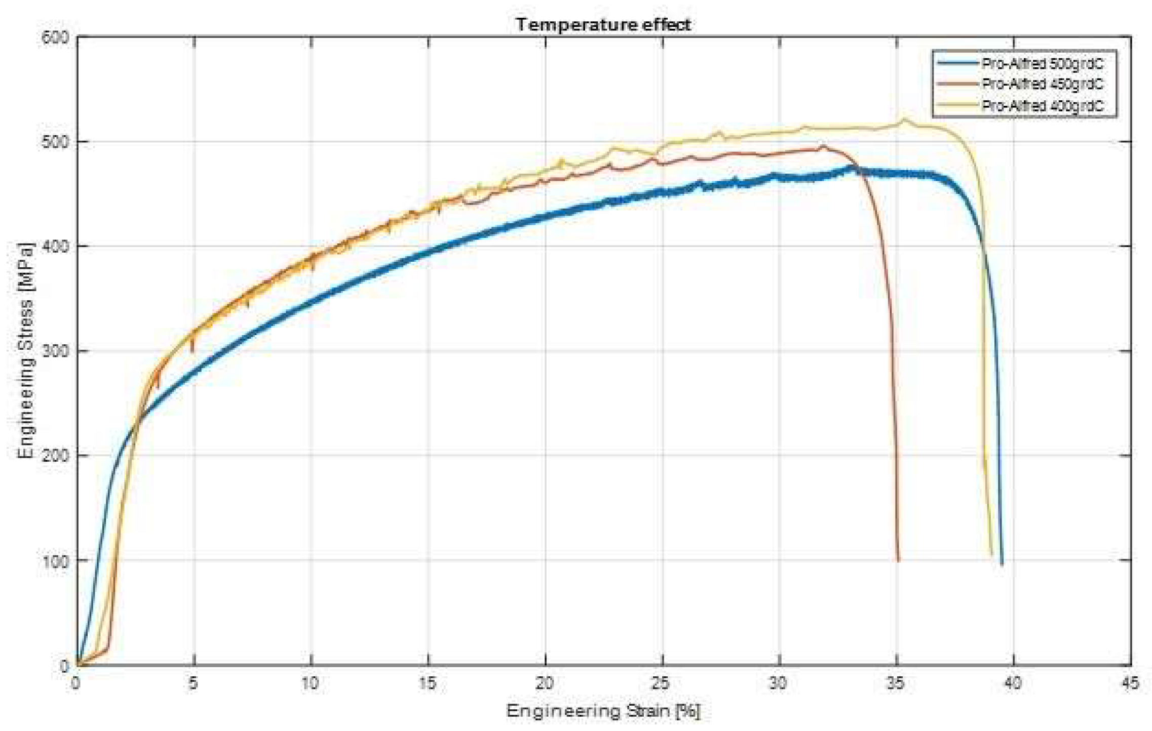
The tensile tests were carried out at three different temperatures of interest, namely 400 °C, 450 °C, and 500 °C. These tests were performed in accordance with the ASTM E8 standards [52] on the flat samples obtained from 316L austenitic steel. The obtained results are presented in Table 3 and Figure 15.
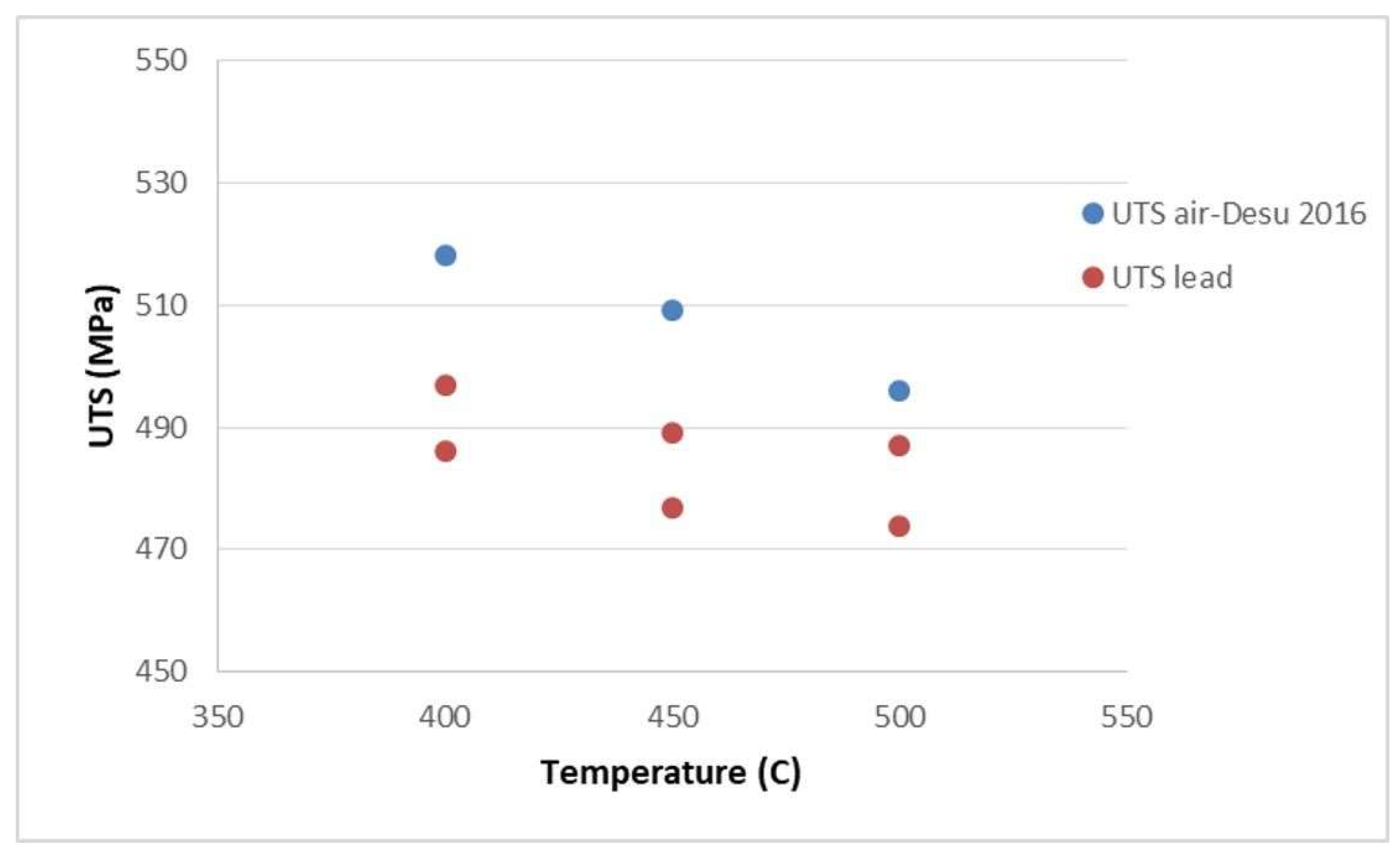
The tensile curves presented in Figure 15 highlight the ductile behaviour of the material. It can be observed that as the test temperature increases, the tensile strength (UTS—ultimate tensile strength) decreases. Additionally, when compared to the literature data [53,54,55], a decrease in the UTS values in relation to the tensile tests in air is observed (Figure 16). This decrease in UTS values could be an effect of the liquid lead environment on the mechanical properties of the material.
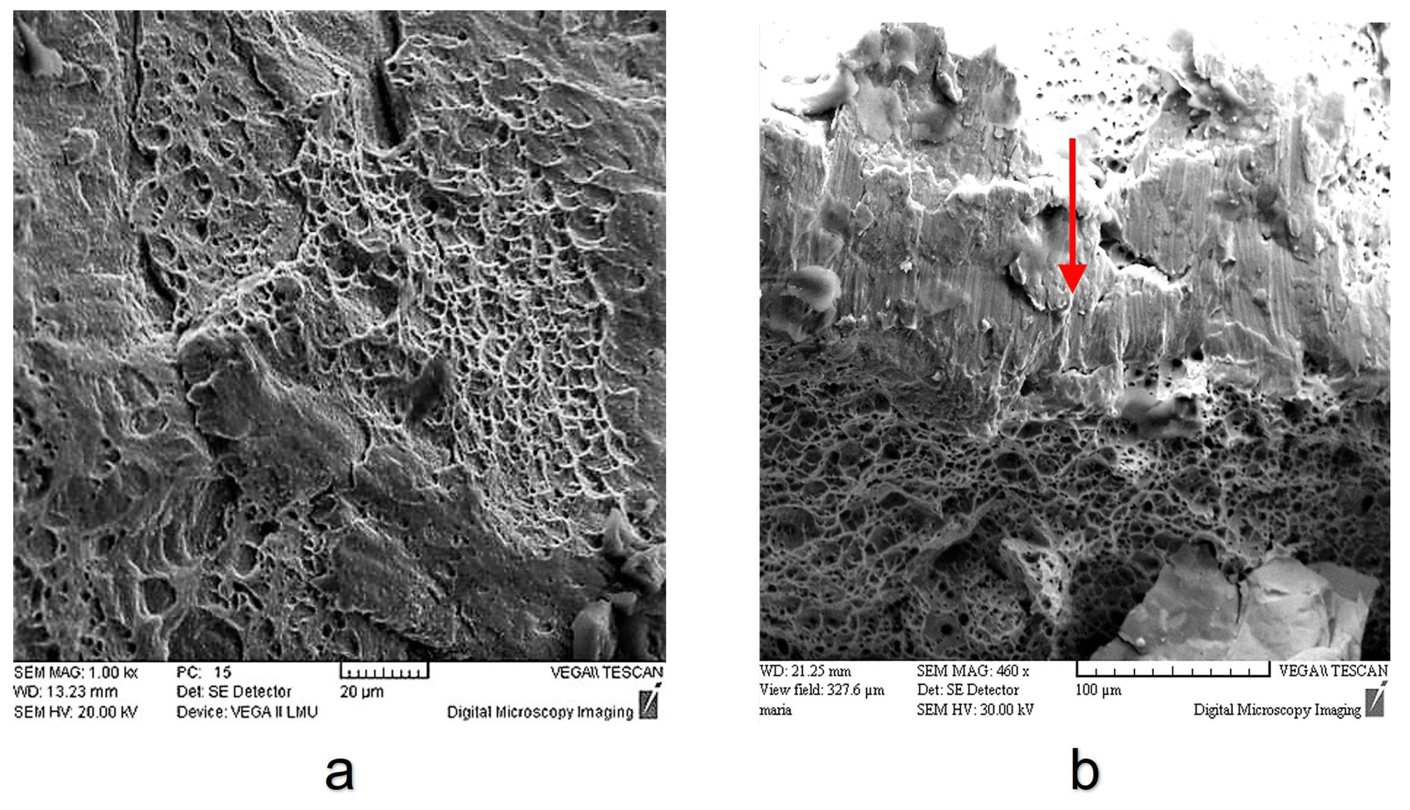
However, it is obvious there is a need to perform more tests in a liquid lead environment to establish clear mechanical properties and temperature dependence, as well as to compare with air tests to evaluate the influence of liquid lead. The SEM images of the fractured surface of the samples tested at 400 °C (Figure 17), 450 °C (Figure 18a), and 500 °C (Figure 18b) reveal that crack starts to grow from the surface of the specimens and then moves inwards (from brittle to ductile—red arrow) because of the interaction with molten lead. An analysis of the SEM images shows a mixed fracture surface that presents both ductile fracture zones and brittle fracture zones. Brittle fracture is an effect of the interaction between the 316L steel and the liquid lead, which leads to a degradation of material properties through embrittlement.

4. Conclusions

Alumina (Al2O3) coating with an interlayer (NiCrAlY) was deposited using the EB-PVD technique, aiming at the protection of 316L steel from lead corrosion. Before the corrosion tests, the coating was characterized by scratching, SEM, and EDS analyses, which confirmed an adherent and compact layer with the specified chemical composition, and a thickness of ~3 µm for the interlayer and almost 5 µm for the alumina layer. Following the corrosion tests, the uncoated specimen presented an internal oxidation process after 1000 h in liquid lead at 550 °C. In comparison, all coated specimens had good corrosion resistance and presented a continuous, intact, adherent, and compact double-layer film. The coating thickness after the test in liquid lead was similar to the thickness before the test, with 3 µm for the interlayer and 5.2 µm for the alumina layer.
The decrease in the microhardness of the tested specimens, compared to the control sample, could be attributed to the elimination of residual stresses after the corrosion test at a temperature of 550 °C.
The tensile tests at a constant strain rate of 5 × 10⁻⁵ s−1 highlighted the effects of temperature and the liquid lead environment on the 316L steel. Thus, a decrease in breaking strength was observed as the temperature increased. When compared to the other tests performed in air, the UTS values for the specimens tested in lead showed a slight decrease. The SEM images revealed that crack started to grow from the surface of the specimens and then moved inwards (from brittle to ductile).

Author Contributions

Conceptualization, D.P., A.N., F.G., I.D. and M.C.; methodology, D.P., A.N. and M.C.; software, F.G. and M.C.; validation, F.G.; formal analysis, D.P. and A.N.; investigation, F.G.; data curation, D.P., A.N. and M.C.; writing—original draft preparation, D.P., A.N. and I.D.; writing—review and editing, I.D. and F.G.; visualization, D.P., A.N. and I.D.; supervision, I.D. and F.G. All authors have read and agreed to the published version of the manuscript.

Funding

This research received no external funding.

Institutional Review Board Statement

Not applicable.

Informed Consent Statement

Not applicable.

Data Availability Statement

The data presented in this study are available upon request.

Conflicts of Interest

The authors declare no conflict of interest.

References

  1. Petrescu, D.; Fulger, M.; Golgovici, F.; Demetrescu, I. Addressing some issues encountered in liquid lead corrosion tests of candidate materials for future nuclear reactors. UPB Sci. Bull. Ser. B 2022, 84, 89–97. [Google Scholar]
  2. Corwin, W.R.U.S. Generation IV Reactor Integrated Materials Technology Program. Nucl. Eng. Technol. 2006, 38, 591–618. [Google Scholar]
  3. Yvon, P. Structural Materials for Generation IV Nuclear Reactors 2016; Woodhead Publishing Series in Energy; Woodhead Publishing: Sawston, UK, 2016; ISBN 9780081009062. [Google Scholar]
  4. Frogheri, M.; Alemberti, A.; Mansani, L. The Advanced Lead Fast Reactor European Demonstrator (ALFRED). In Proceedings of the 15th International Topical Meeting on Nuclear Reactor Thermal—Hydraulics, Pisa, Italy, 12–17 May 2013. [Google Scholar]
  5. Zhang, J. A review of steel corrosion by liquid lead and lead-bismuth. Corros. Sci. 2009, 51, 1207–1227. [Google Scholar] [CrossRef]
  6. Gorynin, I.V.; Karzov, G.P.; Markov, V.G. Structural materials for atomic reactors with liquid metal heat-transfer agents in the form of lead or lead-Bismuth alloy. Met. Sci. Heat Treat. 1999, 41, 384–388. [Google Scholar] [CrossRef]
  7. Chen, X.; Yuan, Q.; Madigan, B. Long-corrosion behavior of martensitic steel welds in static molten Pb-17Li alloy at 550 °C. Corros. Sci. 2015, 96, 178–185. [Google Scholar] [CrossRef]
  8. Wang, J.; Lu, S.; Rong, L. Effect of silicon on the oxidation resistance of 9 wt.% Cr heat resistance steels in 550 °C lead-bismuth eutectic. Corros. Sci. 2016, 111, 13–25. [Google Scholar] [CrossRef]
  9. Martinelli, L.; Balbaud-Celerier, F.; Terlain, A.; Delpech, S. Oxidation mechanism of a Fe-9Cr-1Mo steel by liquid Pb-Bi eutectic alloy. Corros. Sci. 2008, 50, 2523–2536. [Google Scholar] [CrossRef]
  10. Hosemann, P.; Dickerson, R.; Dickerson, P. Transmission electron microscopy (TEM) on oxide layers formed on D9 stainless steel in lead bismuth eutectic (LBE). Corros. Sci. 2013, 66, 196–202. [Google Scholar] [CrossRef]
  11. Muller, G.; Heinzel, A.; Konys, J.; Schumacher, G.; Weisenburg, A. Behavior of steels in flowing liquid PbBi eutectic alloy at 420–600 °C after 4000–7200 h. J. Nucl. Mater. 2004, 335, 163–168. [Google Scholar] [CrossRef]
  12. Shroer, C.; Wedemeyer, O.; Novotny, J. Selective leaching of nickel and chromium from Type 316 austenitic steel in oxygen-containing lead-bismuth eutectic (LBE). Corros. Sci. 2014, 84, 113–124. [Google Scholar] [CrossRef] [Green Version]
  13. Yamaki, E.; Ginestar, K.; Martinelli, L. Dissolution mechanism of 316L in lead-bismuth eutectic at 500 °C. Corros. Sci. 2011, 53, 3075–3085. [Google Scholar] [CrossRef]
  14. Kondo, M.; Takahashi, M.; Suzuki, T.; Ishikawa, K.; Hata, K.; Qiu, S.Z.; Sekimoto, H. Metallurgical study on erosion and corrosion behaviors of steels exposed to liquid lead-bismuth flow. J. Nucl. Mater. 2005, 343, 349–359. [Google Scholar] [CrossRef]
  15. Del Giacco, M.; Weisenburger, A.; Müller, G. Fretting corrosion of steels for lead alloys cooled ADS. J. Nucl. Mater. 2014, 450, 225–236. [Google Scholar] [CrossRef]
  16. Van den Bosch, J.; Coen, G.; Hosemann, P.; Maloy, S.A. On the LME susceptibility of Si enriched steels. J. Nucl. Mater. 2012, 429, 105–112. [Google Scholar] [CrossRef]
  17. Gong, X.; Marmy, P.; Volodin, A.; Amin-Ahmadi, B.; Qin, L.; Schryvers, D.; Gavrilov, S.; Stergar, E.; Verlinden, B.; Wevers, M.; et al. Multiscale investigationof quasibrittle fracture characteristics in a 9Cr-1Mo ferritic-martensitic steelembrittled by liquid lead-bismuth under low cycle fatigue. Corros. Sci. 2016, 102, 137–152. [Google Scholar] [CrossRef]
  18. Jianu, A.; Müller, G.; Weisenburger, A.; Fazio, C.; Markov, V.G.; Kashtanov, A.D. Creep-to-rupture tests of T91 steel in flowing Pb-Bi eutectic melt at 550 °C. J. Nucl. Mater. 2009, 394, 102–108. [Google Scholar] [CrossRef]
  19. Weisenburger, A.; Mansani, L.; Schumacher, G.; Müller, G. Oxygen for protective oxide scale formation on pins and structural material surfaces in lead-alloy cooled reactors. Nucl. Eng. Des. 2014, 273, 584–594. [Google Scholar] [CrossRef]
  20. Asher, R.C.; Davies, D.; Beetham, S.A. Some observations on the compatibility of structural materials with molten lead. Corros. Sci. 1977, 17, 545–557. [Google Scholar] [CrossRef]
  21. Ejenstam, J.; Halvarsson, M.; Weidow, J.; Jönsson, B.; Szakalos, P. Oxidation studies of Fe10CrAl-RE alloys exposed to Pb AT 550 °C for 10000 h. J. Nucl. Mater. 2013, 443, 161–170. [Google Scholar] [CrossRef]
  22. Ejenstam, J.; Szakalos, P. Long term corrosion resistance of alumina forming austenitic stainless steels in liquid lead. J. Nucl. Mater. 2015, 461, 164–170. [Google Scholar] [CrossRef]
  23. Short, M.P.; Ballinger, R.G.; Hänninen, H.E. Corrosion resistance of alloys F91 and Fe-12Cr-2Si in lead-bismuth eutectic up to 715 °C. J. Nucl. Mater. 2013, 434, 259–281. [Google Scholar] [CrossRef]
  24. Rivai, A.K.; Takahashi, M. Corrosion investigations of Al-Fe-coated steels, high Cr steels, refractory metals and ceramics in lead alloys at 700 °C. J. Nucl. Mater. 2010, 398, 146–152. [Google Scholar] [CrossRef]
  25. Fetzer, R.; Weisenburger, A.; Jianu, A.; Müller, G. Oxide scale formation of modified FeCrAl coatings exposed to liquid lead. Corros. Sci. 2012, 55, 213–218. [Google Scholar] [CrossRef]
  26. García Ferré, F.; Mairov, A.; Iadiciccoa, D.; Vanazzi, M.; Bassini, S. Corrosion and radiation resistant nanoceramic coatings for lead fast reactors. Corros. Sci. 2017, 124, 80–92. [Google Scholar] [CrossRef]
  27. Kashkarov, E.; Afornu, B.; Sidelev, D.; Krinitcyn, M.; Gouws, V.; Lider, A. Recent Advances in Protective Coatings for Accident Tolerant Zr-Based Fuel Claddings. Coatings 2021, 11, 557. [Google Scholar] [CrossRef]
  28. Gavrilov, S.; Coen, G.; Van den Bosch, J. Mechanical Properties of Structural Materials in HLM. In Proceedings of the SEARCH Meeting, Pisa, Italy, 27 June 2012. [Google Scholar]
  29. Gómez-Briceño, D. Guideline Document for HLM Technology, Deliverable N. 25 VELLA; Ciemat: Madrid, Spain, 2009. [Google Scholar]
  30. Lorusso, P.; Bassini, S.; Del Nevo, A. GEN-IV LFR Development: Status & Perspectives. Prog. Nucl. Energy 2018, 105, 318–331. [Google Scholar] [CrossRef]
  31. Tudose, A.E.; Gologovici, F.; Anghel, A.; Manuela, F.; Demetrescu, I. Corrosion Testing of CrNx coated 310 H Stainless Steel under Simulated Supercritical Water Conditions. Materials 2022, 15, 5489. [Google Scholar] [CrossRef]
  32. Tudose, A.E.; Demetrescu, I.; Golgovici, F.; Fulger, M. Oxidation behavior of an austenitic steel (Fe, Cr and Ni), the 310 H, in a deaerated supercritical water static system. Metals 2021, 11, 571. [Google Scholar] [CrossRef]
  33. Wang, H.; Xiaoi, J.; Wang, H.; Chen, Y.; Yin, X. Corrosion Behavior and Surface Treatment of Cladding Materials Used in High-Temperature Lead-Bismuth Eutectic Alloy: A Review. Coatings 2021, 11, 364. [Google Scholar] [CrossRef]
  34. Kashkarov, E.; Sidelev, D.; Rombaeva, M.; Syrtanov, M.; Bleykher, G. Chromium coatings deposited by cooled and hot target magnetron sputtering for accident tolerant nuclear fuel claddings. Surf. Coat. Technol. 2020, 389, 125618. [Google Scholar] [CrossRef]
  35. Diniasi, D.; Golgovici, F.; Anghel, A.; Fulger, M.; Surdu-Bob, C.C.; Demetrescu, I. Corrosion Behavior of Chromium Coated Zy-4 Cladding under CANDU Primary Circuit Conditions. Coatings 2021, 11, 1417. [Google Scholar] [CrossRef]
  36. Nuclear Energy Agency. Corrosion protection in lead and lead-bismuth eutectic at elevated temperatures. In Handbook on Lead-Bismuth Eutectic Alloy and Lead Properties, Materials Compatibility, Thermal-Hydraulics and Technologies; OECD, Nuclear Science: Paris, France, 2015; pp. 631–632. [Google Scholar]
  37. Gong, X.; Chen, R.; Wang, Y. Microstructure and Oxidation Behavior of NiCoCrAlY Coating with Different Sm2O3 Concentration on TiAl Alloy. Front. Mater. 2021, 8, 710431. [Google Scholar] [CrossRef]
  38. Piticescu, R.; Urbina, M.; Rinaldi, A. Development of Novel Material Systems and Coatings for Extreme Environments: A Brief Overview. J. Miner. Met. Mater. Soc. 2019, 71, 683–690. [Google Scholar] [CrossRef]
  39. Inspection Certificate No. 783863/08.08.2017; Product 316L Steel; Saritas Celik Sanayi: Istanbul, Turkey, 2017.
  40. Ionescu, V.; Radu, V.; Nițu, A.; Ion, A.; Olaru, V.; Stoica, L. The Study of Mechanical Properties for Generation IV Candidate Materials by Tensile Tests; Internal Report RATEN ICN: Pitesti, Romania, 2018. [Google Scholar]
  41. Vykhodets, V.; Jarvis, E.; Kurennykh, T.; Beketov, I. Extreme deviations from stoichiometry in alumina nanopowders. Surf. Sci. 2014, 630, 182–186. [Google Scholar] [CrossRef]
  42. Di Gabriele, F.; Amore, S.; Scaiola, C. Corrosion behavior of 12Cr-ODS steel in molten lead. Nucl. Eng. Des. 2014, 280, 69–75. [Google Scholar] [CrossRef]
  43. Navas, M.; Hernandez, R. Compatibility of Structural Materials with Lead and Lead Bismuth Eutectic for CSP Applications. AIP Conf. Proc. 2018, 2033, 230009. [Google Scholar] [CrossRef]
  44. Vogt, J.-B.; Serre, I.P. A Review of the Surface Modifications for Corrosion Mitigation of Steels in Lead and LBE. Coatings 2021, 11, 53. [Google Scholar] [CrossRef]
  45. Cionea, C.; Abad, M.D.; Aussat, Y.; Frazer, D. Oxide scale formation on 316L and FeCrAl steels exposed to oxygen controlled static LBE at temperatures up to 800 °C. Sol. Energy Mater. Sol. Cells. 2016, 144, 235–246. [Google Scholar] [CrossRef] [Green Version]
  46. Anghel, M.E.; Marcu, M.; Banu, A.; Atkinson, I. Microstructure and oxidation resistance of a NiCrAlY/Al2O3-sprayed coating on Ti-19Al-10Nb-V alloy. Ceram. Int. 2016, 42, 12148–12155. [Google Scholar] [CrossRef]
  47. Li, B.; Gao, Y.; Li, C.; Guo, H. Tribocorrosion Properties of NiCrAlY Coating in Different Corrosive Environments. Materials 2020, 13, 1864. [Google Scholar] [CrossRef]
  48. Liu, X.; An, Y.; Li, S.; Zhao, X.; Hou, G. An assessment of tribological performance on NiCoCrAlYTa coating under corrosive environments. Tribol. Int. 2017, 115, 35–44. [Google Scholar] [CrossRef]
  49. Mythreyi, O.; Raja, A.; Nagesha, B. Corrosion Study of Selective Laser Melted IN718 Alloy upon Post Heat Treatment and Shot Peening. Metals 2020, 10, 1562. [Google Scholar] [CrossRef]
  50. Jam, A.; Derakhshandeh, S.; Pakseresht, A. Evaluation of microstructure and electrochemical behavior of dual-layer NiCrAlY/mullite plasma sprayed coating on high silicon cast iron alloy. Ceram. Int. 2017, 43, 14146–14155. [Google Scholar] [CrossRef]
  51. Miorin, E.; Montagner, F.; Zin, V.; Giuranno, D. Al rich PVD protective coatings: A promising approach to prevent T91 steel corrosion in stagnant liquid lead. Surf. Coat. Technol. 2019, 377, 124890. [Google Scholar] [CrossRef]
  52. ASTM E8/E8M-21; Standard Test Methods for Tension Testing of Metallic Materials. ASTM International: West Conshohocken, PA, USA, 2022.
  53. Cooper, A.; Brayshaw, W. Tensile Fracture Behavior of 316L Austenitic Stainless Steel Manufactured by Hot Isostatic Pressing. Metall. Mater. Trans. 2018, 49, 1579–1591. [Google Scholar] [CrossRef] [Green Version]
  54. Langdon, G.S.; Schleyer, G.K. Unusual strain rate sensitive behavior of AISI 316L austenitic stainless steel. J. Strain Anal. Eng. Des. 2004, 39, 71–86. [Google Scholar] [CrossRef]
  55. Desu, R.K.; Krishnamurthy, H.N.; Balu, A.; Gupta, A.K.; Singh, S.K. Mechanical properties of Austenitic Stainless Steel 304L and 316L at elevated temperatures. J. Mater. Res. Technol. 2016, 5, 13–20. [Google Scholar] [CrossRef] [Green Version]
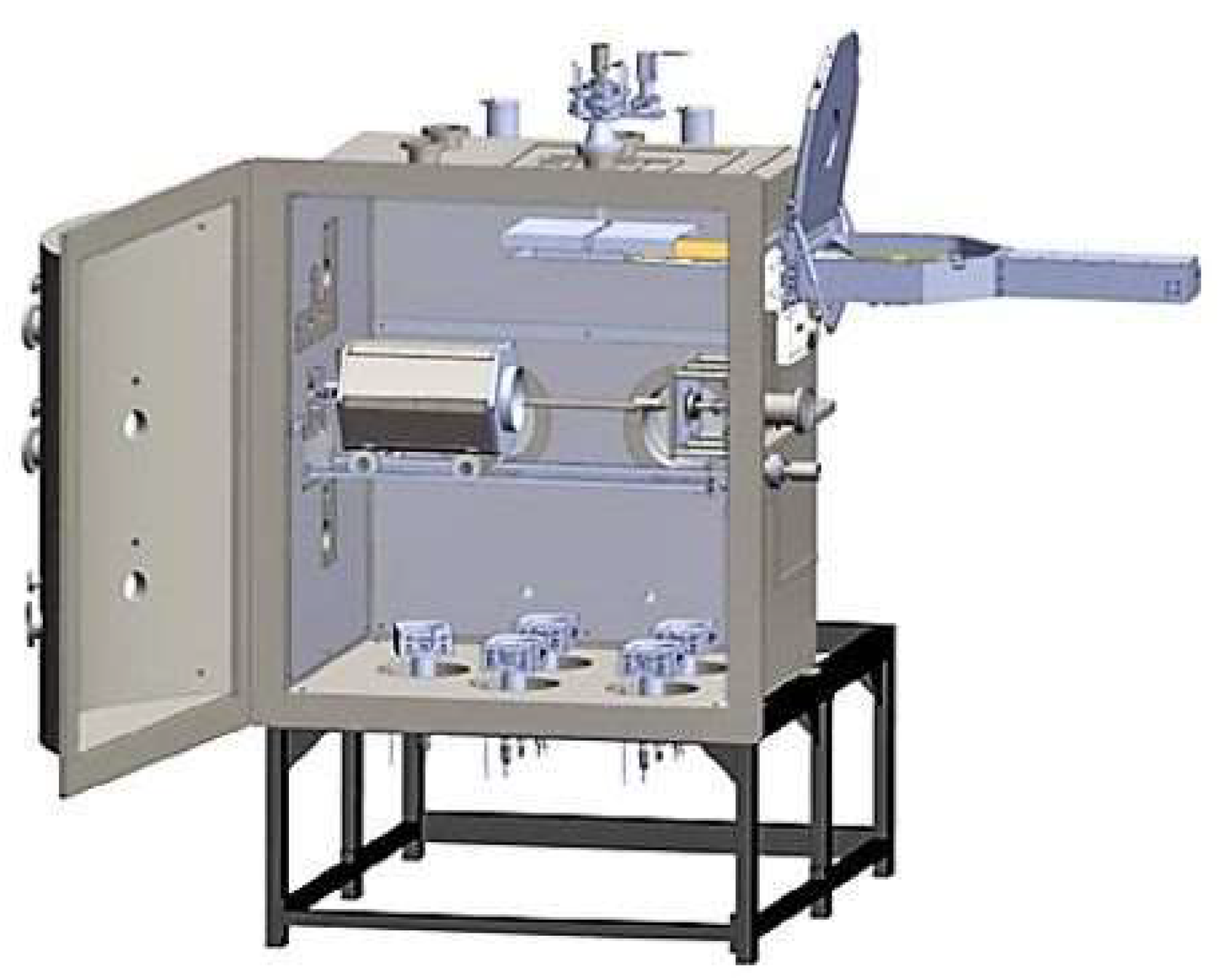
Figure 1. TORR 5X300EB-45kW electron flux deposition system.
Metals 13 00616 g001
Figure 2. Installation system for corrosion tests in liquid lead: (a) coated (b) and uncoated (c) 316L samples before the corrosion tests.
Metals 13 00616 g002
Figure 3. LILETIN facility: 1—furnace, 2—liquid lead vessel, 3—specimen fixing assembly, and 4—rod.
Metals 13 00616 g003
Figure 4. Small-sized flat tensile specimen.
Metals 13 00616 g004
Figure 5. Specimen fixing assembly.
Metals 13 00616 g005
Figure 6. SEM image depicting the surface of the alumina-deposited layer at different magnifications: 5000× (a) and 30,000× (b).
Metals 13 00616 g006
Figure 7. The result of the EDS analysis.
Metals 13 00616 g007
Figure 8. Cross-sectional analyses of the coated specimen: SEM (a) and EDS (b).
Metals 13 00616 g008
Figure 9. SEM images of the layer thicknesses before the corrosion tests.
Metals 13 00616 g009
Figure 10. Optical images of the 316L stainless steel samples: coated (a,c) and uncoated (b,d) after 500 h (a,b) and 1000 h (c,d) of testing in liquid lead.
Metals 13 00616 g010
Figure 11. Cross section of a AISI 316L uncoated specimen after being tested for 500 h in liquid lead at different magnifications: 200× (a), 500× (b), and 1000× (c).
Metals 13 00616 g011
Figure 12. Cross section of an AISI 316L uncoated specimen after being tested for 1000 h in liquid lead at different magnifications: 200× (a), 1000× (b), and 2000× (c).
Metals 13 00616 g012
Figure 13. Cross section of the AISI 316L coated samples after being tested for 500 h in liquid lead at different magnifications: 240× (a), 1000× (b), and 2000× (c).
Metals 13 00616 g013
Figure 14. Cross section of the AISI 316L coated specimen after being tested for 1000 h in liquid lead at different magnifications: 500× (a), 1000× (b), and 2000× (c).
Metals 13 00616 g014
Figure 15. Effect of testing temperature on engineering stress.
Metals 13 00616 g015
Figure 16. Effect of liquid lead on engineering stress.
Metals 13 00616 g016
Figure 17. SEM micrographs of the fracture surface of 316L steel at 400 °C at 1000× magnification, showing different areas in (a,b).
Metals 13 00616 g017
Figure 18. SEM micrographs of the fracture surface of 316L steel at 450 °C (a) and 500 °C (b).
Metals 13 00616 g018
Table 1. Chemical composition of the 316L austenitic steel.
Elements%
FeCCrNiMoMnSiPS
Bal.0.0217.110.12.030.90.470.033<0.001
Table 2. Mechanical properties of the 316L austenitic steel (20 °C).
Yield strengthRp0.2 = 306 MPa
Tensile strengthRm = 604 MPa
ElongationA5 = 59%
Hardness166 HBW
Table 3. UTS values on the flat specimens.
No. Specimen CodTesting Temperature [°C]UTS [MPa]
1.Pro-Alfred S1500487
2.Pro-Alfred S2500474
3.Pro-Alfred S3450489
4.Pro-Alfred S4450477
5.Pro-Alfred S5400497
6.Pro-Alfred S6400486
Disclaimer/Publisher’s Note: The statements, opinions and data contained in all publications are solely those of the individual author(s) and contributor(s) and not of MDPI and/or the editor(s). MDPI and/or the editor(s) disclaim responsibility for any injury to people or property resulting from any ideas, methods, instructions or products referred to in the content.