Article

Binder Jet Additive Manufacturing Process and Material Characterization for High Temperature Heat Exchangers Used in Concentrated Solar Power Applications

GE Research, Niskayuna, NY 12309, USA
*
Author to whom correspondence should be addressed.
Metals 2023, 13(3), 617; https://doi.org/10.3390/met13030617
Submission received: 4 January 2023 / Revised: 7 February 2023 / Accepted: 22 February 2023 / Published: 19 March 2023
(This article belongs to the Section Additive Manufacturing)

Abstract

:
The U.S. Department of Energy’s (DOE) Sunshot 2030 initiative has a goal of reducing the cost of concentrating solar power (CSP) to 5 cents per kWh for baseload power plants. One of the potential pathways to this goal includes a reduction in the cost of the supercritical CO2 (sCO2) power block to 0.9 cents per kWh. Recuperators—high and low temperatures, used in the sCO2 power cycle, contribute to >50% of the cost of the power cycle. This work studies the feasibility towards a ≥10% cost reduction for High Temperature Recuperators (HTR) used in the sCO2 power cycle. One way to address the cost reduction is by leveraging low-cost additive manufacturing, specifically, Binder Jet Additive Manufacturing (BJAM) to 3D print HTRs at scale. This study focuses on the development of a BJAM process towards 3D printing HTR cores using Stainless Steel alloy 316L (SS316L). To evaluate the suitability of the BJ process towards the HTR, high level specifications of the application are translated to materials capability requirements. Subsequently, at-temperature materials testing is conducted on as-printed and sintered additively manufactured coupons. Data from the coupons are compared against cast and wrought SS316L data obtained from the literature. Results show that the tensile properties from the BJ process compare well against cast properties. Furthermore, a baseline analysis of creep testing data is established for the BJ process, and insights are drawn from the results towards future improvements of the process.

1. Introduction

The U.S. Department of Energy’s Solar Energy Technology Office (SETO) 2030 performance and cost targets for supercritical carbon dioxide (sCO2) power cycles applied to concentrated solar power (CSP) have a target of $900 per kWe from the 2018 cost of $1200 per kWe. This study targets one component in the power cycle– recuperators. These devices are typically counter-flow heat exchangers which exchange heat between cold and hot flows. Successful results from this program applied to two recuperating heat exchangers in the sCO2 power block are estimated to contribute $175/kWe to power cycle cost reduction. In turn, this enables a pathway to low-cost concentrated solar energy at <5c/kWh by 2030. The details of this assessment have been previously published in [1].
Heat exchangers (HX) used in sCO2 power cycles [2,3] require high effectiveness and reliability at a low cost. The HXs are subjected to constantly cycling high temperature (~590 °C) and pressure conditions (>90 bar). Historically, high-temperature and pressure applications use shell and tube HXs, which are often heavier and expensive for sCO2 applications, especially to meet DOE’s cost target of 5c/kWh. The most common HX type used in sCO2 cycles are printed circuit heat exchangers (PCHEs) with small flow passages etched in plates, which are then stacked, and the stack is diffusion bonded into a monolithic structure. In PCHEs, thermal mechanical strain leading to metal fatigue is the primary failure mechanism in the sCO2 application, along with failure at the welded headers. To address this challenge, PCHEs are designed with thick plates made of SS316L sufficient to handle the strain, and hence result in heavier and expensive HXs, although lower than shell and tube HXs. Other materials such as Inconel 718 and Nickel-based super alloys have been demonstrated for higher temperatures but are more expensive.
This work leverages the additive design and manufacturing of a heat exchanger core that has a high heat transfer capability while maintaining the required pressure drop constraints at the required temperatures. The heat exchanger core geometry consists of a novel trifurcating unit cell design, which is illustrated in Figure 1. In a trifurcating unit cell, a flow stream (hot or cold), divides in to three separate flow streams (shown as yellow arrows) that feed into a neighboring unit cell where the flow stream merges with two other streams from other neighboring cells (merging flow streams represented with purple arrow in a plane of unit cells extending into the screen). A three-dimensional representation of trifurcating fluid streams within a single unit cell, hot and cold, is also shown in Figure 1a. Such a unit cell architecture leads to a high overall heat transfer co-efficient (UA > 2 × 10⁶ W/K), which is obtained by leveraging small channel diameters (1–2 mm) and a trifurcating design, which resets the thermal boundary layer as the channels divide and converge every 1–3 diameters in length. High heat transfer results in a lower surface area requirement, thus resulting in lower overall HX volume and mass. The HX design also results in a lower pressure drop due to a massively parallel flow unit cell architecture. The heat exchanger design utilizes curved unit cells that can withstand higher pressure relative to rectangular planar cells, thereby reducing the wall thickness requirement, leading to lower mass. As a result of these design features enabled by additive manufacturing, the resulting heat exchanger is >50% lower in volume and mass, which in-turn results in >50% lower cost [1].
In this design, several unit cell cores are arranged together to form modules. The idea behind the module is to create an integral unit for 3D printing in a single build. Furthermore, a modular HX arrangement, where each unit core consists of such trifurcating unit cell architectures, that are additively fabricated using BJAM, have the potential to result in up to 50% lower cost due to the >50% lower mass and volume of HXs [1,4] relative to conventional printed circuit heat exchangers (PCHE) operating at temperatures >550 °C. The efficient core enables a smaller heat exchanger, less material, and a lower cost. The work also includes a modular heat exchanger design that utilizes the heat exchanger core, enabling the assembly of large-scale additive heat exchangers that are both economical and robust to the transient behavior of the sCO2 power block system.
The actual design of the HTR is not within the scope of this discussion. The work presented here focuses on the additive process itself, including metal powder selection, characterization, and mechanical assessment of 3D printed material’s tensile strength, and creep properties.

1.1. Additive Manufacturing

Additive manufacturing (AM) has attracted considerable attention in recent years since it enables the manufacturing of complex parts at a significantly reduced cost and lead time compared to conventional manufacturing processes [5]. Several AM processes exist for manufacturing a variety of materials—plastics, metals, composites, and ceramics. However, the number of metallic alloys that can be manufactured by AM remains limited [6]. A part of this reason lies in the specific applications of parts manufactured using AM. This article is focused on BJAM, which is a type of additive manufacturing process that offers direct printing without molds, minimal tooling, and flexibility of design compared to conventional manufacturing methods.
Over the past three decades, a variety of materials have been printed using Binder Jet [7]. One of the earliest uses of Binder Jet printing was in 3D printing of sand-casting molds. In this process, a binding agent such as a foundry-grade resin is used for the selective deposition based on computer-aided design (CAD) to produce molds [8]. Direct printing of sand molds via BJAM does not require tooling and skillful labor needed for the conventional manufacturing methods [9]. This in turn leads to reduced lead time and cost of manufacturing complex sand molds.
In a related process, the injection molding (IM) process leverages a binder to bond metal powder together. This process includes the injection of the molded material into a mold, followed by de-binding, heat treatment, and a cool-down step. For certain parts, IM is preferable and cost-effective relative to conventional manufacturing since it can be configured to manufacture parts without the direct labor once it is set up [10]. On the other hand, IM requires significant time and labor costs for the preparation of tooling, which in turn makes it not suited for small batches of parts or complex geometries [11].

1.2. Binder Jet Additive Manufacturing

Binder Jet metal printing combines the binder jetting approach of sand 3D printing with the binder technology of metal injection molding to create 3D printed metal parts via powder bed AM. In contrast to additive modalities such as directed energy deposition (DED) and powder bed fusion (PBF), Binder Jet has the potential for higher scalability due to its higher printing speed. Moreover, the print performance of the binder jet can be accelerated by increasing the number of nozzles, which directly correlates to the time of printing per layer [12]. In contrast, the printing speed is highly constrained in DED and PBF, since the scan speed directly affects the print quality and resolution. For example, very high scan speeds might induce insufficient deposition of the part. In this case, higher print speed can be driven by increasing the number of lasers. Another attractive aspect of BJAM is that the sintering process typically involves controlled heating rates, and long soak times, which cause less severe thermal gradients, in comparison to DED and PBF processes, and less probability for parts to suffer from thermal-strain-induced cracks.
For metal additive manufacturing using BJAM, the focus has been on the development of Fe-based (SS316, 17-4PH), Cu-based [13], and W-based alloys, along with some effort on Ni-based superalloys (IN625, IN718) [14]. Past studies have typically focused on powder chemistry, powder rheology, sintering conditions, and thermal-mechanical properties of the sintered parts.

2. Materials and Methods

2.1. Binder Jet AM Process

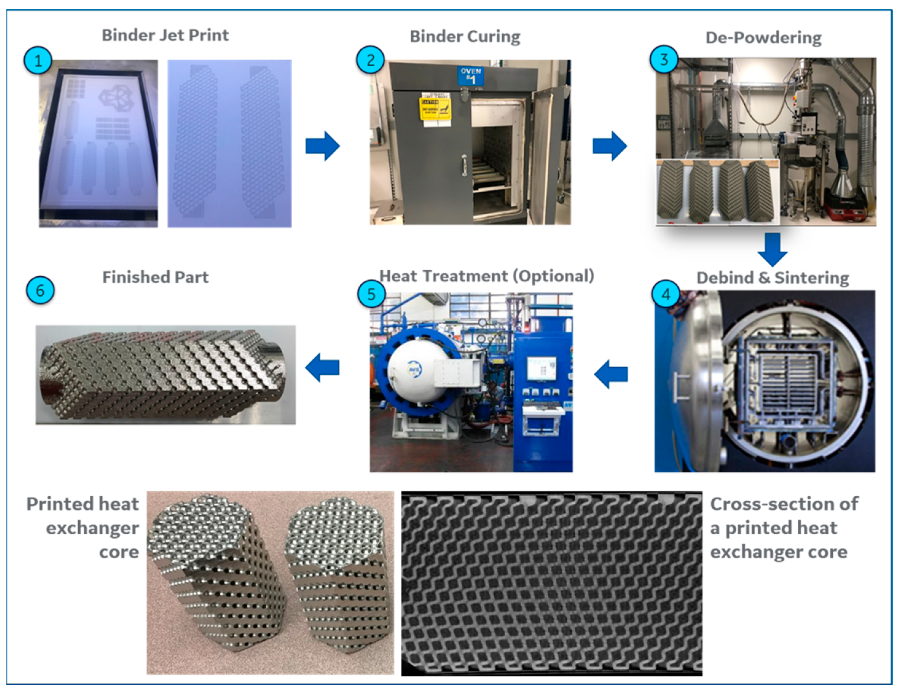
As shown in Figure 2, the BJ process begins with the printing step. This involves spreading a layer of powder on the print bed. Following this, a print head passes over the build platform and deposits a liquid binding agent to the powder. The deposited binder follows the 2D cross-section of the part to be printed. After a layer is printed, infrared heating is used to heat the print bed and cure the binder. The build platform is then lowered, and a new layer of powder is recoated. This process is repeated until the 3D part is completely printed.
The printed part is then cured. This step involves the evaporation of solvents to fully cure the binder. It is to be noted that binder curing is an optional step which depends on the characteristics of the powder and the printing machine, among others. Once the part is cured, it is taken to a separate station for powder removal. Based on the geometry of the part, powder removal can have various stages. For the heat exchanger core shown in Figure 2, de-powdering is carried out in two steps. The first step involves rough de-powdering, where a vacuum is used to evacuate loose powder from the exterior of the printed region. Once this is completed, fine de-powdering is performed, where powder is removed from the internal passages. This step may involve the use of mechanical vibrations in multiple orientations to remove the loose powder, aided by pressurized air flow to further accelerate powder removal. The de-powdering process is carried out until the printed part meets the specified target for powder removal. After completion of the curing and subsequent de-powdering process, the printed part is referred to as a ‘green part’. This part consists of powder particles held together by a cured or solidified binder. It is to be noted that the metal powder typically occupies 50–65% of the volume of the green part, while the rest is a binder and porosity. As such, the green part is expected to volumetrically shrink during densification.
The green part is then de-binded and sintered. De-binding refers to the process where the residual binder is removed from the part. Any residual binder could significantly impact the microstructure and properties of the sintered part. As such, the de-binding process is optimized based on the binder and the alloy being printed. Following the de-binding process, the parts are sintered at an elevated temperature, during which the metal powder particles coalesce, and the part densifies to a sintered state. The shrinkage that happens during sintering can be significant—parts in the printed state may have a porosity between 35–60% and, after printing, this porosity is reduced to <5%. In addition to shrinkage, during the sintering process, the parts may also be subjected to distortion or warpage induced by external forces, such as gravity.

2.2. Powder and Materials Characterization

The additive manufacturing process can be categorized into printing, de-powdering, and sintering processes. This work focuses on the characterization of the powder used for printing, and material properties after sintering.
The powder particle size distribution was characterized using a Microtrac S3500 analyzer (Microtrac MRB, Montgomeryville, PA, USA). The Microtrac uses a laser system to analyze the particle size. This is accomplished by using one or more laser sources projected onto a powder in suspension. The reflected laser light from the powder is then sensed by a detector. The detected signal is processed to parse out in the frequency and amplitude domain to correlate with known frequency responses of particle sizes. This process allows the evaluation of the entire particle size distribution. Subsequently, the powders were tested for flow using an ASTM standard Hall flowmeter (FBS-1002, Serial number: 201910091816, China).
For evaluation of the sintered materials properties, a temperature-dependent tensile test matrix was completed, followed by creep testing at elevated temperatures. The aim was to establish a baseline for tensile and creep properties of SS316L printed and sintered using BJAM. To understand the microstructure and chemical composition of the sintered material, backscatter electron microscopy and energy-dispersive X-ray spectroscopy (EDS) were performed. The backscattered electron images were taken on a Hitachi SU-70 FEG-SEM (Hitachi, USA) with an yttrium-aluminum garnet (YAG) scintillator detector and a Bruker XFlash 6 60-mm2 SDD EDS detector (Bruker, USA).

3. Results and Discussion

3.1. Powder Characterization

During the printing step, the flowability of the powder can affect the recoating process. Furthermore, the powder morphology, size distribution, and surface chemistry can affect the packing fraction of the green part. The packing fraction refers to the ratio of the density of the green part relative to the fully dense part of the same dimension. To understand and optimize the capability of the printing process, four lots of SS316L powder with different sized distributions were studied. They consist of one lot of fine (0–25 micron) gas atomized (GA) powder and three separate lots of medium-sized (20–50 micron) gas atomized powders. The powder lots are listed in Table 1.
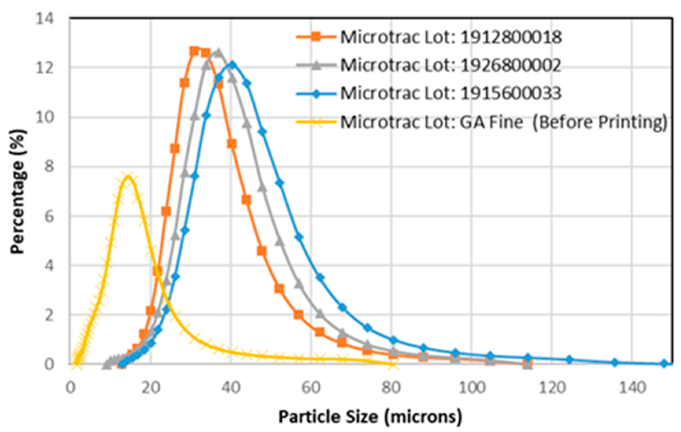
The four powder lots were characterized using a commercial Microtrac S3500 analyzer, as mentioned previously. The particle sizes for the GA fine lot have D10, D50, and D90 within twenty-two microns and are significantly smaller than the three GA medium lots.
Figure 3 shows the particle size distribution (PSD) curves of the four lots. In this study, the distribution functions of the lots are approximately similar, so it can be concluded that the GA medium lots get progressively coarse from GA medium lot 1 to 3. Finer powder distributions perform better during sintering. However, they may have other debits, such as poor flowability.
Powder flowability can affect multiple processes such as (a) the recoating process, where powder is deposited onto the powder bed and the surface of the bed is smoothened by using a roller, and (b) the de-powdering process, where the loose power is removed from the green part. To this end, the powders were tested for flow using an ASTM standard Hall flowmeter. The flow testing was conducted as per ASTM standard B212-17.
Table 2 shows the results of the Hall flow testing. The data is presented as time taken in seconds for a 50-g sample of powder to completely flow through the funnel. The fine powder has the lowest flow of all the lots tested and does not flow through the Hall flowmeter setup, resulting in a no-flow measurement. This can be attributed to the fact that finer particle size distributions have a lower flow rate than coarser particles under comparable conditions. The GA medium lots 1, 2, and 3 have flow times between 12.9 to 14.2 s. The fastest flowing lots are GA medium lots 2 and 3 at 12.7 and 12.9 s, respectively. The similarity in flow rates between lots 2 and 3 can also be attributed to the fact that the PSD curve (Figure 3) is similar between the two lots.
Another factor in powder selection is the green density after printing. Although not discussed in detail, all four powder lots resulted in comparable green densities. As a result, the GA medium 2 powder was selected, since it performed best for flowability.
After powder characterization, a limited print parameter optimization was performed using the GA medium 2 power lot, to ensure optimal green part characteristics. There are typically 70–100 individual print process parameters, such as the included layer thickness, recoat roller speed, revolutions per minute (RPM), infrared lamp intensity for bed temperature, powder feed per layer, etc. This process included printing cubes and rectangular bars, as shown in Figure 4. Since the scope of this effort was to evaluate the material’s capability for heat exchangers, the design of experiments was limited to optimizing the bed temperature, binder saturation, and binder curing time, while keeping the rest of the print parameters unchanged. The objective of the exercise was to obtain optimal surface resolution and green strength. Note that the green density was also measured for this exercise, but the parameters tuned in this optimization study did not typically affect the powder packing and the green density remained unaffected.

3.2. Materials Testing

The tensile strength and creep properties of the SS316L specimen produced using BJAM, measured and reported in this section, are only applicable to the combination of binder jet machine used, selected powder type and size distribution, binder jet printing profile, and sintering profiles used as part of this study. The properties may be further improved by optimizing one or more of the process parameters.

3.2.1. Tensile Strength

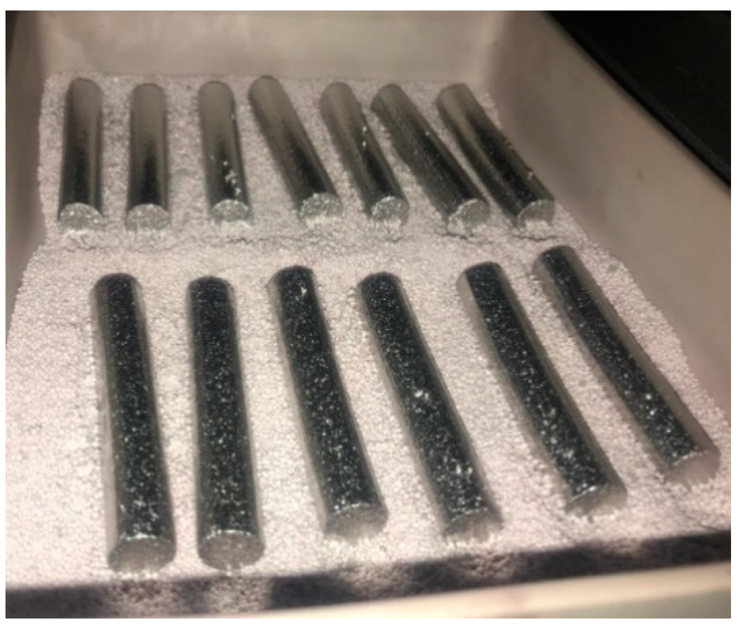
Binder Jet printed, and sintered coupons were tested for tensile materials properties at temperatures from 75 °F to 1076 °F (24 °C to 580 °C). At each temperature, five samples were tested to evaluate confidence intervals for the materials properties. Figure 5 shows the tensile coupons after they were printed and sintered. The coupons were printed as cylindrical blanks, which were subsequently machined to the test drawing specifications.
Figure 6a,b shows the measured 0.2% Yield Strength (YS) and Ultimate Tensile Strength (UTS) for the Binder Jet coupons. The measured properties are also compared with the cast properties for SS316L, available from the literature. Over the temperature range considered, the Binder Jet properties are in line with the reference data available from the literature. The properties are presented over a temperature range of 24–580 °C. The data for both YS and UTS obtained from testing the BJ printed and sintered samples are presented along with error bars for a ±95% confidence interval. Over the temperature range examined, the Binder Jet properties are in line with the reference data on cast SS316L available from the literature. A few observations regarding the Binder Jet process can provide some clarity for this observation. Firstly, this process does not affect the alloy chemistry. The only addition during the printing process is a binder, which is then removed during the de-binding process. As a result, the process of sintering involves grain growth and solid-state diffusion, resulting in a densification of the overall part, without altering the composition of the material itself. Secondly, the sintering process typically results in an equiaxed grain structure, in absence of any mechanism for preferential grain growth or elongation along a certain direction. These two factors enable the mechanical tensile properties of the BJAM SS316L to be like that of the cast material. Note that the grain sizes obtained during sintering are typically smaller than that of cast material, which could lead to differences in creep and fatigue properties. Some of this evaluation, especially relevant to creep, will be explored in a later section.
As part of the statistics related to tensile property evaluation, Table 3 lists the mean and 95% confidence intervals for the YS and UTS at the four test temperatures. The lower bound of the 95% confidence interval is at or higher than the 80% value of the base material obtained from literature.

3.2.2. Creep Testing

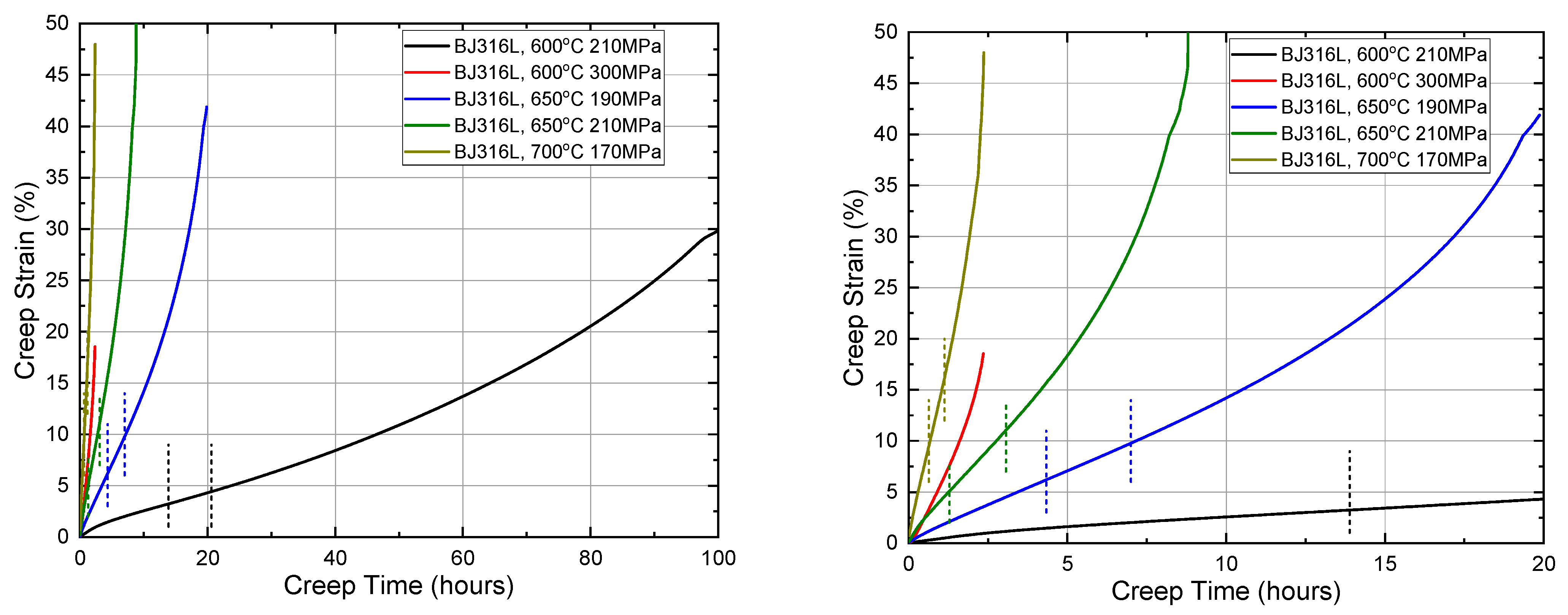
Preliminary finite element stress analysis on the heat exchanger suggests that the worst creep condition during operation is at or below ~588 °C, with a stress of 68 MPa (based on a pressure difference of 17 MPa across the wall). This creep condition is likely to take an extremely long creep time to achieve a reliable minimum creep rate or reach final creep rupture, based on the existing wrought and welded SS316L data. Therefore, five testing conditions with accelerated creep conditions at higher temperatures (600~700 °C) and stress levels (190~300 MPa) were designed to establish baseline creep properties of BJAM 316L (see Table 4).
Over-sized cylindrical pins were printed in Binder Jet and sintered using the baseline condition. A final density of 98% was achieved after sintering. The pins were then machined into screw-threaded dog-bone specimens with a 25.4 mm (1 inch) gage length, a 6.35 mm (0.25 inch) gage diameter, and an overall length of 76.2 mm (3 inch). Uniaxial tensile creep testing in air was conducted and tested until creep rupture at Joliet Metallurgical Laboratory. Creep curves are plotted in Figure 7. The five creep curves all show a brief period of primary and secondary creep with extended tertiary creep regime and high creep rupture ductility. The primary creep regime, where the creep rate decreases, is a relatively short period. The secondary creep or steady-state creep regime is indicative of a constant creep rate, as dislocation accumulation and annihilation achieve a balance. Extended tertiary creep (where the creep rate continuously increases) is observed for these samples, possibly due to the high creep stress applied for accelerated tests.
Larson Miller parameters are plotted in Figure 8, together with literature data of wrought, welded, and cast 316/316L. The conservative creep requirement of 20~40 years, assuming the worst condition of 588 °C and 68 MPa, is also displayed by a horizontal line. The left end of the horizontal line represents 20 years of life, and the right end represents 40 years of life, based on calculations of the Larson Miller Parameter at 588 °C and 68 MPa.
Weld metal or cross weld joints typically show a creep strength reduction compared to base metal. The amount of delta ferrite in the weld largely affects the weld strength reduction factor by phase transformation of delta ferrite into sigma phase that consequently lowers creep rupture ductility. E-beam and laser welding [17] are reported to generate no delta ferrite in the weld, and thus improve the weld creep strength reduction compared to conventional fusion welding. Higher nitrogen in SS 316L [18] is reported to be beneficial for creep resistance via solid solution strengthening and short-range ordering. However, the effect of nitrogen on creep life is not conclusive when comparing all the literature data with various nitrogen levels. Other microstructure influences (i.e., grain size, retained delta ferrite, specimen orientation relative to rolling direction) because of processing history cannot be ruled out, but such details are not fully provided in the cited papers. Rieth et al. [19] generated extremely valuable long-term creep data at 550 °C and 600 °C from multi-year testing. They reported creep mechanism shifts from power-law breakdown (dislocation glide) to power-law creep climb, when the creep stress is below ~200 MPa at 600 °C and below ~120 MPa at 550 °C. Furthermore, long-term microstructure instability caused by carbides, Laves, and Sigma phases is concluded not to be the reason for the power-law slope change in long-term creep data.
Compared to wrought and welded SS316L data, the creep properties of baseline Binder Jet SS316L is on the low end. The creep rupture time of the baseline testing is approximately one order of magnitude lower than the average creep rupture time of wrought/welded SS316L in the literature. A trendline (green dash lines) is drawn by extrapolating data to low stress region. This trendline might be subjective without creep test data below 170 MPa. However, it shows directionally that BJ SS316L has the potential to meet the operating conditions. The projected life at 588 °C and 68 MPa is approximately above 20 years, which is encouraging for this application. Further enhancement to creep properties is suggested based on a more detailed study of the microstructure.
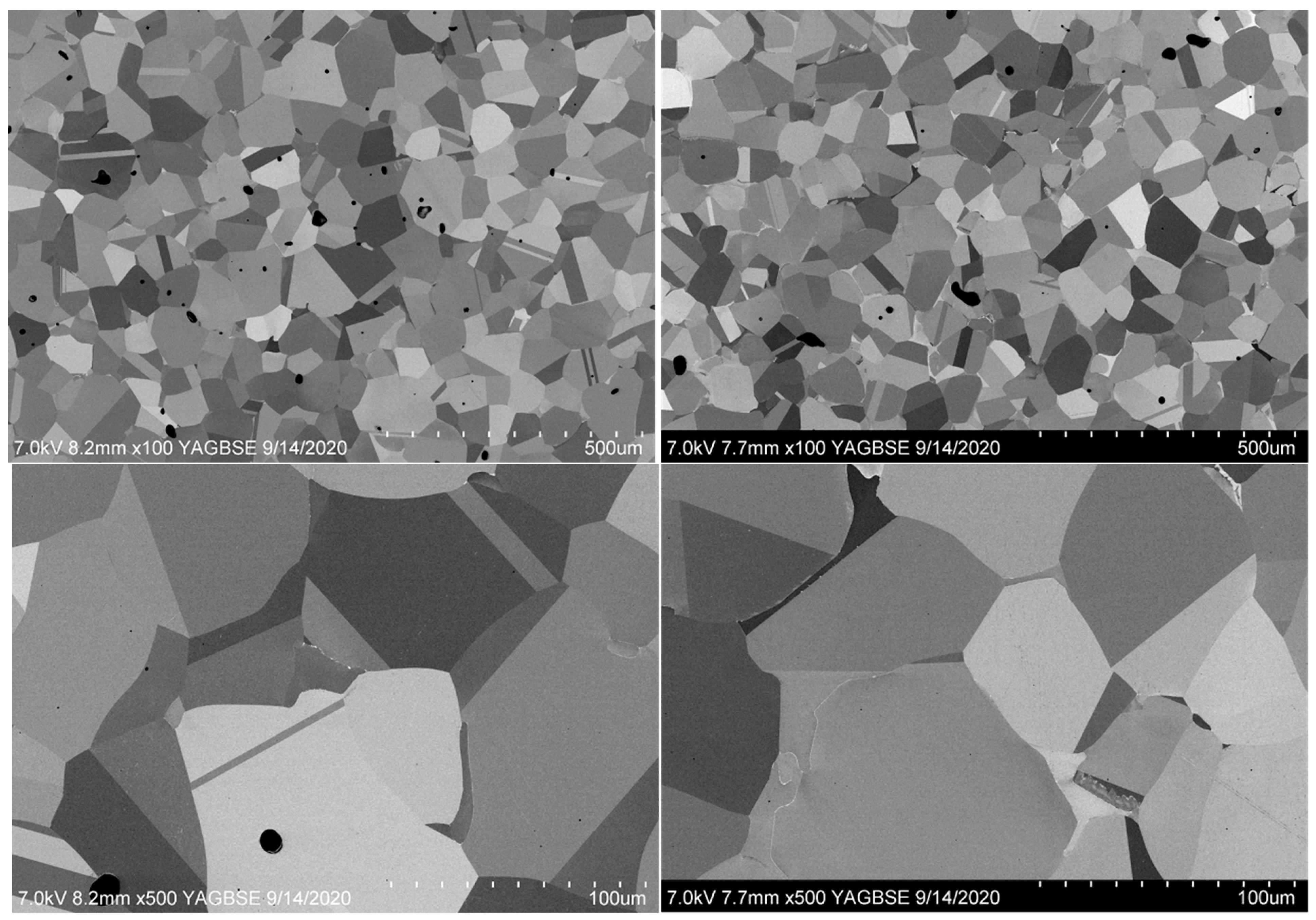
To understand the effect of the sintering cooling rate on the microstructure and creep properties, SEM characterization on the as-sintered coupons from the baseline additive process and a modified process with a faster cooling rate during sintering have been performed (see Figure 9). For simplicity, the baseline process will be referred to as Build 1, and the modified process will be referred to as Build 2. The line intercept method was applied to multiple images taken at random locations to estimate the average grain size. Build 1 shows an average grain size of 84 µm and Build 2 shows a similar grain size of 78 µm. The porosity of sintered samples listed here were quantified using the Archimedes density principle, which involves calculating the density based on measurements of the weight of the samples relative to the volume of liquid displaced by the specimen. Bulk density of sintered Build 1 and 2 coupons using the Archimedes density method are 98.7% and 97%, respectively. Interestingly, a qualitative inspection of the SEM images reveals slightly higher porosity in Build 1 than in Build 2. This could be due to a non-uniform porosity distribution in the specimen. On another note, both samples have an equiaxial grain shape. There are bright-contrast layers and grains of a different phases at grain boundaries.
Energy-dispersive X-ray spectroscopy (EDS) was utilized to indicate the chemical composition of this new phase, as shown in Figure 10 and Figure 11. EDS maps suggest this new phase is delta ferrite rich in Mo, Cr, and lean in Ni compared to austenite grains. The bright contrast layer is rich in Mo. Thermodynamic equilibrium phase predictions were performed using ThermoCalc software and the TCFe9 database (Figure 12). The other minor phases are predicted in low quantities, including MnS sulfide, HCP_A3#2 chromium nitride, M23C6 Cr, Mo rich carbide, Chi phase rich in Fe, Mo, Cr rich, Laves phase rich in Fe and MO, Sigma phase rich in Fe and Cr. Some of these phases, such as Chi, Laves, and Sigma phases only form during long-term exposure at high temperatures. Phase transformation from metastable delta ferrite formed in welds to stable sigma phase during long-term creep tests has been reported to degrade creep ductility and embrittle material, resulting in reduced creep resistance [25,26]. The predicted delta ferrite phase composition is rich in Mo, Cr, and lean in Ni compared to the austenite phase, which further confirms that the grain boundary phase is delta ferrite. The sintering temperature 1330–1400 °C is at the austenite/delta ferrite phase region. Upon fast cooling, the material could have retained delta ferrite that does not fully transform back to austenite. A faster cooling rate from sintering cycle was observed to degrade creep properties and result in shorter creep rupture time. The faster cooling rate in the Build 2 sintering process may lead to a higher fraction of delta-ferrite, which is believed to be the reason for the creep discrepancy between Build 1 and 2. It is known in the literature that delta-ferrite is detrimental to creep resistance. The lesson learned from this study is that the sintering temperature and the cooling rate of the sintering process are crucial to the amount of retained delta ferrite and creep properties. Sintering profile parameters should be well defined and monitored for process variability in Binder Jet mass production.
A clear technical path to improve creep resistance includes powder and process optimization studies towards achieving an optimal microstructure:
  • powder size distribution
  • powder composition
  • build parameters
  • binder material
  • sintering profile
The powder and process optimization studies are outside the scope of this paper.

4. Conclusions

A Binder Jet Additive Manufacturing process was developed and applied to print heat exchanger cores for a supercritical CO2 power cycle. The study showed that gas atomized SS316L powder could be used to print cores for the heat exchanger using the process. Baseline materials property testing showed that the tensile properties of 3D printed SS316L were comparable to that of casting over a temperature range of 24 °C to 580 °C.
Baseline creep properties were established for BJAM SS316L for the first time. A literature survey of creep properties showed that a wide range of Larson Miller parameters could be obtained with varying manufacturing processes and variations in elemental composition of the alloy. The baseline Binder Jet creep properties of SS316L currently fall at the lower end of cast/wrought/welded SS316L data from the literature.

Author Contributions

Conceptualization, W.D.G.; methodology, W.D.G.; D.J.E., Y.W., S.J., A.B., S.H., and N.T.; validation, A.B., N.T.; formal analysis, D.J.E., Y.W., S.J.; investigation, S.J., A.B., S.H., and N.T.; data curation, N.T., S.H., A.B.; writing—S.J., N.T., S.H., A.B.; writing—review and editing, N.T., S.H., A.B.; visualization, N.T., S.H., A.B.; project administration, W.D.G., and N.T.; funding acquisition, W.D.G. All authors have read and agreed to the published version of the manuscript.

Funding

This research was funded by the U.S. Department of Energy’s Office of Energy Efficiency and Renewable Energy (EERE) under the Solar Energy Technology Office (SETO) Award Number DE-EE0008737. This report was prepared as an account of work sponsored by an agency of the United States Government. Neither the United States Government nor any agency thereof, nor any of their employees, makes any warranty, express or implied, or assumes any legal liability or responsibility for the accuracy, completeness, or usefulness of any information, apparatus, product, or process disclosed, or represents that its use would not infringe privately owned rights. Reference herein to any specific commercial product, process, or service by trade name, trademark, manufacturer, or otherwise does not necessarily constitute or imply its endorsement, recommendation, or favoring by the United States Government or any agency thereof. The views and opinions of authors expressed herein do not necessarily state or reflect those of the United States Government or any agency thereof.

Institutional Review Board Statement

Not applicable.

Informed Consent Statement

Not applicable.

Data Availability Statement

All data generated pertaining to this document is presented in this article as Figures or Tables.

Acknowledgments

In addition to the authors listed above, other GE Research team members who contributed to the BJAM process and to the materials characterization efforts are listed as follows—William Alberts and John Morrison for Binder Jet Manufacturing; Rebecca Casey, and Mike Knussman for metallography and characterization support.

Conflicts of Interest

The authors declare no conflict of interest.

References

  1. Barua, A.; Gerstler, W.D.; Erno, D.J.; Wang, Y. Binderjet Additive Manufacturing for Complex Heat Exchanger Geometries. In Proceedings of the SolarPACES 2020, Online, 28 September 2020. [Google Scholar]
  2. Kwon, J.S.; Son, S.; Heo, J.Y.; Lee, J.I. Compact heat exchangers for supercritical CO2 power cycle application. Energy Convers. Manag. 2020, 209, 112666. [Google Scholar] [CrossRef]
  3. Li, W.; Yu, Z. Heat exchangers for cooling supercritical carbon dioxide and heat transfer enhancement: A review and assessment. Energy Rep. 2021, 7, 4085–4105. [Google Scholar] [CrossRef]
  4. Naveenan Thiagarajan, W.D. Novel Binderjet Additive HXs—A Pathway to 5¢/kWh CSP. In Proceedings of the Gen3 CSP Summit 2021, Virtual Event, 25–26 August 2021. [Google Scholar]
  5. Frazier, W.E. Metal additive manufacturing: A review. J. Mater. Eng. Perform. 2014, 23, 1917–1928. [Google Scholar] [CrossRef]
  6. Stornelli, G.; Faba, A.; Di Schino, A.; Folgarait, P.; Ridolfi, M.R.; Cardelli, E.; Montanari, R. Properties of Additively Manufactured Electric Steel Powder Cores with Increased Si Content. Materials 2021, 14, 1489. [Google Scholar] [CrossRef] [PubMed]
  7. Ziaee, M.; Crane, N.B. Binder Jetting: A Review of Process, Materials, and Methods. Addit. Manuf. 2019, 28, 781–801. [Google Scholar] [CrossRef]
  8. Patternmaker Sees Future in 3D. Mod. Cast. 2013, 103, 24–25.
  9. Almaghariz, E.S. Quantifying the role of part design complexity in using 3D sand printing for molds and cores. Int. J. Met. 2016, 10, 240–252. [Google Scholar] [CrossRef] [Green Version]
  10. Franchetti, M.A.; Kress, C. An economic analysis comparing the cost feasibility of replacing injection molding processes with emerging additive manufacturing techniques. Int. J. Adv. Manuf. Technol. 2017, 88, 2573–2579. [Google Scholar] [CrossRef]
  11. Kress, C. An Experimental and Theoretical Analysis of Additive Manufacturing and Injection Molding. Ph.D. Thesis, The University of Toledo, Toledo, OH, USA, 2015. [Google Scholar]
  12. Günther, D.A. Additive manufacturing of casting tools using powder-binder-jetting technology. In New Trends in 3D Printing; Intech: London, UK, 2016; pp. 53–85. [Google Scholar]
  13. Bai, Y.; Williams, C. An exploration of binder jetting of copper. Rapid Prototyp. J. 2015, 21, 177–185. [Google Scholar] [CrossRef] [Green Version]
  14. Lores, A.; Azurmendi, N.; Agote, I.; Zuza, E. A review on recent developments in binder jetting metal additive manufacturing: Materials and process characteristics. Powder Metall. 2019, 62, 267–296. [Google Scholar] [CrossRef]
  15. Byun, T.S.; Lach, T.G. Mechanical Properties of 304L and 316L Austenitic Stainless Steels after Thermal Aging for 1500 Hours; PNNL-25854; US Department of Energy/Office of Nuclear Energy: Richland, WA, USA, 2016. [Google Scholar]
  16. Sandvik. Material Datasheet. Sanmac 316/316L Bar. 2014. Available online: https://www.materials.sandvik/se/materialcenter/materialdatablad/bar-and-hollow-bar/bar/sanmac-316316l/?show=email-pdf (accessed on 17 July 2020).
  17. Tjong, S.C.; Zhu, S.M.; Ho, N.J.; Ku, J.S. Microstructural characteristics and creep rupture behavior of electron beam and laser welded AISI 316L stainless steel. J. Nucl. Mater. 1995, 227, 24–31. [Google Scholar] [CrossRef]
  18. Ryu, W.S.; Kim, D.W.; Kim, W.G.; Kuk, I.H. High temperature behaviors of type 316L (N) stainless steel. In Proceedings of the Transaction of the 15th International Conference on Structural Mechanics in Reactor Technology, Seoul, Korea, 15–20 August 1999. [Google Scholar]
  19. Rieth, M.; Falkenstein, A.; Graf, P.; Heger, S.; Jäntsch, U.; Klimiankou, M.; Materna-Morris, E.; Zimmermann, H. Creep of the Austenitic Steel AISI 316 L (N). Experiments and Models. (No. FZKA--7065); Forschungszentrum Karlsruhe GmbH Technik und Umwelt (Germany), Inst. fuer Materialforschung-Programm Kernfusion: Karlsruhe, Germany, 2004. [Google Scholar]
  20. Brinkman, C.R. Long-Term Creep and Creep-Rupture Behavior of Types 304 and 316 Stainless Steel, Type 316 Casting Material (CF8M), and 2 1/4 Cr-1 Mo Steel. Final Report (No. ORNL/TM-9896); Oak Ridge National Lab: Oak Ridge, TN, USA, 1986. [Google Scholar]
  21. Ravi, S.L.; Laha, K.; Mathew, M.D.; Vijayaraghavan, S.; Shanmugavel, M.; Rajan, K.K.; Jayakumar, T. A comparison of creep deformation and rupture behaviour of 316L (N) austenitic stainless steel in flowing sodium and in air. Procedia Eng. 2013, 55, 823–829. [Google Scholar] [CrossRef] [Green Version]
  22. Sasikala, G.; Mathew, M.; Bhanu, S.; Mannan, S. Assessment of Creep Behaviour of Austenitic Stainless Steel Welds; No. IAEA-TECDOC—933; International Atomic Energy Agency: Vienna, Austria, 1997. [Google Scholar]
  23. Sakthivel, T.; Vasudevan, M.; Laha, K.; Parameswaran, P.; Chandravathi, K.S.; Mathew, M.D.; Bhaduri, A.K. Comparison of creep rupture behaviour of type 316L (N) austenitic stainless steel joints welded by TIG and activated TIG welding processes. Mater. Sci. Eng. A 2011, 528, 6971–6980. [Google Scholar] [CrossRef]
  24. Sasikala, G.; Matthew, M.; Rao, B.S.; Mannan, S. Creep Deformation and Fracture Behavior of Types 316 and 316L(N) Stainless Steels and Their Weld Metals. Metall. Mater. Trans. A 2012, 31, 1175–1185. [Google Scholar] [CrossRef]
  25. Nassour, A.; Bose, W.W.; Spinelli, D. Creep properties of austenitic stainless-steel weld metals. J. Mater. Eng. Perform. 2001, 10, 693–698. [Google Scholar] [CrossRef]
  26. Mathew, M.; Latha, S.; Bhanu, S. An assessment of creep strength reduction factors for 316L(N) SS welds. Mater. Sci. Eng. A 2007, 456, 28–34. [Google Scholar] [CrossRef]
  27. Sakthivel, T.; Vasudevan, M.; Laha, K.; Parameswaran, P.; Chandravathi, K.S.; Mathew, M.D.; Bhaduri, A.K. Creep rupture strength of activated-TIG welded 316L (N) stainless steel. J. Nucl. Mater. 2011, 413, 36–40. [Google Scholar] [CrossRef]
Figure 1. High temperature binder jet HXs—(a) Trifurcating flow path (b) fabricated SS316L HX core and modular assembly options.
Metals 13 00617 g001
Figure 2. Overall BJAM process—printing, curing, de-powdering, and sintering steps. The two images at the bottom of the figure show the printed and sintered core, and a cross-section of the heat exchanger’s internal flow passages. Reprinted/adapted with permission from [4]. Copyright—2020, General Electric.
Metals 13 00617 g002
Figure 3. D10, D50, and D90 size characterization of the four powder lots selected in the study.
Metals 13 00617 g003
Figure 4. Results from print parameter optimization showing green parts with (a) build quality from initial parameter set, and (b) build quality from optimized parameter set.
Metals 13 00617 g004
Figure 5. Sintered tensile test blanks.
Metals 13 00617 g005
Figure 6. (a) Summary of Yield Strength of the Binder Jet coupons over a temperature range of 24–580 °C (75–1076 °F), compared to cast properties of SS316L material available from the literature [15,16] and (b) summary of ultimate tensile strength of Binder Jet coupons.
Metals 13 00617 g006
Figure 7. Creep curves for baseline Binder Jet 316L. Left: full creep curves. Right: enlarged view for the shorter tests. Two vertical dash lines on each curve (except 600 °C 300 MPa curve) indicate the transition from primary creep to secondary creep and the transition from secondary creep to tertiary creep.
Metals 13 00617 g007
Figure 8. Larson Miller plot showing the compiled cast, wrought and welded 316L creep data in the literature [17,18,19,20,21,22,23,24,25,26,27], together with Binder Jet 316L baseline data in the present work.
Metals 13 00617 g008
Figure 9. Backscattered electron images of as-sintered coupons from Build 1 (baseline-left top and bottom) and Build 2 with a faster cooling rate (right-top and bottom).
Metals 13 00617 g009
Figure 10. EDS mapping of Build 1 showing the Mo, Cr rich grain, and Mo rich layer.
Metals 13 00617 g010
Figure 11. EDS mapping of Build 2 showing the Mo, Cr rich grain, and Mo rich layer.
Metals 13 00617 g011
Figure 12. ThermoCalc prediction of equilibrium phases in SS316L as a function of temperature. BCC_A2 is the delta-ferrite phase. FCC_A1 is the austenite phase.
Metals 13 00617 g012
Table 1. Powder lots selected for characterization study.
Lot NameD10 (Microns)D50 (Microns)D90 (Microns)
GA Fine (Before Printing)5.212.622.6
GA medium 122.631.746.7
GA medium 224.135.151.1
GA medium 326.438.657.5
Table 2. Hall flow testing for four powder lots, averaged over three tests for each powder lot.
Lot NameTime (s)
GA Fine (Before Printing) no flow
GA medium 114.2
GA medium 212.7
GA medium 312.9
Table 3. Summary of the Yield Strength and Ultimate Tensile Strength values of the Binder Jet SS316L material, compared with the relevant properties of the cast material from the literature. Note that the lower 95% confidence interval of the BJ data meets or exceeds.
BJAM-0.2% Yield (ksi)80% Yield Strength Target (of Cast Material)
Temperature (°F)Temperature (°C)Average95% CI Upper Bound95% CI Lower Bound
7523.931.033.728.427
400204.423.924.723.219
800426.719.626.113.013
107658018.319.716.910
BJAM-UTS (ksi)80% UTS Target (of Cast Material)
Temperature (°F)Temperature (°C)Average95% CI Upper Bound95% CI Lower Bound
7523.980.586.774.361
400204.460.665.755.546
800426.757.760.455.142
107658050.354.046.640
Table 4. Creep test conditions under constant temperature and stress, and the resulting creep rupture time for each test specimen.
Temperature (°C)Stress (MPa)Rupture Time (Hours)
7001702.4
6502108.8
65019019.9
6003002.4
600210106.2
Disclaimer/Publisher’s Note: The statements, opinions and data contained in all publications are solely those of the individual author(s) and contributor(s) and not of MDPI and/or the editor(s). MDPI and/or the editor(s) disclaim responsibility for any injury to people or property resulting from any ideas, methods, instructions or products referred to in the content.