Review

Green Approach for Electropolishing Surface Treatments of Additive Manufactured Parts: A Comprehensive Review

Department of Chemical Engineering, Materials and Industrial Production, Piazzale Tecchio 80, 80125 Napoli, Italy
*
Author to whom correspondence should be addressed.
Metals 2023, 13(5), 874; https://doi.org/10.3390/met13050874
Submission received: 27 February 2023 / Revised: 21 April 2023 / Accepted: 26 April 2023 / Published: 30 April 2023

Abstract

:
Over the years, the widespread diffusion of additive manufacturing, especially to produce metal objects, and the awareness of their poor surface quality due to the presence of a significant roughness, have highlighted the need to develop suitable post-processing surface treatments. In this regard, electropolishing techniques are ideal due to their high versatility, even on geometrically complex or small-sized objects, which are difficult to treat with techniques that require physical contact with a tool. On the other hand, the common use of strong and dangerous acid baths does not allow compliance with increasingly stringent sustainability criteria. For this reason, special attention is increasingly directed toward the identification of green electrolytes, based on deep eutectic or acid-free solvents, potentially capable of replacing conventional acid solutions. The choice of new environmentally sustainable and specifically appropriate solvents according to the metal alloys treated could allow a further expansion of the additive processing technologies, and therefore preserve their advantage, extending, among other things, the demand for the related finished products thanks to their superior aesthetic and functional quality.

1. Introduction

Three-dimensional additive manufacturing (AM) technologies, born as a tool for the rapid prototyping of industrial components, have acquired significant attraction in recent years from manufacturing industries and research universities [1]. They allow the production of near net-shaped objects with complex and sophisticated geometries, even with internal channels and thin-walled structures, by reducing production time and cost, with respect to conventional technologies. Just think to the stents with their filigree shape, which requires high precision [2]. The world market for AM objects is estimated to reach USD 76.16 billion, with a compound annual growth rate (CAGR) of 20.8% in 2030, according to a new report by Grand View Research, Inc. The AM processes used to produce metal objects are several, namely powder bed fusion (PBF), directed energy deposition (DED), and binder jetting (BJ) [3]. The most used technologies based on the use of powder bed fusion (PBF) are selective laser melting (SLM) and electron beam melting (EBM) [4]. The additively built-up pieces, very often, present superior mechanical and electrochemical properties compared to the casting counterparts [5], but one of their drawbacks is represented by their poor surface finish, affected by high roughness (in some cases around 50 µm [6]), together with edges, corners, and discolouration [7]. The roughness defects arise from balling and rippling effects, the presence of stocked un-melted or partially melted particles (see Figure 1), the stair-step effect, when angled or curved parts are built, the presence of oxide particles [8], micro-crack, microporosity [9], and droplet columns [10].
The surface quality of the AM parts is strongly influenced by both the powders or wire feedstock characteristics and the process parameters [11]. It is worth remembering the additional advantage of re-using powders for the PBF technologies, which, however, could generate final products with different characteristics from those obtained from virgin powders. The optimisation of the AM processing parameters could partially reduce the above-mentioned issues; however, the resultant improvement is limited due to the intrinsic randomness of the powder feedstock properties. The poor quality of the surface of the components produced by AM constitutes a significant drawback in extending this technique to real industrial production, since a rough surface easily triggers fatigue and corrosion problems, limiting their durability. The reduction of surface roughness through post-processing treatments becomes a necessary condition to enhance their performance and to extend their application in various industrial fields. The traditional surface post-processing such as sandblasting [12,13] and shot peening [14,15], responsible for residual stresses and deformations already for products of simple geometry [16], are certainly difficult to apply to parts of more complex geometry, perhaps including channel internals, such as those obtainable through AM. An alternative technique could be laser polishing, which consists in remelting the object to smooth the surface [17], but this treatment, although effective on the upper surface of the parts, is difficult to apply to the internal ones. Another technique examined for the surface post-treatment of simple and complex AM parts is chemical polishing [18], but the results obtained do not seem satisfactory due to the permanence of a residual roughness due to a uniform, not selective, attack or pitting phenomena. Furthermore, this technique is disadvantaged by using toxic and dangerous reagents and, therefore, has a negative impact from the environmental point of view [19]. Electrical discharge machining is another technique proposed to improve the surface quality of the AM parts [20], but this technique based on the removal of asperity via heat from rapid electrical discharge requires high potential values, and involves continuous tool wear and thermal-related stress on samples. In the literature, some review papers presented the electropolishing treatment as a post-processing treatment using DESs on conventionally produced components, as Smith [21]. Chaghazardi, and R. Wüthrich deal with the EP treatment on additive-manufactured parts performed on acid solutions [22]. Basha et al. [23] briefly collected all papers dealing with the chemical and conventional or not conventional electrochemical polishing treatments, carried out in acid and acid-free solutions. This review aims to focus the attention only on papers that investigated the efficiency of the conventional electropolishing treatment applied on additive manufactured parts to highlight its potential for use under suitable green conditions and to support a future sustainable industry.

2. Electropolishing Treatment

The electropolishing treatment (EP) has gained considerable industrial interest thanks to its high efficiency and the possibility of being able to treat parts even with complex geometries, providing surface finishes with the desired level of roughness up to mirror polishing but avoiding the generation of residual stresses. It is well known, in general, that two surface qualities may be reached, namely anodic levelling and anodic brightening [24]. The former results from the different dissolution rates of the peaks and valleys of the substrate due to the primary current distribution, which leads to a reduction in the roughness of several microns. The latter improves the surface roughness due to control of the dissolution rate of the metal microstructure. In this frame, EP treatment is a material removal technique performed with simple equipment (see Figure 2) that essentially comprises a cell, a chiller to control the temperature, an agitation system, and a power supply connected by the positive terminal to the anode and the negative terminal to the cathode.
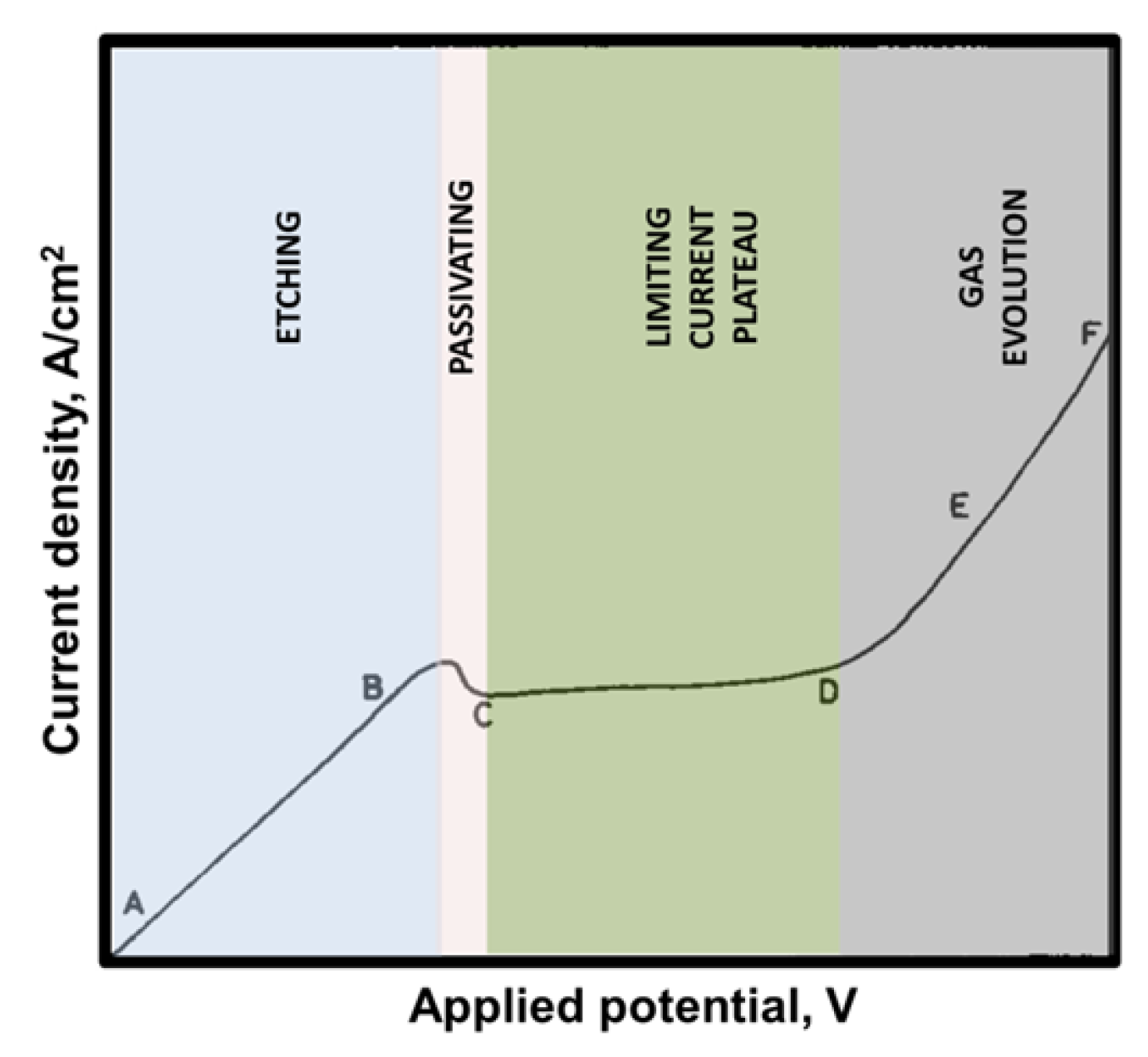
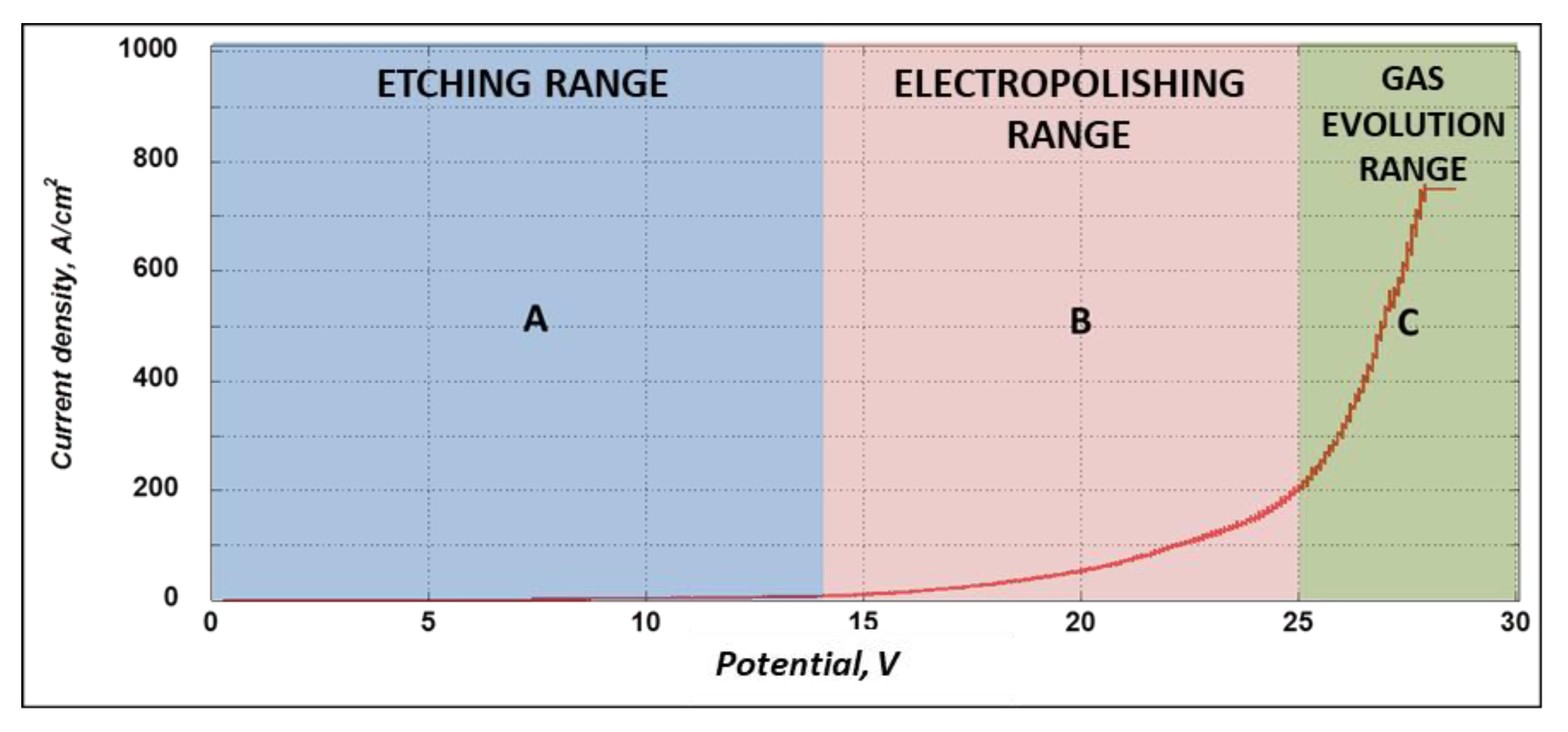
As for all electrochemical treatments, many parameters could affect the quality of the surface finish achieved by EP, such as the potential or current density applied, the temperature, the stirring rate, the anode–cathode distance, the chemical composition of the anode, and so on. By now, it is well known that the potential values for an efficient EP treatment must be identified by the potential–current density curve [25], as depicted in Figure 3, in which four zones have been detected: (1) etching (AB); (2) passivating(B–C); (3) limiting current plateau, known as the electropolishing range (C–D); and (4) gas evolution (D–F). The constant value of the current density with increasing applied potential recorded in the electropolishing range was the starting point to explain the possible finishing mechanism involved.
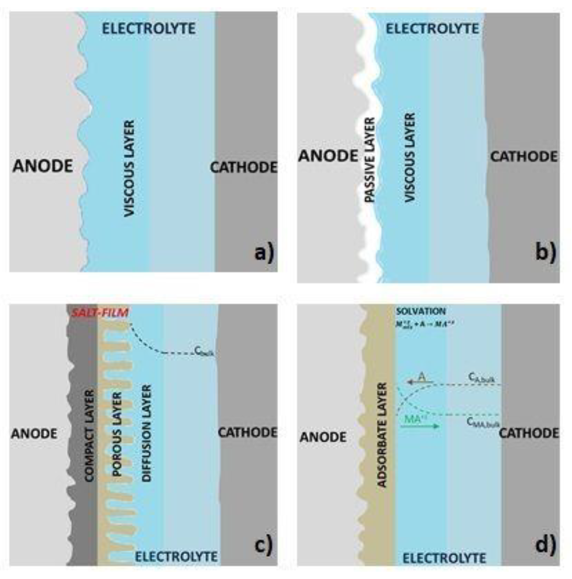
Jacquet [26], the first researcher to study the polishing mechanism of EP, asserted the probable formation of a viscous and dense layer on the anodic surface, composed of dissolved products stuck to it, and characterised by a flat surface on the side facing the electrolyte (i.e., independent of the anode roughness), as displayed in Figure 4a. Being thinner on the asperities and thick on the valleys, the electrical resistance between the cathode and the anode is different. Therefore, the peaks are dissolved faster than the hollows, causing a selective polishing effect on the piece’s surface. In other words, the mechanism proposed by Jacquet is based on the different ohmic resistance values between the cathode to the anode and the migration of the dissolved ions from the anode versus the bulk solution for the effect of the electrical field. Hoar and Mowat [27] assumed that the polishing action started from the formation of a thin passive film, a few cell units thick, immediately followed by its dissolution. In this case, the viscous layer is formed between the oxide passive film and the bulk of the electrolyte (Figure 4b), and it is thinner over peaks and thicker over the hollows. As a result, local current densities over the peaks are higher, leading to their faster dissolution.
Elmore [28] proposed the importance of diffusional phenomena to explain the smoothness of the surface during the EP treatment and from this assumption two other different mass transport mechanisms were derived: the salt film, according to which the dissolution product limited the transport mass, and the adsorbate-acceptor, predicting that the acceptor is limited to mass transport. The first kind of mechanism was found for the EP treatment of iron in phosphoric acid [29] or nickel in sulphuric acid [30]. In particular, Grimm and Landolt [31] proposed that the highly resistive behaviour was due to the formation of a salt film, as a result of metal cations kept on the electrode, beyond the limits of solubility. The salt film presents a duplex structure (Figure 4c), consisting of an internal compact layer characterised by high-field solid state conduction and a porous external one, in which a migration conduction through pores occurs under the electrical field effect. When the limiting-current plateau is reached, the steeper concentration gradient of cations on the peaks involves a greater diffusion of them, and so a smoothing of the surface. Matlosz [32] examined the role of adsorbed intermediates and acceptor-species transport during the EP. The author proposed the acceptor mechanism (Figure 4d), in which the transport rate towards the anode of acceptor species such as complexing ions or water is rate-limiting. These species, by reacting with the dissolving metal ions to form complexed or hydrated species, give rise to an insoluble salt film.
Currently, the effectiveness of an EP treatment, widely investigated by roughness measurements, is often performed through improper instruments, which have resolutions that could be higher or lower than the real roughness of components. The most used in the literature, but especially in the industrial field, is the contact stylus profilometer, which is low cost and user-friendly, employed for certifying component surfaces, according to the well-established ISO4287 standard. The technique is based on the scanning and characterisation of individual profiles traced on the surface, evaluating the roughness by means of the profile texture parameter Ra, the arithmetic average value of roughness, which is the most used roughness parameter. However, it gives limited and misleading information about the topography of a surface as reported by [33,34]. Although other parameters are evaluated, such as the root mean square deviation, Rq, the maximum height of the profile, Rz, and the total height of the profile, Rt, several profiles have to be captured to obtain indicative information, not a real description, of the surface. In addition, it is known that the topography of as-built additive manufacturing parts can be very rough, with a significantly contorted profile, characterised by pronounced re-entrant features [6], as shown in Figure 5, which could be inaccessible to a stylus. Thus, the profile base measurement could underestimate the result and give limited information about the topography.
As an alternative, areal roughness measurements could be performed to describe the texture in a three-dimensional Cartesian space using the areal roughness parameters [34], following the ISO25178 standard. For these analyses, a contactless instrument, such as a scanning confocal microscope, an opto-digital microscope [35], or X-ray computed tomography, may be more suitable [36,37]. A combination of the profile and areal roughness parameters is suggested by Moylan [38] for the characterisation of AM surfaces, also considering the kurtosis (Rku or Sku) and skewness (Rsk or Ssk) parameters. The former gives information relative to the relationship between the height distribution and a Gaussian distribution, whereas the latter provides an indication of relative predominance of peaks or valleys. A more sensitive and significant areal roughness parameter for the characterisation of the AM parts is the developed interfacial area ratio, Sdr, which estimates the extension of the “real” surface area contributed by the texture [6]. An additional parameter useful for characterising the efficiency of a post-processing treatment, such as the EP one, is the R∆q or its areal counterpart, S∆q [39], which is the root mean square value of ordinate slope dZ/dx, according to the ISO4287 standard. The more effective the treatment, the lower its value, suggesting that the reduction of the peaks contributes to the initial high roughness, and thus the smoothing of the surface. Further parameters evaluated for the same purpose are mass loss and penetration depth. However, in general, to avoid diminishing the benefits of additive manufacturing technology, all measurements cannot ignore any reductions in surface roughness already determined by additional treatments, usually preceding the EP finishing process.

3. Conventional Electropolishing as Post-Processing Treatment

In this section, the experimental evidence available in literature so far regarding the efficacy of EP as a post-processing surface treatment of additively manufactured objects is summarised.

3.1. Titanium-Based Additive Manufacturing Parts

Urlea and Brailovski [40] focused their attention on the influence of the initial roughness Ra, ranging from 4 µm (0°) to 23 µm (135°), of SLM Ti6Al4V components containing differently oriented surfaces on the EP effectiveness. The research showed a uniform roughness of 1–3 µm on all the variably-oriented surfaces. The authors also highlighted the importance of considering the design requirements, which comprise the nominal dimensions of the parts, i.e., the processing tolerances. Zhang et al. [41] studied the effect of EP duration time on the surface composition of SLM-produced Ti6Al4V ELI parts, with an initial Ra of about 6.3 µm and intended for biomedical applications. The results indicated that an electropolishing time of 15 minutes generates the lowest roughness, i.e., 1.1 µm. Furthermore, taking into account that the composition of the treated metal alloy is also important in this sector, the authors demonstrated that a surface composition of anatase and rutile TiO2, stable and with protective properties, also provides the best corrosion resistance in Ringer’s solution. Wu et al. [42] examined the influence of the EP on biocorrosion and mechanical properties of Ti6Al4V tensile test specimens produced by EBM technology, which conferred an initial roughness of 24 µm. The reduction of the surface roughness at about 4 µm after the EP treatment resulted in an improvement of the tensile strain from 7.6% to 11.6%, without any loss of both elastic modulus and strength, as well as in a better corrosion property. Pyka et al. [43] modified the surface cylindrical porous structure of SLM-fabricated Ti6Al4V parts characterised by an initial Ra of about 10 µm using chemical etching and electrochemical polishing treatments. Although the combined treatments allowed a reduction of the roughness, the authors noted a decrease of the mechanical properties.

3.2. Steel-Based Additive Manufacturing Parts

AISI 316L stainless-steel is widely used in industrial applications, such as material devices, the food industry, and even for watch and jewel components, mainly due to its high corrosion resistance in numerous environments and media and to the possibility of getting an excellent surface finish.
Kim and Park [7] performed the EP treatment on cylindrical shapes of 316 L stainless-steel fabricated by selective laser sintering, SLS, and a square-shaped wall having four inside corners using laser metal deposition, LMD. The authors demonstrated an improvement in the roughness and corrosion properties using an EP finishing treatment with high current densities, from 3.2 to 8.6 A/cm2 for 5 min. Langi et al. [44] reduced the roughness of SLM-manufactured 316 L stents of about 30%, performing a kind of “intermittent” EP treatment, with a total immersion time in the bath of 1.5 min divided into three steps of 30 s. The mechanical properties of the new products were comparable to those of commercial stents. Rotty et al. [45] studied the influence of the electrolyte temperature on EP treatment efficiency of laser additively manufactured 316 L parts, demonstrating that better results are obtained when applying the high values of temperature, together with the high potential indicated in the electropolishing range by the related potential–current curve, as will be mentioned in Section 2.

3.3. Nickel-Based Additive Manufacturing Parts

Inconel 718 and 625 are Ni-based alloys, widely used in the aerospace field for parts subjected to high temperature conditions, such as the gas turbine disks or heat exchangers, due to their good high-temperature strength, high toughness and corrosion resistance, excellent creep resistance, and good weldability. In contrast, they have a low machinability due to the high strength and self-hardening ability, leading to many difficulties in machining and post-processing treatment. Jain et al. [46] investigated the pulsed EP on SLM-fabricated Inconel 718, adopting a 3 × 3 full factorial experiment and changing three parameters, namely current density, polishing time, and duty cycle, at three different levels. The optimal surface finish resulted in 0.25 μm Ra applying a current density of 0.7 A/mm2, with a 75% duty cycle for a duration treatment of 90 s. Baicheng et al. [47] examined the influence of the EP duration time of IN718 tube-shaped samples produced by SLM technique. The roughness of as-built parts of 6.05 μm was reduced to 3.66 μm after a 5 min treatment duration. From microstructure analysis, the δ precipitate and carbide were revealed with the EP duration from 1 to 5 min, whereas the dissolution of the hardening phase γ, occurring under these post-processing conditions, caused the reduction of nanohardness and elastic modulus. Brailovski and Urlea [48] also focused their attention on the influence of the initial roughness of SLM IN625 components containing variably oriented surfaces on the EP effectiveness, as mentioned before on the titanium alloy subsection, with an initial roughness Ra, ranging from 1.8 µm (0°) to 18.6 µm (135°). A uniform final roughness of 1.5–3.5 µm was obtained on all the variably oriented surfaces.

3.4. Aluminium Alloy-Based and CoCr Alloy Additive Manufacturing Parts

The most produced aluminium alloy with selective laser melting technology is AlSi10Mg alloy, which is a multiphase alloy with a high Si content. An intermittent electropolishing treatment has been investigated by Liu et al. [49] in order to electropolish this alloy. The authors studied the feasibility of the EP of LPBF AlSi10Mg in a solution of sodium chloride at 70 °C, which they hazard to define as “environmentally friendly”. To improve the surface quality, they proposed intermittent polishing. After 1000 s of the EP, the roughness changed from 14.90 µm to 5.54 µm. The intermittent polishing, applied to remove the finishing product, had a duration of 10, 50, or 100 s for a total treatment time of 1000 s. The best results were obtained by adopting an intermittent time of 50 s, which allowed reducing the roughness to 1.84 µm. In addition, the authors explain the mechanism of the EP with the help of the XRD analysis and the observation of the chrono-amperometric curve recorded during the treatment. The early electrochemical dissolution of the Al substrate involved the increase of the current density, followed by a rapid decrease due to the enrichment of the products. Their reaction rate quickly increased, involving the formation of a resistive layer of NaAlO2, as the reaction product of the Al and the electrolytic solution NaOH, and the surfacing of the eutectic Si presented in the matrix. While the electrochemical dissolution of the substrate continued, aluminosilicate clusters were subsequently formed, hindering the diffusion of the Na electrolyte towards the substrate, and reducing the electrochemical current in the peaks as in the valleys. Thus, the effect of the EP lessened. According to the authors, the intermittent electropolishing seemed to allow the formation of a viscous layer, as Jacquet’s theory explained, with a different thickness between peaks and valleys, which improved the surface quality of samples. The electrochemical test revealed a better corrosion resistance of the intermitted EP, with a corrosion current density one order of magnitude lower than the untreated sample. The effect of current density on the pulsed EP treatment of SLM-produced AlSi10Mg alloy was also investigated by Shrivastava et al. [50]. The roughness of the as-built parts was reduced to about 73% by performing the EP treatment for 80 min. Only one paper attempted to study the EP treatment on additively produced CoCr alloy. Demir and Previtali [51] applied electrochemical polishing to representative prototype stents of CoCr alloy produced with two different scan strategies of SLM technique. A reduction of 15% in the average surface roughness was obtained performing the EP at a high current of 2.1 A/cm2, at room temperature for 3 min.
All these investigations, although they have provided interesting results, used strong chemical reagents, such as perchloric or hydrofluoric acids, which are dangerous and considered health-hazardous chemicals, and often high temperatures (~50 °C–90 °C) are required. In 2020, the European Union announced the “European Green Deal”, which aims to transform the EU into the world’s first climate-neutral continent by 2050. For the sustainable development of the AM industries, the use of an alternative environmentally friendly electrolyte for the EP, for post-processing treatment, is thereby necessary.

4. Green Acid-Free Electrolytes

The term “green” was used in this review for the electrolytic acid-free solutions, based on the deep eutectic solvents or alcohol-based solutions containing inorganic salts.
In 2004, Abbott et al. [52] introduced the term “Deep Eutectic Solvent” (DES), as a sub-category of the ionic liquid, a class of fluids made up of ions and in the liquid state for temperatures below 100 °C. This definition was used to distinguish them from molten salts which, in contrast, melt at a higher temperature [21]. The characteristic of DES is the “eutectic” composition of a mixture formed by the quaternary ammonium salts (such as choline chloride, also known as Vitamin B4) and hydrogen bond donors such as amides, carboxylic acids, or polyols, at which the lowest melting point occurs.
The term “deep” arose from the surprisingly deep melting point depression at the eutectic composition of these compounds [53], as demonstrated by Abbott et al. [54] who combined powders of choline chloride and crystalline urea. Each component has a melting point of, respectively, 302 °C and 133 °C, which in the eutectic composition, i.e., 1:2 mole fraction, results in a liquid at room temperature, reaching the freezing point at 12 °C. According to Abbott et al. [52], it is possible to classify the DES into five types as reported in Table 1.
An example of DES type III is composed of choline chloride and ethylene glycol, whose chemical schematisation is reported in Figure 6.
The anionic entity is the chloride anion complexed by the hydrogen bond donor which leads to a charge delocalisation [56] and, therefore, causes the melting point to decrease [53]. The deep eutectic solvents are characterised by specific peculiarities, such as high conductivity (ca. 1 mS cm−1 at 30 °C) confirming the dissociation of ionic species in the liquid and thus their independent moving as well as high viscosity. The viscosity of ethaline, the mixture of choline chloride and ethylene glycol, for example, is 52 cP at 20 °C, in comparison to 1 cP for water at the same temperature [53]. They are air and moisture stable, biodegradable, environmentally friendly, relatively inexpensive, and inflammable. Unlike the ionic liquids, DESs are easy to prepare, with no need to add more solvent or perform additional purification steps. Furthermore, some of the HBDs are common bulk chemicals, permitting large-scale applications, without the formation of by-products. They also have lower vapour pressure compared to other solvents [21] and high thermal stability. All these characteristics contribute to making them promising and economical alternatives to conventional organic solvents. A few years after Abbott’s discovery, a new subcategory of DESs was identified, namely the Natural Deep Eutectic Solvents, NaDESs, by Choi et al. [57], who used these solutions to explain the solubility of intracellular compounds that are insoluble in water and lipid phases. They are based on mixtures of ChCl with organic acids, polyalcohols, and sugars or a combination of these natural molecules with amino acids. Recently, Picchio et al. [58] developed novel NADES based on plant-derived polyphenols and choline chloride that could open new scenarios for the surprising and several applications science and technologies fields of the DESs.
DES are investigated as media for the extractive desulfurisation of fuels [59] and for the liquid−liquid extraction of azeotropic mixtures [60]. Due to their suppressed flammability, DESs are being considered potential electrolytes for lithium-ion batteries [61], as well as for dye-sensitised solar cells (DSSCs) [62]. A growing interest has been aroused in the nanotechnology field since 2008, when an initial investigation discussed the possibility of using a DES to produce gold nanoparticles [63].
The incredible strength of the DESs influenced by hydrogen bonding interactions lies in making compounds that are poorly soluble in water. Owing to the high anion concentration, they dissolve several metal oxides. These aspects make them a favourable candidate for electrochemical applications such as electropolishing, electrodeposition, extraction of metal waste, and so on [64]. In addition, if compared to the conventional electrolytes used for the EP treatment, they have a wide electrochemical window, allowing for treatment at high potential values, reducing the excessive gas development at the anode/electrolyte interface by solvent electrolysis, which generally reduces the efficiency of the treatment. Abbott et al. [65] have shown that the electrochemical mechanism is different between aqueous media and ionic liquids using electrochemical impedance spectroscopy. In this media, oxide layer dissolution is the limiting step but, after surface depassivation, electropolishing seems to be limited by chloride diffusion from the metallic surface to the bulk solution. Hence, it appears useful to analyse whether electropolishing in DES media leads to better surface finishing and higher resulting corrosion resistance.
The recovery and regeneration of DES could be vital for replacing the acid bath and reducing processing cost [66,67,68,69]. In the literature, different methods to recover and recycle the DESs are reported, but only relative to the biomass conversion studies [70], in which DESs are widely used. The simplest method is the separation due to density and viscosity differences between the DES and the feedstock used for the treatment, such as in the biodiesel production [71], in which the pre-treated palm oil has been easily separated by DES by centrifugation, due to the different density and viscosity of the palm oil compared to the DES. In the anti-solvent addition method, generally, water or ethanol is added to the mixture to break the hydrogen bonds between the DES components, causing the precipitation of the solubilised solids in the mixture and thus, the clear separation of the compounds from the supernatant DESs. The precipitates are separated by filtration or centrifugation, whereas the water or ethanol is recovered by vacuum rotary evaporation. At this point, the remaining DES liquid can be recycled. Kumar et al. [72] used the rapid anti-solvent addition technique to recover the NADES used for the lignocellulosic biomass preparation. Yu et al. [73] have recovered the DES used for producing furfural and 5-hydroxymethylfurfural from herbal residues by means of the method based on the recrystallisation at room temperature of choline chloride. Another technique is based on adding solvents immiscible with DESs to have the in situ liquid–liquid extraction, exploiting the principle by which a solute can distribute itself in a defined ratio between two immiscible solvents [74]. In this case, a toxic substance could be required. Interesting results have been obtained by Panić et al. [75], who applied adsorptive macro-porous resins for recovering the NADES by means of a solid–liquid macroporous resin extraction process. The DES solution is poured into a column containing the macroporous resins. While the DES is washed off with water, the target compounds are adsorbed on the macroporous resin. Subsequently, in a separated column, a desorbent agent, such as ethanol, can be used to capture the target compounds. The addition of an anti-solvent, ultrafiltration, and electrodialysis containing ion-exchange membranes has been used in combination by Lian et al. [68] for the biomass fractionation. First, water was added to precipitate the lignin, which was removed afterwards from the DES solution by means of ultrafiltration. The filtrate was then diluted, and the components of the DES (choline chloride and ethylene glycol) were separated by electrodialysis. In particular, the choline chloride was transferred through ion-exchange membranes, while the ethylene glycol remained in the original section due to its non-electrolyte nature. Finally, the separated constituents were mixed again to test the effectiveness of the recovered DES. The above-mentioned methods could also be applied for the recovery and recycling of the electrolyte baths used in the EP treatment. So far, no papers investigated this extremely significant aspect to scale up their applications in the industrial field.

5. State of Art of Green Electropolishing Treatment of Additive Manufacturing Parts

To date, according to the Scopus database, only a few papers investigate the possibility of using green electrolytes to improve the surface quality of additive manufactured parts.

5.1. Titanium Alloy

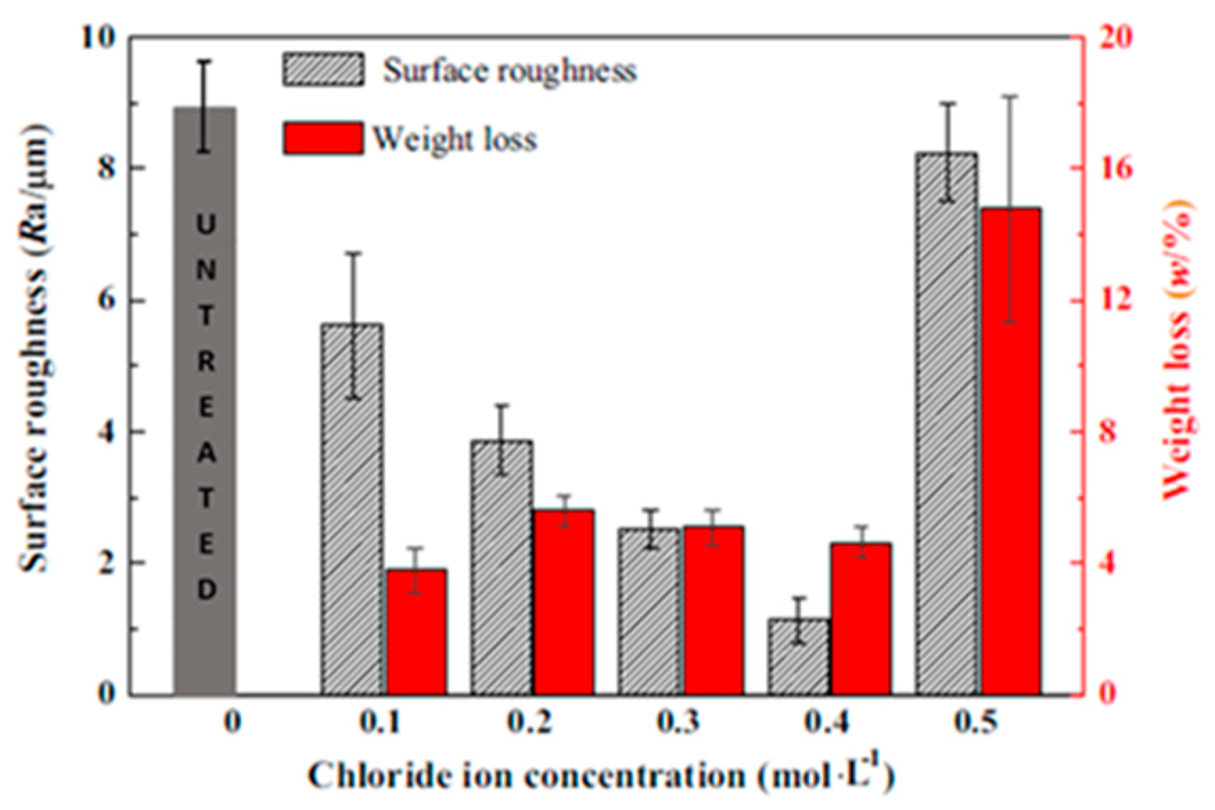
Zhang et al. [76] explored the effect of the addition of chloride ions to alcohol-based electrolytic solution on LPBF Ti6Al4V parts. No information was given about the choice of the current density applied to perform the EP treatment. Starting from a roughness of about 9 µm, the concentration of 0.4 mol/L of magnesium chloride involved the highest roughness reduction, reaching a value of 1.13 µm for a polishing time of 10 min and a weight loss of 4.63%, as depicted in Figure 7.
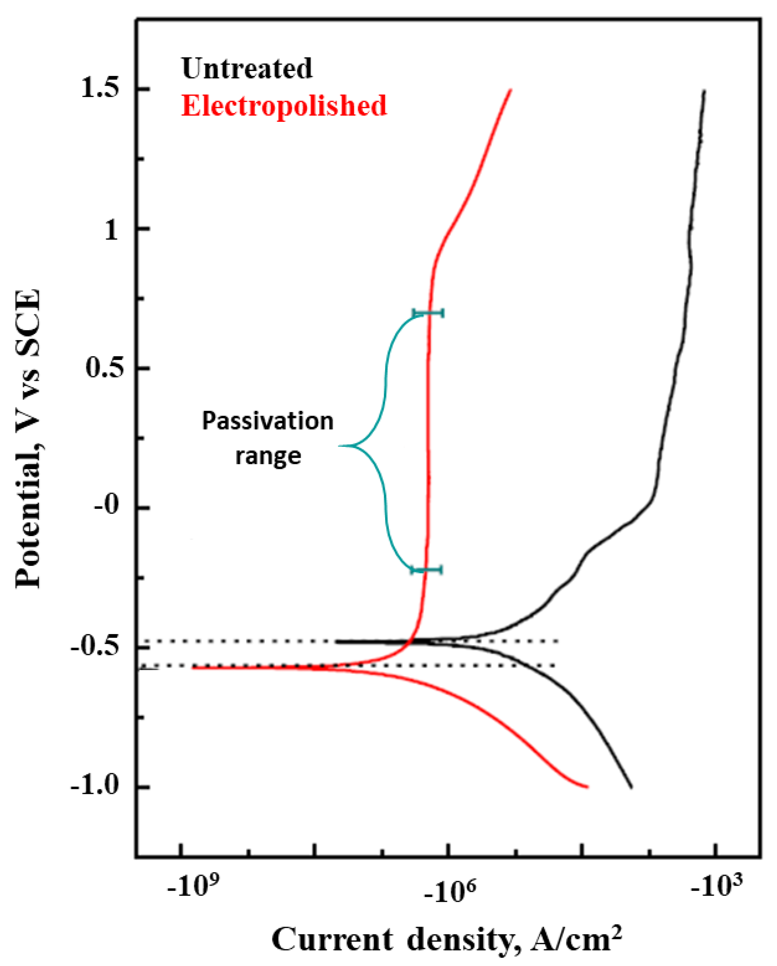
Thus, in this case, the trigger value for the best EP efficiency was represented by the electrolytic composition: below 0.4 mol/L, shadow stream tracks appeared on the surface; above 0.4 mol/L, it turned brown and uneven with deep stream tracks and pits. From XPS chemical analysis emerged the presence of TiO2 on the electropolished samples, which probably has allowed a significant improvement of the corrosion response in the simulated body fluid, as reported in Figure 8. The electropolished sample presented a current density of one order of magnitude lower than the untreated one, but also a larger passivation range. The best electrochemical properties of the EP sample have also been confirmed by electrochemical impedance spectroscopy (EIS) analysis.
The authors claimed that the presence of chloride involved the formation of the stick yellow high viscosity intermediate products of TiCl4 on the anode surface, whose thickness must be maintained at a proper value to allow the mass transfer process of the EP. Therefore, it is necessary to decompose these products with the addition of ethanol [77] and remove the same by stirring the solution to provide the formation of a TiO2 oxide layer evenly distributed on it, as also reported by Sun [78].
Yang et al. [79] also studied the efficiency of the EP, which carried out on EBM-manufactured Ti6Al4V parts using a solution composed of ethyl alcohol, isopropyl alcohol, zinc chloride, and aluminium. They studied different EP processing conditions to optimise the electrolyte flow control. A fixed electrolyte flow and a best electrode distance of about 8 mm, and a full factorial experimental design with three input parameters, voltage, temperature, and polishing time, have been adopted (Table 2).
Beyond roughness measurements, conducted through a profilometer, a preliminary fatigue test was performed. Among the investigated variables, the most relevant one appeared to be the polishing time. The initial roughness was 30–40 μm. After a 20 min treatment, an uneven polishing was observed despite the improved electrolyte flow control, with a roughness of 5–15 μm. The combination of 80 V–26.7 °C and 60 V–37.8 °C involved the best surface quality and the fatigue results, improving the fatigue life of the finished product by over 300%.
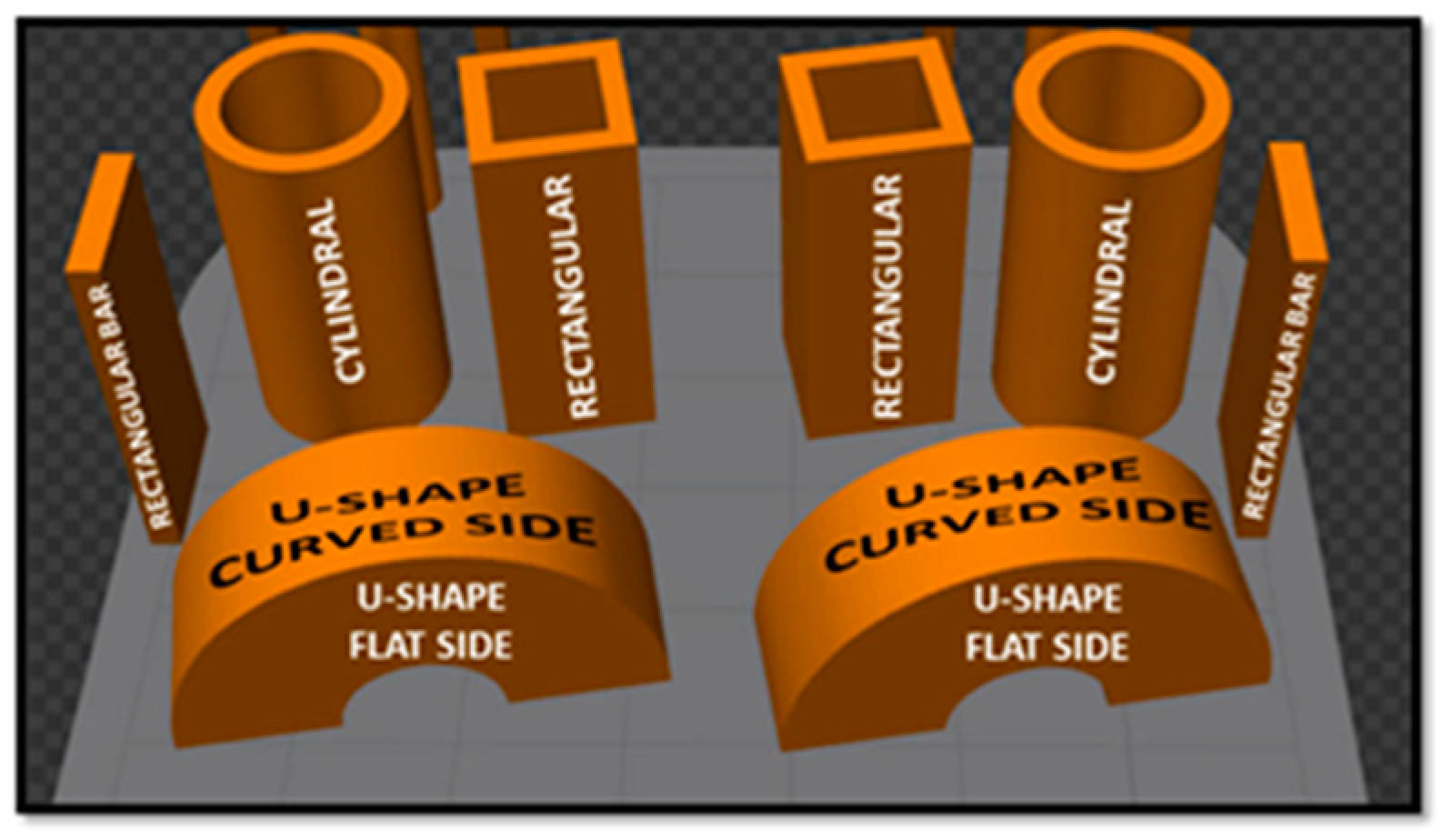
Fayazfar et al. [80] investigated the green EP on complex LPBF Ti6Al4V parts with internal channels and various geometries (see Figure 9), performing an intermittent polishing. The electrolyte consisted of an eco-friendly, non-aqueous recipe including ethanol, isopropyl alcohol, anhydrous aluminium, and anhydrous zinc chloride. The EP treatment, carried out at room temperature, at 70 V and 500 rpm, was conducted for 20 s, followed by a 10 s break of zero potential which was repeated for the entire time cycle. The EP times were selected in increasing order starting from 60 s up to 700 s (i.e., 0, 60, 100, 150, 250, 350, 450, 550, and 700 s). Customised counter-electrodes have been employed.
After 350 s, when a smoothly polished surface appeared, a reduction of 70% of as-built roughness (12 µm), leading to 11% thickness reduction, was observed for the rectangular bar geometry. These preliminary results were then extended to electropolish the complexly shaped ones, with internal channels. Regarding the U-shape, a polishing time of 800 s was adopted, having an initial roughness of about 32 µm.
As reported in Figure 10, the rectangular, cylinder, and U-shaped flat samples showed after the polishing treatment a significant decrease in the internal surface roughness of 77%, 65%, 71%, respectively, with a corresponding thickness loss of 7%, 5%, 12%. The U-shape curved sample presented the highest initial roughness, being the so-called down skin of the parts, due to the different laser–material interaction phenomena. The EP treatment allowed a reduction of roughness and thickness of 37% and 8%, respectively. The internal surface roughness after electropolishing in the cylindrical tube was lower than the rectangular parts due to the greater ease with which electrolytic solution can flow in a cylinder. Although the SEM images confirmed the removal of the stripes and partially adhered particles from the inner surfaces after polishing, some rippled texture was noticeable, highlighting the needs of using different EP approaches and/or further optimisation of the surface treatment parameters.
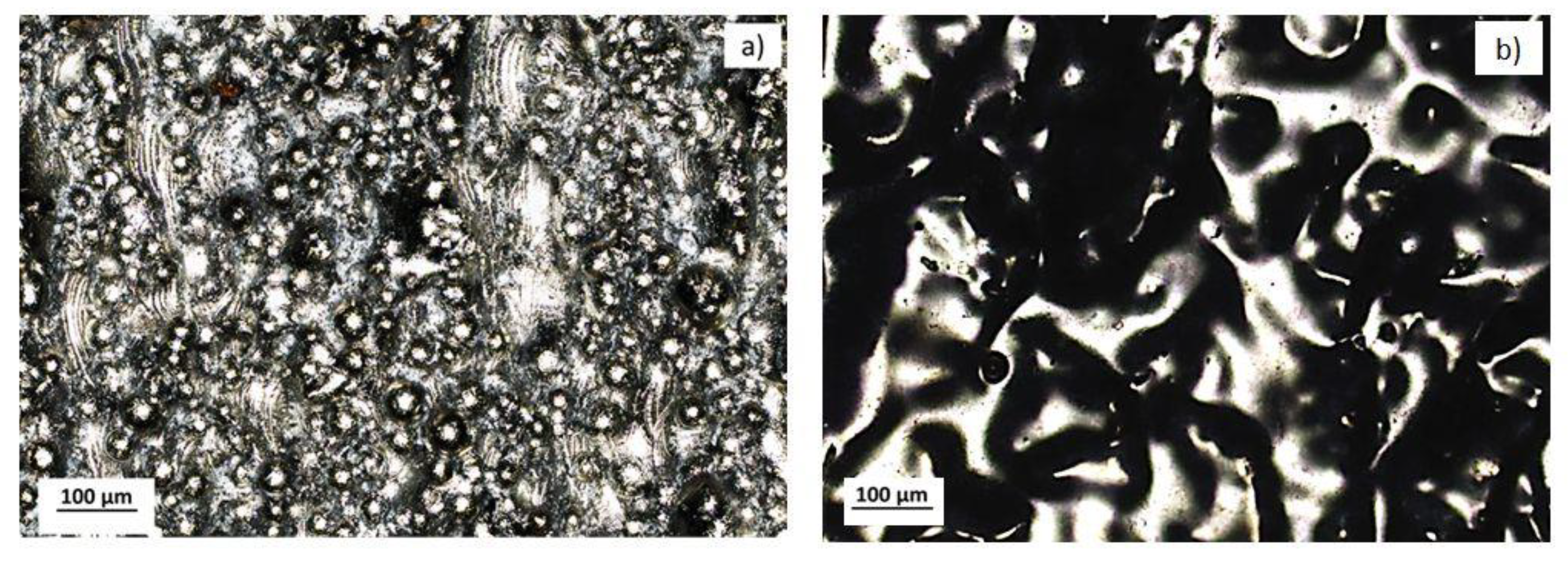
Acquesta and Monetta [25], in a preliminary paper, reported the roughness measurement results of the EP treatment carried out using an eco-friendly, ethylene-glycol-based solution based on Ti6Al4V plate parts produced by EBM technique. The potential–current density curve (reported in Figure 11) defined the potential value at which the electropolishing treatment was performed, i.e., at 25 V, which is the last potential value of the electropolishing range, before the rapid increase of the current density, as suggested by the literature.
In this study, surface roughness parameters have been considered. A significant reduction of the roughness has been found, from a Sa value of about 53 µm of the as-built sample to about 10 µm after the EP treatment. The authors considered beyond the Sq, Sku, and Ssk parameters, and further, the Sdr and Sdq ones, because they highlighted the efficiency of the treatment. The Sdr parameter, representative of the developed interfacial area ratio, was reduced from 124.86% to 18.50%. The Sdq parameter, the root mean square value of the ordinate slope, was reduced from 2.82 to 0.88, suggesting the smoothing of the surface. The duration of the EP treatment involved an important reduction of the initial roughness, but, as depicted in Figure 12b, additional duration time or an optimisation of the process parameters could be required for a mirror-like finishing.

5.2. Stainless Steel

Rotty et al. [81] investigated the electropolishing behaviour of cast (Cast) and laser-based additively manufactured (ALM) parts in three different DES solutions: choline chloride and urea (ChCl-Urea); choline chloride and ethylene glycol (ChCl-EG); and choline chloride and malonic acid mixture (ChCl-MA), prepared at the molar ratio of 1:1. The samples were previously ground with silicon carbide (SiC) paper to reduce the roughness at 200 nm. An interesting technique was used to observe the evolution of surface roughness during the EP: the in situ liquid atomic force microscopic (AFM) [82]. The DES, being less corrosive than acidic media, makes it possible to follow the electropolishing process live. Finally, the corrosion resistance was evaluated by linear sweep voltammetry (LSV) and chronopotentiometry tests in 3% by wt. sodium chloride at room temperature. The EP potential range was identified through the anodic polarisation scan, whose curves are shown in Figure 13, performed in the various DES combinations at a temperature of 70 °C with a rotational speed of 500 rpm. The samples before the EP treatment were mechanically ground to obtain an Ra of 200 nm.
The potential–current density curves exhibited the classical trend described by Jacquet when the ChCl-EG was used, highlighting the difference between the cast and the additive manufactured parts. The latter presented a narrower EP range and a higher current density compared to the cast counterpart. The other two DES solutions turned out to be inappropriate for the EP of 316 L components. It is well known that the EP can be performed at all the potential values inside the range indicated by the constant current density; thus, after identifying the suitable solvent, the authors carried out the EP treatment for 20 min at specific potential values individuated with a number from 1 to 4 or 5 on the potential–current density curve, i.e., 0.5, 1, 2.6, 3.9, and 4.5 V vs. SCE for a Cast sample and 0.5, 1, 1.7, 3.1, and 4 V vs. SCE for an ALM sample. The SEM observations and roughness measurements have shown for both samples a strongly attacked surface with a preferential dissolution at very low potentials: a smoother appearance in the EP range and a flawed surface when the potential falls in the oxygen evolution region. The optimal potential was about 3 V vs. SCE, which involved a final surface roughness of 2 nm. The in situ AFM analysis was established as being 300 s, the time for a diffusion-limiting mechanism to take place. The corrosion properties of a sample electropolished in the DES solution were evaluated through potentiodynamic polarisation curves shown in Figure 14 and compared with the ones obtained in acid media. The ALM sample presented a greater extension of the passivity range already before EP treatment. The use of DES improved the corrosion potential.
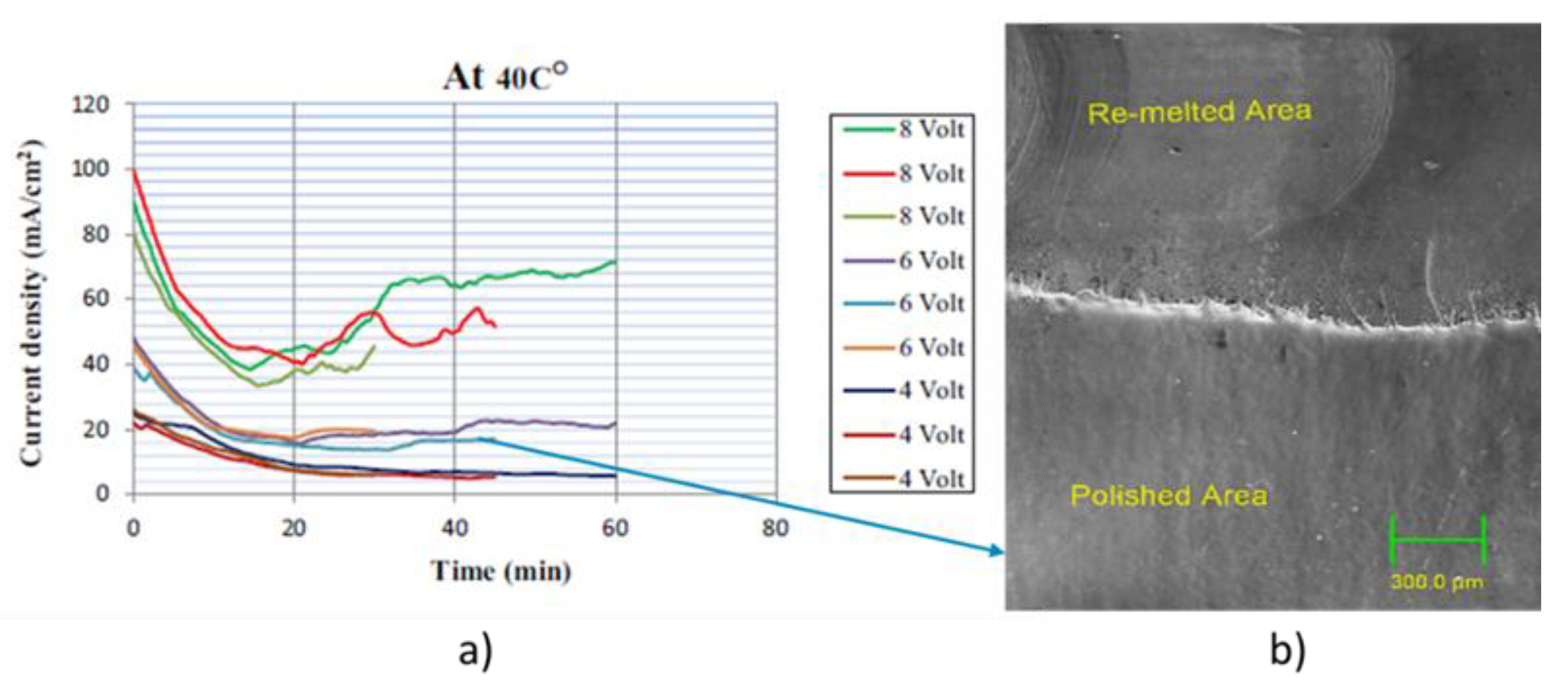
Alrbaey et al. [83] studied the electropolishing treatment of 316 L stainless-steel obtained through selective laser melting (SLM) additive technologies, using the same solution used by Abbott [65], i.e., a mixture of choline chloride (ChCl) and ethylene glycol (EG) in a weight ratio of 1:2, adding 5 and 10% oxalic acid to improve its conductivity and viscosity. Before the electropolishing treatment, the samples were remelted on the top surface, using optimal parameters of the LPBF technique used to fabricate them, to reduce the as-built roughness from 12 µm to 1.5 µm. The authors adopted a full factorial experimental 3 × 3 design, i.e., three parameters for three levels. In particular, the parameters were: potential, treatment duration, and temperature. The levels were: 4, 6, or 8 V for potential; 30, 45, or 60 min for the treatment duration; 20, 40, or 60 °C for the temperature (Table 3).
The addition of oxalic acid improved the viscosity and the conductivity in all ranges of temperature tested. The best result from a roughness point of view was exhibited for the EP treatment carried out, applying a voltage of 6 V at a temperature of 40 °C for a duration of 60 min, in which low densities of currents between 10 and 20 mA/cm2 were recorded, as depicted in Figure 15. The surface roughness obtained under these conditions was found to be equal to 0.34 µm. In contrast, this led to an excessive reduction in thickness exceeding the required dimensional tolerances, so the authors suggested performing the EP in a voltage range of 4–6 V with a duration of the process between 30 and 60 minutes, keeping the temperature at 40 °C. Beyond these ranges, the EP treatment involved pitting phenomena.
The chemical analysis demonstrated a preferential removal of iron and nickel atoms from the anode lattice, leaving the surface rich in chromium, which may be beneficial in some applications, especially where corrosion resistance, friction, and mechanical strength are of primary importance. The EP treatment of the re-melted samples involved an improvement in fatigue life at low stresses (about 570 MPa) of approximately 20%.

5.3. Ni-Based Alloy

Yang et al. [84] investigated the effects of temperature, voltage, electrode spacing, and flow rate on the surface roughness using a solution composed of ethyl alcohol, isopropyl alcohol, AlCl3, and ZnCl2. A 52 full factorial experimental setup has been adopted, varying the parameters of temperature, electrode spacing, flow rate, voltage, and flow-splitter configuration. Each one assumed two values, as reported in Table 4.
In addition, the fluid flow simulations have been carried out. The initial roughness of the as-built samples was 7.90 ± 0.3 µm, which was reduced in a range of 1.8–4 µm after a combination of all possible factors. The use of a split configuration influenced the surface quality, but not as significant as expected and even demonstrated by simulation tests.
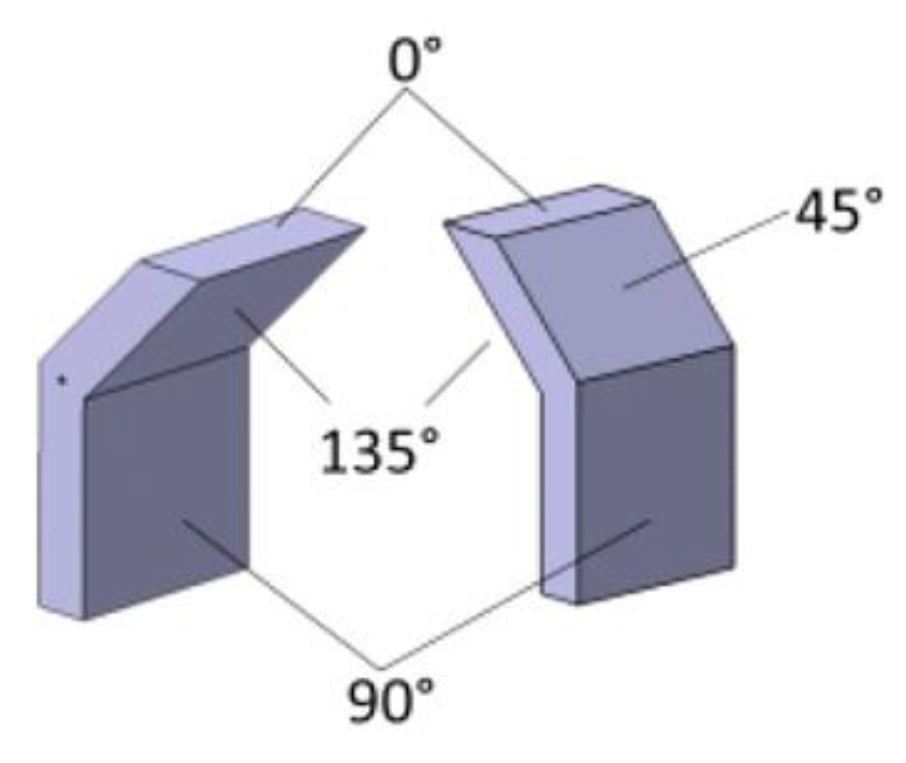
Mohammadian et al. [85] studied the efficiency of the EP carried out in the DES solution composed of choline chloride and ethylene glycol of LPBF IN625 components with a V-shape containing multiple surfaces, differently oriented with respect to the building platform (Figure 16). The influence of the temperature was investigated. In addition to the roughness measurements, mass loss and thickness reduction have been evaluated.
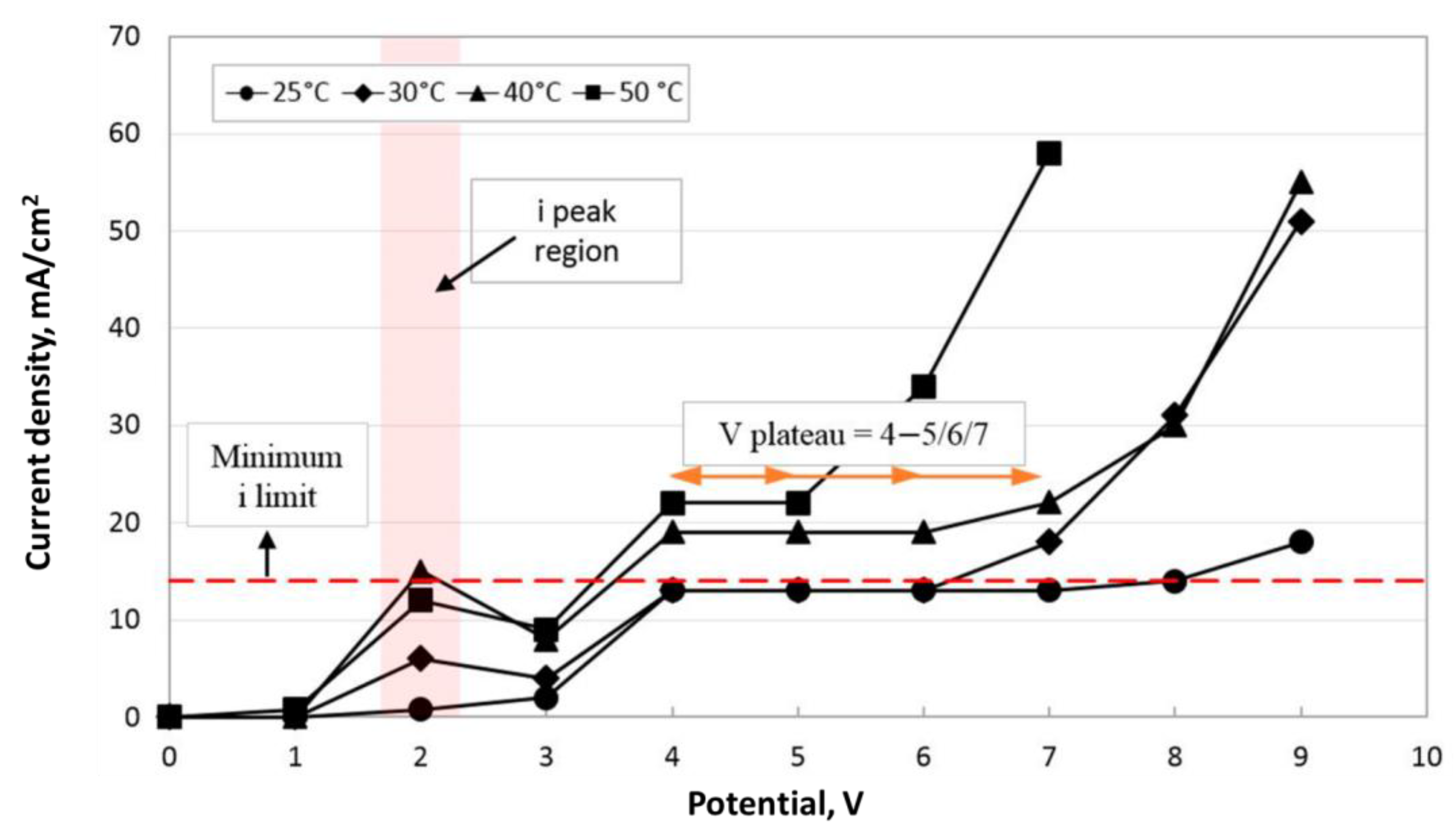
The EP working condition has been investigated early to individuate the optimal potential for the different temperatures (Figure 17), stirring the solution at 160 rpm. Generally, when the temperature increased, the current density corresponding to the plateau increased, but the range of potentials narrowed. In contrast to the EP performed in an acid-based solution, in which the potential value to obtain the best surface quality was the highest of the potential plateau, the authors found as optimal conditions the lowest potentials of the EP range, 4 V at 50 °C and 5 V at 40 °C, with a current density of 12–20 mA/cm2. No relevant difference has been found between the curves recorded at 25 and 30 °C. In addition, no significant improvement of the roughness has been observed at low temperatures.
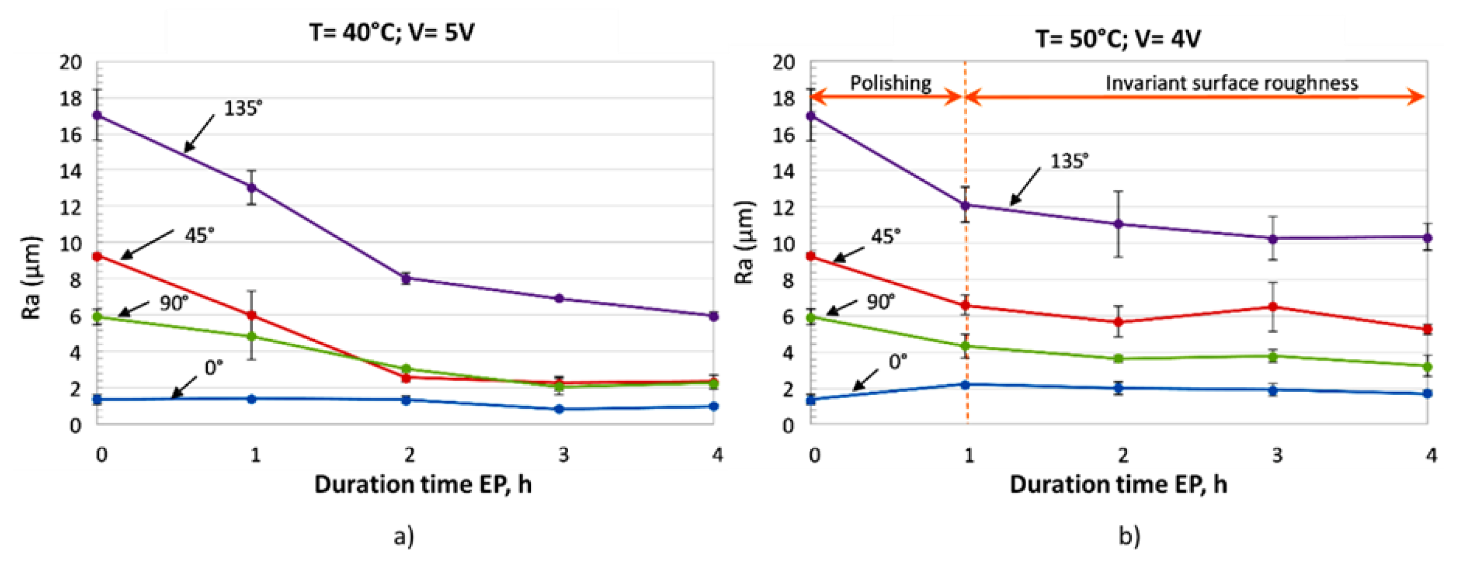
The samples, as expected, exhibited a large scattering of initial roughness values according to the building direction, from about 1.4 (0°) to 17 µm (135°), as shown in Figure 18.
The condition of 40 °C and 5 V of potential allowed a more significant roughness reduction just after 2 h of treatment compared to the process performed at 50 °C and 4 V. However, four hours were needed to reduce the roughness below 6.3 µm, which was the aim of the authors. When the EP treatment was performed at higher temperature but lower potential, no relevant surface roughness reduction was observed after the first hour. The total mass loss evolution over time was linear, resulting in almost 6% of mass reduction after 4 h of EP. The thickness reduction was significant after 2 h for all of the surface, in particular for the highest roughness surface, i.e., 135°. However, the current efficiency, expressed as the ratio of the actual mass loss of the anode to the theoretical mass liberated according to Faraday’s law, was 90%, which was higher than that obtained by the same authors using an acid-based electrolytic solution.
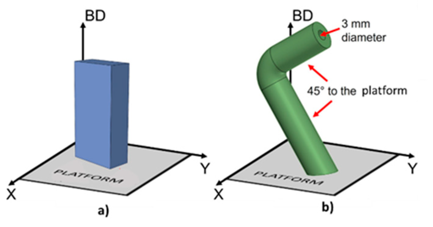
Jiang et al. [86] investigated the EP treatment of LPBF-produced nickel-based alloy (Hastelloy (HX)) parts with a flat plate shape and an angled cylindrical porous tube (see Figure 19) in a DES solution, with an ethylene glycol and choline chloride base, at 70 °C and stirred at 400 rpm. This alloy is most used in chemical and petrochemical industries.
The initial studies were carried out on the flat plate sample, to subsequently extend them on the complexly shaped parts. An optimal current density of 19.5 mA/cm2 was identified from the current–potential curve. The influence of different duration times (from 1 to 5 min) of EP were studied. Under these treatment conditions, the initial roughness of the as-built sample of 12 µm was reduced to 1.2 µm, as shown in Figure 20b. Regarding the material removal rate, evaluated as the weight reduction rate, the initial weight of about 8 g was reduced by 1.7% after 5 min.
The complex shape intensifies the already high roughness that characterizes the additively manufactured products, since in addition to the attached partially melted particles and balling effect, there is the well-known “stair-step effect”, which arises when inclined surfaces are built. This effect involves a so-called down-skin (DS) rougher than the so-called up-skin (UP), as exhibited in Figure 20, on the top (b) and bottom (d) zones of the cylindric tube. The SEM images revealed that after 5 min of EP, during which the electrolyte was pumped through the internal channel through a peristaltic pump, the UP of the as-built sample at the top and bottom zone was reduced of 80%, more than the DS.
The authors reported that the chemical analysis (here not reported) performed using the SEM-EDS line scanning highlighted the presence of cellular dendritic structures, whose boundary protrusions were composed mainly of molybdenum, whilst the centre of the cell was composed of iron and nickel, which resulted in being more favourably dissolved by DES. From a hardness test, a slight decrease of about 30 HV appeared after the EP treatment, probably due to the release of surface residual stress during the treatment. The electrochemical properties have been investigated in a natural aerated 1 M NaCl solution at room temperature. The electrochemical polishing improved the corrosion potential, Ecorr, from −0.39 VSCE for the as-built sample to −0.20 V vs. SCE. In addition, a reduced corrosion current density and a more stable passivation range were recorded. The electrochemical impedance spectroscopy confirmed the best corrosion resistance of the EP sample, since the polarisation resistance has increased about six times than the as-built sample.
A summary of the electrochemical conditions adopted by the different studies which have adopted a green approach is reported in Table 5.

6. Conclusions

Additive technologies undoubtedly have numerous advantages over conventional ones. It remains to be solved that one of their most important limitations is the surface finish. Among the numerous post-processing surface treatments present in the literature, a valid alternative is represented by electropolishing which, unfortunately, is often carried out with dangerous and difficult-to-dispose-of chemical substances, as amply demonstrated by the current reference literature.
An attractive alternative could be the use of green solutions but, to date, only a few studies are available on electropolishing treatments that adopt these new formulations. Among these, deep eutectic solvents seem to be the favourites, due to their stability in air and humidity, biodegradability, eco-compatibility, relative cheapness, and non-flammability. DESs are simple to prepare, with no need to add more solvent or perform additional purification steps. Further, their use seems to also improve the mechanical and electrochemical properties. Promising results already obtained for both simple and complex geometries have been reported in this review.

7. Future Scope and Development

The future researchers should be addressed on:
  • The optimisation of the EP treatment parameters to reduce the energy consumption.
  • The possibility of investigating the effectiveness of the EP treatment in NaDES-based electrolytes.
  • The investigation of the EP treatment using green electrolytes on other kind of alloys, such as the most used aluminium alloy, AlSi10Mg.
  • The possibility of reusing the exhaust electrolytic solution.
  • The possibility of developing new and renewable DESs solutions.
  • The AI and machine learning approaches, as applied to the optimisation process of AM technologies, could help to also optimise the post-processing treatment.

Author Contributions

Conceptualisation, A.A. and T.M.; methodology, A.A.; investigation, A.A.; writing—original draft preparation, A.A.; writing—review and editing, T.M.; supervision, T.M. All authors have read and agreed to the published version of the manuscript.

Funding

This research received no external funding.

Institutional Review Board Statement

Not applicable.

Data Availability Statement

No new data were created in this study.

Conflicts of Interest

The authors declare no conflict of interest.

References

  1. Dilberoglu, U.M.; Gharehpapagh, B.; Yaman, U.; Dolen, M. The Role of Additive Manufacturing in the Era of Industry 4.0. Procedia Manuf. 2017, 11, 545–554. [Google Scholar] [CrossRef]
  2. Grad, M.; Nadammal, N.; Schultheiss, U.; Lulla, P.; Noster, U. An Integrative Experimental Approach to Design Optimization and Removal Strategies of Supporting Structures Used during L-PBF of SS316L Aortic Stents. Appl. Sci. 2021, 11, 9176. [Google Scholar] [CrossRef]
  3. Cooke, S.; Ahmadi, K.; Willerth, S.; Herring, R. Metal additive manufacturing: Technology, metallurgy and modelling. J. Manuf. Process. 2020, 57, 978–1003. [Google Scholar] [CrossRef]
  4. Herzog, D.; Seyda, V.; Wycisk, E.; Emmelmann, C. Additive manufacturing of metals. Acta Mater. 2016, 117, 371–392. [Google Scholar] [CrossRef]
  5. Hufenbach, J.; Sander, J.; Kochta, F.; Pilz, S.; Voss, A.; Kühn, U.; Gebert, A. Effect of Selective Laser Melting on Microstructure, Mechanical, and Corrosion Properties of Biodegradable FeMnCS for Implant Applications. Adv. Eng. Mater. 2020, 22, 2000182. [Google Scholar] [CrossRef]
  6. Acquesta, A.; Monetta, T. As-Built EBM and DMLS Ti-6Al-4V Parts: Topography–Corrosion Resistance Relationship in a Simulated Body Fluid. Metals 2020, 10, 1015. [Google Scholar] [CrossRef]
  7. Kim, U.S.; Park, J.W. High-Quality Surface Finishing of Industrial Three-Dimensional Metal Additive Manufacturing Using Electrochemical Polishing. Int. J. Precis. Eng. Manuf. Technol. 2019, 6, 11–21. [Google Scholar] [CrossRef]
  8. Acquesta, A.; Monetta, T. The Electropolishing of Additively Manufactured Parts in Titanium: State of the Art. Adv. Eng. Mater. 2021, 23, 2100545. [Google Scholar] [CrossRef]
  9. Kim, F.H.; Moylan, S.P. Literature Review of Metal Additive Manufacturing Defects; NIST Advanced Manufacturing Series 100-16; US Department of Commerce, National Institute of Standards and Technology: Gaithersburg, MD, USA, 2018. [Google Scholar] [CrossRef]
  10. Santecchia, E.; Spigarelli, S.; Cabibbo, M. Material Reuse in Laser Powder Bed Fusion: Side Effects of the Laser—Metal Powder Interaction. Metals 2020, 10, 341. [Google Scholar] [CrossRef] [Green Version]
  11. Pal, R.; Basak, A. Linking Powder Properties, Printing Parameters, Post-Processing Methods, and Fatigue Properties in Additive Manufacturing of AlSi10Mg. Alloys 2022, 1, 149–179. [Google Scholar] [CrossRef]
  12. Denti, L.; Sola, A. On the Effectiveness of Different Surface Finishing Techniques on A357.0 Parts Produced by Laser-Based Powder Bed Fusion: Surface Roughness and Fatigue Strength. Metals 2019, 9, 1284. [Google Scholar] [CrossRef] [Green Version]
  13. Avanzini, A.; Battini, D.; Gelfi, M.; Girelli, L.; Petrogalli, C.; Pola, A.; Tocci, M. Investigation on fatigue strength of sand-blasted DMLS-AlSi10Mg alloy. Procedia Struct. Integr. 2019, 18, 119–128. [Google Scholar] [CrossRef]
  14. Walczak, M.; Szala, M. Effect of shot peening on the surface properties, corrosion and wear performance of 17-4PH steel produced by DMLS additive manufacturing. Arch. Civ. Mech. Eng. 2021, 21, 157. [Google Scholar] [CrossRef]
  15. Subramaniyan, A.K.; Reddy, A.S.; Mathias, S.; Shrivastava, A.; Raghupatruni, P. Influence of post-processing techniques on the microstructure, properties and surface integrity of Al Si Mg alloy processed by laser powder bed fusion technique. Surf. Coat. Technol. 2021, 425, 127679. [Google Scholar] [CrossRef]
  16. Peng, C.; Fu, Y.; Wei, H.; Li, S.; Wang, X.; Gao, H. Study on Improvement of Surface Roughness and Induced Residual Stress for Additively Manufactured Metal Parts by Abrasive Flow Machining. Procedia CIRP 2018, 71, 386–389. [Google Scholar] [CrossRef]
  17. Yasa, E.; Deckers, J.; Kruth, J.P. The investigation of the influence of laser re-melting on density, surface quality and microstructure of selective laser melting parts. Rapid Prototyp. J. 2011, 17, 312–327. [Google Scholar] [CrossRef]
  18. Tyagi, P.; Goulet, T.; Riso, C.; Stephenson, R.; Chuenprateep, N.; Schlitzer, J.; Benton, C.; Garcia-Moreno, F. Reducing the roughness of internal surface of an additive manufacturing produced 316 steel component by chempolishing and electropolishing. Addit. Manuf. 2019, 25, 32–38. [Google Scholar] [CrossRef] [Green Version]
  19. Charazińska, S.; Lochyński, P.; Markiewicz, M.; Stolte, S.; Burszta-Adamiak, E. Treatment of electropolishing industrial wastewater and its impact on the immobilisation of Daphnia magna. Environ. Res. 2022, 212, 113438. [Google Scholar] [CrossRef] [PubMed]
  20. Singh, J.; Singh, G.; Pandey, P.M. Electric Discharge Machining Using Rapid Manufactured Complex Shape Copper Electrode with Cryogenic Cooling Channel. Proc. Inst. Mech. Eng. Part B J. Eng. Manuf. 2021, 235, 173–185. [Google Scholar] [CrossRef]
  21. Smith, E.L.; Abbott, A.P.; Ryder, K.S. Deep Eutectic Solvents (DESs) and Their Applications. Chem. Rev. 2014, 114, 11060–11082. [Google Scholar] [CrossRef] [Green Version]
  22. Chaghazardi, Z.; Wüthrich, R. Review—Electropolishing of Additive Manufactured Metal Parts. J. Electrochem. Soc. 2022, 169, 043510. [Google Scholar] [CrossRef]
  23. Basha, M.; Jain, V.; Sankar, M. State of the art on chemical and electrochemical based finishing processes for additive manufactured features. Addit. Manuf. 2022, 58, 103028. [Google Scholar] [CrossRef]
  24. Landolt, D. Fundamental aspects of electropolishing. Electrochim. Acta 1987, 32, 1–11. [Google Scholar] [CrossRef]
  25. Acquesta, A.; Monetta, T. Electropolishing in Ecofriendly Solution of Ti6Al4V Parts Produced by Electron Beam Melting. Metall. Ital. 2021, 113, 74–80. [Google Scholar]
  26. Jacquet, P.A. Electrolytic and chemical polishing. Met. Rev. 1956, 1, 157–238. [Google Scholar] [CrossRef]
  27. Hoar, T.P.; Mowat, J.A.S. Mechanism of Electropolishing. Nature 1950, 165, 64–65. [Google Scholar] [CrossRef]
  28. Elmore, W.C. Electrolytic Polishing. J. Appl. Phys. 1939, 10, 724–727. [Google Scholar] [CrossRef]
  29. Datta, M.; Vega, L.; Romankiw, L.; Duby, P. Mass transport effects during electropolishing of iron in phosphoric-sulfuric acid. Electrochim. Acta 1992, 37, 2469–2475. [Google Scholar] [CrossRef]
  30. Neelakantan, L.; Pareek, A.; Hassel, A.W. Electro-dissolution of 30Nb–Ti alloys in methanolic sulfuric acid—Optimal conditions for electropolishing. Electrochim. Acta 2011, 56, 6678–6682. [Google Scholar] [CrossRef]
  31. Grimm, R.-D.; Landolt, D. Salt films formed during mass transport controlled dissolution of iron-chromium alloys in concentrated chloride media. Corros. Sci. 1994, 36, 1847–1868. [Google Scholar] [CrossRef]
  32. Matlosz, M.; Magaino, S.; Landolt, D. Impedance Analysis of a Model Mechanism for Acceptor-Limited Electropolishing. J. Electrochem. Soc. 1994, 141, 410–418. [Google Scholar] [CrossRef]
  33. Monetta, T.; Acquesta, A.; Bellucci, F. Evaluation of Roughness and Electrochemical Behavior of Titanium in Biological Environment. Metall. Ital. 2014, 106, 13–21. [Google Scholar]
  34. Townsend, A.; Senin, N.; Blunt, L.; Leach, R.K.; Taylor, J.S. Surface texture metrology for metal additive manufacturing: A review. Precis. Eng. 2016, 46, 34–47. [Google Scholar] [CrossRef] [Green Version]
  35. Kumar, S.; Kushwaha, A.; Nagesha, B.K.; Barad, S. Hybrid surface characterisation of intra thin-walled Ti6Al4V surfaces produced by laser powder bed fusion technology. Surf. Topogr. Metrol. Prop. 2022, 10, 015006. [Google Scholar] [CrossRef]
  36. Grimm, T.; Witt, G.; Wiora, G. Characterization of Additive Manufactured Surfaces with Confocal Microscopy. Surf. Topogr. Metrol. Prop. 2014, 3, 139–144. [Google Scholar]
  37. Zanini, F.; Pagani, L.; Scott, P.; Savio, E.; Carmignato, S. Measurement of Additively Manufactured Surfaces with Re-Entrant Features by X-Ray Computed Tomography. In Proceedings of the ASPE/Euspen Conference: Advancing Precision in Additive Manufacturing, Leuven, Belgium, 7–9 February 2017. [Google Scholar]
  38. Moylan, S. Progress toward Standardized Additive Manufacturing Test Artifacts. In Proceedings of the ASPE 2015 Spring Topical Meeting: Achieving Precision Tolerances in Additive Manufacturing, Raleigh, NC, USA, 26–29 April 2015; pp. 100–105. [Google Scholar]
  39. Nakar, D.; Harel, D.; Hirsch, B. Electropolishing effect on roughness metrics of ground stainless steel: A length scale study. Surf. Topogr. Metrol. Prop. 2017, 6, 015003. [Google Scholar] [CrossRef]
  40. Urlea, V.; Brailovski, V. Electropolishing and electropolishing-related allowances for powder bed selectively laser-melted Ti-6Al-4V alloy components. J. Mater. Process. Technol. 2017, 242, 1–11. [Google Scholar] [CrossRef]
  41. Zhang, Y. Electropolishing Mechanism of Ti-6Al-4V Alloy Fabricated by Selective Laser Melting. Int. J. Electrochem. Sci. 2018, 13, 4792–4807. [Google Scholar] [CrossRef]
  42. Wu, Y.-C.; Kuo, C.-N.; Chung, Y.-C.; Ng, C.-H.; Huang, J.C. Effects of Electropolishing on Mechanical Properties and Bio-Corrosion of Ti6Al4V Fabricated by Electron Beam Melting Additive Manufacturing. Materials 2019, 12, 1466. [Google Scholar] [CrossRef] [PubMed] [Green Version]
  43. Pyka, G.; Burakowski, A.; Kerckhofs, G.; Moesen, M.; Van Bael, S.; Schrooten, J.; Wevers, M. Surface Modification of Ti6Al4V Open Porous Structures Produced by Additive Manufacturing. Adv. Eng. Mater. 2012, 14, 363–370. [Google Scholar] [CrossRef]
  44. Langi, E.; Zhao, L.; Jamshidi, P.; Attallah, M.; Silberschmidt, V.; Willcock, H.; Vogt, F. A comparative study of microstructures and nanomechanical properties of additively manufactured and commercial metallic stents. Mater. Today Commun. 2022, 31, 103372. [Google Scholar] [CrossRef]
  45. Rotty, C.; Mandroyan, A.; Doche, M.-L.; Hihn, J. Electropolishing of CuZn brasses and 316L stainless steels: Influence of alloy composition or preparation process (ALM vs. standard method). Surf. Coat. Technol. 2016, 307, 125–135. [Google Scholar] [CrossRef]
  46. Jain, S.; Corliss, M.; Tai, B.; Hung, W.N. Electrochemical polishing of selective laser melted Inconel 718. Procedia Manuf. 2019, 34, 239–246. [Google Scholar] [CrossRef]
  47. Baicheng, Z.; Xiaohua, L.; Jiaming, B.; Junfeng, G.; Pan, W.; Chen-Nan, S.; Muiling, N.; Guojun, Q.; Jun, W. Study of selective laser melting (SLM) Inconel 718 part surface improvement by electrochemical polishing. Mater. Des. 2017, 116, 531–537. [Google Scholar] [CrossRef]
  48. Urlea, V.; Brailovski, V. Electropolishing and electropolishing-related allowances for IN625 alloy components fabricated by laser powder-bed fusion. Int. J. Adv. Manuf. Technol. 2017, 92, 4487–4499. [Google Scholar] [CrossRef]
  49. Liu, H.; Ye, M.; Ye, Z.; Wang, L.; Wang, G.; Shen, X.; Xu, P.; Wang, C. High-quality surface smoothening of laser powder bed fusion additive manufacturing AlSi10Mg via intermittent electrochemical polishing. Surf. Coat. Technol. 2022, 443, 128608. [Google Scholar] [CrossRef]
  50. Shrivastava, A.; Mathias, S.; Prasad, R.; Kumar, S. Investigation on Electrolytically Polished AlSi10Mg Alloy Processed via Selective Laser Melting/3D Printing Route. Proc. Inst. Mech. Eng. Part L J. Mater. Des. Appl. 2020. [Google Scholar] [CrossRef]
  51. Demir, A.G.; Previtali, B. Additive manufacturing of cardiovascular CoCr stents by selective laser melting. Mater. Des. 2017, 119, 338–350. [Google Scholar] [CrossRef] [Green Version]
  52. Abbott, A.P.; Boothby, D.; Capper, G.; Davies, D.L.; Rasheed, R.K. Deep Eutectic Solvents Formed between Choline Chloride and Carboxylic Acids: Versatile Alternatives to Ionic Liquids. J. Am. Chem. Soc. 2004, 126, 9142–9147. [Google Scholar] [CrossRef]
  53. Hansen, B.B.; Spittle, S.; Chen, B.; Poe, D.; Zhang, Y.; Klein, J.M.; Horton, A.; Adhikari, L.; Zelovich, T.; Doherty, B.W.; et al. Deep Eutectic Solvents: A Review of Fundamentals and Applications. Chem. Rev. 2020, 121, 1232–1285. [Google Scholar] [CrossRef]
  54. Abbott, A.P.; Capper, G.; Davies, D.L.; Rasheed, R.K.; Tambyrajah, V. Novel solvent properties of choline chloride/urea mixtures. Chem. Commun. 2002, 39, 70–71. [Google Scholar] [CrossRef] [Green Version]
  55. Bezerra-Neto, J.R.; Sousa, N.G.; dos Santos, L.P.M.; Correia, A.N.; de Lima-Neto, P. The effect of water on the physicochemical properties of an ethylene glycol and choline chloride mixture containing Cu2+ ions: Electrochemical results and dynamic molecular simulation approach. Phys. Chem. Chem. Phys. 2018, 20, 9321–9327. [Google Scholar] [CrossRef] [PubMed]
  56. Figueiredo, M.; Gomes, C.; Costa, R.; Martins, A.; Pereira, C.M.; Silva, F. Differential capacity of a deep eutectic solvent based on choline chloride and glycerol on solid electrodes. Electrochim. Acta 2009, 54, 2630–2634. [Google Scholar] [CrossRef]
  57. Choi, Y.H.; van Spronsen, J.; Dai, Y.; Verberne, M.; Hollmann, F.; Arends, I.W.C.E.; Witkamp, G.-J.; Verpoorte, R. Are Natural Deep Eutectic Solvents the Missing Link in Understanding Cellular Metabolism and Physiology? Plant Physiol. 2011, 156, 1701–1705. [Google Scholar] [CrossRef] [Green Version]
  58. Picchio, M.L.; Minudri, D.; Mantione, D.; Criado-Gonzalez, M.; Guzmán-González, G.; Schmarsow, R.; Müller, A.J.; Tomé, L.C.; Minari, R.J.; Mecerreyes, D. Natural Deep Eutectic Solvents Based on Choline Chloride and Phenolic Compounds as Efficient Bioadhesives and Corrosion Protectors. ACS Sustain. Chem. Eng. 2022, 10, 8135–8142. [Google Scholar] [CrossRef]
  59. Li, C.; Li, D.; Zou, S.; Li, Z.; Yin, J.; Wang, A.; Cui, Y.; Yao, Z.; Zhao, Q. Extraction desulfurization process of fuels with ammonium-based deep eutectic solvents. Green Chem. 2013, 15, 2793–2799. [Google Scholar] [CrossRef]
  60. Oliveira, F.S.; Pereiro, A.B.; Rebelo, L.P.N.; Marrucho, I.M. Deep eutectic solvents as extraction media for azeotropic mixtures. Green Chem. 2013, 15, 1326–1330. [Google Scholar] [CrossRef]
  61. Whitehead, A.H.; Pölzler, M.; Gollas, B. Zinc Electrodeposition from a Deep Eutectic System Containing Choline Chloride and Ethylene Glycol. J. Electrochem. Soc. 2010, 157, D328–D334. [Google Scholar] [CrossRef]
  62. Shen, Y.; He, X.; Hung, F.R. Structural and Dynamical Properties of a Deep Eutectic Solvent Confined Inside a Slit Pore. J. Phys. Chem. C. 2015, 119, 24489–24500. [Google Scholar] [CrossRef]
  63. Liao, H.-G.; Jiang, Y.-X.; Zhou, Z.-Y.; Chen, S.-P.; Sun, S.-G. Shape-Controlled Synthesis of Gold Nanoparticles in Deep Eutectic Solvents for Studies of Structure-Functionality Relationships in Electrocatalysis. Angew. Chem. Int. Ed. 2008, 47, 9100–9103. [Google Scholar] [CrossRef] [PubMed] [Green Version]
  64. Abbott, A.P. Deep eutectic solvents and their application in electrochemistry. Curr. Opin. Green Sustain. Chem. 2022, 36, 100649. [Google Scholar] [CrossRef]
  65. Abbott, A.P.; Capper, G.; McKenzie, K.J.; Ryder, K.S. Voltammetric and impedance studies of the electropolishing of type 316 stainless steel in a choline chloride based ionic liquid. Electrochim. Acta 2006, 51, 4420–4425. [Google Scholar] [CrossRef]
  66. Yan, G.; Zhou, Y.; Zhao, L.; Wang, W.; Yang, Y.; Zhao, X.; Chen, Y.; Yao, X. Recycling of deep eutectic solvent for sustainable and efficient pretreatment of corncob. Ind. Crop. Prod. 2022, 183, 115005. [Google Scholar] [CrossRef]
  67. Jeong, K.M.; Lee, M.S.; Nam, M.W.; Zhao, J.; Jin, Y.; Lee, D.-K.; Kwon, S.W.; Jeong, J.H.; Lee, J. Tailoring and recycling of deep eutectic solvents as sustainable and efficient extraction media. J. Chromatogr. A 2015, 1424, 10–17. [Google Scholar] [CrossRef]
  68. Liang, X.; Fu, Y.; Chang, J. Effective separation, recovery and recycling of deep eutectic solvent after biomass fractionation with membrane-based methodology. Sep. Purif. Technol. 2019, 210, 409–416. [Google Scholar] [CrossRef]
  69. Wang, X.; Nie, Y.; Zhang, X.; Zhang, S.; Li, J. Recovery of ionic liquids from dilute aqueous solutions by electrodialysis. Desalination 2012, 285, 205–212. [Google Scholar] [CrossRef]
  70. Isci, A.; Kaltschmitt, M. Recovery and recycling of deep eutectic solvents in biomass conversions: A review. Biomass-Convers. Biorefin. 2021, 12, 197–226. [Google Scholar] [CrossRef]
  71. Hayyan, A.; Hashim, M.A.; Hayyan, M.; Mjalli, F.S.; AlNashef, I.M. A new processing route for cleaner production of biodiesel fuel using a choline chloride based deep eutectic solvent. J. Clean. Prod. 2014, 65, 246–251. [Google Scholar] [CrossRef]
  72. Kumar, A.K.; Parikh, B.S.; Pravakar, M. Natural deep eutectic solvent mediated pretreatment of rice straw: Bioanalytical characterization of lignin extract and enzymatic hydrolysis of pretreated biomass residue. Environ. Sci. Pollut. Res. 2016, 23, 9265–9275. [Google Scholar] [CrossRef]
  73. Yu, Q.; Song, Z.; Zhuang, X.; Liu, L.; Qiu, W.; Shi, J.; Wang, W.; Li, Y.; Wang, Z.; Yuan, Z. Catalytic conversion of herbal residue carbohydrates to furanic derivatives in a deep eutectic solvent accompanied by dissolution and recrystallisation of choline chloride. Cellulose 2019, 26, 8263–8277. [Google Scholar] [CrossRef]
  74. Smink, D.; Kersten, S.R.; Schuur, B. Comparing multistage liquid–liquid extraction with cold water precipitation for improvement of lignin recovery from deep eutectic solvents. Sep. Purif. Technol. 2020, 252, 117395. [Google Scholar] [CrossRef]
  75. Panić, M.; Gunjević, V.; Cravotto, G.; Redovniković, I.R. Enabling technologies for the extraction of grape-pomace anthocyanins using natural deep eutectic solvents in up-to-half-litre batches extraction of grape-pomace anthocyanins using NADES. Food Chem. 2019, 300, 125185. [Google Scholar] [CrossRef] [PubMed]
  76. Zhang, Y.; Li, J.; Che, S.; Tian, Y. Electrochemical Polishing of Additively Manufactured Ti–6Al–4V Alloy. Met. Mater. Int. 2020, 26, 783–792. [Google Scholar] [CrossRef]
  77. Ferreri, N.C.; Savage, D.J.; Knezevic, M. Non-acid, alcohol-based electropolishing enables high-quality electron backscatter diffraction characterization of titanium and its alloys: Application to pure Ti and Ti-6Al-4V. Mater. Charact. 2020, 166, 110406. [Google Scholar] [CrossRef]
  78. Sun, X.; Wei, X.; Li, Z.; Lou, D.; Wang, Y.; Liu, H. Experimental Investigation of Electropolishing in Ethylene Glycol-NaCl Electrolyte for Surface Integrity of Nitinol Cardiovascular Stents. Electrochemistry 2020, 88, 325–329. [Google Scholar] [CrossRef]
  79. Yang, L.; Wu, Y.; Lassell, A.; Zhou, B. Electropolishing of Ti6Al4V Parts Fabricated by Electron Beam Melting. In Proceedings of the Solid Freeform Fabrication 2016: Proceedings of the 26th Annual International, Austin, TX, USA, 8–10 August 2016. [Google Scholar]
  80. Fayazfar, H.; Rishmawi, I.; Vlasea, M. Electrochemical-Based Surface Enhancement of Additively Manufactured Ti-6Al-4V Complex Structures. J. Mater. Eng. Perform. 2021, 30, 2245–2255. [Google Scholar] [CrossRef]
  81. Rotty, C.; Mandroyan, A.; Doche, M.-L.; Monney, S.; Hihn, J.-Y.; Rouge, N. Electrochemical Superfinishing of Cast and ALM 316L Stainless Steels in Deep Eutectic Solvents: Surface Microroughness Evolution and Corrosion Resistance. J. Electrochem. Soc. 2019, 166, C468–C478. [Google Scholar] [CrossRef]
  82. Gao, Q.; Tsai, W.; Balke, N. In situ and operando force-based atomic force microscopy for probing local functionality in energy storage materials. Electrochem. Sci. Adv. 2021, 2, e2100038. [Google Scholar] [CrossRef]
  83. Alrbaey, K.; Wimpenny, D.I.; Al-Barzinjy, A.A.; Moroz, A. Electropolishing of Re-melted SLM Stainless Steel 316L Parts Using Deep Eutectic Solvents: 3 × 3 Full Factorial Design. J. Mater. Eng. Perform. 2016, 25, 2836–2846. [Google Scholar] [CrossRef]
  84. Yang, L.; O’Neil, C.; Wu, Y. The Use of Electropolishing Surface Treatment on IN718 Parts Fabricated by Laser Powder Bed Fusion Process. In Proceedings of the Conference: Solid Freeform Fabrication 2017: Proceedings of the 28th Annual International, Austin, TX, USA, 7–9 August 2017. [Google Scholar]
  85. Mohammadian, N.; Turenne, S.; Brailovski, V. Electropolishing of Laser Powder Bed-Fused IN625 Components in an Ionic Electrolyte. J. Manuf. Mater. Process. 2019, 3, 86. [Google Scholar] [CrossRef] [Green Version]
  86. Jiang, D.; Tian, Y.; Zhu, Y.; Huang, A. Investigation of surface roughness post-processing of additively manufactured nickel-based superalloy Hastelloy X using electropolishing. Surf. Coat. Technol. 2022, 441, 128529. [Google Scholar] [CrossRef]
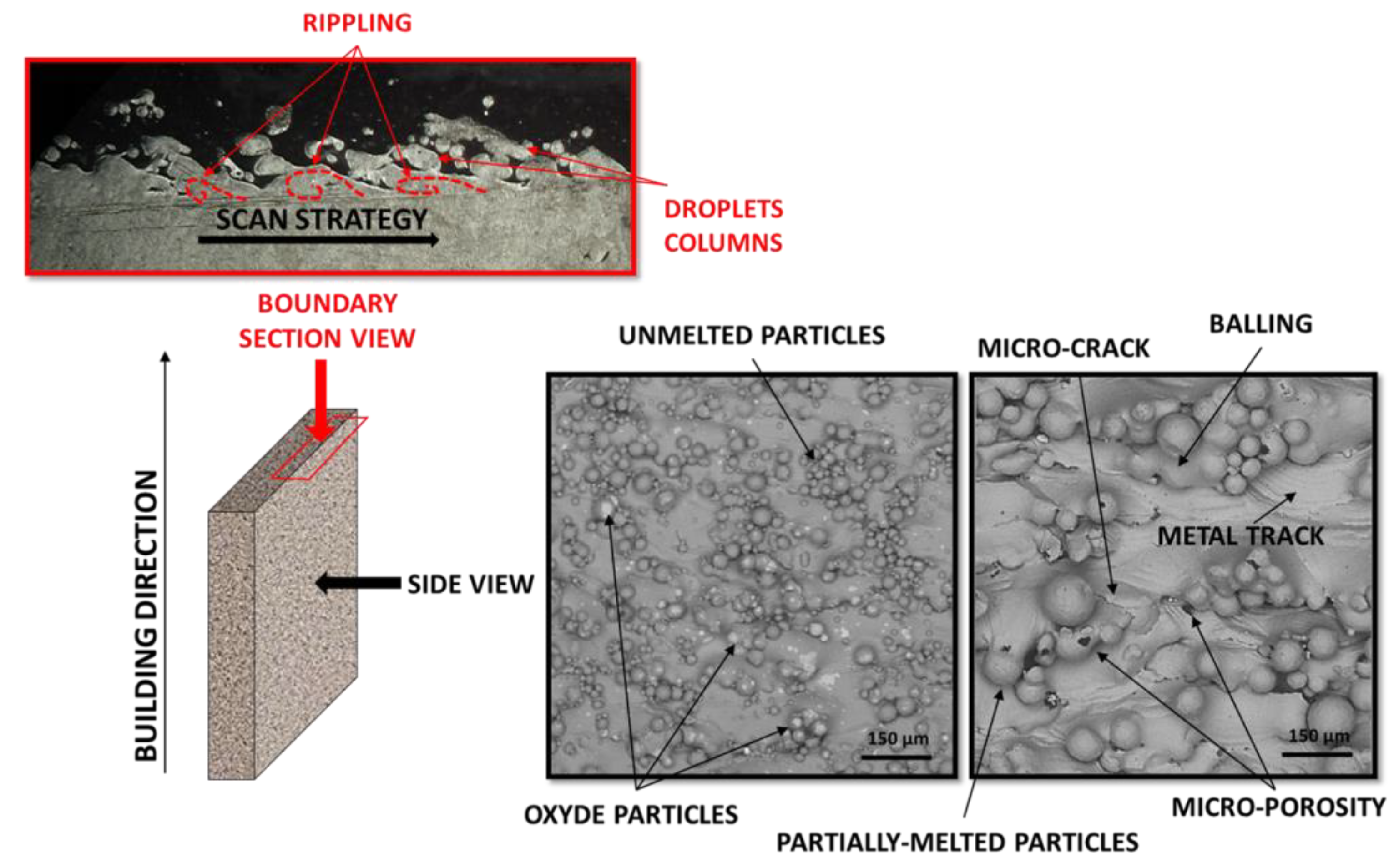
Figure 1. Representation of some possible surface defects of additively manufactured objects. Adapted from [6], with permission from Elsevier, 2020.
Metals 13 00874 g001
Figure 2. Schematisation of a general electrochemical setup to carry out the EP treatment. Adapted from [25], with permission from AIM, 2021.
Metals 13 00874 g002
Figure 3. Typical potential–current density curve obtained to establish the limiting current plateau (CD), where the efficiency of the EP treatment is maximum. Adapted from [25], with permission from AIM, 2021.
Metals 13 00874 g003
Figure 4. Mechanism proposed to explain the electropolishing phenomenon: (a) Viscous Theory by Jacquet; (b) Passive Theory by Hoar; (c) Salt-film Theory by Grimm and (d) Adsorbate-acceptor Theory by Matlosz.
Metals 13 00874 g004
Figure 5. Optical image of a profile surface of an additively manufactured part characterised by high roughness and dangerous re-entrant features. Adapted from [6].
Metals 13 00874 g005
Figure 6. Schematisation of DES type III, composed of a quaternary ammonium salt (ex. choline chloride, ChCl) and a hydrogen bond donor (ex. ethylene glycol) with a 2:1 molar ratio. Adapted from [55], with permission from Royal Society Of Chemistry, 2018.
Metals 13 00874 g006
Figure 7. Surface roughness of LPBF Ti6Al4V parts electropolished in an alcohol-based electrolytic solution added with 0.4 mol/L of sodium chloride. Reproduced from [76], with permission from Springer, 2020.
Metals 13 00874 g007
Figure 8. Potentiodynamic polarisation curves obtained in a Ringer solution at room temperature of Ti6Al4V additive manufactured parts electropolished in an alcohol-based solution. Reproduced from [76], with permission from Springer, 2020.
Metals 13 00874 g008
Figure 9. Schematisation of simple and complex LPBF Ti6Al4V parts. Reproduced from [80],with permission from Springer, 2021.
Metals 13 00874 g009
Figure 10. Surface roughness and thickness loss results of simple and complex LPBF Ti-6Al-4V parts electropolished in a green solution composed of ethanol, isopropyl alcohol, anhydrous aluminium, and anhydrous zinc chloride. Reproduced from [80], with permission from Springer, 2021.
Metals 13 00874 g010
Figure 11. Potential–current density curve of Ti6Al4V plate parts produced by EBM technique using an eco-friendly, ethylene-glycol-based solution. Adapted from [25], with permission from AIM, 2021.
Metals 13 00874 g011
Figure 12. Optical images (a) before and (b) after the EP treatment performed in an eco-friendly, ethylene-glycol-based solution at 25 V for 60 min. Adapted from [25], with permission from AIM, 2021.
Metals 13 00874 g012
Figure 13. Potential–current density curves recorded in different DESs for 316 L additive manufactured parts and for the cast counterpart to individuate the electropolishing range. The number 1 indicates the etching range; the number 2 indicates the passivating range; the number 3 and 4 indicate the beginning and finishing of the electropolishing range; the number 5 indicates the gas evolution zone. Reproduced from [81], with permission from IOP Science, 2019.
Metals 13 00874 g013
Figure 14. (a,b) Potentiodynamic polarisation curves obtained in a 3% NaCl solution of 316 L additive manufactured parts and the cast counterpart electropolished using different DESs. Reproduced from [81], with permission from IOP Science, 2019.
Metals 13 00874 g014
Figure 15. (a) Chrono-amperometric curves obtained performing the EP treatment at 6 V at 40 °C for a duration time between 30 and 60 min. (b) SEM picture of the electropolished sample applying a voltage of 6 V at a temperature of 40 °C for a duration of 45 min. Reproduced from [83], with permission from Springer, 2016.
Metals 13 00874 g015
Figure 16. Schematisation of anode electrodes with the differently oriented surface used. Adapted from [85].
Metals 13 00874 g016
Figure 17. Potential–current density curves recorded in the DES solution composed of choline chloride and ethylene glycol for LPBF IN625 additively manufactured parts at different values of voltage (4 V or 5 V) and temperature (40 °C or 50 °C) to individuate the optimal electropolishing range. Adapted from [85].
Metals 13 00874 g017
Figure 18. Variation of roughness at different duration time of EP treatment applying different conditions: (a) 5 V at 40 °C and (b) 4 V at 50 °C. Adapted from [85].
Metals 13 00874 g018
Figure 19. (a) Flat plate shape and (b) angled cylindrical porous tube of LPBF Hastelloy (HX) parts. Adapted from [86], with permission from Elsevier, 2022.
Metals 13 00874 g019
Figure 20. First row: As built; Second row: EP 5 min. (a) Optical and (b) SEM images of the top, (c) SEM images of the cornering and (d) SEM images of the bottom zones of the angled cylindrical porous tube after EP treatment in a DES solution, with an ethylene glycol and choline chloride base, at 70 °C and stirred at 400 rpm. DS stands for down-skin; SW stands for side-wall; US stands for upper-skin. Adapted from [86], with permission from Elsevier, 2022.
Metals 13 00874 g020
Table 1. Classification of Deep Eutectic Solvents.
TypeCompound ICompound II
Iquaternary ammonium saltmetal chloride
IIquaternary ammonium saltmetal chloride hydrate
IIIquaternary ammonium salthydrogen bonding donor (HBD)
IVmetal chloride hydratehydrogen bonding donor (HBD)
Table 2. Full factorial experimental design adopted from [79] to optimise the EP treatment.
ParametersLevels
Temperature (°C)26.737.8-
Voltage (V)6080-
Polishing time51020
Table 3. Full factorial experimental design adopted from [83] to optimise the EP treatment.
ParametersLevels
Voltage (V)468
Polishing time304560
Temperature (°C)204060
Table 4. A 52 full factorial experimental design adopted from [84] to optimise the EP treatment.
ParametersLevels
Temperature (°C)26.737.8
Electrode spacing (mm)715
Flow rate (mL/min)8001200
Voltage (V)6080
Flow-splitter configurationyesno
Table 5. EP parameters of the “green” treatment investigated to get the desired roughness.
MetalsPre-Polishing TreatmentSolutionTemperatureDuration TreatmentSolution SpeedPotential/
Cuurent Density
As-Built Roughness Initial RoughnessPost-EP Roughness
Ti6Al4V LPBFnoethylene glycol +magnesium chloride 0.5% water25 °C5–15 min500 rpm0.5 A/cm29.2 µm-1.3 µm
Ti6Al4V EPBFnoethyl alcohol+isopropyl alcohol+Zinc chloride+Aluminium chlorideroom temperature5–20 min-60–80 V30–40 µm -5–15 µm
Ti6Al4V LPBFnoethyl alcohol+ isopropyl alcohol+Zinc chloride+Aluminium chlorideroom temperature60–700 s500 rpm70V12 µm-3.5 µm
Ti6Al4V
EPBF
noethylene glycol-based -60 min-25V53 µm-10 µm
316L
LPBF
316L
cast
Mechanical GroundingCholine cloride+urea (1:2)
Choline cloride+ethylene glycol (1:2)
Choline cloride+malonic acid (1:1)
70 °C20 min500 rpm3.1 V vs SCE -200 nm1.7 ± 0.8 nm (cast)
2.0 ± 0.7 nm (ALM)
316L
LPBF
Laser RemeltingCholine cloride+ethylene glycol (1:2)+5% oxalic acid20 °C
40 °C
60 °C
30 min
45 min
60 min
300 rpm4 V
6 V
8 V
12 µm1.4 µm0.3–0.8 µm
Inconel 718 LPBFnoEthyl alcohol + opryl alcohol+ Zinc chloride Aluminium chloride 26.7 °C
7.8 °C
-800 or 1200 mL/m60 V
80 V
7.9 ± 0.3 µm-3 µm
Inconel 625 LPBFnoCholine cloride+ethylene glycol (1:2)25 °C
30 °C
40 °C
50 °C
4 h160 rpm4 V
5 V
17 µm (135°)
6 µm (90°) 9 µm (45°) 1.4 µm (0° )
-50 °C–4V 6 µm (135°) 2 µm (90°) 2 µm (45°) 1 µm (0°) 40 °C–5V 10 µm (135°) 3 µm (90°) 5 µm (45 °) 2 µm (0°)
Hastelloy LPBF (FLATE PLATE AND CYLINDRICAL TUBE)noCholine cloride+ethylene glycol (1:2)70 °C1–5 min400 rpm 19.5 mA/cm210.3 ± 0.7 μm (FLATE PLATE) 8–22 μm (CYLINDRICAL TUBE) -1.2 ± 0.1 μm
(FLAT PLATE) 1.7–4.5 μm (CYLINDRICAL TUBE)
Disclaimer/Publisher’s Note: The statements, opinions and data contained in all publications are solely those of the individual author(s) and contributor(s) and not of MDPI and/or the editor(s). MDPI and/or the editor(s) disclaim responsibility for any injury to people or property resulting from any ideas, methods, instructions or products referred to in the content.