Article

Difference Discretization Method for Milling Stability Prediction

School of Mechanical Engineering, Xi’an Jiaotong University, Xi’an 710049, China
Metals 2023, 13(5), 896; https://doi.org/10.3390/met13050896
Submission received: 22 March 2023 / Revised: 26 April 2023 / Accepted: 4 May 2023 / Published: 5 May 2023

Abstract

:
This paper proposes a difference discretization method (DDM) under a difference frame for the prediction of milling stability. In this method, the dynamic milling process is described by a delay differential equation (DDE) with two degrees of freedom rather than the traditional state-space form with a single discrete time delay. After discretization, only the velocity and acceleration in the DDE are approximated by the first- and second-order central difference for each smaller time interval, while the other items are kept unchanged. Then, the criterion for the optimal discretization interval number is put forward and derived based on the largest effective time interval (also called the critical time interval). The use of the critical time interval cannot only obtain sufficient accuracy, but also promotes as much efficiency as possible. Subsequently, a new DDM (NDDM) with varied discretization interval numbers as the milling rotating speeds is developed. Finally, the effectiveness of the proposed algorithm is demonstrated by using a benchmark example for a two-degrees-of- freedom milling model compared to the full discretization method (FDM) and the Hermite-interpolation full discretization method (HFDM). The results show that the proposed method has satisfactory stability charts and is able to increase the efficiency by 100% or more.

1. Introduction

Milling is a fundamental process in manufacturing industries that involves removing material from a workpiece using a rotating cutting tool. One of the main challenges in the milling process is the occurrence of chatter, which is an unstable vibration phenomenon that can lead to a range of problems. One of the most significant issues is that chatter can increase the wear rate of the cutting tool. When the tool vibrates excessively, it can cause wear and tear on the tool’s edge, which can result in a shortened tool life and increased manufacturing costs [1]. Another problem caused by chatter is reduced productivity. When chatter occurs, it can result in a reduced material removal rate. This is because the machine must be operated at a lower feed rate to avoid further vibrations, which can slow down the overall process. This can lead to decreased productivity, which can be a significant concern in a manufacturing setting [2]. In addition to reducing productivity, chatter can also result in poor surface quality of the machined parts. This is because the vibration of the cutting tool can result in irregularities on the surface of the workpiece. This can be especially problematic when machining high-precision components, where even small variations in surface quality are unacceptable. Finally, chatter can lead to decreased machining accuracy. This is because the vibration of the tool can result in deviations from the desired path of the cutting tool. This can cause inaccuracies in the machined part, which can result in costly rework or even scrapping the part.
To avoid chatter, the milling parameters, such as spindle speed and axial and radial milling depth, should be selected carefully [3,4]. The selection of these parameters should be based on the characteristics of the workpiece, the cutting tool, and the machine tool being used. A stability lobe diagram (SLD) is an important tool for chatter suppression and can be used as a guide for parameter selection [5]. It is a graphical representation of the stability limits of a milling process, which can be used to determine the optimal cutting conditions for a given combination of machine tool, workpiece, and cutting tool. By using a SLD, the milling parameters can be adjusted to avoid chatter, which can lead to improved tool life, increased productivity, better surface quality, and higher machining accuracy.
In recent decades, there has been much research focused on developing methods to obtain the SLD more quickly and accurately. These methods can be broadly categorized into three categories: experimental methods [6], numerical methods [7], and semi-analytical methods. Experimental methods are the most accurate, but are not practical due to the high cost involved. These methods involve conducting experiments to measure the stability of the milling system under different cutting conditions. The results of these experiments can then be used to construct the SLD. While these methods can provide the most accurate SLD, they are not suitable for routine use due to their high cost and time-consuming nature. Numerical methods, on the other hand, are more feasible in terms of their cost and time requirements, but are not as accurate as the experimental methods. These methods involve simulating the milling process using numerical techniques. The simulation results can then be used to construct the SLD. While these methods are more feasible than experimental methods, they require extensive computations and are usually used to verify whether the semi-analytical methods are correct or not. Semi-analytical methods are a popular approach for predicting the stability of the milling process. These methods can be further divided into two categories: frequency-domain [5,8] and time-domain methods [9,10,11,12,13]. In frequency-domain methods, semi-analytical methods use zero-order approximation and multi-frequency methods to consider the first item and the first few items of the Fourier series of the dynamic milling coefficients, respectively. These methods are useful when the system is linear and time-invariant. However, in practice, milling systems are often nonlinear and time-varying, which limits the applicability of frequency-domain methods. In contrast, time-domain semi-analytical methods are more versatile and can handle multiple delays, runout, variable helix and pitch, nonlinearity, and other factors that affect the stability of the milling process. These methods can be used to predict the stability of the milling process under a wide range of cutting conditions. Time-domain semi-analytical methods usually refer to discretization methods. Discretization methods involve dividing the time domain into smaller intervals and approximating the milling system’s behavior within each interval. Until now, discretization methods have mainly been divided into two kinds: the semi-discretization method (SDM) [14] and the full-discretization method (FDM) [15]. While there are other discretization methods available, many of them are simply improvements or variations of the SDM and FDM. However, both the SDM and FDM have limitations when it comes to solving delay differential equations (DDEs). The solution of DDEs under these two frames requires the calculation of the matrix exponential function, which can be computationally expensive and inefficient. To address these limitations, researchers have developed more efficient methods, such as the tau method and the spectral tau method. These methods use semi-analytical or analytical solutions and have been shown to be highly accurate and efficient at solving DDEs. For production, and especially for SLD optimization, which requires performing semi-analytical methods multiple times, faster methods are still necessary. Therefore, the search for even more efficient methods to solve DDEs continues.
This paper proposes a novel approach for predicting milling stability using a difference discretization method under a difference frame. Unlike existing methods that involve complex and time-consuming matrix exponential functions, this approach uses simple addition and multiplication operations to calculate differences in velocity and acceleration. As a result, it has a high computational efficiency, making it practical for industrial applications. The paper also puts forward a criterion for determining the optimal discretization interval number based on the critical time interval. This criterion enables the development of NDDM with varied discretization interval numbers that are suitable for both low-speed and high-speed domains. The proposed method is further applied to problems such as the helix angle, surface location error, and multiple time delays, which demonstrate its ability to handle these issues effectively.
The remainder of the paper is organized as follows. Section 2 presents a mathematical model of the dynamic milling process, which serves as the basis for the proposed approach. Section 3 describes the derivation of the difference discretization method (DDM) used in the approach. In Section 4, the equation for calculating the optimal discretization interval number is presented, along with the NDDM with varied discretization interval numbers. Section 5 provides a benchmark example for a two-degree-of-freedom milling model to illustrate the efficiency of the proposed approach. A convergence analysis is also given to demonstrate the accuracy of the solution. Finally, Section 6 presents the conclusions of this study, highlighting the significance of the proposed approach for predicting milling stability. The proposed approach offers a practical solution for predicting milling stability, with a high computational efficiency and the ability to handle complex problems. Its effectiveness has been demonstrated through the benchmark example and its application to various problems. Future research could explore the application of the proposed approach to other machining processes and the integration of additional factors, such as tool wear and material properties.

2. Mathematical Model

Assuming that the workpiece and the milling tool are rigid and flexible, respectively, a simplified mass-damping-spring model with two degrees of freedom (DOF) can be used to describe the dynamic milling process, as shown in Figure 1. In consideration of the regenerative effect, the mathematical model can be expressed as a second-order delay differential equation (DDE) as follows [9]:
M Q ¨ ( t ) + C Q ˙ ( t ) + K Q ( t ) = a p H ( t ) [ Q ( t ) Q ( t τ ) ]
where Q ( t ) = x ( t ) , y ( t ) T is the displacement vector in the x and y directions; M , C , K are the modal mass matrix, modal damping matrix, and modal stiffness matrix, respectively; a p is the axial milling depth; τ = 60 / N / n is the time delay due to the regenerative effect, where N is the tool teeth number and n represents the spindle speed in rpm. H ( t ) is the dynamic milling force coefficient matrix and satisfies H ( t ) = H ( t + τ ) . H ( t ) can be expressed as
H ( t ) = j = 1 N g ( ϕ j ( t ) ) K t s c + K n s 2 K t c 2 + K n s c K t s 2 + K n s c K t s c + K n c 2
where s = sin ( ϕ j ( t ) ) and c = cos ( ϕ j ( t ) ) . K t and K n are the tangential and normal linearized cutting force coefficients, respectively. g ( ϕ j ( t ) ) is the switching function determining whether the jth tooth is in cut or not [9]. ϕ j ( t ) is the angular position of the jth tooth and is given by
ϕ j ( t ) = 2 π n t / 60 + ( j 1 ) 2 π / N

3. Difference Discretization Method

In order to solve Equation (1), the first step is to discretize the time period τ = m Δ t , where m is an integer. For the small time interval t i 1 , t i + 1 , i = 2 , 3 , , m , Equation (1) can be given by
M Q ¨ i + C Q ˙ i + K Q i = a p H i ( Q i Q i m )
Using the central difference formulas Q ˙ i = ( Q i + 1 Q i 1 ) / 2 / Δ t and Q ¨ i = ( Q i + 1 2 Q i + Q i 1 ) / Δ t 2 , Equation (4) can be approximated as
M ( Q i + 1 2 Q i + Q i 1 ) / Δ t 2 + C ( Q i + 1 Q i 1 ) / 2 / Δ t + K Q i = a p H i ( Q i Q i m )
Then, Equation (5) can be rearranged into
M Δ t 2 + C 2 Δ t Q i + 1 + 2 M Δ t 2 + K + a p H i Q i + M Δ t 2 C 2 Δ t Q i 1 = a p H i Q i m
which can be simplified as
Q i + 1 = A 1 Q i + A 2 Q i 1 + A 3 Q i m
where
A 1 = M Δ t 2 + C 2 Δ t 1 2 M Δ t 2 + K + a p H i
A 2 = M Δ t 2 + C 2 Δ t 1 M Δ t 2 C 2 Δ t
A 3 = M Δ t 2 + C 2 Δ t 1 a p H i
Therefore, an m + 1 -dimensional discrete map can be defined as
Z i + 1 = D i Z i , i = 1 , 2 , 3 , , m
where Z i = [ Q i , Q i 1 , Q i 2 , , Q i m ] ( m + 1 ) × 1 T and
D i = A 1 A 2 0 0 A 3 I 0 0 0 0 0 I 0 0 0 0 0 0 0 0 0 0 0 I 0 ( m + 1 ) × ( m + 1 )
The approximate transition matrix is obtained as
Φ = D m D m 1 D m 2 D 1
On the basis of the Floquet theory, if the maximal eigenvalue in a magnitude of Φ is less than one, the system is stable; otherwise, it is unstable.

4. The NDDM with Varied Discretization Interval Numbers

Although the DDM has a simple form and high efficiency, the accuracy of its central difference scheme is limited by the time step. This section will derive the calculation formula for the optimal discretization interval number based on the critical time step.

4.1. The Criterion for Optimal Discretization Interval Number Calculation

With the discretization interval number m , spindle rotating speed n in rpm, and the milling tool tooth number N , the time step can be given by
Δ t = 60 m n N
It can easily be shown that the time step will decrease as n increases. The smaller the time step is, the better accuracy this method has. The DDM has the lowest suitable spindle rotating speed, n 0 . In order to obtain a SLD with enough accuracy for the range of spindle speed, there exists the critical time step, Δ t 0 , which stays the same for different milling conditions and is just related to the adopted algorithm. Thus, for a specific n 0 , m , and N , the critical time step, Δ t 0 , can be calculated as the following:
Δ t 0 = 60 m n 0 N
According to Equation (15), with the critical time step, Δ t 0 , and the required spindle rotating speed, n , the criterion for the optimal discretization-interval-number calculation can be written as
m = 60 Δ t 0 n N
where the steps of Δ t 0 can be determined as seen in Figure 2: (1) With a random m and N , the reference SLD can be obtained using the DDM. (2) Comparing the reference SLD with the standard SLD for a SDM with m = 200 , the lowest suitable spindle rotating speed, n 0 , can be found. (3) According to Equation (15), Δ t 0 can be calculated. (4) The last, but not least, step is to adopt different parameters to test whether the critical time steps under the different parameters are the same or not.

4.2. The Description of the NDDM

The other discretization methods (such as SDM, FDM, HFDM, etc.) do not have the critical time step, Δ t 0 , because the calculation of the matrix exponential function is not linear and the accuracy has nothing to do with spindle speed. Due to the linear properties of the central difference method, the proposed method has the useful critical time step. Inspired by this concept, we can force all the time steps under the different spindle speeds, n , to be the critical time step, Δ t 0 , which will cause varied discretization interval numbers, m , for the different spindle speeds. The NDDM not only achieves sufficient accuracy, but also promotes as much efficiency as possible, which is suitable for both low-speed and high-speed domains.

4.3. The Calculation of the Critical Time Step

According to the flowchart in Figure 2, this section will calculate the critical time step, Δ t 0 . A detailed description of the calculation is as follows:
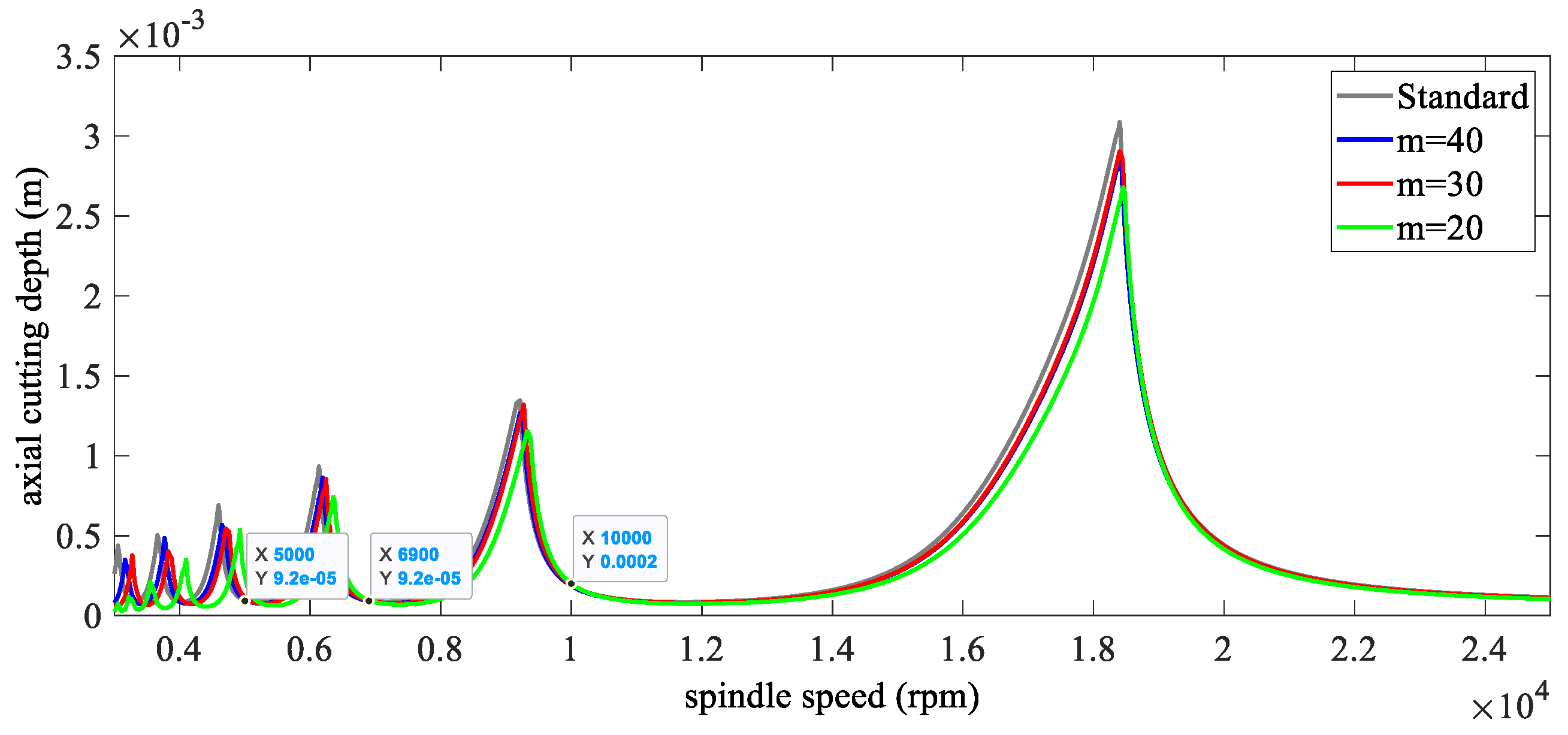
Firstly, the milling parameters are given as: a four-fluted cutter, down milling, the radial immersion ratio is 0.5, the natural frequency is 922 Hz, the relative damping is 0.011, the modal mass is 0.03993 kg, and the cutting force coefficients are 6 × 10 8 N / m 2 and 2 × 10 8 N / m 2 . With m = 200 , the standard SLD can be obtained as the gray line in Figure 3.
Secondly, with m = 40 , 30 , 20 , the reference SLDs using DDM are shown as the blue, red, and green lines in Figure 3.
Thirdly, comparing these SLDs, the lowest suitable spindle speed can be determined as n 0 = 4000 , 5000 , 8000 rpm .
Fourthly, according to Equation (15), the critical time steps can be calculated as Δ t = 9.375 × 10 5 , 10 × 10 5 , 9.375 × 10 5 . The three calculated values are quite close. Therefore, the smallest value can be selected as the critical time step, Δ t 0 = 9.375 × 10 5 .
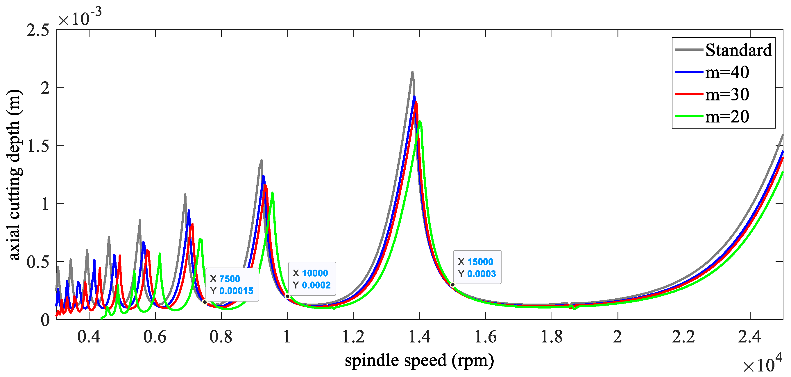
Finally, the different tooth numbers ( N = 2 , 3 ) are adopted to validate the above calculated critical time step, Δ t 0 . The SLDs are shown in Figure 4 and Figure 5. According to Equation (15), the critical time steps can be obtained as Δ t = 10 × 10 5 , 9.662 × 10 5 , 10 × 10 5 ,   10 × 10 5 , 10 × 10 5 . The calculated values are almost equal to Δ t 0 = 9.375 × 10 5 . Therefore, the smallest value 9.375 × 10 5 can be selected as the critical time step.

5. Verification

In order to validate the effectiveness of the proposed method, this section adopts the benchmark example for the two-degrees-of-freedom milling model compared to the FDM and HFDM. The milling parameters are the same as in Section 4.3. The computer programs are written in MATLAB R2014a and implemented on a desktop computer (Intel(R) Core(TM) i7-4793 CPU, 3.60GHz, 16.0 GB).

5.1. Stability Lobe Diagrams

In this section, the SLDs and the elapsed CPU time are obtained for 3000 rpm–25,000 rpm for FDM, HFDM, DDM, and NDDM over a 400 × 200 -sized grid of parameters. For reference, the SLD from the SDM with m = 200 is calculated and presented in grey in each figure as the exact benchmark. From Figure 6, it is seen that the proposed method has satisfactory stability charts and is able to increase the efficiency by 100% or more. For larger discretization interval numbers, NDDM has a much greater advantage.

5.2. Rate of Convergence Analysis

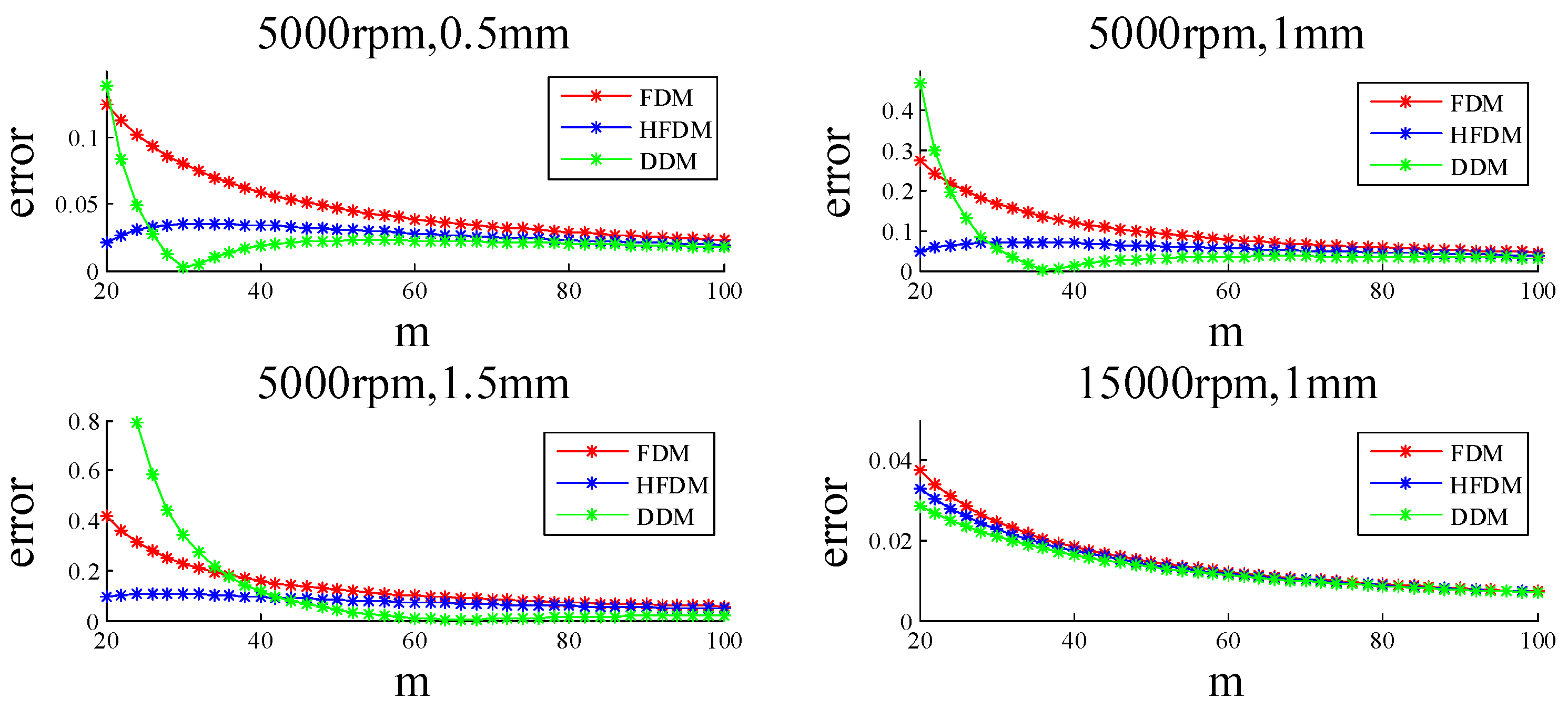
With the same parameters, the convergence of the critical eigenvalues with respect to the different approximation parameters, m , can be obtained as shown in Figure 7. It shows that these methods have the same approximate accuracy with large approximation parameters, m , and the DDM has a faster convergence rate without a loss of numerical precision.

6. Application

In order to further verify the effectiveness of the proposed DDM, different milling conditions are adopted, for example, helix angle and surface location error (SLE), multiple time delays, and periodic delay problems.

6.1. Helix Angle and Surface Location Error

As shown in [4], the cutting part of a milling tool is divided into N a slices along the axial direction; therefore, the thickness of each slice is Δ a p = a p / N a and the height of the ith slice is z = i × Δ a p . Considering the helix and feed effects, the governing equation can be given by [13]
M X ¨ ( t ) + C X ˙ ( t ) + K X ( t ) = K c ( t ) [ X ( t ) X ( t τ ) ] + f 0 ( t )
where
K c ( t ) = i = 1 N a j = 1 N g ( ϕ j ( z , t ) ) Δ a p K t s c K n s 2 K t c 2 K n s c K t s 2 K n s c K t s c K n c 2
f 0 ( t ) = i = 1 N a j = 1 N g ( ϕ j ( z , t ) ) Δ a p f t K t s c K n s 2 K t c 2 K n s c K t s 2 K n s c K t s c K n c 2
where c = cos ( ϕ j ( z , t ) ) and s = sin ( ϕ j ( z , t ) ) . ϕ j ( z , t ) is the angular position of the jth tooth at a height of z .
Discretizing the time period τ = m Δ t , where m is an integer, Equation (17) can be given by
M X ¨ i + C X ˙ i + K X i = K c i ( X i X i m ) + f 0 i
Substituting the central difference formulas X ˙ i = ( X i + 1 X i 1 ) / 2 / Δ t and X ¨ i = ( X i + 1 2 X ˙ i + X i 1 ) / Δ t 2 into Equation (17) leads to
M ( X i + 1 2 X ˙ i + X i 1 ) / Δ t 2 + C ( X i + 1 X i 1 ) / 2 / Δ t + K X i = K c i ( X i X i m ) + f 0 i
Then, Equation (21) can be rearranged into
M Δ t 2 + C 2 Δ t X i + 1 + 2 M Δ t 2 + K + K c i X i + M Δ t 2 C 2 Δ t X i 1 = K c i X i m + f 0 i
which can be simplified as
X i + 1 = A 1 X i + A 2 X i 1 + A 3 X i m + A 4
where
A 1 = M Δ t 2 + C 2 Δ t 1 2 M Δ t 2 + K + K c i
A 2 = M Δ t 2 + C 2 Δ t 1 M Δ t 2 C 2 Δ t
A 3 = M Δ t 2 + C 2 Δ t 1 K c i
A 4 = M Δ t 2 + C 2 Δ t 1 f 0 i
Therefore, the m + 1 -dimensional discrete map can be obtained as
Z i + 1 = D i Z i + E i , i = 1 , 2 , 3 , , m
where Z i = [ X i , X i 1 , X i 2 , , X i m ] ( m + 1 ) × 1 T , E i = [ A 4 , 0 , 0 , , 0 ] ( m + 1 ) × 1 T , and
D i = A 1 A 2 0 0 A 3 I 0 0 0 0 0 I 0 0 0 0 0 0 0 0 0 0 0 I 0
Then, the transition relation between Z m + 1 and Z 1 can be expressed as
Z m + 1 = D m D m 1 D m 2 D 1 Z 1 + i = 1 m A 4 D m D m 1 D m i + 1 = Φ Z 1 + R
According to the Floquet theory, the stability of the system can be determined by judging whether the maximal eigenvalue of the transition matrix, Φ , is less than one or not. If not, the system is unstable; otherwise, it is stable.
As similarly used in the TFEA method [14], fixed points of the map, which identify the stable periodic motions of the system, occur when Z m + 1 = Z 1 . The fixed points of the discrete map, denoted by Z * , represent the stable periodic motions of the system [15] and can be obtained from
Z * = ( I Φ ) 1 R
Finally, the SLE can be calculated by using the steady-state coefficient vector.
With the same parameters as [15], the SLD with a helix angle of 30° can be seen in Figure 8 and the SLE can be seen in Figure 9. These two figures are the same as the results from [15], which validate the effectiveness of the proposed method.

6.2. Multiple Time Delays

In general, the multiple time-delays problem in milling is mainly caused by the variable pitch cutter effect and the cutter runout effect [16]. Here, we take the variable pitch as the example for validation of the proposed method for the multiple time-delays problem.
For variable pitch, the dynamic Equation (1) can be rewritten as
M X ¨ ( t ) + C X ˙ ( t ) + K X ( t ) = a p j = 1 N H j ( t ) [ X ( t ) X ( t τ j ) ]
where T = 60 / Ω is the principle period and τ j is the time delay of the jth tooth, which satisfies T = j = 1 N τ j . The angular position of the jth tooth can be given by
ϕ j ( t ) = 2 π Ω t / 60 , j = 1 2 π Ω t / 60 + n = 1 j 1 φ n , j > 1
where φ i is the pitch angle between tooth i and tooth i + 1 . H j ( t ) can be expressed as
H j ( 1 , 1 ) = g ( ϕ j ( t ) ) sin ( ϕ j ( t ) ) K t cos ( ϕ j ( t ) ) + K n sin ( ϕ j ( t ) )
H j ( 1 , 2 ) = g ( ϕ j ( t ) ) cos ( ϕ j ( t ) ) K t cos ( ϕ j ( t ) ) + K n sin ( ϕ j ( t ) )
H j ( 2 , 1 ) = g ( ϕ j ( t ) ) sin ( ϕ j ( t ) ) K t sin ( ϕ j ( t ) ) + K n cos ( ϕ j ( t ) )
H j ( 2 , 2 ) = g ( ϕ j ( t ) ) cos ( ϕ j ( t ) ) K t sin ( ϕ j ( t ) ) + K n cos ( ϕ j ( t ) )
Discretizing Equation (32) with the principle period T = m Δ t , where m is an integer and T is the spindle rotating period, leads to
M X ¨ i + C X ˙ i + K X i = a p j = 1 N H j i X i + a p j = 1 N H j i X i m j
Using the central difference formulas X ˙ i = ( X i + 1 X i 1 ) / 2 / Δ t and X ¨ i = ( X i + 1 2 X ˙ i + X i 1 ) / Δ t 2 , Equation (38) can be approximated as
M ( X i + 1 2 X ˙ i + X i 1 ) / Δ t 2 + C ( X i + 1 X i 1 ) / 2 / Δ t + K X i + a p j = 1 N H j i X i = a p j = 1 N H j i X i m j
where m 1 = int ( φ 1 / Ω / Δ t ) , m 2 = int ( ( φ 1 + φ 2 ) / Ω / Δ t ) m 1 , , m N = int ( T / Δ t ) j = 1 N 1 m j , and m = j = 1 N m j . The symbol ‘int’ means rounding.
Then, Equation (39) can be rearranged into
M Δ t 2 + C 2 Δ t X i + 1 + 2 M Δ t 2 + K + a p j = 1 N H j i X i + M Δ t 2 C 2 Δ t X i 1 = a p j = 1 N H j i X i m j
which can be simplified as
X i + 1 = A 1 X i + A 2 X i 1 + j = 1 N A 3 j X i m j
where
A 1 = M Δ t 2 + C 2 Δ t 1 2 M Δ t 2 + K + a p j = 1 N H j i
A 2 = M Δ t 2 + C 2 Δ t 1 M Δ t 2 C 2 Δ t
A 3 j = a p M Δ t 2 + C 2 Δ t 1 H j i
Therefore, a m + 1 -dimensional discrete map can be defined as
Z i + 1 = D i Z i , i = 1 , 2 , 3 , , m
where Z i = [ X i , X i 1 , X i 2 , , X i m ] ( m + 1 ) × 1 T and
D i = A 1 A 2 0 0 0 I 0 0 0 0 0 I 0 0 0 0 0 I 0 0 0 0 0 I 0 + j = 1 N 0 0 A 3 j 0 0 0 0 0 0 0 0 0 0 0 0 0 0 0 0 0
The horizontal position of the discrete input matrices, A 3 j , depends on the value of m j and begins from 2 m j + 1 to 2 m j + 2 .
According to the Floquet theory, the stability of the system can be determined by judging whether the maximal eigenvalue of the transition matrix, Φ , is less than one or not. If not, the system is unstable; otherwise, it is stable.
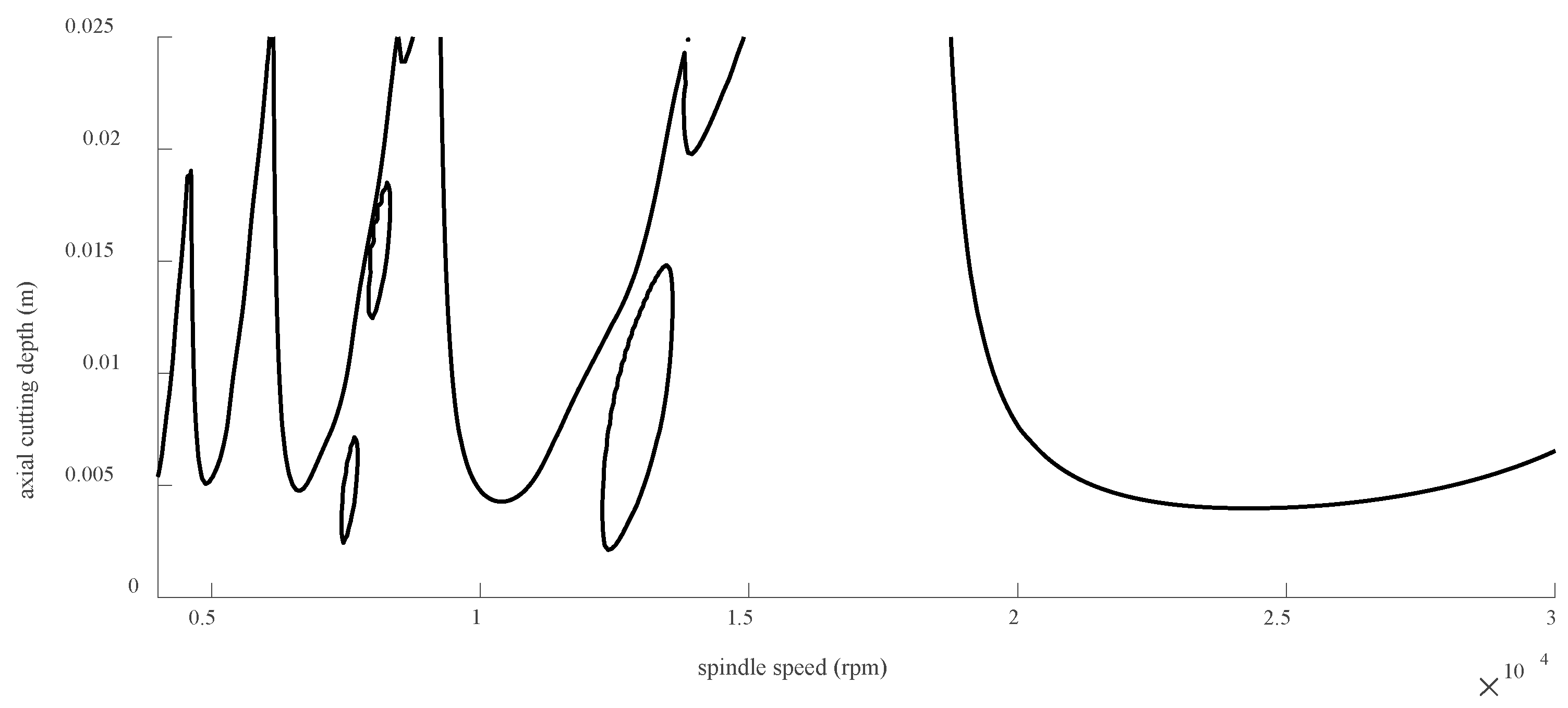
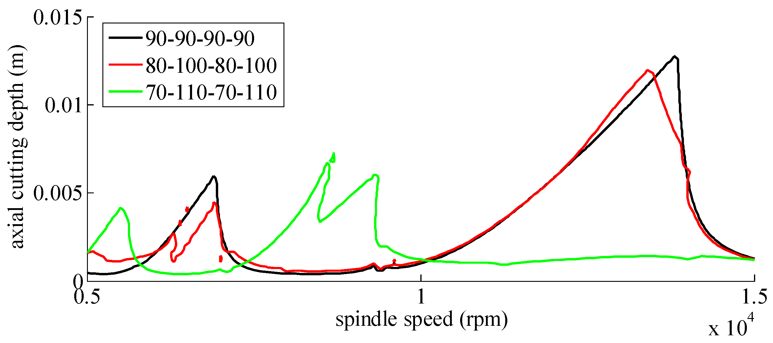
The structural dynamic and operational parameters of the adopted example are: a four-fluted cutter, up-milling, the cutting force coefficients are K t = 600 MPa and K t = 200 Mpa , the natural frequency is f n x = f n y = 922 Hz , the relative damping is ξ x = ξ y = 0.011 , the modal mass is m t x = m t y = 0.03993 , the radial immersion ratio is a D = 0.1 , and the pitch angles are 90 90 90 90 , 80 100 80 100 , and 70 110 70 110 . The SLDs can be seen in Figure 10.

6.3. Periodic Time Delay Variable Spindle Speed

A variable spindle speed will result in periodic time-delay problems in the dynamic milling process. Here, we take a sinusoidal modulation of the spindle speed as the example:
Ω ( t ) = Ω 0 + Ω 1 sin ( 2 π T 1 t ) = Ω 0 [ 1 + RVA sin ( RVF 2 π 60 Ω 0 t ) ]
where Ω 0 is the nominal spindle speed. Ω 1 and T 1 are the amplitude and period of the spindle speed variation, respectively. RVA = Ω 1 / Ω 0 and RVF = 60 / Ω 0 / T 1 represent the modulation amplitude ratio and frequency ratio, respectively. Therefore, the angular position of the jth tooth can be given by
ϕ j ( t ) = 2 π 60 0 t Ω ( s ) d s + ( j 1 ) 2 π N = 2 π 60 Ω 0 t + 60 RVA 2 π RVF ( 1 cos ( 2 π T 1 t ) ) + ( j 1 ) 2 π N
The periodic delay, τ ( t ) , can be obtained from the implicit form
t τ ( t ) t Ω ( s ) 60 d s = 1 / N
For small RVA and RVF, τ ( t ) can be approximated as
τ ( t ) = τ 0 [ 1 RVA sin ( RVF 2 π 60 Ω 0 t ) ]
where τ 0 = 60 / N / Ω 0 .
According to [17], Equation (1), under variable spindle speed, can be rewritten as
M X ¨ ( t ) + C X ˙ ( t ) + K X ( t ) = a p H ( t ) [ X ( t ) X ( t τ ( t ) ) ]
Thus, the principle period, T , can be expressed as
T = q T 1 = p τ 0
where q and p are relatively prime. T can be selected as the Floquet period.
Discretizing Equation (51) with the principle period, T = m Δ t , and m i = int ( τ i / Δ t ) , where m is an integer, leads to
M X ¨ i + C X ˙ i + K X i = a p H i ( X i X i m i )
Then, using the central difference formulas X ˙ i = ( X i + 1 X i 1 ) / 2 / Δ t and X ¨ i = ( X i + 1 2 X ˙ i + X i 1 ) / Δ t 2 , Equation (53) can be approximated as
M ( X i + 1 2 X ˙ i + X i 1 ) / Δ t 2 + C ( X i + 1 X i 1 ) / 2 / Δ t + K X i = a p H i ( X i X i m i )
Then, Equation (54) can be rearranged into
M Δ t 2 + C 2 Δ t X i + 1 + 2 M Δ t 2 + K + a p H i X i + M Δ t 2 C 2 Δ t X i 1 = a p H i X i m i
which can be simplified as
X i + 1 = A 1 X i + A 2 X i 1 + A 3 i X i m i
where
A 1 = M Δ t 2 + C 2 Δ t 1 2 M Δ t 2 + K + a p H i
A 2 = M Δ t 2 + C 2 Δ t 1 M Δ t 2 C 2 Δ t
A 3 i = M Δ t 2 + C 2 Δ t 1 a p H i
Therefore, a m + 1 -dimensional discrete map can be defined as
Z i + 1 = D i Z i , i = 1 , 2 , 3 , , m
where Z i = [ X i , X i 1 , X i 2 , , X i m ] ( m + 1 ) × 1 T and
D i = A 1 A 2 0 0 A 3 i 0 0 0 I 0 0 0 0 0 0 0 0 I 0 0 0 0 0 0 0 0 0 0 0 0 0 0 0 0 0 0 0 0 I 0 ( m + 1 ) × ( m + 1 )
The horizontal position of the discrete input matrices, A 3 i , depends on the value of m i and begins from 2 m i + 1 to 2 m i + 2 .
According to the Floquet theory, the stability of the system can be determined by judging whether the maximal eigenvalue of the transition matrix, Φ , is less than one or not. If not, the system is unstable; otherwise, it is stable.
The structural dynamic and operational parameters of the adopted example are: a four-fluted cutter, up-milling, the cutting force coefficients are K t = 600 MPa and K t = 200 Mpa , the natural frequency is f n x = f n y = 922 Hz , the relative damping is ξ x = ξ y = 0.011 , the modal mass is m t x = m t y = 0.03993 , the radial immersion ratio is a D = 0.1 , RVA = 0 . 1 , and RVF = 0 . 1 . The SLDs can be seen in Figure 11.

7. Conclusions

This paper presents a novel approach for predicting milling stability using a difference discretization method under a difference frame. The method involves approximating only the velocity and acceleration in the delay differential equation using the first- and second-order central difference for smaller time intervals, while keeping the other items unchanged. This approach enables the prediction of stability while maintaining the accuracy of the solution. Furthermore, the paper proposes a criterion for determining the optimal discretization interval number based on the critical time interval. This criterion enables the development of a NDDM that varies the discretization interval number according to the milling rotating speeds. As a result, the NDDM is suitable for both low-speed and high-speed domains. The effectiveness of the proposed algorithm is demonstrated using a benchmark example of a two-degree-of-freedom milling model compared to that of the FDM and HFDM. The results show that the proposed method has satisfactory stability charts and can increase efficiency by 100% or more. This suggests that the proposed method has practical value for industrial applications. The proposed approach is significant as it overcomes the limitations of existing methods that require a trade-off between accuracy and computational efficiency. Additionally, the NDDM is able to handle varying rotating speeds, which is an important aspect of milling stability predictions. This approach is also unique, in that it only approximates the velocity and acceleration of the DDE, while keeping other items unchanged, which ensures the accuracy of the solution. In conclusion, the proposed difference discretization method under a difference frame is a promising approach for predicting milling stability. The method is accurate, efficient, and suitable for varying rotating speeds, making it practical for industrial applications. Further research could explore the application of the proposed approach to other machining processes and the integration of additional factors, such as tool wear and material properties.

Funding

This work was supported in part by the National Science Foundation of China under grants 52105480 and 52175114 and the China Postdoctoral Science Foundation under grants 2022T150517 and 2021M692589.

Institutional Review Board Statement

Not applicable.

Informed Consent Statement

Written informed consent was obtained from all subjects involved in this study.

Data Availability Statement

Not applicable.

Conflicts of Interest

The author declares there is no conflict of interest.

References

  1. Quintana, G.; Ciurana, J. Chatter in machining processes: A review. Int. J. Mach. Tools Manuf. 2011, 51, 363–376. [Google Scholar] [CrossRef]
  2. Siddhpura, M.; Paurobally, R. A review of chatter vibration research in turning. Int. J. Mach. Tools Manuf. 2012, 61, 27–47. [Google Scholar] [CrossRef]
  3. Wang, C.; Zhang, X.; Liu, Y.; Cao, H.; Chen, X. Stiffness variation method for milling chatter suppression via piezoelectric stack actuators. Int. J. Mach. Tools Manuf. 2017, 124, 53–66. [Google Scholar] [CrossRef]
  4. Wang, C.; Zhang, X.; Cao, H.; Chen, X.; Xiang, J. Milling stability prediction and adaptive chatter suppression considering helix angle and bending. Int. J. Adv. Manuf. Technol. 2017, 95, 3665–3677. [Google Scholar] [CrossRef]
  5. Altintaş, Y.; Budak, E. Analytical Prediction of Stability Lobes in Milling. CIRP Ann. 1995, 44, 357–362. [Google Scholar] [CrossRef]
  6. Quintana, G.; Ciurana, J.; Ferrer, I.; Rodríguez, C.A. Sound mapping for identification of stability lobe diagrams in milling processes. Int. J. Mach. Tools Manuf. 2009, 49, 203–211. [Google Scholar] [CrossRef]
  7. Li, H.; Shin, Y. A Comprehensive Dynamic End Milling Simulation Model. J. Manuf. Sci. Eng. 2006, 128, 86–95. [Google Scholar] [CrossRef]
  8. Merdol, S.D.; Altintas, Y. Multi Frequency Solution of Chatter Stability for Low Immersion Milling. J. Manuf. Sci. Eng. 2004, 126, 459–466. [Google Scholar] [CrossRef]
  9. Ding, Y.; Zhu, L.; Zhang, X.; Ding, H. A full-discretization method for prediction of milling stability. Int. J. Mach. Tools Manuf. 2010, 50, 502–509. [Google Scholar] [CrossRef]
  10. Liu, Y.; Zhang, D.; Wu, B. An efficient full-discretization method for prediction of milling stability. Int. J. Mach. Tools Manuf. 2012, 63, 44–48. [Google Scholar] [CrossRef]
  11. Insperger, T.; Stépán, G. Updated semi-discretization method for periodic delay-differential equations with discrete delay. Int. J. Numer. Methods Eng. 2004, 61, 117–141. [Google Scholar] [CrossRef]
  12. Ozoegwu, C.; Omenyi, S.; Ofochebe, S. Hyper-third order full-discretization methods in milling stability prediction. Int. J. Mach. Tools Manuf. 2015, 92, 1–9. [Google Scholar] [CrossRef]
  13. Mann, B.P.; Edes, B.T.; Easley, S.J.; Young, K.A.; Ma, K. Chatter vibration and surface location error prediction for helical end mills. Int. J. Mach. Tools Manuf. 2008, 48, 350–361. [Google Scholar] [CrossRef]
  14. Mann, B.; Young, K.A.; Schmitz, T.L.; Dilley, D.N. Simultaneous Stability and Surface Location Error Predictions in Milling. J. Manuf. Sci. Eng. 2005, 127, 446–453. [Google Scholar] [CrossRef]
  15. Insperger, T. Full-discretization and semi-discretization for milling stability prediction: Some comments. Int. J. Mach. Tools Manuf. 2010, 50, 658–662. [Google Scholar] [CrossRef]
  16. Zhang, X.; Xiong, C.; Ding, Y.; Xiong, Y. Variable-step integration method for milling chatter stability prediction with multiple delays. Sci. China Technol. Sci. 2011, 54, 3137–3154. [Google Scholar] [CrossRef]
  17. Xie, Q.; Zhang, Q. Stability predictions of milling with variable spindle speed using an improved semi-discretization method. Math. Comput. Simul. 2012, 85, 78–89. [Google Scholar] [CrossRef]
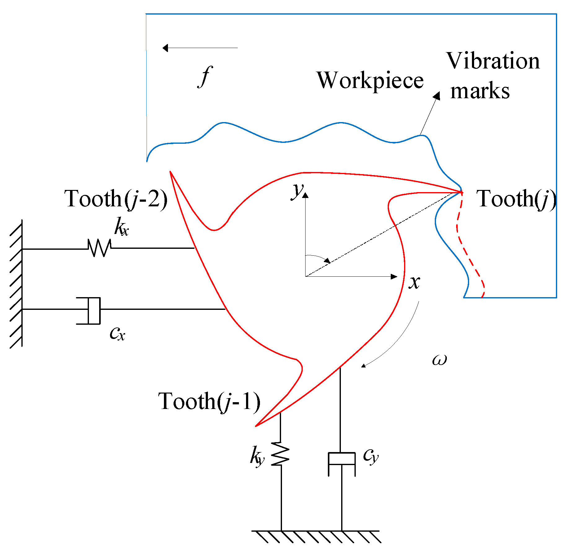
Figure 1. Schematic diagram of the dynamic milling process.
Metals 13 00896 g001
Figure 2. The flowchart for calculating the critical time step, Δ t 0 .
Metals 13 00896 g002
Figure 3. The standard SLD and reference SLDs with N = 4 .
Metals 13 00896 g003
Figure 4. The standard SLD and reference SLDs with N = 3 .
Metals 13 00896 g004
Figure 5. The standard SLD and reference SLDs with N = 2 .
Metals 13 00896 g005
Figure 6. Comparison of methods for the two-DOF milling model.
Metals 13 00896 g006
Figure 7. Convergence of the eigenvalues for different approximation parameters, m .
Metals 13 00896 g007
Figure 8. SLD with a helix angle of 30° for a 2% radial immersion.
Metals 13 00896 g008
Figure 9. Surface location error for a 5% radial immersion.
Metals 13 00896 g009
Figure 10. SLDs with different pitches.
Metals 13 00896 g010
Figure 11. SLDs with and without spindle speed variation.
Metals 13 00896 g011
Disclaimer/Publisher’s Note: The statements, opinions and data contained in all publications are solely those of the individual author(s) and contributor(s) and not of MDPI and/or the editor(s). MDPI and/or the editor(s) disclaim responsibility for any injury to people or property resulting from any ideas, methods, instructions or products referred to in the content.