Article

Transformations of the Microstructure and Phase Compositions of Titanium Alloys during Ultrasonic Impact Treatment Part III: Combination with Electrospark Alloying Applied to Additively Manufactured Ti-6Al-4V Titanium Alloy

1
Institute of Strength Physics and Materials Science of Siberian Branch of Russian Academy of Sciences, Tomsk 634055, Russia
2
School of Nuclear Science & Engineering, National Research Tomsk Polytechnic University, Tomsk 634050, Russia
*
Author to whom correspondence should be addressed.
Metals 2023, 13(5), 932; https://doi.org/10.3390/met13050932
Submission received: 21 March 2023 / Revised: 25 April 2023 / Accepted: 5 May 2023 / Published: 10 May 2023

Abstract

:
Scanning electron microscopy, 3D optical surface profilometry, as well as X-ray diffraction and electron backscatter diffraction analysis were implemented for studying the effects of both ultrasonic impact treatment (UIT) and ultrasonic impact electrospark treatment (UIET) procedures on the microstructure, phase composition, as well as the mechanical and tribological properties of Ti-6Al-4V samples fabricated by wire-feed electron beam additive manufacturing. It was shown that he UIET procedure with the WC-6%Co striker enabled to deposit the ~10 µm thick coating, which consists of fine grains of both tungsten and titanium-tungsten carbides, as well as titanium oxide. For the UIET process, the effect of shielding gas on the studied parameters was demonstrated. It was found that the UIET procedure in argon resulted in the formation of a dense, continuous and thick (~20 µm) coating. After the UIET procedures in air and argon, the microhardness levels were 26 and 16 GPa, respectively. After tribological tests, wear track surfaces were examined on the as-built sample, as well as the ones subjected to the UIT and UIET procedures. It was shown that the coating formed during UIET in air had twice the wear resistance compared to the coating formed in argon. The evidence showed that the multiple impact of a WC-Co striker with simultaneous electrical discharges was an effective way to improve wear resistance of the Ti-6Al-4V sample.

1. Introduction

The Ti-6Al-4V alloy, which accounts for more than 50% of the world production of all titanium grades, is widely used in the marine, aerospace and automotive industries. Its main advantage is a unique combination of a low relative density with great strength, impact toughness, as well as crack and corrosion resistance [1]. In turn, disadvantages of the Ti-6Al-4V alloy are an inclination to hydrogen embrittlement, as well as a low wear resistance and a susceptibility to scuffing upon friction under load [2,3].
In order to improve wear resistance of the Ti-6Al-4V alloy, many surface modification methods have been developed, such as surface plastic deformation [4,5,6], laser and magnetron deposition of coatings [7,8], surface nitriding or oxidation [9,10,11], as well as electrospark alloying [12,13,14]. In particular, ultrasonic impact treatment (UIT), based on surface plastic deformation with a solid striker oscillating at an ultrasonic frequency, enables to reduce both friction coefficient of the Ti-6Al-4V alloy and its wear rate due to the formation of a nanocrystalline structure and compressive residual stresses in the surface layer. However, wear resistance increases insignificantly in this case, since the depth of modified layer undergoing surface severe plastic deformation reaches only several tens of microns and its hardness enhances by 1–2 GPa [6]. Moreover, the effect of UIT may vary with materials and processing parameters since the UIT enable to change the main wear mechanism. For example, the main wear mechanism of Ti-6Al-4V changed from delamination-based oxidation wear to adhesive wear with the increase of ultrasonic surface rolling processing [15], According to [6], the improved wear resistance of Ti-6Al-4V alloy was attributed not only to the increased hardness and compressive residual stress, but also to the modified lubrication mechanism.
A greater improvement of wear resistance of the Ti-6Al-4V alloy is observed after its nitriding and oxidation [9,10,11]. Nevertheless, such treatment procedures are performed at elevated temperatures, which can adversely affect the microstructure of the bulk material. In addition, their durations are long enough. Finally, in the electrospark alloying process, coatings are formed on the Ti-6Al-4V alloy surface, which are characterized by high hardness levels, low friction coefficients, and great adhesion to the substrates [12,13,14,16]. A drawback of the electrospark alloying method is the presence of pores and cracks in the formed coatings [17].
One of the promising techniques for improving wear resistance of the Ti-6Al-4V alloy is a method based on a combination of ultrasonic impact treatment with electrospark alloying [18,19,20,21]. As a result of ultrasonic impact electrospark treatment (UIET), continuous hard coatings are formed on the Ti-6Al-4V alloy surface, uniform in thickness and consisting of small drops of the striker (anode) material. By its varying, it is possible to deposit hard coatings that include titanium carbide [19], titanium oxynitrides and iron oxides [20], as well as Ti-Al intermetallic compounds [21]. It is of interest to investigate the possibility of using a WC-Co striker, which enables to form a coating on the Ti-6Al-4V surface, consisting of titanium and tungsten carbides with cobalt as a binder. Titanium-tungsten alloys possess increased hardness, as well as resistance to corrosion and high temperature oxidation, so they are widely used in the manufacture of cutting tools.
Nowadays, it is generally accepted that additive manufacturing is the most advanced and promising method for the fabrication of various parts, including those from hard-to-machine titanium alloys [22]. In [23,24], the authors of the current research have showed that UIET significantly changes the microstructure and phase composition of 3D printed Ti-6Al-4V samples and their welded joints. By using a striker from the 52,100 high-carbon chromium steel, their surface layers have been alloyed with iron. In addition, a subsurface nanocrystalline layer with a microstructure consisting of the β phase and the Ti4Fe intermetallic compounds has been observed, while the α + β microstructure has been refined deeper in the bulk metal [23]. A WC-Co hard alloy striker has enabled to deposit a hard coating on the Ti-6Al-4V surface, consisting of intermetallic phases of the Ti-Co and Ti-Co-Al systems. Also, a volume fraction of the residual β phase has increased in the hardened surface layer [24].
An important role in the electrospark alloying processes is played by the gaseous interelectrode medium [17]. In such procedures, inert gases (argon, helium or their mixtures) are used to protect hardened surfaces from oxidation and sticking. In addition, the presence of an inert gas affects the electric discharge parameters, in particular, reduces dimensions of molten metal droplets, which are transferred to the treated surface under the electric field action. Consequently, a coating with a more uniform structure is formed. However, no details of the relationship between these parameters have been reported so far. For fulfilling the knowledge gap, this paper presents the results of a study of the effect of the gaseous interelectrode medium on the microstructure, as well as both mechanical and tribological properties of coatings formed on 3D printed Ti-6Al-4V alloy samples during UIET procedures.

2. Materials and Methods

Rectangular bars with dimensions of 25 × 25 × 70 mm (length × width × height hereinafter in the text) were built from the (Grade 5) Ti-6Al-4V alloy feedstock (
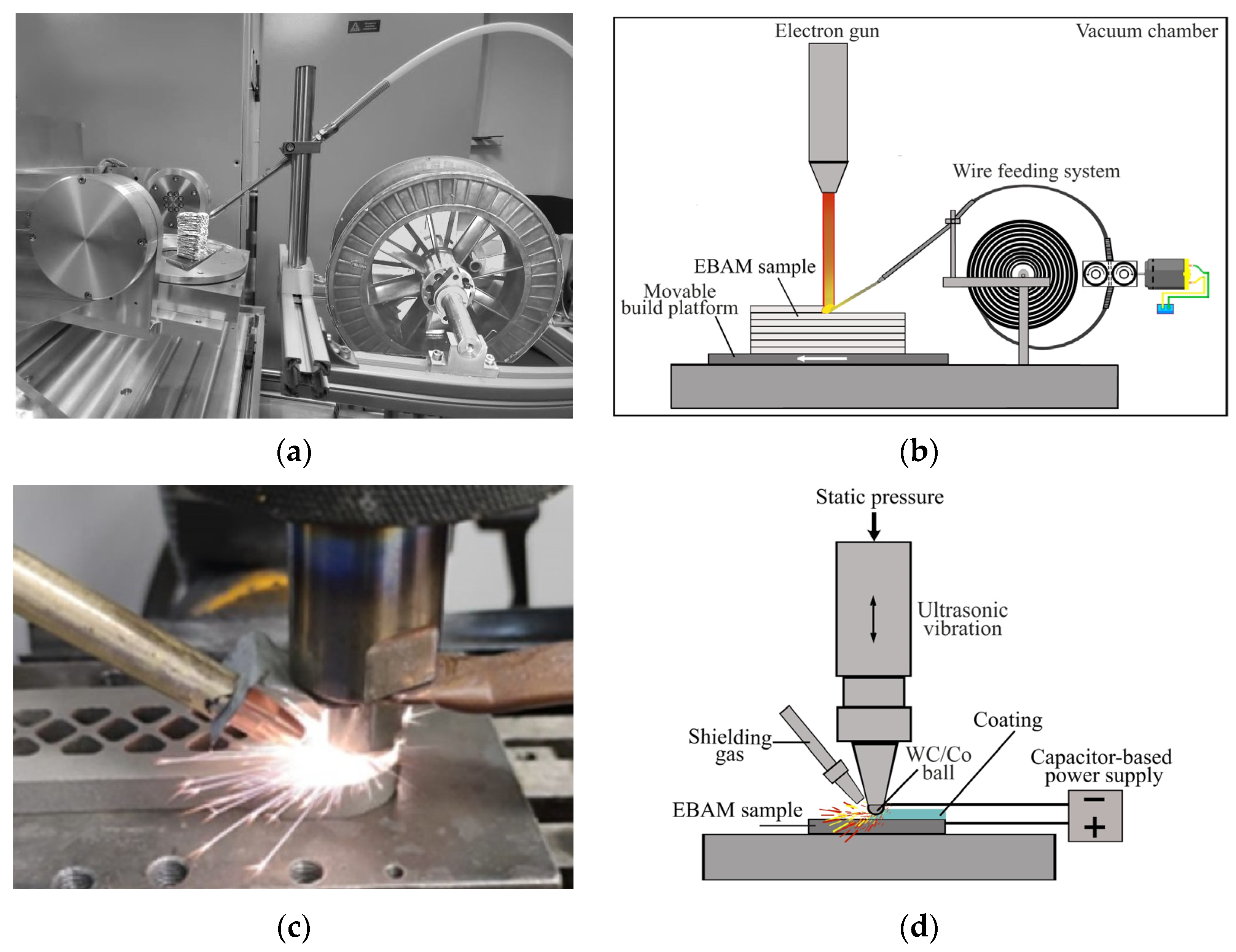
Table 1) using a wire-feed electron beam additive manufacturing (EBAM) setup (Figure 1a,b), developed in ISPMS SB RAS (Tomsk, Russia). Its thermo-cathode electron gun was operated at an accelerating voltage of 30 kV. The distance between the gun and a wrought titanium baseplate (150 × 150 × 10 mm) was 300 mm. The wire with a diameter of 1.6 mm was front-fed at a feed rate of 2 m/min and an angle of 35° to the baseplate. 22 layers were deposited, each 3.2 mm thick. The first three layers were formed at a beam current of 22 mA, followed by its decreasing down to 18 mA. 3D printing of the samples was performed by the build platform movement relative to the electron beam according to the meander scanning strategy at a speed of 4 mm/s. The hatch spacing between successive beads in the same layer was ~3 mm. After depositing each layer, the build platform was lowered by 3 mm. After the fabrication the 3D printed bars, 25 × 2 × 70 mm samples were cut out from them with a ‘Dk7720 CNC EDM Wire Cutting Machine’ (Taizhou Terui CNC Machine Co., Ltd., Taizhou, China). The chemical composition of the as-built EBAM Ti-6Al-4V samples is given in Table 1 as well. According to Table 1, the samples are characterized by the decreased amount of aluminum. It is well-documented that the evaporation of the volatile elements (most likely Al) is attributed to EBAM process [25,26].
Some EBAM Ti-6Al-4V samples were subjected to the UIT or UIET procedures. Initially, the samples had been ground and polished with SiC abrasive papers, as well as cleaned ultrasonically to remove the recast layer formed during electrical discharge machining. The UIT procedure was carried out using a WC-6%Co spherical striker 10 mm in diameter, rigidly fixed to the tip of an ultrasonic horn oscillating at a frequency of 22 kHz. An oscillation amplitude and an impact load of the striker were 40 μm and 200 N, respectively. The UIT procedure was performed in a row-by-row manner, so that the striker moved along the plate, similar to a typewriter, at a speed of 2 mm/s. The EBAM Ti-6Al-4V sample surface was repeatedly treated in five passes. An image of a self-developed UIT device was shown in [27]. It worth noting that the processing parameters were the same as in the previous work [27,28]. This make it possible to compare the surface finish, microstructure and phase composition of pure titanium, as-cast and EBAM-fabricated Ti-6Al-4V titanium alloys subjected to UIT.
The UIET procedure was conducted as follows. The EBAM Ti-6Al-4V sample and the WC-6%Co striker were connected to the positive and negative poles of a capacitor-based power supply, respectively (Figure 1c,d). Due to the striker oscillation, an electric discharge periodically occurred at the breakdown distance causing the material transfer from the eroded WC-6%Co striker to the EBAM Ti-6Al-4V sample. The following UIET parameters were preset: an output voltage of 40–80 V, a pulse current amplitude of 500 A, a pulse duration of 30 μs, and a frequency of 300 Hz. Both shielding conditions, in air and in argon 99.99% purity, were applied to protect the treated area of the EBAM Ti-6Al-4V samples from contamination with atmospheric gases.
After the UIT and UIET procedures, the surface morphology of the EBAM Ti-6Al-4V samples were investigated using a ‘New View 6200 3D’ optical profiler (Zygo Corp., Middlefield, CT, USA). An ‘Axiovert 40 Mat’ optical microscope (OM; Carl Zeiss, Göttingen, Germany) and an ‘Apreo 2 S’ scanning electron microscope (SEM; Thermo Fisher Scientific, Waltham, MA, USA) equipped with a ‘Pegasus’ integrated energy dispersive X-ray spectrometry (EDS)/electron backscatter diffraction (EBSD) system (Oxford Instruments, High Wycombe, UK) were employed for the microstructural characterization of the samples using both plan view and cross section geometries. For the EBSD analysis, the samples had been subjected to mechanical grinding and polishing followed by etching with Kroll’s reagent. The EBSD characterization was performed with a tungsten cathode at an accelerating voltage of 20 kV. Data acquisition was performed with a step size of 0.02–0.50 μm.
The phase composition of the EBAM Ti-6Al-4V samples were investigated with a ‘Shimadzu XRD-7000’ X-ray difractometer (XRD; Shimadzu Corporation, Kyoto, Japan) using CuK radiation at a wavelength of 1.5406 Å in the Bragg–Brentano geometry from 30 to 80° with a scan speed of 1.2 grad/min.
Vickers microhardness distributions were measured on cross-sections of the EBAM Ti-6Al-4V samples with a ‘PMT-3’ tester (LOMO, St. Peterburg, Russia) at a load of 50 g and a holding duration of 10 s. Five repeated tests were performed on every local investigated area. The Young’s modulus values were assessed using a ‘NanoTest’ system (Micro Materials Ltd., Wrexham, UK) in the load control mode with a Berkovich diamond tip at a maximum load of 50 mN.
Dry sliding friction tests were carried out according to the ‘pin-on-disk’ scheme at a load of 5 N (the calculated contact pressure Pmax was 31.8 MPa) and a sliding speed of 25 mm/s. A ‘CSEM CH-2000’ tribometer (CSEM Company, Neuchâtel, Switzerland) was applied in accordance with ASTM G99. A ball 6 mm in diameter from the 100Cr6 hardened bearing steel were used as a counterpart. Testing distances varied from 0.1 up to 6.0 km, while a tribological track radius was 16 mm. Friction coefficients were continuously recorded with an on-line data acquisition system attached to the tester.
Prior to the tribological tests, to remove a surface roughness of cut pieces proceed by EDM Wire Cutting Machine, the as-built EBAM Ti-6Al-4V sample had been wet-ground with SiC abrasive papers at progressive grades followed by polishing using a diamond paste. After polishing, the samples were thoroughly cleaned with ethyl alcohol in an ultrasonic bath for 15 min and dried in hot air then. The EBAM Ti-6Al-4V samples subjected to both UIT and UIET procedures had not been pretreated. The wear mechanism of the EBAM Ti-6Al-4V samples was investigated through observation of the wear track surfaces with a ‘Carl Zeiss EVO 50’ SEM (Carl Zeiss, Oberkochen, Germany). Wear volume losses were measured using a ‘KLA-Tencor Alpha-Step IQ’ stylus profilometer (KLA Instruments, Milpitas, CA, USA).

3. Results

3.1. The Microstructure of the As-Built EBAM Ti-6Al-4V Sample

The microstructure of the as-built EBAM Ti-6Al-4V samples consisted of non-equiaxed primary β grains, the average longitudinal and transverse sizes of which were 1.0 and 0.5 mm, respectively (Figure 2a). Inside the primary β grains, misoriented α/α’-Ti laths were observed with transverse dimensions from 1 to 2 µm (Figure 2b,c). Between the α/α’-Ti laths, the residual β phase was found, which possessed both lamellar and globular morphologies (Figure 2c). According to the EBSD data, the volume fraction of the residual β phase was 8%. The results of the SEM studies of the EBAM Ti-6Al-4V samples were described in detail previously [29].

3.2. The Microstructure of EBAM Ti-6Al-4V Sample Subjected to UIT

During the UIT process, alternating tracks 300 µm wide were formed on the surface of the EBAM Ti-6Al-4V sample (Figure 3a and Figure 4a). They consisted of periodic semicircular protrusions due to plastic displacement of the material from the contact zone behind the striker. Dimensions of the tracks were determined by the striker diameter, the impact force, hardness of the material being processed, as well as by the trajectory of the striker movement along the sample surface. In turn, the distance between the semicircular protrusions, which was dependent on the frequency of impacts and the striker movement speed, was 10 μm, corresponding to that between two adjacent impact centers. The root mean square roughness of the EBAM Ti-6Al-4V sample surface increased from 0.05 to 0.4 µm as a result of UIT process. The surface roughening mechanism for titanium samples during the UIT process was described in detail previously [30].
SEM images of both surface and side face of the EBAM Ti-6Al-4V sample subjected to UIT, obtained with the back-scattered electron detector, showed that the microstructure of the modified surface layer, 10 µm thick, consisted of bended α/α′-Ti laths (Figure 4b,c). Their random bending was due to the striker reverse movement during the UIT procedure. The transverse size of the α/α′ phase laths did not exceed 500 nm. An EBSD orientation map clearly demonstrated their intense fragmentation (Figure 4d).

3.3. The Microstructure of the EBAM Ti-6Al-4V Sample Subjected to UEIT in Air

During the UIET process in air, plastic deformation of the EBAM Ti-6Al-4V sample surface had been accompanied by periodic breakdowns of the air gap between it and the striker. The generation of pulsed spark discharges had caused intense heat release in the contact spots overlapping each other. As a result, a coating was formed on the treated surface due to the predominant electrical erosion of the WC-6%Co striker. Spattering of the liquid metal at the cathode spot of the spark discharges had caused a discrete inhomogeneous relief of the coating with areas of the spattered and solidified striker material (Figure 3b). The average size of such droplets was 80 µm. The root mean square roughness of the coating produced by the UIET process in air reached 3.8 µm. According to the EDS analysis results, the coating contained tungsten, cobalt, carbon and oxygen along with titanium, aluminum and vanadium (Table 2). After the five-pass UIET procedure, the average coating thickness was ~10 µm.
On the EBAM Ti-6Al-4V sample subjected to UIET in air, the coating surface was characterized by the presence of a large number of melted areas containing cavities, pores and cracks (Figure 3b and Figure 5a). At the same time, a SEM image of the side face showed a uniform and dense coating structure (Figure 5b). Microcracks, cavities and chains of pores between individual layers of the coating were observed in some regions (Figure 5c). Also, a nonplanar interface between the coating and the Ti-6Al-4V substrate should be noted. As followed from Figure 6, the coating microstructure consisted of globular particles with an average size of 250 nm. According to an EBSD phase map (Figure 6b), the coating contained the WC, W2C, β-(W, Ti)C and TiO2 phases.

3.4. The Microstructure of the EBAM Ti-6Al-4V Sample Subjected to UEIT in Argon

The UIET procedure in argon resulted in the formation of a dense, continuous and thick (~20 µm) coating on the EBAM Ti-6Al-4V sample surface (Figure 7a,b). It was also characterized by a developed surface due to spattering of the liquid metal (Figure 3c). In this case, the average size of solidified droplets on the coating surface was 120 μm. A large number of pores and cracks were observed on the droplet surfaces as well. The value of root mean square roughness of the coating produced by the UIET in argon does not exceed 3.2 μm.
The microstructure of the coating formed on the EBAM Ti-6Al-4V sample surface during the UIET procedure in argon also consisted of particles with dimensions of 1–3 µm (Figure 8a,b). The main coating phases were the WC, β-(W, Ti)C and α-Ti ones (Figure 8b). Moreover, the coating contained regions with a size of 150 μm (highlighted by a dotted line in Figure 8a), including misoriented colonies of the α/α′ phase laths and cubic WC particles (Figure 9). The average transverse size of the α/α′ phase laths was 2 µm, while the W2C particle dimensions varied from 1 up to 3 µm. In addition, interlayers of the residual β-Ti phase were revealed on an EBSD phase map of such an area (Figure 9c).
A distinctive feature of the coating formed by the UIET procedure in argon was the absence of oxygen (Figure 10). In addition, the coating contained half as much tungsten as compared to that formed in the UIET process in air (Table 2).

3.5. The Microstructure of the EBAM Ti-6Al-4V Sample Subjected to UEIT in Argon

An XRD pattern of the as-built EBAM Ti-6Al-4V sample showed peaks corresponding to different crystallographic planes of the α-Ti phase, as well as a separate pronounced diffraction peak corresponding to the β-Ti (110) one (Figure 10a; curve 1). The volume fraction of the β-phase was 4.5% (Table 3). The lattice parameters of the α phase in the as-built EBAM Ti-6Al-4V sample are presented in Table 4.
Severe plastic deformation of the surface layer on the EBAM Ti-6Al-4V sample during the UIT process manifested itself in the formation of the predominant (002) orientation of the α phase (Figure 10a; curve 2). The volume fraction of the β-Ti phase almost did not change (Table 3). As followed from Table 4, the UIT process resulted in an increase in the c/a ratio of the α-Ti phase compared to that for the as-built sample. This fact could be related to the saturation of the EBAM Ti-6Al-4V sample surface with oxygen during the UIT process. The presence of oxygen in Ti-6Al-4V samples subjected to UIT was demonstrated in [27,29].
The intensity of X-ray peaks corresponding to both α-Ti and β-Ti phases decreased significantly on the XRD pattern of the coating formed on the EBAM Ti-6Al-4V sample surface during the UIET procedure in air (Figure 10a; curve 3). Their volume fractions were 29.2 and 2.2, respectively (Table 3). At the same time, broad peaks appeared at the 2θ angles, approximately equal to 37.1, 43.2, 62.4 and 73.9°, corresponding to the WC1–x phase. Moreover, pronounced ones were observed at the 2θ angles equal to 40.6, 58.8 and 73.2°, corresponding to the W phase. As followed from Figure 10b, broadening of the peak located at the angle of 37.1° was associated with the superposition of the (111) (W, Ti)C1−x and (111) WC1–x peaks. In turn, asymmetric broadening of the peak located in a range of the 2θ angles from 39 to 42° reflected the presence of the closely located (110) β-Ti, (102) α-Ti and (110) W peaks. Finally, broadening of the peak at the 2θ angle approximately equal to 43.2° was connected with the presence of the closely spaced ones of the (200) (W, Ti)C1−x and (200) WC1–x phases. It should be noted that the presence of the TiO, CoO, and W2(CO) oxide phases could not be completely ruled out. However, these phases were very difficult to unambiguously identify due to their close position with the (W, Ti)C1–x and WC1–x phases.
In the coating formed on the EBAM Ti-6Al-4V sample surface during the UIET procedure in argon, the α-Ti, β-Ti and W phases were also found in addition to the β-(W,Ti)C1–x and WC1–x FCC solid solution (Figure 10a; curve 4). A distinctive feature of this coating was high both volume fractions of the α-Ti and, especially, β-Ti phases (Table 3). Broadening the peaks at the 2θ angles equal to 37.1 and 43.2° was still observed, due to the presence of the closely spaced ones of the (W, Ti)C1–x and WC1–x phases (Figure 10c).

3.6. The Microhardness Tests

As followed from Figure 11, microhardness of the surface layer on the EBAM Ti-6Al-4V sample subjected to UIT was 7.5 GPa. With rising distance from the surface, microhardness values decreased and reached the base metal level of 4.8 GPa at a depth of 30 μm.
Microhardness of the coating formed on the EBAM Ti-6Al-4V sample surface during the UIET procedure in air reached 26 GPa (Figure 11; curve 2). At a depth of ~10 µm under the coating, the microhardness values sharply reduced down to 6 GPa. As the depth increased from 20 to 40 μm, the microhardness levels gradually decreased down to 4.8 GPa.
After the UIET procedure in argon, the maximum microhardness values of the coating did not exceed 16 GPa (Figure 11; curve 3). Under the coating, a gradient microhardness decrease was also observed. In this case, the total thickness of the hardened surface layer reached 60 μm.

3.7. The Tribological Tests

Due to the intense adhesive interaction of the as-built EBAM Ti-6Al-4V sample with the 100Cr6 bearing steel counterpart, a thin transfer layer had been formed on the pin surface from the very beginning of the tribological test (Figure 12a). Intense deformation of the transfer layer and its local heating at the contact area had caused hardening and embrittlement of the transferred material. During the tribological test, the transfer layer on the counterpart had been repeatedly fractured and re-formed. The presence of hard debris particles in the contact (Figure 12b) had resulted in the intense abrasive wear of the as-built EBAM Ti-6Al-4V sample, which manifested itself in the formation of a regular grooved relief of the wear track surface (Figure 12c,d), as well as its rough profile (Figure 13a).
During the tribological test, the fatigue damage accumulation in the surface layer of the as-built EBAM Ti-6Al-4V sample caused a gradual decrease in its cohesive strength. Figure 12, clearly shows the material pull-out traces on the wear track surface, which had been formed as a result of sticking of the contacting surfaces. Rising the transfer layer thickness and, consequently, both size and number of debris particles, had caused a continuous increase in the material volume loss (Figure 13a and Figure 14a; curve 1). The friction coefficient of the as-built EBAM Ti-6Al-4V samples was ~0.4 (Figure 14b; curve 1), which was in good agreement with that for Ti-6Al-4V samples fabricated by electron beam melting [31].
The UIT procedure slightly enhanced the wear rate of the EBAM Ti-6Al-4V sample. A sharp increase in the material volume loss started immediately after the beginning of the tribological test (Figure 14a; curve 2). Comparison of Figure 13a,b enabled to conclude that the wear track depth on the as-built EBAM Ti-6Al-4V samples and the one subjected to UIT were 25 and 35 µm, respectively, at a sliding distance of 60 m. The UIT procedure did not affect the abrasive wear mechanism of the EBAM Ti-6Al-4V sample. In the tribological test, debris particles had been either carried out from the contact, accumulating along its edges, or reattached to one of the friction surfaces. Part of debris particles remaining in the contact had been transferred along the wear track and smeared over its surface (Figure 15), while the other part had formed a transfer layer on the sample due to the adhesive interaction with the counterpart.
A dependence of the friction coefficient for the EBAM Ti-6Al-4V sample subjected to UIT on the sliding distance is shown in Figure 14b (curve 2). Due to the presence of a folded relief, which had caused a decrease in the actual contact area, the friction coefficient was 0.08 at the sliding distance of 10 m. With its rising, the friction coefficient quickly reached its stationary level, equal to ~0.4.
The UIET procedure in air led to a significant decrease in the wear rate of the EBAM Ti-6Al-4V sample (Figure 14a; curve 3). As followed from Figure 13c, the wear track depth did not exceed 0.5 μm even at a sliding distance of 3 km. With its rising up to 4 km, roughness of the wear track profile increased significantly that was associated with partial chipping of the coating, which enhanced the material volume loss in the test (Figure 14a; curve 3). Finally, when the wear track depth of 20 μm exceeded the coating thickness at a sliding distance of 6 km, roughness of the wear track profile decreased again. In this case, the material value loss had grown exponentially during the tribological test.
An analysis of SEM images of the wear track surface on the EBAM Ti-6Al-4V sample subjected to UIET in air showed that the rough coating surface had been initially smoothed out during the tribological test. Then, it had been gradually crumbled and chipped (Figure 16a,b). Thicknesses of such chipped fragments varied within 1–2 µm. Only at the sliding distance of 6 km, a grooved relief was observed of the wear track surface, caused by wearing of the EBAM Ti-6Al-4V substrate (Figure 16c,d).
Figure 14b (curve 3) shows a dependence of the friction coefficient on the sliding distance for the coating formed on the EBAM Ti-6Al-4V sample in the UIET procedure in air. The initially low value of the friction coefficient (less than 0.2) was associated with the high surface roughness, while gradual smoothing of the wear track surface was the reason for it rising to the stationary level of ~0.5. This value was maintained until the sliding distance did not exceed ~6 km. Then, the friction coefficient decreased down to ~0.4 when the wear track depth exceeded the coating thickness.
Wear resistance of the EBAM Ti-6Al-4V sample subjected to UIET in argon was significantly lower. According to Figure 13d, the rough profile of the wear track surface, caused by chipping of individual coating fragments (Figure 17a), was observed already at the sliding distance of 1 km. When it reached ~2 km, the material volume loss increased sharply (Figure 14a). At the same time, roughness of the wear track profile enhanced greatly due to intense warping and chipping of the coating (Figure 17b). Finally, the wear track depth was commensurate with the coating thickness at the sliding distance of 3 km (Figure 13d). Some areas with a grooved relief, characteristic of the worn Ti-6Al-4V substrate surface, became visible on the wear track (Figure 17c,d).
Due to the high surface roughness of the coating formed by the UIET procedure in argon, its friction coefficient also did not exceed ~0.2 at the run-in stage and began to increase up to ~0.5 only at a sliding distance of ~200 m (Figure 14b; curve 4), i.e., much later than in the case of the coating formed in air. The stationary level of the friction coefficient, equal to ~0.5, was achieved only at a sliding distance of ~500 m.

4. Discussion

In the UIET procedures, spark discharges occurred periodically between the WC-6%Co striker and the EBAM Ti-6Al-4V samples, which quickly heated adjacent zones on both surfaces up to their melting points. In this case, the molten WC-Co material was transferred from the striker into the interelectrode space and the sample surface. During the process of separation from the striker (anode), transferred drops had time to heat up to high temperatures, boil and explode. At the same time, the melt splashed out of craters, formed on the sample (cathode) surface under the action of plasma pressure from the cathode spot during a spark discharge. Typically, the melt displacement process had been accompanied by the formation of microjets that had disintegrated into microdroplets [32], which were observed on the coating surface. The striker impacts into the molten surface layer on the sample not only promoted the liquid metal displacement from the craters, but also caused hydrodynamic mixing of both (WC-6%Co and Ti-6Al-4V) materials. In addition, the repeated UIET action provided additional forging of the solidified coatings, increasing their density and uniformity.
In the UIET process in air, both molten materials had actively adsorbed atmospheric gases. As a result, the complex composite coating based on the three-phase WC-TiC-Co alloy had been formed on the sample surface, which included elements from the processing tool, the substrate and the interelectrode medium, as well as some compounds formed via reactions between these chemicals at high temperatures. In particular, the W and WC1–x phases had been formed as a result of decarburization of tungsten carbide particles upon their interaction with titanium [33]. In turn, the formation of the FCC β-(W, Ti)C1–x solid solution was caused by the incorporation of tungsten into the titanium carbide lattice [34]. According to the EDS data, the oxygen content in the coating formed during the UIET process in air was 7.7 wt.%, which also indicated that the molten metal had actively reacted with the environment. Most likely, the adsorption of gas molecules was the reason for the formation of pores at the interface between individual coating layers resulting from the multi-pass UIET procedure.
The presence of argon in the interelectrode space had protected the EBAM Ti-6Al-4V sample surface from the contamination with oxygen from air. In the coating formed by the UIET procedure in argon, oxygen was not observed and the number of pores decreased. In addition, due to the higher ionization ability of argon, the conductivity between the sample and the striker had increased, rising the number of spark discharge pulses. A decrease in the breakdown voltage in argon compared to that in air [35] had caused an increase in spark discharge energies, which had contributed to a more intense melting of both the WC-6%Co striker and the Ti-6Al-4V sample. As a result, the coating thickness was twice as large after the UIET procedure in argon than that in air.
Due to the higher titanium content, the coating based on the three-phase WC-TiC-Co alloy. mainly consisting of coarse β-(W, Ti)C1–x grains, are formed on the EBAM Ti-6Al-4V sample surface after the UIET procedure in argon, while finer ones from both tungsten and titanium-tungsten carbides, as well as titanium oxide were observed after the same process in air. Obviously, the dimensions of the carbide grains in the coatings had been controlled by the degree of their wetting by the WC-Co melt. Thus, the perfect wettability of tungsten carbide with liquid cobalt had provided the fine-grained structure of the coating formed in air. At the same time, the titanium-tungsten carbide grains were more prone to the secondary recrystallization process, providing the formation of the coarse-grained structure of the coating formed in argon.
It was due to the intense liquid metal spattering from craters on the EBAM Ti-6Al-4V sample surface that a great number of solidified titanium droplets containing large W2C particles had been formed in the coating during the UIET process in argon. The microstructure of such droplets consisted of misoriented colonies of the α/α′-Ti laths separated by the β phase interlayers. According to the data of X-ray diffraction analysis, the volume fraction of the β-Ti phase reached 18.7% in the coating formed during the UIET process in argon. Such a high β phase content was obviously associated with the presence of cobalt in the titanium droplets, which was a β-stabilizing element.
The gaseous interelectrode medium had a significant effect not only on the thickness of the coatings formed during both UIET procedures, but also on their microhardness. It could be assumed that the presence of the oxide phases along with the W2C and (W, Ti)C1–x carbides was the main reason for the higher microhardness of the coating formed by the UIET procedure in air. In this case, the presence of oxygen was confirmed by the high c/a ratio of the α-Ti phase (Table 4), which acted as a metal binder. On the contrary, the coating formed in argon was characterized not only by the greater volume fractions of the α-Ti and β-Ti phase, but also by lower microdistortions of the α-Ti crystal lattice caused by the presence of interstitial atoms. This assumption was based on the fact that the c/a ratios of the α-Ti phase were similar in the coatings formed in argon and in the as-built EBAM Ti-6Al-4V sample. As a consequence, microhardness of the coating formed in the UIET process in argon was lower.
The initial moment of the contact interaction between the counterpart and the EBAM Ti-6Al-4V sample could be described in terms of the Hertz problem for the contact of a ball and an elastic half-space. In this case, the a contact spot radius depended on the reduced elastic modulus of the counterpart–sample system and its relative curvature as follows [36]:
a = ( 3 F n R 4 E * ) 1 / 3 ,
where Fn was the normal compressive load; E * = ( 1 v 1 2 E 1 + 1 v 2 2 E 2 ) 1 was the reduced elastic modulus of the counterpart-sample system (E1, E2 and υ1, υ2 were Young’s moduli and Poisson’s ratios of the counterpart and the sample, respectively); 1 R = 1 R 1 + 1 R 2 was its relative curvature (R1 and R2 were the curvature radii of the counterpart and the sample, respectively). Since the EBAM Ti-6Al-4V sample surface was considered to be macroscopically flat, that was, its curvature was zero, then R in Formula (1) was equal to the counterpart radius. In this case, the average compressive stress in the indentation region of the counterpart in the EBAM Ti-6Al-4V sample was calculated as follows [36]:
σ a v = F π a 2 = ( 16 F E * 9 π 3 R 2 ) 1 / 3 .
According to the nanoindentation data, the elastic modulus values of the as-built EBAM Ti-6Al-4V sample, as well as the ones subjected to UIT and UIET, were 130, 135 and 194 GPa, respectively. The calculation results made it possible to conclude that the level of average compressive stresses was 275 MPa for the as-built EBAM Ti-6Al-4V sample, while they were 280 and 330 MPa at the contact area during the UIT and UIET processes, respectively. Upon both procedures, in the indentation center at a depth of ~0.14R (where R was the counterpart radius) [37], the σmax maximum compressive stresses were 3/2 times higher than their σ average level [36], remaining significantly below the yield point of the Ti-6Al-4V alloy.
After applying a tangential force to the counterpart, causing it to move along the EBAM Ti-6Al-4V sample surface, the combination of normal and tangential loads led to the accumulation of contact fatigue damage [37] in the treated surface layer, as well as to the formation of a frictional transfer layer on the counterpart surface due to the intense adhesive interaction. In general, wear of all studied EBAM Ti-6Al-4V samples was the result of a complex combination of its different mechanisms (abrasive, adhesive and fatigue), developed under the influence of many factors. Thus, the high wear rates of both as-built EBAM Ti-6Al-4V sample and the one after the UIT procedure were caused by the stronger effect of the abrasive mechanism compared to the others. The formation and detachment of debris particles were associated with the rotational-shear nature of plastic flow in the sample surface layers. The development of rotational deformation modes occurred due to the moments of tangential forces oriented parallel to the sliding direction and the gradient of internal friction stresses in the coating [38]. This caused the rotation of local fragments of the surface layer, which, in combination with the high friction coefficients, contributed to the intensive formation of debris particles.
The analysis of the SEM images of the wear tracks (Figure 15) enabled to conclude that the material transfer from the EBAM Ti-6Al-4V sample surface subjected to UIT to the counterpart was uneven. During the tribological test, the material accumulated predominantly in the front of the counterpart, i.e., debris particles were collected by the counterpart in the process of its movement in the area of compressive stresses. Then, the debris particles were crushed, smeared and fixed on the counterpart (Figure 15b,c), forming a transfer layer. After its formation, the chemical compositions of the sliding surface layers became similar, which caused rising the molecular component of the friction force and an increase in the role of the adhesive interaction between the counterpart and the sample. Due to high contact stresses and the similar chemical compositions of the sliding surfaces, microcontact sticking of their local areas could occur. In the process of relative movement of the sliding surfaces relative to each other, the transfer layer was fractured and re-formed many times, causing the friction coefficient deviation.
The refinement and bending of the α/α′-Ti laths, a high dislocation density inside the martensitic laths, and the great crystal lattice distortions due to the presence of interstitial atoms caused the increase in the microhardness values of the EBAM Ti-6Al-4V sample subjected to UIT, but led to the simultaneous slight reducing its wear resistance. It is generally accepted that the tribological behavior of metal and its alloys including Ti-6Al-4V titanium alloy is governed by the structure refinement. However, the numerical, experimental and simulations results have shown that the anticipated correlation between hardness and wear is limited because of various complicating factors that influence the wear behavior [39]. In particular, no qualitative differences in surface topography were observed among the worn surfaces of the course-grained and ultra fine grained Ti after wear [39]. On the other hand, despite the higher microhardness of ultra fine grained titanium, the total amount of fretting wear in this state is twice that for course-grained titanium due to the high density of high energy non-equilibrium grain boundaries [40]. According to [40], the grain boundaries are a source of defects and places of destruction, and their multiple intersections lead to increased wear. Most likely, the increase in the wear rate of the hardened surface layer of the EBAM Ti-6Al-4V sample subjected to UIT was associated with the presence of hard debris particles formed by plastic deformation of hardened surface layer. Moreover, it can be expected a more intense formation of debris particles due to the initiation and propagation of surface microcracks on the sample during the tribological test. According to the Zener-Straw model [41], interfacial boundaries and dislocation clusters were the cause of a high concentration of shear stresses. When the maximum shear stress reached a critical value, two dislocations located at the top of such a cluster, resulting in the formation of a microcrack nucleus, into which other dislocations spontaneously flew, causing its propagation.
In our previous work [29] the microstructure, deformation and fracture mechanisms of the wire-feed EBAM Ti-6Al-4V samples subjected to UIT followed by uniaxial tension was studied. The experimental observation and molecular dynamic simulation evidenced that, since dislocation sliding in the ultrasonically treated surface layer of the wire-feed EBAM Ti-6Al-4V samples was hindered, the non-crystallographic shear bands nucleated in the underlying layers propagated in the ultrasonically treated surface layer. It can be expected that during the wear of the samples, numerous shear bands are formed beneath the wearing surface along the sliding direction and, in addition, cracks were initiated along the shear bands [39]. Similar simultaneous increase in hardness and decrease in wear resistance of aluminum-based alloys after processing by equal channel angular pressing due to the lack of a strain hardening capability was observed in Ref. [42].
The absence of a grooved relief on the wear track surfaces of the hard coatings formed in both UIET procedures indicated their predominant fatigue damage in the tribological tests. The fatigue wear process was typically connected with repeated stress cycles in the contact area, namely, the development of compressive and tensile stresses in front and behind the moving counterpart, respectively. Depending on the ratio of the normal and tangential components of the contact forces, as well as the structure of the material and its physical and mechanical properties, a primary microcrack could initiate both on the surface and in the subsurface layer. In the first case, depressions on the coating rough surface acted as crack nuclei. Moreover, the longer was the crack nucleus length (the cavity depth), the higher was the stress concentration at its tip. In the second case, pores, inclusions, as well as the interface between the coating and the substrate served as the crack initiation spots.
In the performed experiments, the coating on the EBAM Ti-6Al-4V sample, formed via the UIET process in air, demonstrated the maximum wear resistance. First of all, the reason was its very high microhardness due to the presence of small WC, W2C, (W, Ti)C and TiO2 inclusions. In this case, the propagation of a fatigue crack along the boundaries of fine carbide and oxide phases was accompanied by its branching, which resulted in the relaxation of stresses at its tip. Another key factor determining the improved wear resistance of the coating was the relatively low strength of the interface between its individual layers due to the presence of pores. In the tribological test, fatigue cracks, initiating on the developed coating surface, propagated deeper to the nearest interface, deviating along it then. As a result of the adhesive interaction with the counterpart, these fragments were pulled out and transferred along the direction of its movement. The path deflection for the propagating fatigue crack contributed to the gradual increase in the material volume loss. As followed from Figure 13, each individual coating layer was removed at the sliding distance of 1 km.
Microhardness of the coating formed on the EBAM Ti-6Al-4V sample in the UIET process in argon was significantly lower. The reason was the presence of larger WC and β-(W, Ti)C phase particles, as well as solidified droplets, consisting of both α-Ti laths and β-Ti interlayers. As a result, the noticeable increase in the material volume loss began already at the sliding distance of 2 km. Moreover, this coating was quickly worn out, as it consisted of large (Ti, W)C grains separated by cobalt and small tungsten carbide inclusions. Obviously, in the absence of pores at the interfaces between individual layers, a fatigue crack, initiating on the surface, easily propagated through the (Ti, W)C grains deep into the brittle coating. Upon reaching the ductile substrate, the crack deviated along the coating/substrate interface, pulling out coating fragments. Their fracture led to the formation of hard debris particles in the contact area, which had an intense abrasive effect on the substrate. Along with this, pulling out large fragments of the coating caused a decrease in the area of its contact with the counterpart, and, consequently, an increase in the contact pressure on the sample. The combined action of all these factors resulted in rapid abrasion of the coating.
Finally it should be note that the higher wear rate is not always correlated with higher friction coefficient. The friction coefficient is a tribosystem property and not materials related. Therefore the normal load and sliding velocity only govern the friction coefficient, while for the wear behavior it necessary to consider surface roughness, hardness, adhesion, wear debris temperature, normal load and also sliding velocity. Despite the high friction coefficient, the extremely high hardness is the main reason for the better wear resistance of the EBAM Ti-6Al-4V samples subjected to UIET in air and argon. It is interesting to mention at this point that high velocity oxygen fuel spray process enable to produce WC-(nano WC-Co) coatings composed of micro-sized WC strengthening phase and nano WC strengthened cobalt matrix [43]. A similar simultaneous increase in friction coefficient and wear resistance of the WC-(nano WC-Co) coatings was observed.

5. Conclusions

To increase the wear resistance the wear resistance of Ti-6Al-4V samples fabricated by wire-feed electron beam additive manufacturing a method based on a combination of ultrasonic impact treatment with electrospark alloying was used. UIET process was carried out in air and in argon atmosphere to make coatings denser and thicker. The microstructure, phase composition, as well as the mechanical and tribological properties of the EBAM Ti-6Al-4V samples, including those subjected to the UIP and UIEP processes, were investigated and the principles conclusions can be drawn as follows:
The results of the SEM and EBSD examinations showed that the microstructure of the as-built EBAM Ti-6Al-4V sample consisted of large unequal primary β grains. Inside them, α/α′-Ti laths 0.5–1.5 µm in sizes, separated by residual β phase layers, were found. The UIT procedure resulted in thinning and bending of the α/α′-Ti laths in the thin (10 µm) surface layer of the EBAM Ti-6Al-4V sample. The XRD analysis did not reveal a significant change in the β-Ti volume fraction, while the increase in the ratio c/a of the α-Ti phase was observed. This phenomenon could be associated with the saturation of the sample surface with oxygen during the UIT process.
The UIET procedure in air with the WC-6%Co striker enabled to deposit the ~10 µm thick coating, based on the three-phase WC-TiC-Co alloy. It consisted of fine grains of both tungsten and titanium-tungsten carbides, as well as titanium oxide. As a result of the UIET process in argon, the denser and thicker (~20 μm) coating was formed, which mainly included coarse β-(W, Ti)C1–x grains. Moreover, a large number of solidified titanium-based droplets, containing large W2C particles, were observed in this coating. The microstructure of the droplets consisted of misoriented colonies of the α/α′-Ti laths separated by the β phase interlayers.
Microhardness of the as-built EBAM Ti-6Al-4V sample was 4.8 GPa. The UIT procedure caused its rising up to 7.5 GPa in the surface layer. After the UIET procedures in air and argon, the microhardness levels were 26 and 16 GPa, respectively.
Despite the presence of the hardened surface layer, no increase in wear resistance of the EBAM Ti-6Al-4V sample was recorded after the UIT procedure. Moreover, the enhanced wear rate of this modified surface layer was observed in the tribological test according to the ‘pin-on-disk’ scheme. On the contrary, the UIET process was an effective way to improve wear resistance of the EBAM Ti-6Al-4V sample. The coating formed in air was characterized by the maximum wear resistance, since it was completely worn out at the sliding distance of 6 km, while the wear rate was twice as fast for the one deposited in argon.

Author Contributions

Conceptualization, A.P.; formal analysis, A.P. and M.K.; methodology, K.K., D.B. and S.M.; investigation, M.K., K.K., D.B., L.K., S.M. and E.S.; data curation, E.S.; writing—original draft preparation, A.P.; writing—review and editing, A.P.; visualization, M.K., K.K., D.B. and L.K.; supervision, A.P.; project administration, A.P. All authors have read and agreed to the published version of the manuscript.

Funding

The work was performed according to the Government research assignment for Institute of Strength Physics and Materials Science (ISPMS) SB RAS, Project No. FWRW-2021-0010.

Data Availability Statement

The data presented in this study are available on request from the corresponding author.

Acknowledgments

The investigations have been carried out using the equipment of Share Use Centre “Nanotech” of the ISPMS SB RAS and the CSU NMNT TPU.

Conflicts of Interest

The authors declare no conflict of interest.

References

  1. Anil Kumar, V.; Gupta, R.K.; Prasad, M.J.N.V.; Narayana Murty, S.V.S. Recent advances in processing of titanium alloys and titanium aluminides for space applications: A review. J. Mater. Res. 2021, 36, 689–716. [Google Scholar] [CrossRef]
  2. Tal-Gutelmacher, E.; Eliezer, D. The hydrogen embrittlement of titanium-based alloys. JOM 2005, 57, 46–49. [Google Scholar] [CrossRef]
  3. Pramanik, A. Problems and solutions in machining of titanium alloys. Int. J. Adv. Manuf. Technol. 2014, 70, 919–928. [Google Scholar] [CrossRef]
  4. Wang, Z.; Xiao, Z.; Huang, C.; Weiwen, Z.; Zhang, W. Influence of Ultrasonic Surface Rolling on Microstructure and Wear Behavior of Selective Laser Melted Ti-6Al-4V Alloy. Materials 2017, 10, 1203. [Google Scholar] [CrossRef] [PubMed]
  5. Amanov, A.; Cho, I.-S.; Kim, D.-E.; Pyun, Y.-S. Fretting wear and friction reduction of CP titanium and Ti–6Al–4V alloy by ultrasonic nanocrystalline surface modification. Surf. Coat. Technol. 2012, 207, 135–142. [Google Scholar] [CrossRef]
  6. Wang, Z.; Liu, Z.; Gao, C.; Wong, K.; Ye, S.; Xiao, Z. Modified wear behavior of selective laser melted Ti6Al4V alloy by direct current assisted ultrasonic surface rolling process. Surf. Coat. Technol. 2020, 381, 125122. [Google Scholar] [CrossRef]
  7. Feng, S.; Tang, H.; Zhang, S.; Wang, H. Microstructure and wear resistance of laser clad TiB–TiC/TiNi–Ti2Ni intermetallic coating on titanium alloy. Trans. Nonferr. Met. Soc. China 2012, 22, 1667–1673. [Google Scholar] [CrossRef]
  8. Cui, W.; Qin, G.; Duan, J.; Wang, H. A graded nano-TiN coating on biomedical Ti alloy: Low friction coefficient, good bonding and biocompatibility. Mater. Sci. Eng. C 2017, 71, 520–528. [Google Scholar] [CrossRef] [PubMed]
  9. Aniołek, K.; Kupka, M.; Barylski, A. Sliding wear resistance of oxide layers formed on a titanium surface during thermal oxidation. Wear 2016, 356–357, 23–29. [Google Scholar] [CrossRef]
  10. Borgioli, F.; Galvanetto, E.; Iozzelli, F.; Pradelli, G. Improvement of wear resistance of Ti–6Al–4V alloy by means of thermal oxidation. Mater. Lett. 2005, 59, 2159–2162. [Google Scholar] [CrossRef]
  11. Man, H.; Bai, M.; Cheng, F. Laser diffusion nitriding of Ti–6Al–4V for improving hardness and wear resistance. Appl. Surf. Sci. 2011, 258, 436–441. [Google Scholar] [CrossRef]
  12. Mikhailov, V.V.; Gitlevich, A.E.; Verkhoturov, A.D.; Mikhailyuk, A.I.; Belyakov, A.V.; Konevtsov, L.A. Electrospark alloying of titanium and its alloys: The physical, technological, and practical aspects. Part I. The peculiarities of the mass transfer and the structural and phase transformations in the surface layers and their wear and heat resistance. Surf. Eng. Appl. Electrochem. 2013, 49, 373–395. [Google Scholar] [CrossRef]
  13. Levashov, E.A.; Zamulaeva, E.I.; Kudryashov, A.E.; Vakaev, P.V.; Petrzhik, M.I.; Sanz, A. Materials Science and Technological Aspects of Electrospark Deposition of Nanostructured WC-Co Coatings onto Titanium Substrates. Plasma Process. Polym. 2007, 4, 293–300. [Google Scholar] [CrossRef]
  14. Ruijun, W.; Yiyu, Q.; Jun, L. Interface behavior study of WC92–Co8 coating produced by electrospark deposition. Appl. Surf. Sci. 2005, 240, 42–47. [Google Scholar] [CrossRef]
  15. Wang, P.; Pan, Y.; Liu, Y.; Fu, X.; Li, H. Research on surface properties of Ti-6Al-4V alloy by multi-ultrasonic rolling. Proc. Inst. Mech. Eng. Part C J. Mech. Eng. Sci. 2021, 235, 5594–5602. [Google Scholar] [CrossRef]
  16. Wang, W.; Han, C. Microstructure and Wear Resistance of Ti6Al4V Coating Fabricated by Electro-Spark Deposition. Metals 2018, 9, 23. [Google Scholar] [CrossRef]
  17. Barile, C.; Casavola, C.; Pappalettera, G.; Renna, G. Advancements in Electrospark Deposition (ESD) Technique: A Short Review. Coatings 2022, 12, 1536. [Google Scholar] [CrossRef]
  18. Chigrinova, N.M.; Lovygin, S.I.; Chigrinov, V.E. Role of ultrasound in mechanisms of anode-cathode interactions during electrospark alloying. Sci. Tech. 2016, 15, 380–390. [Google Scholar] [CrossRef]
  19. Liu, Y.; Wang, D.; Deng, C.; Huo, L.; Wang, L.; Fang, R. Study on fabrication of ceramic coatings on Ti–6Al–4V alloy by combined ultrasonic impact treatment and electrospark. Surf. Eng. 2015, 31, 892–897. [Google Scholar] [CrossRef]
  20. Liu, Y.; Wang, D.; Deng, C.; Huo, L.; Wang, L.; Cao, S. Feasibility study on preparation of coatings on Ti–6Al–4V by combined ultrasonic impact treatment and electrospark deposition. Mater. Des. 2014, 63, 488–492. [Google Scholar] [CrossRef]
  21. Liu, Y.; Wang, D.; Deng, C.; Huo, L.; Wang, L.; Fang, R. Novel method to fabricate Ti–Al intermetallic compound coatings on Ti–6Al–4V alloy by combined ultrasonic impact treatment and electrospark deposition. J. Alloys Compd. 2015, 628, 208–212. [Google Scholar] [CrossRef]
  22. Liu, S.; Shin, Y.C. Additive manufacturing of Ti6Al4V alloy: A review. Mater. Des. 2019, 164, 107552. [Google Scholar] [CrossRef]
  23. Perevalova, O.B.; Panin, A.V.; Boyangin, E.N.; Martynov, S.A. The Effect of Electropulsing-Assisted Ultrasonic Impact Treatment on the Microstructure, Phase Composition, and Microhardness of Electron-Beam-Welded 3D Printed Ti–6Al–4V Alloy. Phys. Met. Met. 2022, 123, 893–899. [Google Scholar] [CrossRef]
  24. Perevalova, O.B.; Panin, A.V.; Boyangin, E.N.; Kazachenok, M.S.; Martynov, S.A. Increasing the Fatigue Durability of an 3D-Printed Ti–6Al–4V Alloy Electron-Beam Welded Joint by Ultrasonic Electropulsing Shock Treatment. Phys. Met. Metallogr. 2022, 123, 1201–1207. [Google Scholar] [CrossRef]
  25. Chen, T.; Pang, S.; Tang, Q.; Suo, H.; Gong, S. Evaporation Ripped Metallurgical Pore in Electron Beam Freeform Fabrication of Ti-6-Al-4-V. Mater. Manuf. Process. 2016, 31, 1995–2000. [Google Scholar] [CrossRef]
  26. Kalashnikov, K.; Chumaevskii, A.; Kalashnikova, T.; Cheremnov, A.; Moskvichev, E.; Amirov, A.; Krasnoveikin, V.; Kolubaev, E. Friction Stir Processing of Additively Manufactured Ti-6Al-4V Alloy: Structure Modification and Mechanical Properties. Metals 2021, 12, 55. [Google Scholar] [CrossRef]
  27. Panin, A.; Dmitriev, A.; Nikonov, A.; Perevalova, O.; Kazantseva, L.; Bakulin, A.; Kulkova, S. Transformations of the Microstructure and Phase Compositions of Titanium Alloys during Ultrasonic Impact Treatment Part II: Ti-6Al-4V Titanium Alloy. Metals 2022, 12, 732. [Google Scholar] [CrossRef]
  28. Panin, A.; Dmitriev, A.; Nikonov, A.; Kazachenok, M.; Perevalova, O.; Sklyarova, E. Transformations of the Microstructure and Phase Compositions of Titanium Alloys during Ultrasonic Impact Treatment. Part I. Commercially Pure Titanium. Metals 2021, 11, 562. [Google Scholar] [CrossRef]
  29. Panin, A.V.; Kazachenok, M.S.; Dmitriev, A.I.; Nikonov, A.Y.; Perevalova, O.B.; Kazantseva, L.A.; Sinyakova, E.A.; Martynov, S.A. The effect of ultrasonic impact treatment on deformation and fracture of electron beam additive manufactured Ti-6Al-4V under uniaxial tension. Mater. Sci. Eng. A 2022, 832, 142458. [Google Scholar] [CrossRef]
  30. Panin, A.; Kazachenok, M.; Kozelskaya, A.; Hairullin, R.; Sinyakova, E. Mechanisms of surface roughening of commercial purity titanium during ultrasonic impact treatment. Mater. Sci. Eng. A 2015, 647, 43–50. [Google Scholar] [CrossRef]
  31. Sandomierski, M.; Buchwald, T.; Patalas, A.; Voelkel, A. Improving the abrasion resistance of Ti6Al4V alloy by modifying its surface with a diazonium salt and attaching of polyurethane. Sci. Rep. 2020, 10, 19289. [Google Scholar] [CrossRef] [PubMed]
  32. Gashkov, M.A.; Zubarev, N.M.; Zubareva, O.; Mesyats, G.A.; Uimanov, I.V. Model of liquid-metal splashing in the cathode spot of a vacuum arc discharge. J. Exp. Theor. Phys. 2016, 122, 776–786. [Google Scholar] [CrossRef]
  33. Burkov, A.; Kulik, M.; Krutikova, V. Electrospark deposition of tungsten carbide powder on titanium alloy Ti6Al4V. Lett. Mater. 2021, 11, 175–180. [Google Scholar] [CrossRef]
  34. Lin, J.; Hao, Y.; Luo, L.; Zhao, M.; Xu, Q.; Zan, X.; Zhu, X.; Wu, Y. Microstructure and performances of W–TiC–Y2O3 composites prepared by mechano-chemical and wet-chemical methods. J. Alloys Compd. 2018, 732, 871–879. [Google Scholar] [CrossRef]
  35. Nikfarjam, A.; Mohammadpour, R.; Zad, A.I. Fabrication of gas ionization sensor based on titanium oxide nanotube arrays. Appl. Phys. A 2014, 115, 1387–1393. [Google Scholar] [CrossRef]
  36. Renger, A.; Johnson, K.L. Contact Mechanics. Cambridge etc., Cambridge University Press 1985. XII, 452 pp., £ 17.50 P/B. ISBN 0521347963. Z. Angew. Math. Mech. 1989, 69, 214. [Google Scholar] [CrossRef]
  37. Goryacheva, I.G.; Meshcheryakova, A.R. Modeling of Contact Fatigue Damage Accumulation and Wear between Contacting Imperfectly Smooth Surfaces. Phys. Mesomech. 2022, 25, 514–522. [Google Scholar] [CrossRef]
  38. Panin, V.E.; Kolubaev, A.V.; Slosman, A.I.; Tarasov, S.Y.; Panin, S.V.; Sharkeev, Y.P. The friction pair wear as a problem of physical mesomechanics. Phys. Mesomech. 2000, 3, 67–74. [Google Scholar]
  39. Gao, N.; Wang, C.T.; Wood, R.J.K.; Langdon, T.G. Tribological properties of ultrafine-grained materials processed by severe plastic deformation. J. Mater. Sci. 2012, 47, 4779–4797. [Google Scholar] [CrossRef]
  40. Pakhomov, M.; Gorlov, D.; Stolyarov, V. Features of wear and friction in titanium. IOP Conf. Ser. Mater. Sci. Eng. 2020, 996, 012017. [Google Scholar] [CrossRef]
  41. Zhang, Y.; Ma, L. Surface Zener–Stroh crack model to slip band due to contact. Arch. Appl. Mech. 2020, 90, 221–234. [Google Scholar] [CrossRef]
  42. Wang, C.T.; Gao, N.; Wood, R.; Langdon, T.G. Wear behavior of an aluminum alloy processed by equal-channel angular pressing. J. Mater. Sci. 2011, 46, 123–130. [Google Scholar] [CrossRef]
  43. Gao, P.-H.; Chen, B.-Y.; Wang, W.; Jia, H.; Li, J.-P.; Yang, Z.; Guo, Y.-C. Simultaneous increase of friction coefficient and wear resistance through HVOF sprayed WC-(nano WC-Co). Surf. Coat. Technol. 2019, 363, 379–389. [Google Scholar] [CrossRef]
Figure 1. Photos (a,c) and schematics (b,d) of the wire-feed EBAM setup (a,b) and automated UIET setup (c,d).
Metals 13 00932 g001
Figure 2. An OM image (a), as well as EBSD both micrograph (b) and phase identification map (c) of the as-built EBAM Ti-6Al-4V sample.
Metals 13 00932 g002
Figure 3. The surface roughness images of the EBAM Ti-6Al-4V samples subjected to UIT (a), as well as UIET in air (b) and argon (c).
Metals 13 00932 g003
Figure 4. The SEM images (ac) and the EBSD micrograph (d) of the surface (a,b) and cross-section (c,d) of the EBAM Ti-6Al-4V sample subjected to UIT. The SEM images obtained with secondary (a) and backscattered (b,c) electrons.
Metals 13 00932 g004
Figure 5. SEM images, obtained with backscattered electrons, of the surface (a) and cross-section (b,c) of the EBAM Ti-6Al-4V sample subjected to UEIT in air.
Metals 13 00932 g005
Figure 6. The SEM image (a) and the EBSD phase identifacation map (b) of the EBAM Ti-6Al-4V sample surface subjected to UEIT in air.
Metals 13 00932 g006
Figure 7. SEM images, obtained with backscattered electrons, of the surface (a) and cross-section (b) of the EBAM Ti-6Al-4V sample subjected to UEIT in argon.
Metals 13 00932 g007
Figure 8. A SEM image (a) and the EBSD phase map (b) of the EBAM Ti-6Al-4V sample surface subjected to UEIT in argon. The outlined region “A” is shown in more details in Figure 9.
Metals 13 00932 g008
Figure 9. A SEM image (a), as well as EBSD both orientation (b) and phase identification (c) maps of the local area (labeled “A” in Figure 8a) on the EBAM Ti-6Al-4V sample surface subjected to UEIT in argon.
Metals 13 00932 g009
Figure 10. The XRD patterns (a) and their magnified sections (b,c) for the EBAM Ti-6Al-4V sample: as-built (1), after UIT (2) as well as UEIT in air (3) and argon (4).
Metals 13 00932 g010
Figure 11. The Vickers microhardness distributions from the surface to the core of the EBAM Ti-6Al-4V samples subjected to UIT (1), as well as UEIT in air (2) and argon (3).
Metals 13 00932 g011
Figure 12. SEM images of the 100Cr6 bearing steel pin (a) and the wear tracks (bd) on the as-built EBAM Ti-6Al-4V sample surface after the tribological test at the sliding distances of 10 (a) and 60 (bd) meters.
Metals 13 00932 g012
Figure 13. Depths of the wear tracks as a function of the sliding distances for the EBAM Ti-6Al-4V samples: as-built (a), as well as subjected to UIT (b) and UEIT in air (c) and argon (d).
Metals 13 00932 g013
Figure 14. The material volume losses (a) and the friction coefficients (b) as a function of the sliding distances for the EBAM Ti-6Al-4V samples: as-built (1), as well as subjected to UIT (2) and UEIT in air (3) and argon (4).
Metals 13 00932 g014
Figure 15. SEM images of the wear tracks on the EBAM Ti-6Al-4V sample surface subjected to UIT after the tribological test at the sliding distance of 60 m. The dashed dark blue line box in (a) highlights the area that is enlarged in (b). The dashed red line box in (b) highlights the area that is enlarged in (c).
Metals 13 00932 g015
Figure 16. The SEM images of the wear tracks on the EBAM Ti-6Al-4V sample surface subjected to UEIT in air after the tribological test at the sliding distances of 1 (a), 3 (b) and 6 (c,d) kilometers.
Metals 13 00932 g016
Figure 17. SEM images of the wear tracks on the EBAM Ti-6Al-4V sample surface subjected to UEIT in argon after the tribological test at the sliding distances of 1 (a), 2 (b) and 3 (c,d) kilometers.
Metals 13 00932 g017
Table 1. The chemical compositions of the Grade 5 titanium wire (feedstock) and the as-built EBAM Ti-6Al-4V bar.
ElementChemical Composition, wt.%
Grade 5 WireEBAM Ti-6Al-4V Sample
Al6.64.7
V4.14.1
Fe<0.10.1
O<0.10.2
TiBalanceBalance
Table 2. The chemical composition (wt.%) of the EBAM Ti-6Al-4V sample subjected to UEIT in air and in argon.
ElementUEIT in AirUEIT in Argon
Al2.72.6
V3.12.6
O7.7
C7.87.3
W19.925.6
Co2.01.2
Tibalancebalance
Table 3. The phase volume fractions (%) of the EBAM Ti-6Al-4V samples, as-built as well as after the UIT and UEIT (both in air and in argon) procedures.
PhaseAs-BuiltAfter UITAfter UEIT in AirAfter UEIT in Argon
α-Ti95.593.229.223.1
β-Ti4.54.82.243.4
(W, Ti)C1–x 23.224.6
WC1–x 39.48.7
W 6.00.2
Table 4. The lattice parameters of the α phase in the EBAM Ti-6Al-4V samples, as-built as well as after the UIT and UEIT (both in air and in argon) procedures.
As-BuiltAfter UITAfter UEIT in AirAfter UEIT in Argon
Lattice parameters, Åa = 2.9345a = 2.9332a = 2.9176a = 2.9474
c = 4.6634c = 4.6733c = 4.6634c = 4.6585
c/a = 1.5891c/a = 1.5932c/a = 1.5982c/a = 1.5805
Disclaimer/Publisher’s Note: The statements, opinions and data contained in all publications are solely those of the individual author(s) and contributor(s) and not of MDPI and/or the editor(s). MDPI and/or the editor(s) disclaim responsibility for any injury to people or property resulting from any ideas, methods, instructions or products referred to in the content.

