Abstract
The mechanical behavior of bolted connections in high-strength (HS) steel structures is a matter of concern, since the less ductility compared to mild steels may affect the load transfer and stress distribution of bolted connections. Conducting advanced finite element (FE) analysis incorporating validated material plasticity and ductile fracture criterion allows for a deeper understanding for the load transfer mechanism of HS steel joints. This paper focused on the plasticity and ductile fracture behaviors of HS (S700MC and S960Q) center-holed (CH) plates under tension, which are the essential component in bolted connections. Firstly, a combined linear and power law was used to calibrate and describe the post-necking stress–strain relations of the investigated HS steels. Then, a void-growth-model based on Rice–Tracey criterion was used to simulate the ductile fracture of five groups of CH plates with different hole diameters. The tensile strength and deformation capacity of the CH plates were discussed. The results showed that S700MC had a strain-hardening plasticity until the tensile fracture, while S960Q had a strain-hardening plasticity with a strain-softening behavior followed near the tensile fracture. Incorporating the calibrated plasticity and ductile fracture criterion in FE analyses generated close force-displacement curves as the experimental results. The equation specified in Eurocode produced conservative predictions for the net cross-sectional tensile strength of the investigated HS steels.
1. Introduction
In the past few decades, high-strength (HS) steels were increasingly used in many engineering structures, such as high-rise buildings, long-span bridges, and offshore structures, etc., because the use of HS steels could improve the structural load-carrying capacity and obtain cost-effective structural design [1,2,3]. HS steels have higher strength but lower ultimate-to-yield strength ratio and material ductility than conventional structural mild steels, which may affect the load transfer and distribution in the local stress-concentrated region of HS steel plates. Therefore, the plastic behavior and deformation capacity of HS steels is a matter of concern for practical engineering application. Bolted connections are normally and widely used in steel structures owing to its easy assembly and disassembly properties. Due to the concern on the resistance and ductility of HS steel bolted connections, many researchers experimentally and numerically investigated the behaviors of HS steel bolted connections, especially for the bearing behavior of bolt hole [4,5,6,7,8,9,10,11,12].
In an experimental study, Može et al. [4,5,6,7] implemented a series of experiments to comprehensively investigate the property of bolted connections with S690, including the net cross-section resistance of center-holed (CH) plates, the bearing failure mode and resistance of tension splices with one-row bolts and multi-row bolts. It was confirmed that shear failure, splitting failure, and net cross-section failure are three major failure modes for bearing plates. The lower ultimate-to-yield strength ratio affects the local ductility insignificantly. Bolted connections with multi-row bolts have sufficient local ductility to redistribute load. More recently, Wang et al. [8,9] reported an experimental investigation on bearing property of HS steels with yield strength 677 MPa, 825 MPa, and 1022 MPa. Splitting failure was observed as a transition between shear and net cross-section failures. Its effects on the bearing resistance were also examined in-depth.
Conducting advanced finite element (FE) analysis for HS bolted connections could demonstrate the evolution of deformation, stress, strain, and damage near bolt hole, which allows for a deeper understanding for the load transfer mechanism of HS steel joints. Može et al. [6,7] also conducted FE simulations on HS steel bolted connections based on the corresponding experimental results. The numerical load–displacement curves agree well with the experimental results, but the fracture of bolted connections was not estimated, since only the plasticity of HS steel was included without considering material fracture. Wang et al. [9,10] numerically investigated the bearing property of HS plates with single- and two-bolt connections based on the progressive damage model. However, there were still some deviations in the load-descending stage of the numerical curves compared to experimental results, since the post-necking stress–strain relation for HS steel were not calibrated in detail. Feldman and Schaffrath [11,12] applied GTN damage models in FE simulation of HS steel CH plates. The numerical load–displacement curves agreed well with the experimental results even including the post-fracture stage. However, the micromechanics-based GTN damage model requires at least nine parameters to be calibrated [13,14,15,16], which is not convenient for the daily structural analysis.
From the viewpoint of material plasticity and failure description, two types of damage models for metal material should be identified, which are coupled and uncoupled damage models [17,18,19]. The uncoupled model separates material plastic response from material damage evolution and fracture laws, and the fracture will occur when plastic strain reaches a critical value, which is called fracture plastic strain and generally is a function of stress triaxiality and lode angle parameter. The coupled model considers the damage evolution by modifying material plastic yield criterion as degraded plastic response, and the fracture is regarded as a damage accumulation process. The previously mentioned GTN damage model is a typical coupled model. In recent years, many effects were found to develop ductile fracture criterion, particularly to consider the effect of Lode angle parameter into the fracture criterion [18,19,20,21,22]. However, the application of the uncoupled ductile fracture criterion into simulation of HS steel structures was not fully investigated. Post-necking stress–strain relations for HS steels were not explored in-depth, which is essential in the numerical analysis of structural large deformation and fracture performance.
This paper presents a procedure to use an uncoupled ductile fracture model in the numerical analysis of HS steel CH plates under tensile loading. Two analyzed HS steels are S700MC manufactured by thermo-mechanically controlled process (TMCP) for cold-forming [23] and S960Q by quenching and tempering (QT) process [24]. Firstly, a combined linear and power law was adopted to calibrate and describe the post-necking stress–strain relation of the investigated HS steels. Then, a void-growth-model based on the Rice–Tracey criterion was used to simulate the ductile fracture behavior for five groups of CH plates with different hole diameters. Lastly, the tensile strength and deformation capacity of the CH plates are discussed.
2. Material Plasticity
2.1. Tensile Specimens
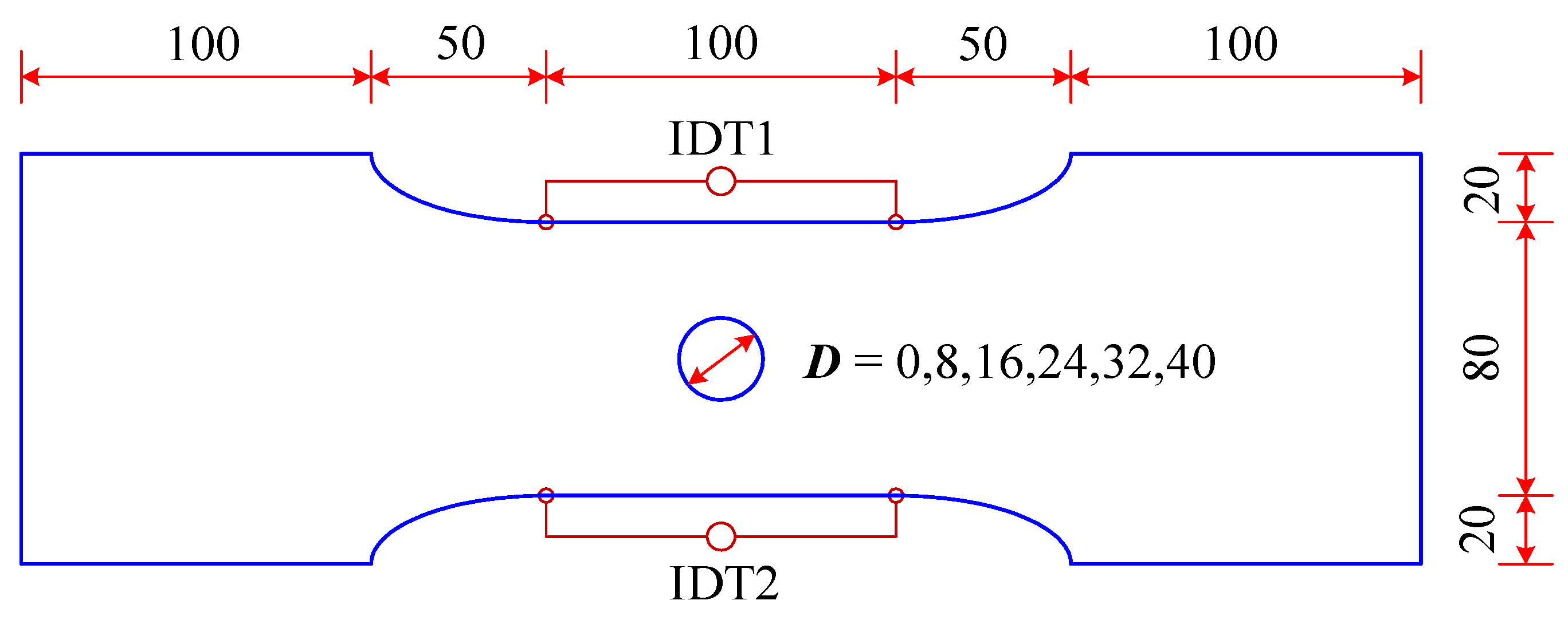
In project RUOSTE [25,26], experimental results on S700MC and S960Q plates with and without hole under tensile loading were conducted and reported. In this paper, these experimental results will be revisited to discuss the material plastic and ductile fracture behaviors of these two HS steels. The dimensions of the steel plate without hole and center-holed (CH) tension specimens are shown in Figure 1. The specimen gripping length in the tensile loading tests was 100 mm. All specimens had a thickness of 8 mm. The displacement gauge length was equal to the specimen parallel length of 100 mm. The width of the gauge part was 80 mm. The CH specimens had a round hole in the plate center with five diameters from 8 mm up to 40 mm. In the tensile loading, apart from recording the loading force, relative displacements in the gauge length were measured using inductive displacement transducers (IDT) on both sides of specimens to obtain the elongations during tensile tests, as illustrated in Figure 1.
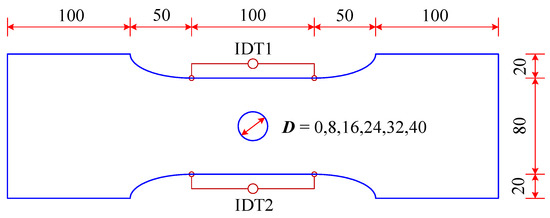
Figure 1.
Plate and center-holed tension specimens (unit: mm; according to [26]).
When the tensile specimens begin to neck in the tensile tests, the true stress and strain in the necking region will be uneven distribution. The only monitored force in tensile coupon tests is the total tensile force and the engineering stress can then be obtained. Although the minimum area in the necking region can also be monitored, due to the uneven longitudinal stress distribution, the true stress in the necking region cannot be calculated. Consequently, the true stress corresponding to true strain in the necking region is difficult to be directly measured. For tensile coupon tests, the load–displacement curves are generally monitored, based on which the engineering stress–strain curves of the tested steel material can then be obtained.
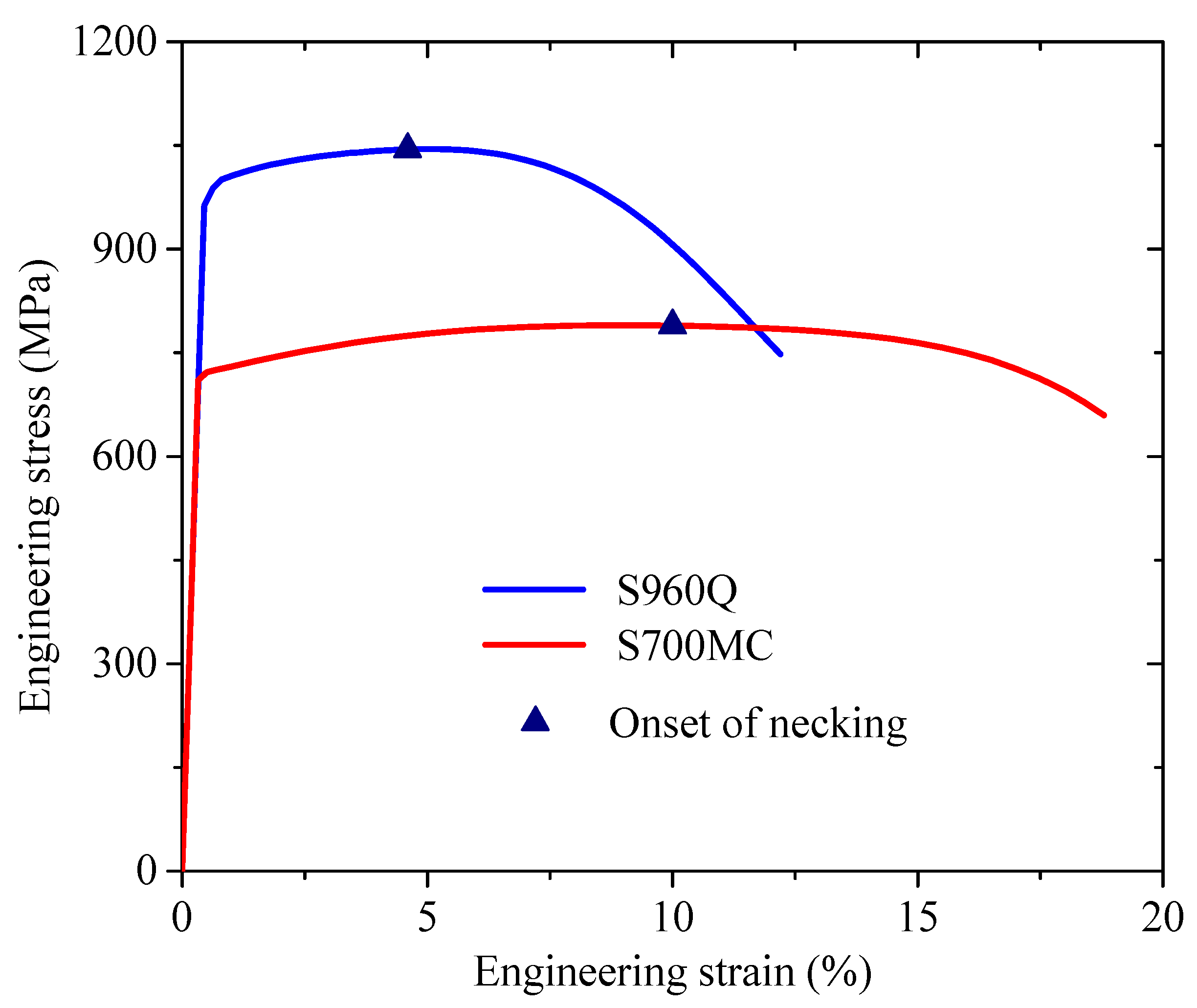
Figure 2 shows the measured full-range engineering stress–strain curves for S700MC and S960Q from tensile coupon tests on plate specimen without hole [26]. The ductility of S700MC is superior to S960Q, since the engineering strains corresponding to tensile strength and fracture for S700MC are larger than S960Q, as listed in Table 1. Besides, a larger decreasing ratio for S960Q engineering stress after the onset of necking can be seen compared to that of S700MC. This indicates the strain-softening effect for S960Q is more significant than S700MC. Table 1 lists the major material properties based on the tensile coupon experimental results of plate specimens. These properties will be used in the following FE simulations.
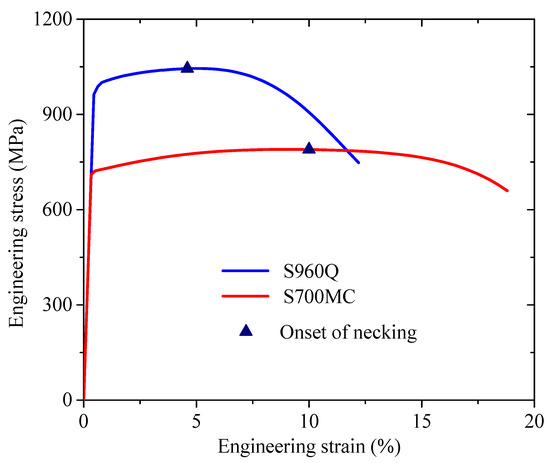
Figure 2.
Engineering stress–strain curves of S700MC and S960Q (according to [26]).

Table 1.
Material properties from S700MC and S960Q plate tension tests (according to [26]).
S700MC is manufactured by a thermo-mechanically controlled process (TMCP) and this process would produce more ductile steel material. In the cold-forming process of steel components, steel material would undergo large deformation and insufficient ductility of steel material will lead to tearing of steel in the cold-forming. Therefore, the better ductility of S700MC benefits its application in fabricating cold-formed steel components, which are popularly used in various steel structures.
2.2. Full-Range True Stress–Strain Relations
Given that the measurement of true stress is not possible to be realized, a calibration method can be considered to obtain the true stress through conducting combined experimental test and numerical analysis. In the finite element simulation of tensile tests, a true stress–strain relationship can be assumed first, and the output engineering stress–strain curve from the finite element simulation can be made comparisons with the measured results. If the engineering stress–strain curve from the finite element analysis is close to the experimental results, it can be deemed that the used true stress–strain relationship in the finite element analysis is close to the actual value of the material.
Conventional stress–strain models are to describe the initial stage of steel strain-hardening effect. Hertelé et al. [27] made a complete review of the existing stress–strain models, including those of Ludwik, Ramberg-Osgood, Hollomon, Voce, Swift, and Ludwigson. These models are power or exponential expressions or their combinations. Hertelé et al. [27] also proposed a generic stress–strain model with two-stage strain-hardening behavior, allowing a more accurate description of the pre-necking stress–strain relation. In practice, the pre-necking true stress–strain relation can be obtained by using Equations (1) and (2), in which σt and εt denote true stress and strain, while σe and εe are the engineering stress and strain from tensile coupon tests. In this study, the numerical pre-necking stress–strain relations for S700MC and S960Q were considered in the FE analysis, which were directly converted from the tensile coupon experimental results by using Equations (1) and (2).
Accurately considering the post-necking true stress–strain relation is necessary for conducting FE simulation for steel structures, especially undergoing large deformation or predicting the fracture behavior. However, the post-necking stress–strain behavior cannot be directly inferred from the descending stage of engineering stress–strain curves. Recently, a combined Swift-Voce stress–strain law was widely used to describe steel full-range stress–strain relation, which is a combined power and exponential expression with six parameters and a weighting factor [28,29,30]. Ling [31] proposed a combined linear and power stress–strain law only to describe the post-necking stress–strain, as shown in Equation (3). This law was adopted in this paper to calibrate the post-necking true stress–strain relation of S700MC and S960Q due to its simplicity. In this law, the linear law describes a linear post-necking stress–strain relation as expressed in Equation (4), while the power law uses Hollomon’s power stress–strain relation as expressed by Equation (5) [32].
The stress continuity condition at the onset of necking of Equation (6) and the initial necking condition of Equation (7) need to be satisfied simultaneously both for linear law of Equation (4) and power law of Equation (5).
In which σt,u and εt,u denote the true stress and strain at the onset of necking, respectively. Parameters in power and linear laws can be obtained: , , , and . Values of true stress σt,u and strain εt,u at the onset of necking can be calculated according to Equations (1) and (2), based on the corresponding engineering stress σe and strain εe as marked in Figure 1. Then, parameter values in combined linear and power law of Equation (3) can be obtained except for the weighting factor W. Table 2 lists the true stress σt,u and strain εt,u at the onset of necking for S700MC and S960Q, respectively, and the parameter values in the combined linear and power law for the following analysis.

Table 2.
Parameters for post-necking true stress–strain relations.
Ling [31] considered the linear law of Equation (4) and the power law of Equation (5) were the upper and lower bounds for the post-necking true stress–strain relation of alloy materials, respectively. Therefore, the range of validity for the weighting factor W in Equation (3) was defined in the range between 0 and 1. However, in the recent study on the post-necking true stress of high-strength steels, it was found that using the power low of Equation (5) would overestimate the post-necking stress [33,34]. Therefore, the power law should not be subjectively considered as the lower bound to describe the post-necking true stress. In this paper, the Ling method was still adopted to describe the post-necking true stress, but it was deemed that the parameter W can be set to be less than 0, as the stress continuity condition at the onset of necking of Equation (6) and the initial necking condition of Equation (7) were still satisfied when a negative W value was used. Accordingly, the Ling method was extended in this paper. Equation (3) proposed by Ling [31] can be regarded as a mathematic expression and the parameter W can be set as any real number.
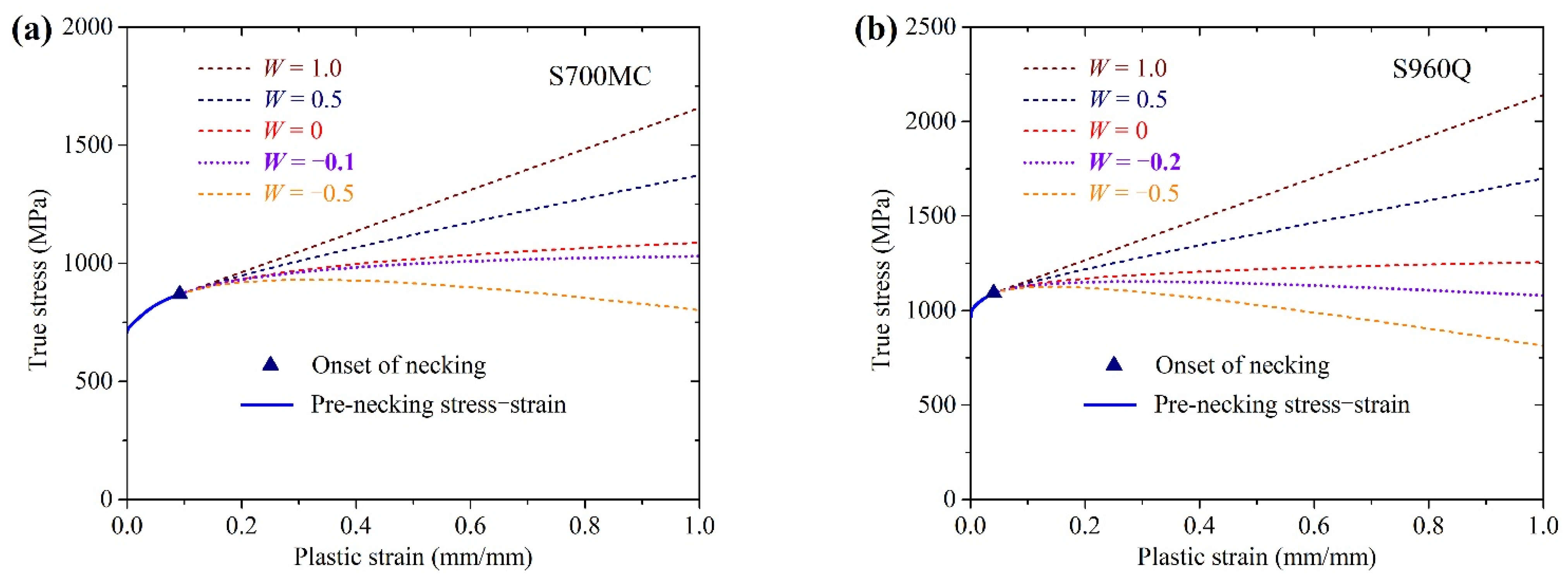
Figure 3 shows the full-range true stress-plastic strain curves of S700MC and S960Q, in which the pre-necking portion was converted from measured engineering stress–strain relation using Equations (1) and (2), and the post-necking portion was based on Equation (3) with various values for weighting for W. The combined linear and power law generated very smooth post-necking stress–strain curves following the pre-necking ones. The lower bound exponential law with weighting factor W = 0 yielded a slowly increasing post-necking stress–strain curve for both HS steels. In this paper, the combined linear and power law was used to describe the post-necking stress–strain relations of S700MC and S960Q, in which the material damage was incorporated in the plastic behavior.
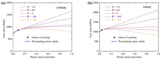
Figure 3.
Full-range true stress–strain curves: (a) S700MC and (b) S960Q.
2.3. FE Analysis on Plate Specimens
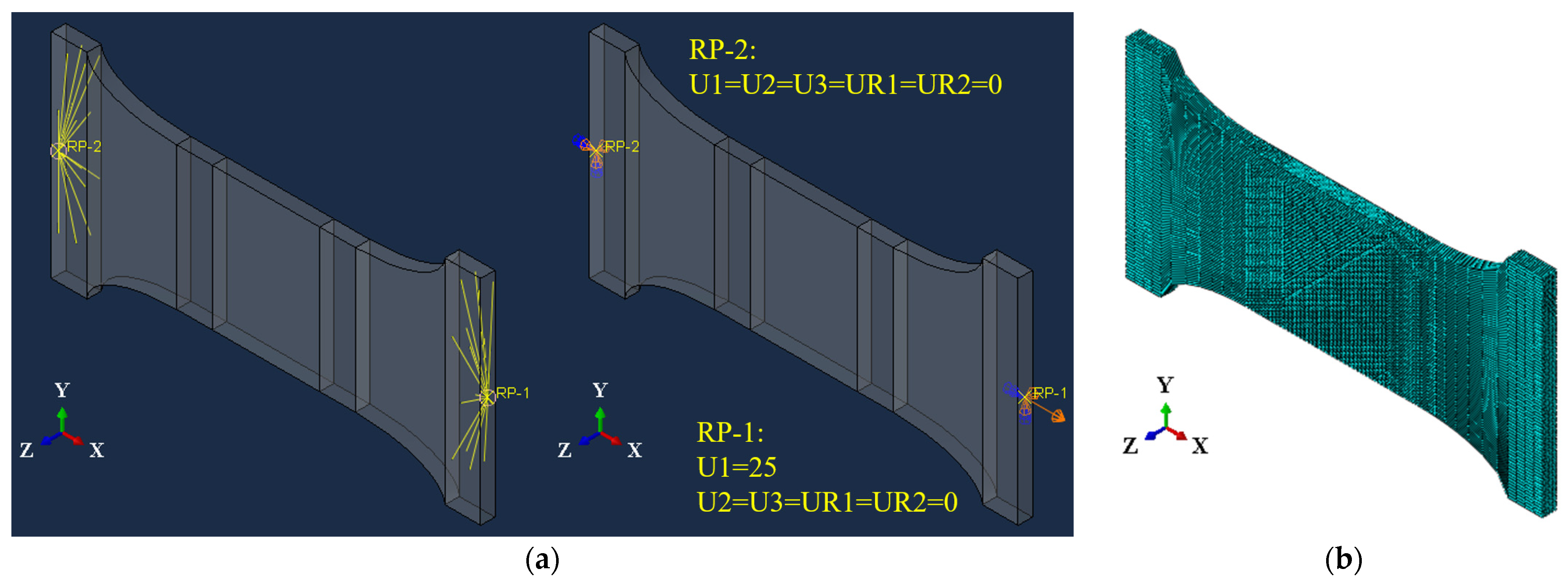
Tensile experiments on plate specimens were modelled using an FE analysis software ABAQUS (version 6.13, Dassault Systèmes Simulia Corp., Providence, RI, USA) [35], as shown in Figure 4. The plate longitudinal length in clamped part of FE model was only 1/5 of that in actual tests to improve the FE analysis efficiency. As shown in Figure 4a, the left and right clamping surfaces were coupled to a reference point at the respective end by all six freedoms. The freedoms of the left reference point RP-2 were fully constrained except for the rotation around Z-axis, that is U1 = U2 = U3 = UR1 = UR2 = 0. Axial displacement was applied to the X-direction of the right reference point RP-1 to simulate the tensile loading, and other freedoms were constrained except for the rotation around Z-axis, that is U1 = 25, U2 = U3 = UR1 = UR2 = 0 for S700MC. The rotation around Z-axis for left and right reference points was free since tensile coupons could slightly rotate around Z-axis due to the much weaker constraint in this direction. Mises yield criterion was used to describe the yield surface with the associated plastic flow. Quasi-static analyses on tensile plate specimens were carried out using the explicit solver in ABAQUS. Eight node hexahedral solid elements with reduced integration (C3D8R) were adopted to simulate the elastic and plastic behavior of plate specimens, as shown in Figure 4b. The target time increment was set to 0.001 s and the duration of the tensile step in simulations was 200 s. The engineering stress–strain curves from FE simulation results were obtained by postprocessing the elongated gauge length and the force in tension at each time step.
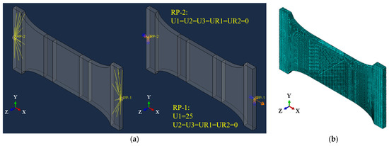
Figure 4.
FE model and mesh for plate specimens: (a) FE model and (b) FE mesh.
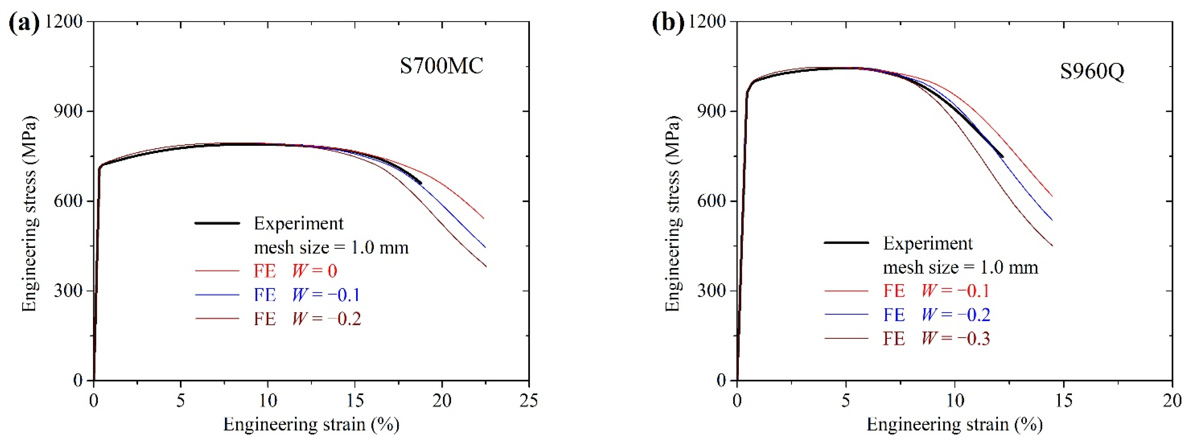
Equation (3) was used to describe the post-necking stress–strain relations of S700MC and S960Q. A suitable weighting factor W for each steel can be calibrated through comparing the descending stage of the FE simulated engineering stress–strain curves and the experimental ones. Figure 5 shows the comparison results for these two steels. As shown in Figure 5a, using W = 0 to describe the post-necking stress–strain behavior of S700MC, it would produce a higher prediction for the descending part of the engineering curve, while using W = −0.2 would result in a lower prediction. As shown in Figure 5b, using W = −0.1 and W = −0.3 to describe the post-necking stress–strain behavior of S960Q, the results would be overestimated or underestimated, respectively. After many calculations and comparisons, it was concluded that weighting factors W = −0.1 and W = −0.2 were suitable to describe the post-necking stress–strain relations of S700MC and S960Q, respectively. The calibrated post-necking stress–strain relations of S700MC and S960Q can be seen in Figure 3 with W = −0.1 and W = −0.2, respectively. The post-necking true stress–strain curve for S700MC had a slightly increasing trend, whereas the post-necking curve for S960Q gradually decreased when plastic strain increased in size.
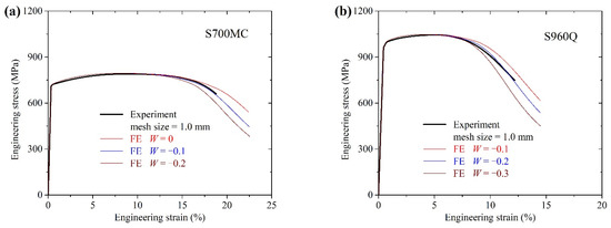
Figure 5.
Calibration for the weighting factor W: (a) S700MC and (b) S960Q.
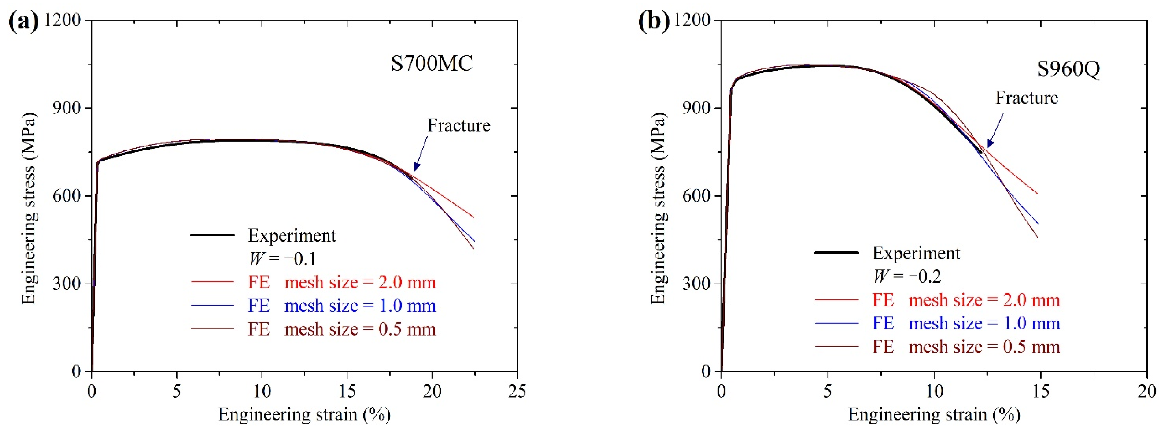
Mesh size in plate parallel parts may affect the FE simulation results since the strain localization effects in FE analysis were mesh-dependent. Cubic elements with mesh size 2.0 mm, 1.0 mm, and 0.5 mm were used in the plate parallel parts. Figure 6 shows the comparisons of the FE simulation and experimental engineering stress–strain curves for S700MC and S960Q plates with these three mesh sizes. Using mesh size 2.0 mm in parallel parts resulted in slightly larger engineering stress for S700MC and S960Q plates when plates were close to the fracture. For the simulation of S700MC with W = −0.1, FE results with mesh sizes 1.0 mm and 0.5 mm agreed well with the experimental one. For S960Q with W = −0.2, FE results with mesh size 1.0 mm agreed well with the experimental one, while mesh size 0.5 mm lead to larger engineering stress in the descending stage. Therefore, the FE simulation with mesh size equal to 1.0 mm in parallel parts of S700MC and S960Q plates were adopted in the following analysis.
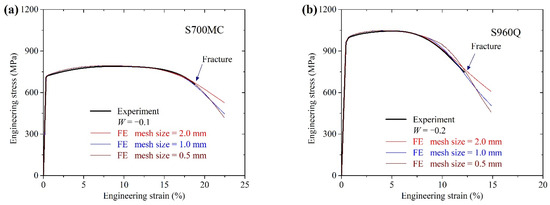
Figure 6.
Mesh size effect on the FE engineering stress–strain curves: (a) S700MC and (b) S960Q.
3. Ductile Fracture Criterion
3.1. Uncoupled Ductile Fracture
The application of combined linear and power stress–strain law of Equation (3) with a suitable weighting factor in FE analysis could yield accurate descending engineering stress–strain curves for plate specimens. Therefore, the calibrated post-necking stress–strain relation for S700MC and S960Q could be used to describe their degraded post-necking plastic behavior approximately. On this basis, the uncoupled ductile fracture criterion will be considered separately to predict the initial fracture.
The ductile fracture criterion was a phenomenological model for predicting the onset of fracture under monotonic loading. In the last few decades, the void growth model (VGM) was developed to predict the ductile fracture of materials based on the relation between the growth rate of voids and stress triaxiality [36,37,38,39], which is an exponential function found by Rice and Tracey through analyzing a spherical void in a simple tension strain rate field [40]. In the VGM, material fracture was predicted to occur when the void growth index (VGI) reached a critical value. This corresponds to the voids growing large enough to trigger necking instabilities between voids resulting in coalescence and macrocrack formation [36,37,38,39].
Džugan et al. [17] reported the identification of ductile damage parameters for two typical reactor pressure vessel steels. The ferritic steel is used for vessels and the austenitic steel for internals due to its better ductility. It was observed that the fracture locus for the ferritic steel exhibited dependence only on stress triaxiality, while the Lode angle also affected the fracture locus of the austenitic steel apart from stress triaxiality. Ductile fracture criteria with exponential expressions, such as the Rice–Tracey model and the Johnson-–Cook model, were calibrated for steels.
The ductile fracture criterion was defined as a function between fracture equivalent plastic strain and stress triaxiality , which is an exponential expression as Equation (8) found by Rice and Tracey [40]. Parameter β was taken as −1.5 according to curve fitting results based on the experimental investigations by Džugan et al. [17]. The only unknown α was the fracture parameter that can be calibrated for each steel. In Equation (8), is the stress triaxiality, is the pressure stress, is the Mises equivalent stress, and , can be expressed as the principal stress , , . Equation (9) shows the relationships of stress triaxiality to the principal stresses.
The ductile fracture will occur when the condition of Equation (10) is satisfied, in which is the equivalent plastic strain (PEEQ), is the fracture equivalent plastic strain as expressed in Equation (8), is the fracture variable that increases monotonically with plastic deformation in the uncoupled damage model. At each increment during the analysis, the incremental increase in is computed as expressed in Equation (11). In Equation (11), is the incremental increase in equivalent plastic strain for any element in the finite element model. The corresponding stress triaxiality for any element in the finite element model can also be calculated. Actually, is a function of the element stress triaxiality . Then, for any element can be calculated by the ratio of to the fracture equivalent plastic strain . When the accumulation of the for any element in the loading process reaches 1.0, the fracture initiation would occur for this element. Equations (10) and (11) can be seen in ABAQUS analysis user’s guide [35].
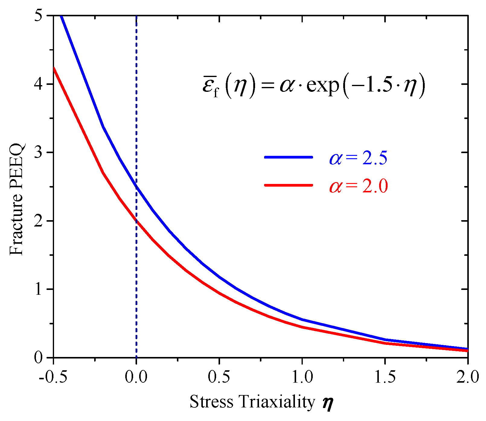
Figure 7 shows the relation between fracture PEEQ and stress triaxiality η with two fracture parameters α = 2.0 and α = 2.5. With the increase in stress triaxiality η, fracture PEEQ had a deceasing trend, and the variation of the fracture parameter α had less of an effect on fracture PEEQ. The fracture criterion of Equation (8) with fracture parameters α = 2.0 and α = 2.5 will be checked in the following analysis to predict the tensile fracture of plate specimens.
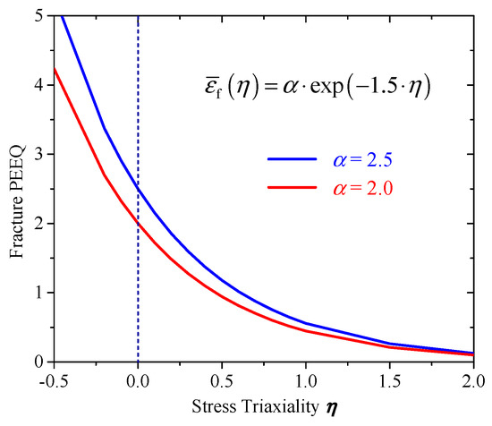
Figure 7.
Relation between fracture PEEQ and stress triaxiality.
3.2. Tensile Fracture of Plate Specimens
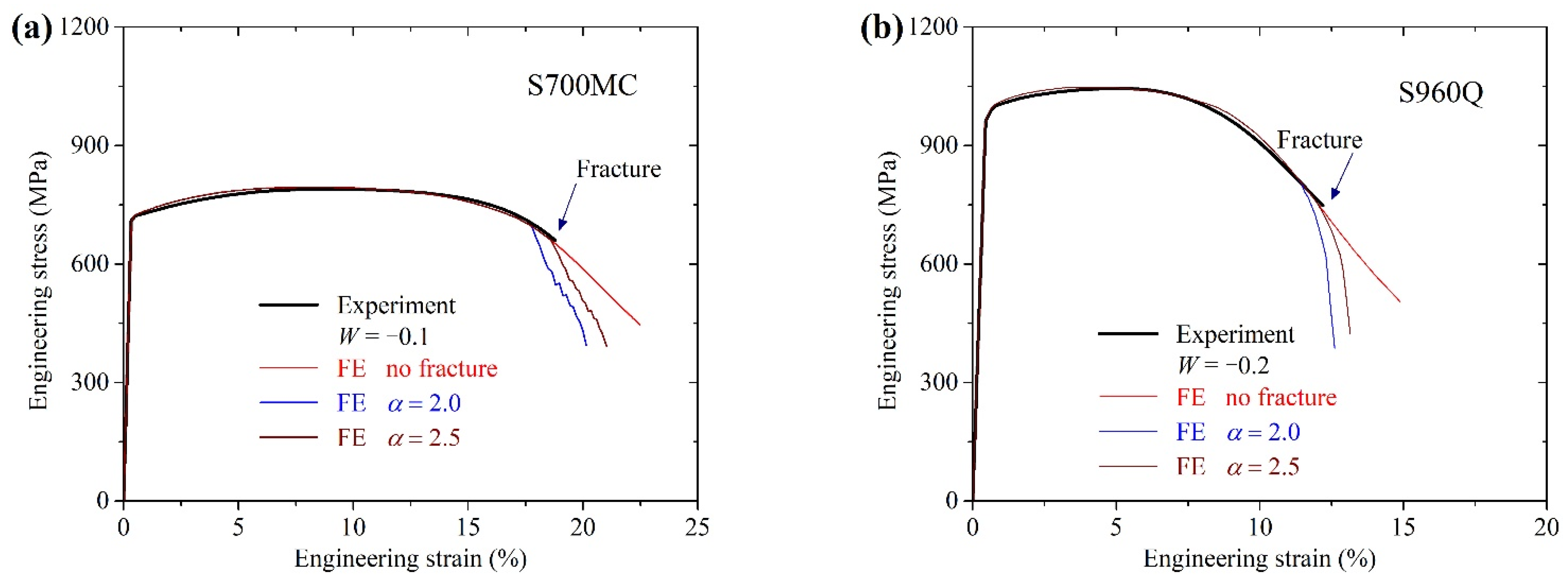
The tensile experiments on S700MC and S960Q plate specimens reported in [26] were modelled using the calibrate plastic behavior and the ductile fracture criterion. In the ductile fracture criterion, the fracture parameter α was set to 2.0 and 2.5 for both steels. Figure 8 shows the comparisons between the FE-analyzed engineering stress–strain curves and the experimental results for two steels. Considering the calibrated plastic behavior in the FE analysis generated almost the same descending engineering stress–strain curves to the corresponding experimental results. For S700MC calculations, the fracture model with α = 2.5 generated almost the same fracture engineering strain as experimental value. For S960Q calculations, the fracture engineering strains in FE results with fracture parameter α = 2.5 were close to the corresponding experimental value.
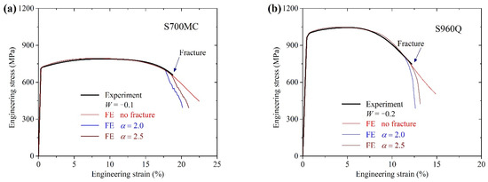
Figure 8.
Comparisons between FE and experimental engineering stress–strain curves: (a) S700MC and (b) S960Q.
4. Modelling of CH Specimens
4.1. Force-Displacement Curves
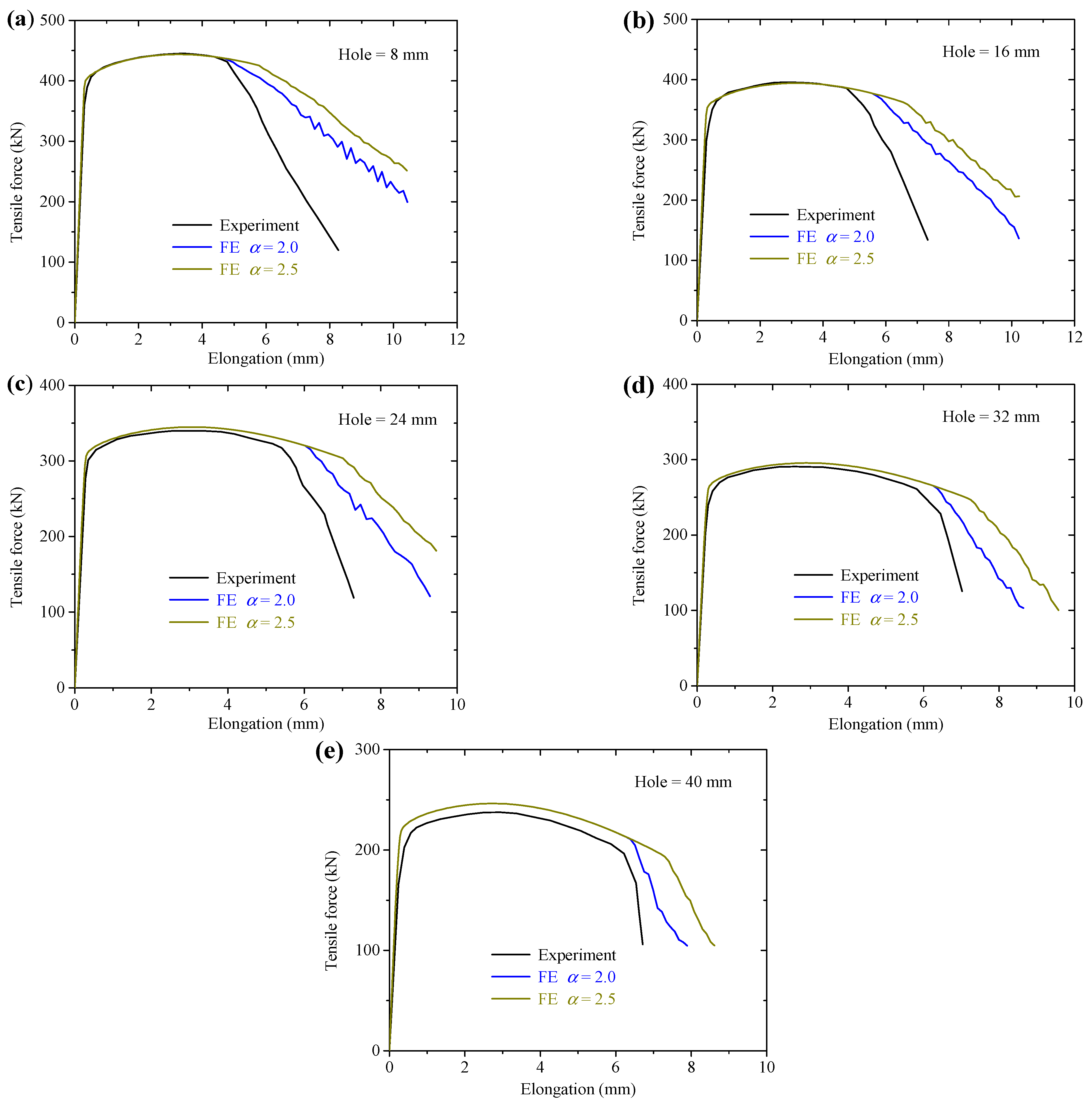
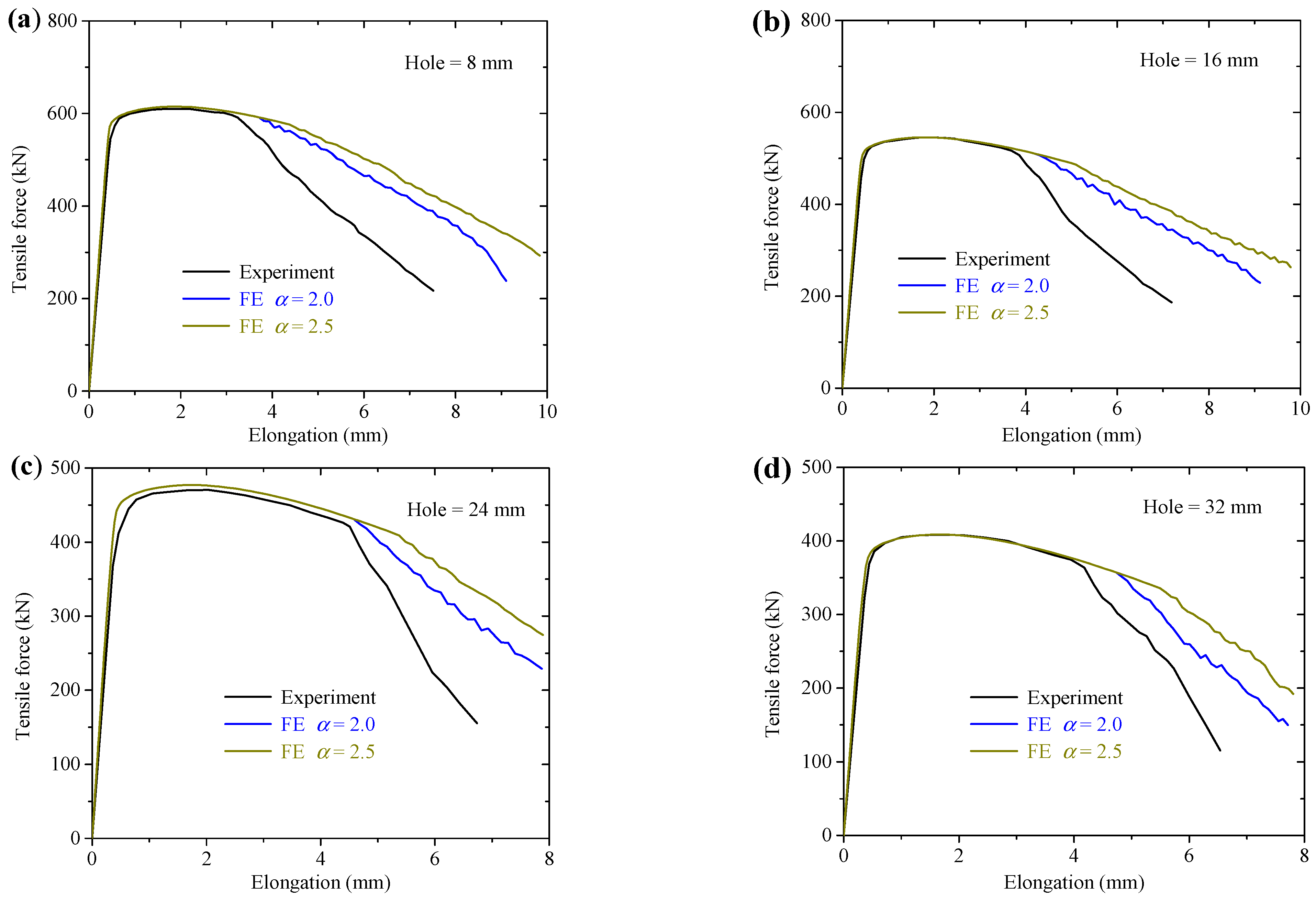
S700MC and S960Q center-holed (CH) tension experiments with hole diameter from 8 mm up to 40 mm, reported in [26], were revisited and modelled based on the ductile fracture models. In the fracture modelling of S700MC and S960Q CH specimens, two fracture parameters α = 2.0 and α = 2.5 were checked for each steel. These two types of FE simulation results including the damage properties were obtained and compared with the corresponding experimental results.
Figure 9 shows the FE force-displacement curves compared to the experimental results for S700MC CH specimens. Except for specimen with hole diameter 40 mm, the FE force-displacement curves for the other four specimens agreed well with the experimental results, including the whole increasing and descending stages until the initial fracture. The deviation for the specimen with a hole diameter of 40 mm between the FE analysis and the experimental force-displacement curves may result from the specimen geometry deviation, such as a thinner thickness used. The FE analysis results based on the ductile fracture model with parameter α = 2.5 resulted in a larger tensile elongation than using α = 2.0. It can be concluded that the fracture parameter α in the ductile fracture model governs the deformation capacity of the CH specimens.
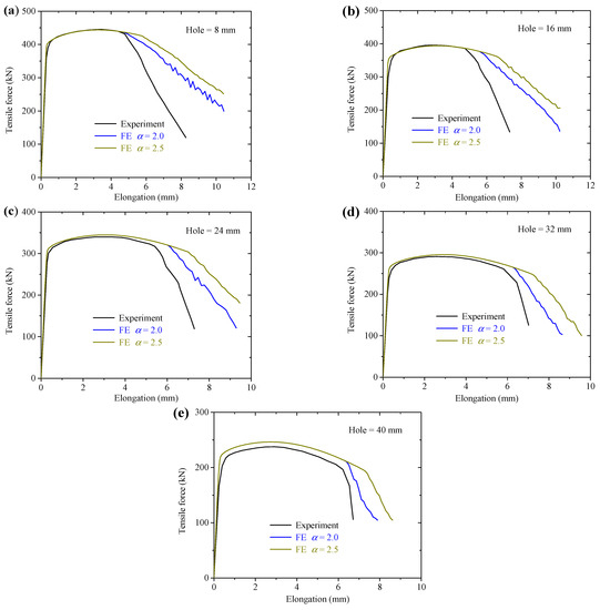
Figure 9.
Comparisons between FE and experimental tension-elongation curves for S700MC: (a) hole diameter = 8 mm; (b) hole diameter = 16 mm; (c) hole diameter = 24 mm; (d) hole diameter = 32 mm; (e) hole diameter = 40 mm.
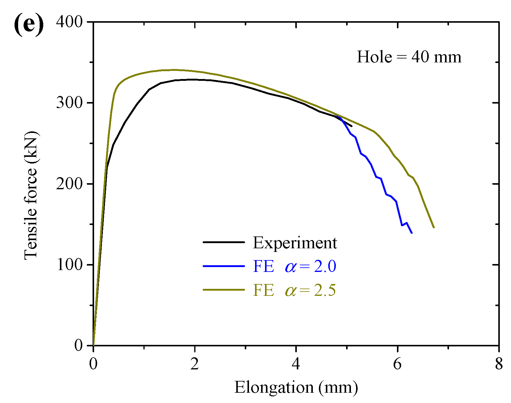
Figure 10 shows the FE analysis force-displacement curves for S960Q CH specimens compared to the corresponding experimental results. Similar to the S700MC FE analysis results, the fracture parameter α = 2.5 resulted in a larger deformation capacity for the CH specimens than using α = 2.0 in the ductile fracture modelling. The FE force-displacement curves for S960Q CH specimens agreed well with the experimental results until the initial fractures. For the CH specimen with a hole diameter of 40 mm, see Figure 10e, there were some differences between the numerical force-displacement curves and the corresponding experimental results. The numerical force-displacement curve of this specimen had the same increasing and decreasing trend compared to other CH specimens. However, the experimental force-displacement curve of this specimen in the increasing stage had a different increasing trend compared to other CH specimens. Accordingly, it was considered that there may be some experimental errors in the load-increasing stage for the CH specimen with a hole of 40 mm, resulting in the difference between the FE and experimental curves. Moreover, the experimental errors for the specimen only affect the plastic behavior and the experimental fracture behavior can still be compared with the corresponding FE prediction result. Note that the ductile fracture models calibrated in this paper were to simulate the initial fracture of the material properties. After the initial fracture of the CH specimens, the crack propagation behavior cannot be predicted accurately based on the adopted ductile fracture models.
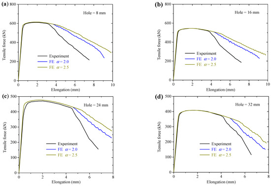
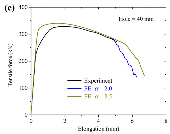
Figure 10.
Comparisons between FE and experimental tension-elongation curves for S960Q: (a) hole diameter = 8 mm; (b) hole diameter = 16 mm; (c) hole diameter = 24 mm; (d) hole diameter = 32 mm; (e) hole diameter = 40 mm.
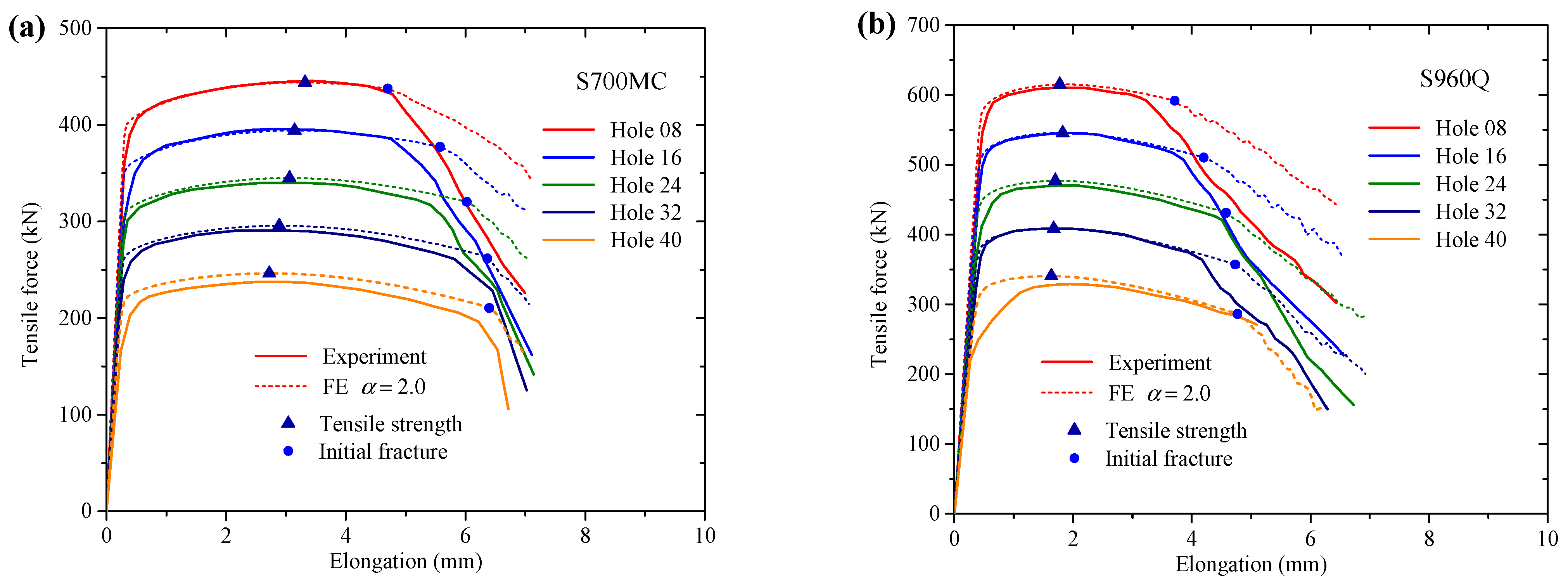
Figure 11 shows the tensile force vs. elongation curves for five groups of CH specimens. It can be seen for S700MC and S960Q specimens, the FE simulation results would accurately predict the plastic behaviors, especially for the increasing part. Therefore, the calibrated plasticity for HS steels was effective for predicting the tensile strength of CH specimens. In addition, the descending parts in the force-displacement curves were almost close to the experimental results for most specimens. For the initial fracture of the CH specimens, it can be concluded that using the ductile fracture criterion of Equation (8) with α = 2.0 would produce close predictions for the fracture deformation both for S700MC and S960Q specimens. It indicates the ductile fracture criterion of Equation (8) should be calibrated in detail for more accurate fracture prediction.
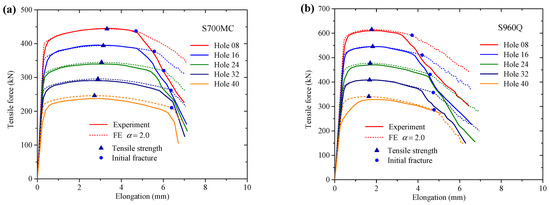
Figure 11.
Results of ductile fracture modelling for CH specimens: (a) S700MC and (b) S960.
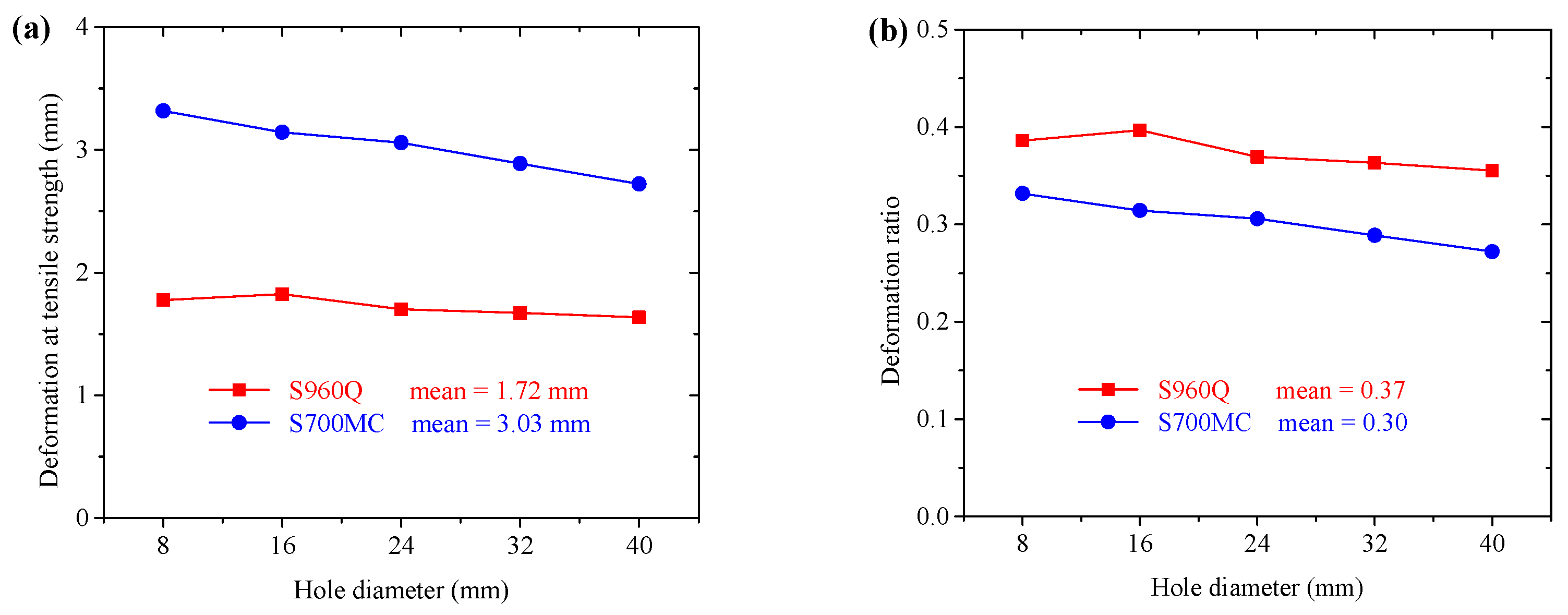
The elongations of the CH specimens corresponding to the tensile strength were compared, as shown in Figure 12. With the increase in the hole diameter, the elongations at the tensile strength had a decreasing trend both for S700MC and S960Q. Due to the better ductility of S700MC, the decreasing trend was more significant. The average deformations at the tensile strength for S700MC and S960Q CH specimens were 3.03 mm and 1.72 mm, respectively, see Figure 12a. The larger material ductility produces larger deformation at the tensile strength for CH specimens.
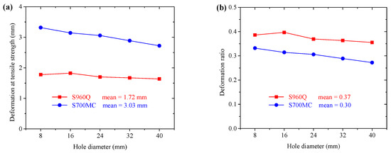
Figure 12.
Deformation distribution for CH specimens: (a) deformation at tensile strength (b) deformation ratio.
For studying the effect of the hole on the deformation capacity of the tensile specimen, the deformations at the tensile strength for CH specimens were compared to that of plate specimens for two steels. The deformations at the tensile strength for plate specimen of S700MC and S960Q were 10 mm and 4.6 mm, respectively, which was calculated according to the strain at the tensile strength and the gauge length. Figure 12b shows the comparison results between the deformation capacity of CH specimens and the corresponding plate specimens. With the increase in the hole diameter, the ratios had a decreasing trend for both steels. The average ratios for S700MC and S960Q were 0.30 and 0.37, respectively. The lesser material ductility resulted in a higher average ratio. It can be concluded that the hole in the specimen would significantly reduce the deformation capacity of the tensile plate specimens.
4.2. Fracture Modes
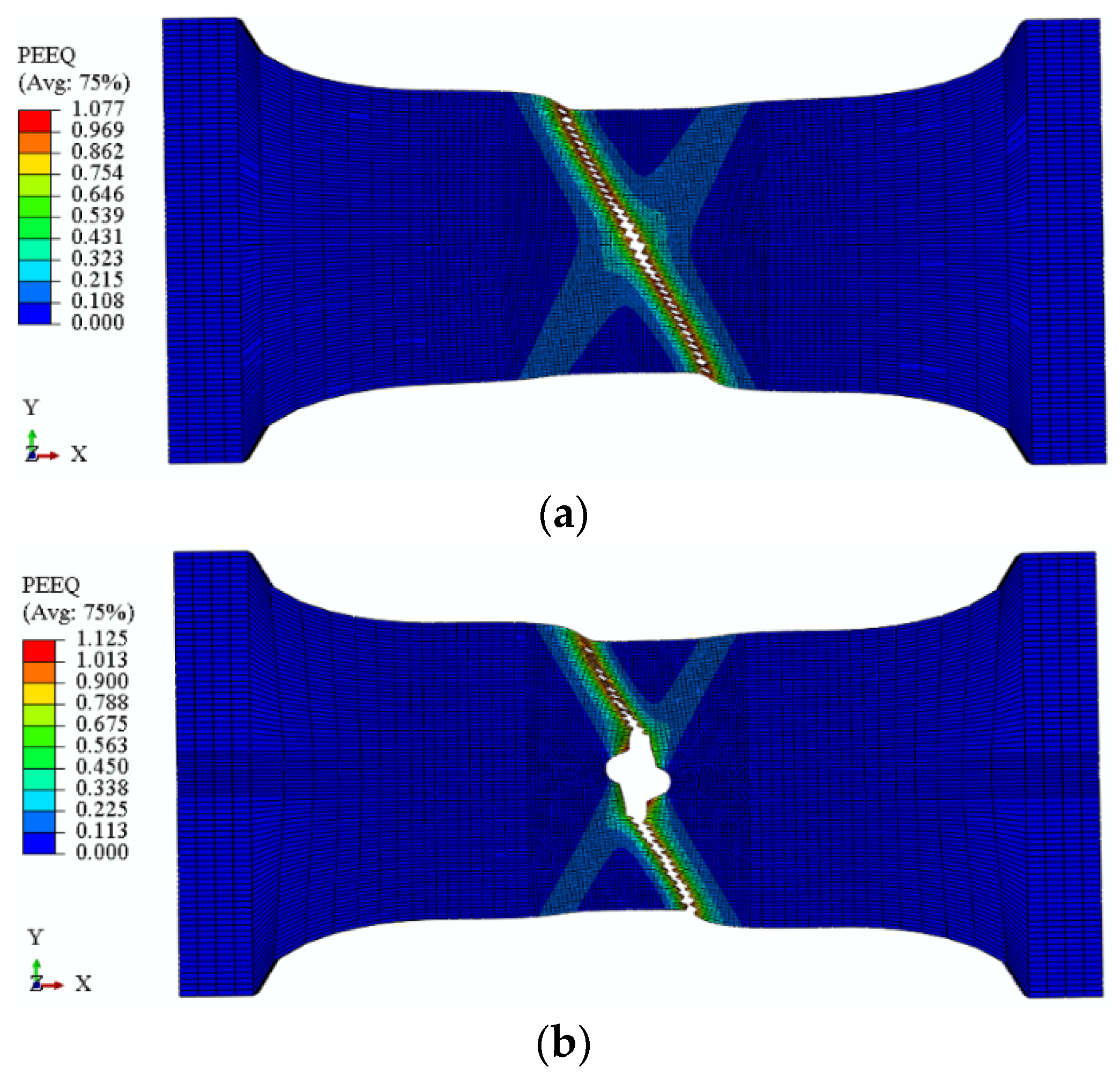
Figure 13 shows the FE analysis and experimental failure modes of S960Q plate and CH specimen with an 8 mm hole. The FE analysis initial fracture locations both in plate and CH specimens were consistent with the experimental results [26]. This indicates that the FE analysis incorporating the proposed plastic and fracture models estimated the net cross-section failure modes very well. The FE analysis descending load–displacement curves after the initial fracture for the CH specimens were overestimated significantly compared to the corresponding experimental results, see Figure 9, Figure 10 and Figure 11. This was because the proposed fracture models cannot estimate the fracture evolution process, which may also be governed by the material shear fracture behavior. Nevertheless, the final fracture models can still be predicted the same as the experimental ones.
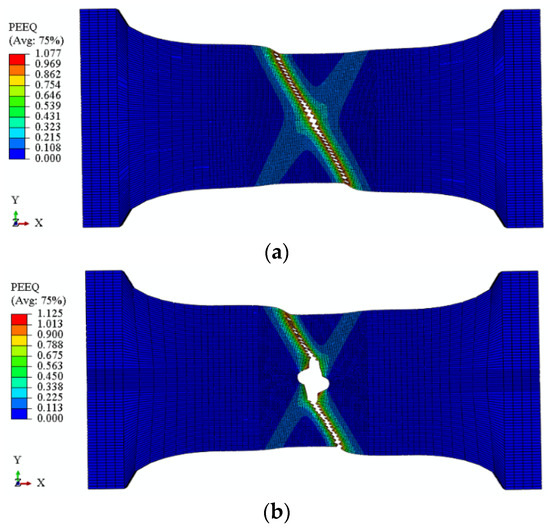
Figure 13.
FE and experimental failure modes of S960Q specimens: (a) FE failure mode of S960Q tension specimen without hole; (b) FE failure mode of S960 CH specimen with 8 mm hole.
4.3. Plastic Strain Distribution Close to Fracture
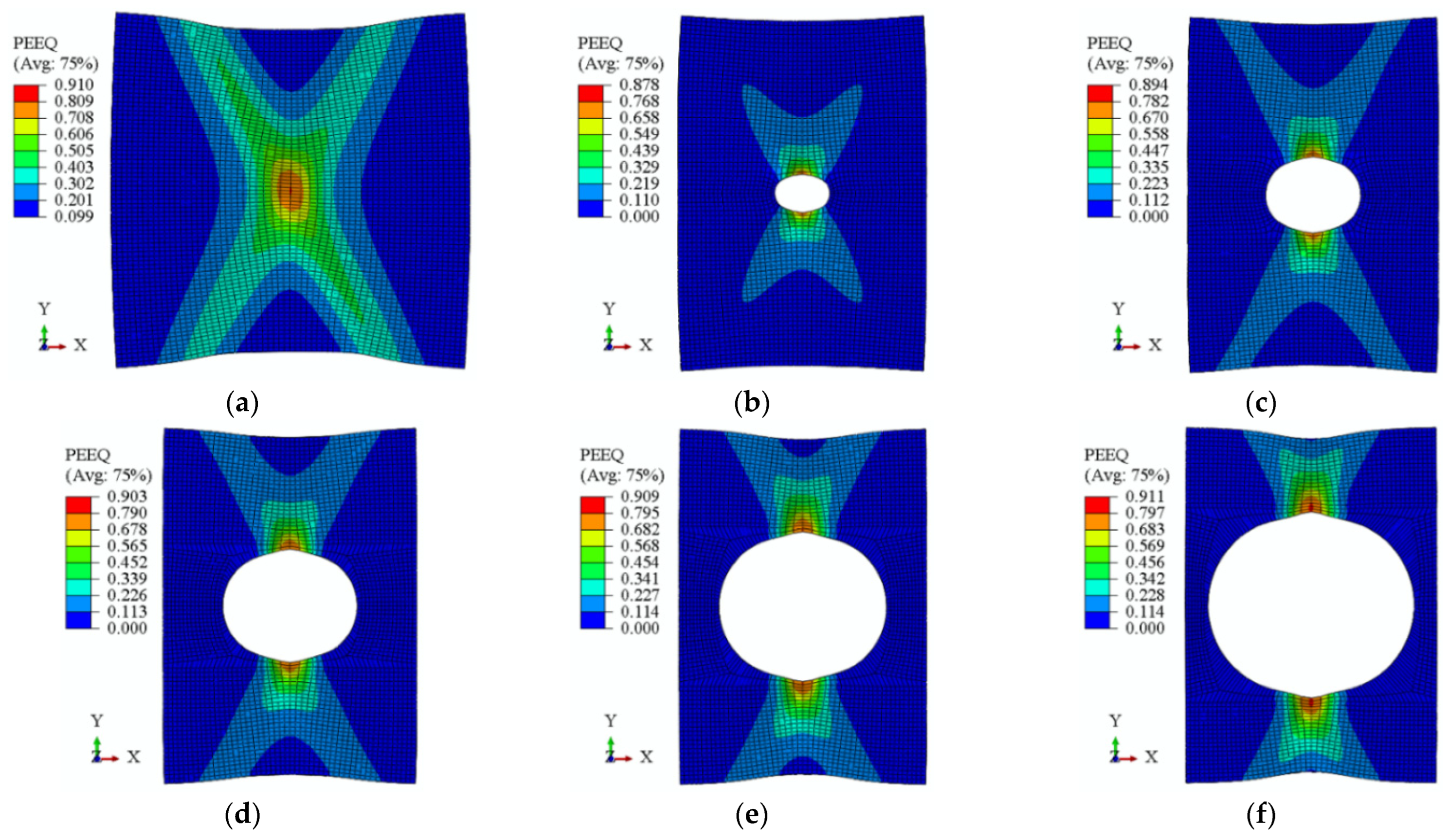
In addition to the load–displacement curves and final failure models, the deformation and stress and strain distributions could also be evaluated based on the calibrated plastic and fracture models. Figure 14 and Figure 15 show the equivalent plastic strain (PEEQ) distributions for the S700MC and S960Q plates and CH specimens with corresponding deformations at the initial fracture state, according to the ductile fracture modelling results. It can be seen from Figure 14 that the maximum PEEQs for S700MC specimens were about 0.9 and the 32 mm and 40 mm CH specimens were almost identical with values about 0.91. With the decrease in hole diameter in the CH specimens, the maximum PEEQs at the initial fracture state had a slightly decreasing trend. For S700MC CH specimen with an 8 mm hole, its maximum PEEQ was about 0.88 at the initial fracture state, and only a partial region around the hole rather than the entire net cross-section entered the plastic state.
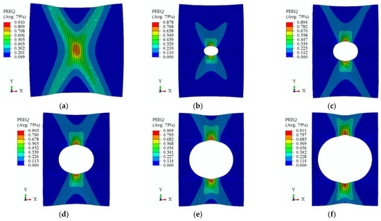
Figure 14.
PEEQ distribution of S700MC specimens at initial fracture. (a) plate; (b) hole = 8 mm; (c) hole = 16 mm; (d) hole = 24 mm; (e) hole = 32 mm; (f) hole = 40 mm.
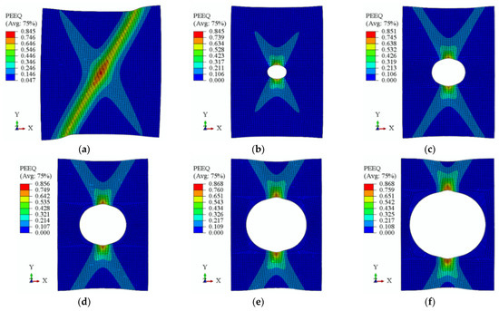
Figure 15.
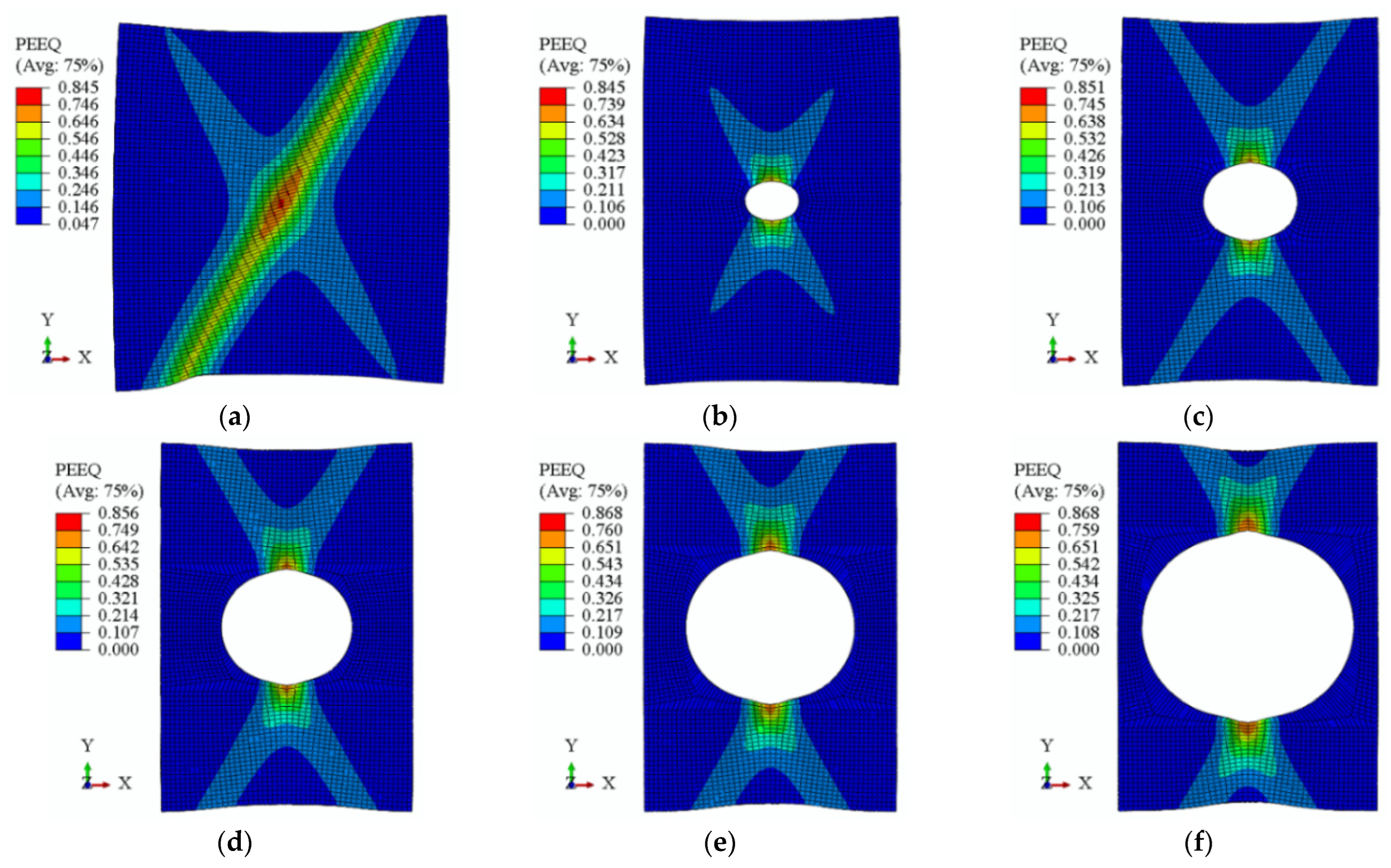
PEEQ distribution of S960Q specimens at initial fracture. (a) plate; (b) hole = 8 mm; (c) hole = 16 mm; (d) hole = 24 mm; (e) hole = 32 mm; (f) hole = 40 mm.
Figure 15 shows the PEEQ distributions of the S960Q plate and CH specimens at the initial fracture state. The maximum PEEQs of S960Q were about 0.85, a little smaller than that of S700MC. The necking regions for the S960Q plate at the initial fracture state had a major “I” shape instead of “X” shape for S700MC due to its higher tensile strength and lower ductility. For the S960Q CH specimens, the PEEQ distributions were similar to that for S700MC CH specimens at the initial fracture state.
4.4. Tensile Strength of Net Cross-Section
The net cross-section resistance Nu,Rd can be predicted by Equation (12) according to EN 1993-1-1 [41], in which Anet denotes the area of net cross-section, fu is steel tensile strength, and γM2 is partial safety factor equal to 1.25. Since the FE load–displacement curves agreed well with the experimental ones, the tensile strength based on the FE analysis was compared to the predictions by equation in the design specification of EN 1993-1-1.
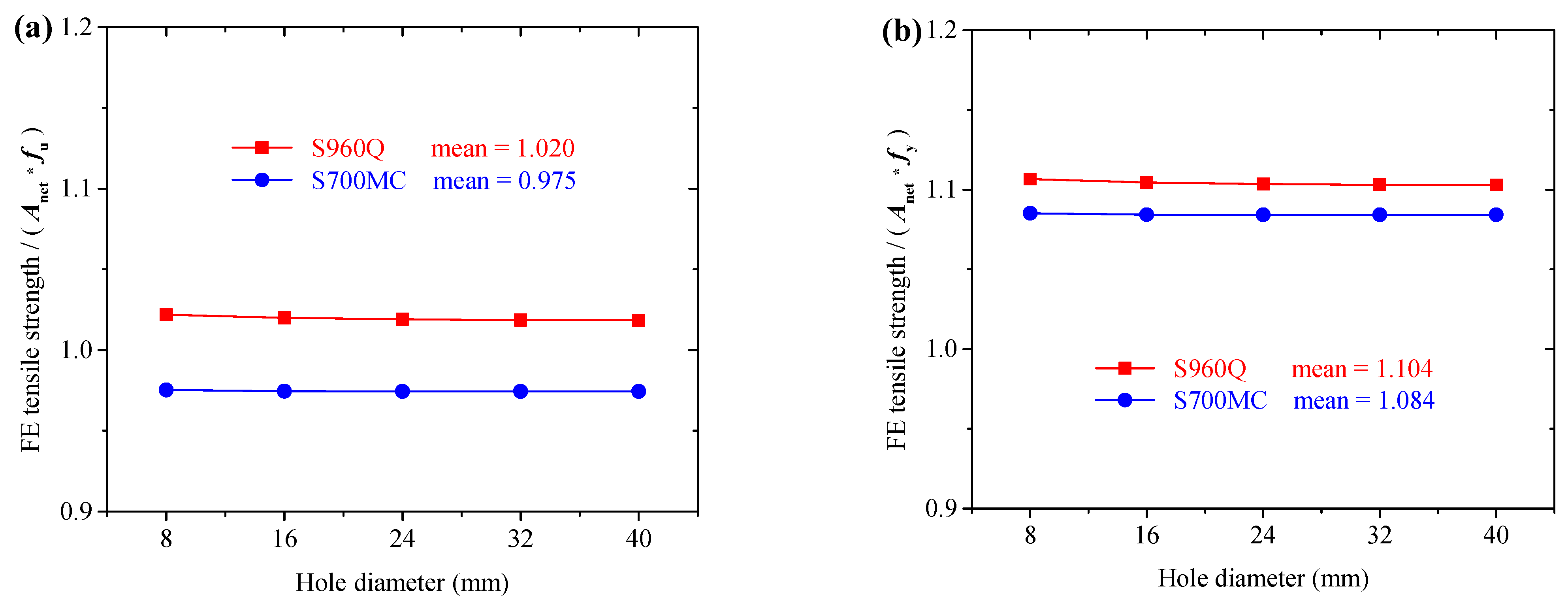
The tensile strengths corresponding to the ultimate tensile states in the FE analysis were compared to the net cross-section strength based on Equation (12) without factor 0.9 and partial factor γM2 = 1.25. Figure 16 shows the strength comparison results for the S700MC and S960Q CH specimens. The average ratios of the CH specimen FE analysis tensile strength to the corresponding equation prediction (Anet × fu) were 0.975 for S700MC and 1.02 for S960Q specimens with hole diameter from 8 mm to 40 mm, see Figure 16a. The effect of hole diameter on the ratios can be neglected. It can be concluded that the material ductility affected the tensile strength of net cross-sections, but the prediction equation in EN 1993-1-1, Equation (12), would result in rather conservative predictions. The FE analysis tensile strengths were also compared to the corresponding yield strength of the net cross-section (Anet × fu). Figure 16b shows the strength comparison results for the S700MC and S960Q CH specimens.
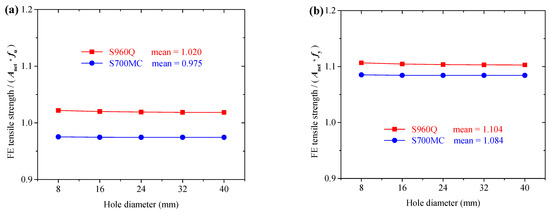
Figure 16.
Tensile strength comparisons: (a) compared to ultimate strength; (b) compared to yield strength.
As shown in Figure 16b, the average ratios of the CH specimen FE analysis tensile strength to the corresponding equation prediction (Anet × fu) were 1.084 for S700MC and 1.104 for S960Q specimens with hole diameter from 8 mm to 40 mm. All the ratios were larger than 1.0, proving that the net cross-section can be considered as whole yielding in the ultimate tensile state and the cross-sectional yielding strength can be regarded as the lower bond for the tensile strength.
5. Conclusions
This paper focused on the plasticity and ductile fracture of S700MC and S960Q center-holed plates under tension. A combined linear and power stress–strain law was used to describe the post-necking stress–strain relations, based on which an uncoupled ductile fracture criterion was calibrated. The plate and center-holed tensile specimens were modelled using the calibrated plastic and fracture models. The FE analysis load–displacements and failure models were compared to the available experimental results. The following conclusions can be drawn from the analysis.
- (1)
- The combined linear and power stress–strain law can be used to describe the post-necking stress–strain relations of S700MC and S960Q. The weighting factors in the combined law were calibrated to be −0.1 and −0.2 for S700MC and S960Q, respectively.
- (2)
- The uncoupled ductile fracture models were calibrated based on the Tracey–Rice damage criterion with the proposed post-necking degraded stress–strain relations. The fracture parameter was calibrated as 2.0 for S700MC and S960Q, proved by the good agreements of the FE analysis and experimental results of plate and CH specimens.
- (3)
- The fracture failure modes of plate and CH specimens were well predicted using the proposed fracture models. The maximum equivalent plastic strains around the bolt hole near the initial fracture were 0.90 and 0.85 for S700MC and S960Q, respectively.
- (4)
- The equation in EN 1993-1-1 gave conservative predictions for net cross-sectional tensile strength of the CH specimens.
Author Contributions
Conceptualization, Z.T. and F.Y.; methodology, F.Y.; software, S.W., Z.L. and A.C.; validation, Z.T. and S.W.; formal analysis, Z.T. and S.W.; investigation, S.W.; resources, F.Y.; data curation, Z.L. and A.C.; writing—original draft preparation, Z.T. and S.W.; writing—review and editing, Z.T., S.W., Z.L. and A.C.; visualization, F.Y.; supervision, F.Y.; project administration, F.Y.; funding acquisition, F.Y. All authors have read and agreed to the published version of the manuscript.
Funding
This research was supported by the Fundamental Research Funds for the Central Universities, CHD (No. 300102282102).
Data Availability Statement
The data presented in this study are available on request from the corresponding author.
Conflicts of Interest
The authors declare no conflict of interest.
References
- Jensen, L.; Bloomstine, M.L. Application of high strength steel in super long span modern suspension bridge design. In Proceedings of the Nordic Steel Construction Conference, Malmö, Sweden, 18–20 September 2009; pp. 494–501. [Google Scholar]
- Tran, A.T.; Veljkovic, M.; Rebelo, C.; da Silva, L.S. Resistance of cold-formed high strength steel circular and polygonal sections-Part 1: Experimental investigations. J. Constr. Steel Res. 2016, 120, 245–257. [Google Scholar] [CrossRef]
- Ban, H.Y.; Shi, G. A review of research on high-strength steel structures. Proc. Inst. Civ. Eng.-Struct. Build. 2017, 171, 625–641. [Google Scholar] [CrossRef]
- Može, P.; Beg, D.; Lopatič, J. Net cross-section design resistance and local ductility of elements made of high strength steel. J. Constr. Steel Res. 2007, 63, 1431–1441. [Google Scholar] [CrossRef]
- Može, P.; Beg, D. High strength steel tension splices with one or two bolts. J. Constr. Steel Res. 2010, 66, 1000–1010. [Google Scholar] [CrossRef]
- Može, P.; Beg, D. Investigation of high strength steel connections with several bolts in double shear. J. Constr. Steel Res. 2011, 67, 333–347. [Google Scholar] [CrossRef]
- Može, P. Bearing strength at bolt holes in connections with large end distance and bolt pitch. J. Constr. Steel Res. 2018, 147, 132–144. [Google Scholar] [CrossRef]
- Wang, Y.B.; Lyu, Y.F.; Li, G.Q.; Liew, J.Y.R. Behavior of single bolt bearing on high strength steel plate. J. Constr. Steel Res. 2017, 137, 19–30. [Google Scholar] [CrossRef]
- Wang, Y.B.; Lyu, Y.F.; Li, G.Q.; Liew, J.Y.R. Bearing-strength of high strength steel plates in two-bolt connections. J. Constr. Steel Res. 2019, 155, 205–218. [Google Scholar] [CrossRef]
- Lyu, Y.F.; Wang, Y.B.; Li, G.Q.; Jiang, J. Numerical analysis on the ultimate bearing resistance of single-bolt connection with high strength steels. J. Constr. Steel Res. 2019, 153, 118–129. [Google Scholar] [CrossRef]
- Feldmann, M.; Schaffrath, S. Assessing the net section resistance and ductility requirements of EN 1993-1-1 and EN 1993-1-12. Steel Constr. 2017, 10, 354–364. [Google Scholar] [CrossRef]
- Feldmann, M.; Schaffrath, S. Application of damage theory to structures made from high-strength steels. Steel Constr. 2018, 11, 257–263. [Google Scholar] [CrossRef]
- Achouri, M.; Germain, G.; Santo, P.D.; Saidane, D. Experimental characterization and numerical modeling of micromechanical damage under different stress states. Mater. Des. 2013, 50, 207–222. [Google Scholar] [CrossRef]
- Achouri, M.; Germain, G.; Santo, P.D.; Saidane, D. Experimental and numerical analysis of micromechanical damage in the punching process for High-Strength Low-Alloy steels. Mater. Des. 2014, 56, 657–670. [Google Scholar] [CrossRef]
- Yan, R.; Xin, H.H.; Veljkovic, M. Ductile fracture simulation of cold-formed high strength steel using GTN damage model. J. Constr. Steel Res. 2021, 184, 106832. [Google Scholar] [CrossRef]
- Yan, R.; Xin, H.H.; Mela, K.; Bamby, H.E.; Veljkovic, M. Fracture simulation of welded RHS X-joints using GTN damage model. Adv. Struct. Eng. 2022. [Google Scholar] [CrossRef]
- Džugan, J.; Španiel, M.; Prantl, A.; Konopík, P.; Růžička, J.; Kuželka, J. Identification of ductile damage parameters for pressure vessel steel. Nucl. Eng. Des. 2018, 328, 372–380. [Google Scholar] [CrossRef]
- Wen, H.J.; Mahmoud, H. New model for ductile fracture of metal alloys. I: Monotonic loading. J. Eng. Mech. 2016, 142, 04015088. [Google Scholar] [CrossRef]
- Wen, H.J.; Mahmoud, H. Simulation of block shear fracture in bolted connections. J. Constr. Steel Res. 2017, 134, 1–16. [Google Scholar] [CrossRef]
- Li, W.C.; Liao, F.F.; Zhou, T.H.; Askes, H. Ductile fracture of Q460 steel: Effects of stress triaxiality and Lode angle. J. Constr. Steel Res. 2016, 123, 1–17. [Google Scholar] [CrossRef]
- Li, W.C.; Jing, Y.; Zhou, T.H.; Xing, G.H. A new ductile fracture model for structural metals considering effects of stress state, strain hardening and micro-void shape. Thin-Walled Struct. 2022, 176, 109280. [Google Scholar] [CrossRef]
- Yu, R.; Li, X.; Yue, Z.; Li, A.; Zhao, Z.; Wang, X.; Zhou, H.; Lu, T.J. Stress state sensitivity for plastic flow and ductile fracture of L907A low-alloy marine steel: From tension to shear. Mater. Sci. Eng. A 2022, 835, 142689. [Google Scholar] [CrossRef]
- EN 10149-2; Hot Rolled Flat Products Made of High Yield Strength Steels for Cold Forming—Part 2: Technical Delivery Conditions for Thermo-Mechanically Rolled Steels. European Committee for Standardization: Brussels, Belgium, 2013.
- EN 10025-6; Hot Rolled Products of Structural Steels—Part 6: Technical Delivery Conditions for Flat Products of High Yield Strength Structural Steels in the Quenched and Tempered Condition. European Committee for Standardization: Brussels, Belgium, 2004.
- Turán, P.; Horváth, L. Experimental behavior of tension plates with center hole made from high strength steel. In Proceedings of the Nordic Steel Construction Conference, Tampere, Finland, 23–25 September 2015. [Google Scholar]
- Feldmann, M.; Schillo, N.; Schaffrath, S.; Virdi, K.; Tuominen, N.; Veljkovic, M.; Pavlovic, M.; Manoleas, P.; Heinisuo, M.; Mela, K.; et al. Rules on High Strength Steel; Final Report, RFSR-CT-2012-00036; European Commission: Luxembourg, 2016.
- Hertelé, S.; De Waele, W.; Denys, R. A generic stress-strain model for metallic materials with two-stage strain hardening behavior. Int. J. Non-Linear Mech. 2011, 46, 519–531. [Google Scholar] [CrossRef]
- Paredes, M.; Wierzbicki, T.; Zelenak, P. Prediction of crack initiation and propagation in X70 pipeline steels. Eng. Fract. Mech. 2016, 168, 92–111. [Google Scholar] [CrossRef]
- Roth, C.C.; Mohr, D. Ductile fracture experiments with locally proportional loading histories. Int. J. Plast. 2016, 79, 328–354. [Google Scholar] [CrossRef]
- Mu, L.; Zang, Y.; Wang, Y.; Li, X.L.; Stemler, P.M.A. Phenomenological uncoupled ductile fracture model considering different void deformation modes for sheet metal forming. Int. J. Mech. Sci. 2018, 141, 408–423. [Google Scholar] [CrossRef]
- Ling, Y. Uniaxial true stress-strain after necking. AMP J. Technol. 1996, 5, 37–48. [Google Scholar]
- Hollomon, J.H. Tensile deformation. Trans AIME 1945, 162, 268–290. [Google Scholar]
- Yang, F.; Veljkovic, M. Damage model calibration for S275 and S690 steels. Ce/Papers 2019, 3, 262–271. [Google Scholar] [CrossRef]
- Yang, F.; Veljkovic, M.; Liu, Y.Q. Ductile damage model calibration for high-strength structural steels. Constr. Build. Mater. 2020, 263, 120632. [Google Scholar] [CrossRef]
- Abaqus Analysis User’s Guide, Version 6.13; Dassault Systèmes Simulia Corp.: Providence, RI, USA, 2013.
- Kanvinde, A.M.; Deierlein, G.G. The void growth model and the stress modified critical strain model to predict ductile fracture in structural steels. J. Struct. Eng. 2006, 132, 1907–1918. [Google Scholar] [CrossRef]
- Jia, L.J.; Kuwamura, H. Ductile fracture simulation of structural steels under monotonic tension. J. Struct. Eng. 2014, 140, 04013115. [Google Scholar] [CrossRef]
- Liao, F.; Wang, M.; Tu, L.; Wang, J.; Lu, L. Micromechanical fracture model parameter influencing factor study of structural steels and welding materials. Constr. Build. Mater. 2019, 215, 898–917. [Google Scholar] [CrossRef]
- Han, Q.; Jiang, K.; Wen, J.; Yang, L. Micromechanical fracture models of Q345 steel and its weld. J. Mater. Civ. Eng. 2019, 31, 04019268. [Google Scholar] [CrossRef]
- Rice, J.R.; Tracey, D.M. On the enlargement of voids in triaxial stress fields. J. Mech. Phys. Solids 1969, 17, 201–217. [Google Scholar] [CrossRef]
- EN 1993-1-1; Design of Steel Structures—Part 1-1: General Rules and Rules for Buildings. European Committee for Standardization: Brussels, Belgium, 2005.
Disclaimer/Publisher’s Note: The statements, opinions and data contained in all publications are solely those of the individual author(s) and contributor(s) and not of MDPI and/or the editor(s). MDPI and/or the editor(s) disclaim responsibility for any injury to people or property resulting from any ideas, methods, instructions or products referred to in the content. |
© 2023 by the authors. Licensee MDPI, Basel, Switzerland. This article is an open access article distributed under the terms and conditions of the Creative Commons Attribution (CC BY) license (https://creativecommons.org/licenses/by/4.0/).

