Article

Manufacturing of Novel Nanostructured TiCrC Carbides Using Mechanical Alloying and Spark Plasma Sintering

by
Mohsen Mhadhbi
1,*,
İlker Emin Dağ
2,3,
Barış Avar
2,3,
Mohamed Khitouni
4,
Mohamed Ali Bousnina
5,
Frédéric Schoenstein
5 and
Noureddine Jouini
5
1
Laboratory of Useful Materials, National Institute of Research and Physicochemical Analysis, Technopole Sidi Thabet, Ariana 2020, Tunisia
2
Department of Nanotechnology Engineering, Zonguldak Bülent Ecevit University, Zonguldak 67100, Turkey
3
Department of Metallurgical and Materials Engineering, Zonguldak Bülent Ecevit University, Zonguldak 67100, Turkey
4
Department of Chemistry, Colleague of Science, Qassim University, Buraidah 51452, Saudi Arabia
5
Laboratory of Sciences of Processes and Materials, CNRS-UPR 3407, Paris 13 University, 93430 Villetaneuse, France
*
Author to whom correspondence should be addressed.
Metals 2023, 13(6), 1040; https://doi.org/10.3390/met13061040
Submission received: 14 March 2023 / Revised: 18 May 2023 / Accepted: 24 May 2023 / Published: 30 May 2023
(This article belongs to the Special Issue High Energy Ball Milling and Consolidation of Nanocomposite Powders)

Abstract

:
Dense nanostructured carbides existing in ternary system Ti-Cr-C were elaborated thanks to a two-steps method. In the first step, nanostructured Ti0.9Cr0.1C carbides were prepared by high-energy planetary ball milling under various times (5, 10, and 20 h), starting from an elemental powder mixture of titanium, chromium, and graphite. In the second step, these nanostructured powders were used to produce densified carbides thanks to the spark plasma sintering (SPS) process under a pressure of 80 MPa. The temperature was fixed at 1800 °C and the holding time was fixed at 5 min. Microstructural characteristics of the samples were investigated using X-ray diffraction (XRD). Scanning electron microscopy (SEM) coupled with energy-dispersive X-ray spectroscopy (EDX) was used to investigate the morphology and elemental composition of the samples obtained using SPS. The novelty of this work is to understand the effect of SPS on the microstructural and electrochemical properties of the nanostructured Ti0.9Cr0.1C carbides. The XRD results showed that, during sintering process, the (Ti,Cr)C carbide was decomposed into TiC, Cr7C3, and Cr3C2 phases. An amount of iron was detected as contamination during milling, especially in the case of a sample obtained from 20 h milled carbide. The bulk obtained from the milled powders for 5 and 20 h present similar relative densities of 98.43 and 98.51%, respectively. However, the 5 h milled sample shows slightly higher hardness (93.3 HRA compared to 91.5 HRA) because of the more homogeneous distribution of the (Ti,Cr)C phases and the low iron amount. According to the 0.0011 mm/year corrosion rate and 371.68 kΩ.cm2 charge transfer resistance obtained from the potentiodynamic polarization and EIS tests, the 20 h carbide was the specimen with the highest corrosion resistance.

1. Introduction

Due to its exceptional properties, including high hardness, high chemical stability, high melting point, strong resistance to abrasion, etc., titanium carbide (TiC) is a promising material that is frequently used for cutting tools [1]. In addition, TiC is employed in optics, electronics, and other fields. However, due to its wear resistance, corrosion resistance, higher-temperature stability, and high hardness in comparison to TiC, titanium chromium carbide (Ti,Cr)C is considered as a promising wear-resistant material [2,3,4].
In a prior paper [5], we investigated how milling affected the structural and microstructural evolution of (Ti,Cr)C nano-carbide. Chuev and Covalev [6] have studied the impact of titanium’s high-energy ball milling on the ratio of TiCX under reaction–diffusion in the Ti and C system. They demonstrated that non-stoichiometric TiC0.4-0.5 carbides form after 3 min of milling, while stoichiometric TiC0.8-1.0 carbides form after 1 min. On the other hand, (Ti0.88W0.12)C nanopowder was made by Zhang et al. [7] using a carbothermal reduction–carbonization process in argon. The twin boundary structure and stacking defects of the powder particles were discovered. Moreover, starting with an elemental powder mixture of titanium, tungsten, and graphite, Bandyopadhyay et al. [8] produced nanocrystalline Ti0.9W0.1C powders with a particle size of 11 nm after 8 h of milling. On the other hand, Li et al. [9] have elaborated, thanks to the electrospinning process, (Ti,Zr)C solid-solution nanofibers starting from polymeric precursors. In comparison to TiC nanofibers, they discovered that the end product’s oxidation temperature was increased. Other research has shown that solid-solution ceramics and the addition of Mo and Co to the TiC matrix help to improve oxidation resistance [10,11].
The microstructure and mechanical characteristics of (Ti,W)C cermets produced by spark plasma sintering were studied by Wang et al. [12]. When compared to TiC, these cermets had superior mechanical properties, with a Vickers hardness of 18.42 GPa, a flexural strength of 1340.90 MPa, and a plane strain fracture toughness value of 11.96 MPam1/2. Due to the abundance of titanium resources in the crust, TiC is produced at a comparatively low cost. Additionally, Zhang et al. [13] used arc melting to create bulk solutions of Zr, Hf, and Ta carbides. The obtained carbides had good oxidation resistance, even at 1000 °C, according to thermogravimetric measurements.
Spark plasma sintering (SPS) or solid-state-pulsed electrical current sintering (PECS) is a powerful method for powder consolidation assisted by a pulsed DC current and uniaxial pressure. Thus, SPS is based on the local overheating at interparticle contacts, leading to the formation of melt and improving densification [14,15]. Furthermore, SPS has several advantages, namely, shorter time, lower sintering temperature, an important increase in material properties, reducing grain growth, allowing the attainment of very fine grains, and enhancements in the density of bulk materials [16].
Several studies have been conducted on the synthesis of bulk alloys from nanopowders by using a SPS process. For example, Dudina et al. [17] prepared dense tantalum carbide–copper composites by using the SPS process for milled powders. The fabricated composites obtained from mixtures containing 50 wt.% Cu and 30 wt.% Cu showed a Vickers hardness of 490 ± 50 HV1 and 715 ± 55 HV1, respectively. Lamim et al. [18] revealed that WC-Ti sintered by SPS at 1500 °C for 1 h presents three phases (W2C, TiC, and (W1−xTix)C), and interesting mechanical properties, such as hardness (1575 HV30) and fracture toughness (11.05 MPa.m1/2). Similarly, Ouar et al. [19] have investigated the magnetic and mechanical properties of Co80Ni20 nanopowders prepared by using a polyol process and then being consolidated by using SPS at 500 and 600 °C for 5 min and under a pressure of 100 MPa. They showed that the magnetic properties of the bulks could be driven from hard to soft thanks to SPS, and a powerful dependence between the relative densities and features of grain of the consolidated samples was evidenced. Recently, Fang et al. [20] investigated the effect of grain size on the oxidation resistance of WC-6 wt.% Co cemented carbide prepared via wet milling and SPS at 1350 °C under 30 MPa for 40 min. In the low-temperature oxidation stage (600–700 °C), grain refinement leads to an increase in grain boundaries and the formation of cracks and pores in the formed oxide layer, which affect the oxidation resistance of cemented carbide. Podbolotov et al. [21] used low-temperature-reactive SPS at 1700 °C to prepare dense SiC-Ti3SiC2 ceramics, which exhibited excellent microhardness (32 GPa), compressive strength (550 MPa), and elastic modulus (485 GPa) compared to SiC ceramics. Additionally, Tripathy et al. [22] have also synthesized high-density (99.5%) tungsten carbide without a binder phase through the SPS process. They observed that the measured Debye temperature was 630 K in ambient conditions. The estimated thermal Grüneisen parameter was in the range of 1.41–1.45. Esteki et al. [16] investigated the microstructural, mechanical, and physical properties of SiC ceramics prepared by using SPS at a pressure of 50 MPa, a temperature of 1900 °C, and a heating rate of 200 °C/min for 15 min. The sintered SiC samples containing a mixture of Al2O3 and Y2O3 powder exhibited low sinterability, whereas the sintered SiC samples containing B4C powder revealed uniform and dense structures (density of 99.5%) without pores. Ke et al. [23] studied the microstructure and mechanical properties of ZrC ceramics densified at 1900 °C and 200 MPa. High-density bulk materials were obtained with a density of about 98%, fracture toughness of 2.7 MPa.m1/2, and hardness of 20.53 GPa. Zhao et al. [24] prepared a NiAl/TiC composite by using SPS from powders mechanically activated during 10 h. The sintered sample exhibited an elastic modulus of 25 GPa and a hardness of 12.2 GPa. The XRD result of the sintered sample revealed the elimination of Ni3Al and Ni3Al3 phases, whereas NiAl remains with TiC. Lee et al. [25] prepared a new TiC-reinforced MgO-ZrO2 composite via SPS at 1400 °C. They concluded that the obtained materials showed excellent mechanical properties, such as a fracture toughness of 5.2 MPa.m1/2 and hardness of 16.3 GPa. Lou et al. [26] fabricated a TiC matrix composite reinforced by SiC and Ti3SiC2 via SPS at temperatures in the range of 1400–1600 °C for 10 min. The final product showed good mechanical and tribological properties: a density of 99.36%, flexural strength of 562.3 MPa, fracture toughness of 5.38 MPa.m1/2, and harness of 15.38 GPa.
The present work aims to elaborate bulk nanostructured hard materials based on (Ti,Cr)C carbides following a two-steps method. In the first step, nanostructured (Ti,Cr)C powders were prepared via the MA process. In the second step, and in order to keep the nanostructured character of the bulk material, the SPS process was applied. To the best of our knowledge, this two-steps method is being reported for the first time for this system. As it will be shown, the microstructural and physical properties of the final densified samples, including resistance against corrosion, depend mainly on the experimental conditions of the ball milling process used to elaborate the starting (Ti,Cr)C nanopowders.

2. Materials and Methods

2.1. Preparation of (Ti,Cr)C Carbides Using Mechanical Alloying and Spark Plasma Sintering

Nanocrystalline (Ti,Cr)C powders were obtained according to the preparation method described in our previous work [5]. Briefly, nanocrystalline powders were produced by mechanical alloying process from the elements Ti, C, and Cr. The milling was carried out in a planetary ball mill under purified argon to prevent oxidation. The nanocrystalline (Ti,Cr)C powders were consolidated into pellets via SPS process. SPS was carried out using 5155 SYNTEX apparatus at 1800 °C for 5 min under a pressure of 80 MPa at a heating rate of 50 °C/min. The soaking time was fixed to 5 min. During the sintering process, a constant heating rate of 50 °C/min was applied. Temperatures were measured using a pyrometer focused on the surface of the graphite die. The consolidation was performed in a vacuum pressure in a cylindrical graphite die with an inside diameter of 8 mm, an outside diameter of 45 mm, and a height of 36 mm.

2.2. Materials Characterization

Using a Panalytical XPERT PRO MPD diffractometer with CuKα radiation (λ = 0.15418 nm) operating at 45 kV and 40 mA, the densified carbides for 5, 10, and 20 h of milling obtained after SPS were studied. Two-theta was recorded with a scan step of 0.02° for a 2-theta between 10 and 90 degrees.
The densified carbides obtained after the SPS were sanded up to 1200 grit sandpaper and polished with 1 µm colloidal silica. After polishing the pellet samples, scanning electron microscopy (SEM, Tescan, MAIA3 XMU, Czech Republic) equipped with energy-dispersive X-ray spectroscopy (EDX, Oxford Xmax 50, Oxford, UK) was used to analyze the microstructure of the manufactured carbides. Archimedes’ principle was used to perform density tests on the pellets. The experimental densities obtained from these tests were compared to the theoretical density values, and total porosity was determined. With a preload of 10 kg and a constant load of 60 kg, the standard Rockwell device was used to test the hardness of the samples.
The phases were identified in the current investigation using the High Score Plus software (v3, PANalytical, Almelo, The Netherlands) based on the ICDD PDF2 database, and the crystallite size was calculated from acquired diffraction data using the FullProf program [27] employing the Rietveld powder structure refinement analysis of X-ray powder diffraction step scan data [28,29,30,31,32,33,34,35] to produce the refined structural and microstructural parameters. The pseudo-Voigt analytical function was the profile chosen for the refining. The most generally used criteria for assessing the strength of the Rietveld refinement fit are the reliability factors Rwp (weighted residual error), Rexp (expected error), RB (Bragg factor), and χ2 (goodness factor). Additionally, lower error indices values show a better fit between the computed (Ic) and observed (Io) powder diffraction patterns (if χ2 > 1, we can infer that the structure is highly refined). To evaluate the refining quality, a graphical perspective of fit is required. In our work, the Rietveld analysis has predicted quantitative assessments of several phases in densified materials.

2.3. Electrochemical Measurements

To ascertain the chemical stability of bulk materials milled at various durations, electrochemical impedance spectroscopy (EIS) and potentiodynamic polarization experiments were performed in a corrosive environment. The electrochemical workstation Gamry Interface 1010E potentiostat/galvanostat was employed to carry out the electrochemical studies on the polished samples. The experiments were conducted using a three-electrode system, with (Ti,Cr)C carbide, graphite rods, and Ag/AgCl electrodes serving as the working electrode (WE), counter electrode (CE), and reference electrode (RE), respectively. In total, 3.5 wt.% NaCl solution was used for electrochemical experiments, and before each test, immersion was carried out for 900 s to stabilize the open-circuit potential (OCP). For all measurements, the working electrode surface area was adjusted at 0.16 cm2. Tafel polarization experiments were conducted at a scan rate of 10−3 V/s from −0.5 V vs. OCP to a final potential of 0.5 V vs. OCP. Calculating corrosion resistance using Tafel curves requires finding the corrosion current density inferred from the intersection point of the tangents drawn to the anodic and cathodic curves, and then using the formula in the ASTM G102 standard provided in Equation (1) [36]:
C R = K 1 i c o r r ρ E W
where K1 is a constant equal to 3.27 × 10⁻³ (mm g/µA cm yr), icorr is the corrosion current density (µA/cm2), EW is the equivalent weight of the material, ρ is density (g/cm3), and CR is the corrosion rate in (mm/year). Additionally, the polarization resistance may be calculated using the Stern–Geary equation provided in Equation (2) [37] by employing corrosion current density, anodic Tafel slopes, and cathodic Tafel slopes.
i c o r r = 1 2.303 R p β a x β c β a + β c
where icorr, Rp, βa, and βc denote corrosion current density (A/cm2), polarization resistance (ohms.cm2), and anodic and cathodic Tafel slopes (volts/decade), respectively. Equivalent weights of carbides were calculated from metallic elemental ratios as in the study [38], and corrosion rates were determined from Equation (1). Likewise, the electrochemical impedance spectroscopy (EIS) tests were performed with a 10 mV sinusoidal wave amplitude between 105 and 10−1 Hz, with a three-electrode system and working electrode area the same as with Tafel experiments.

3. Results and Discussion

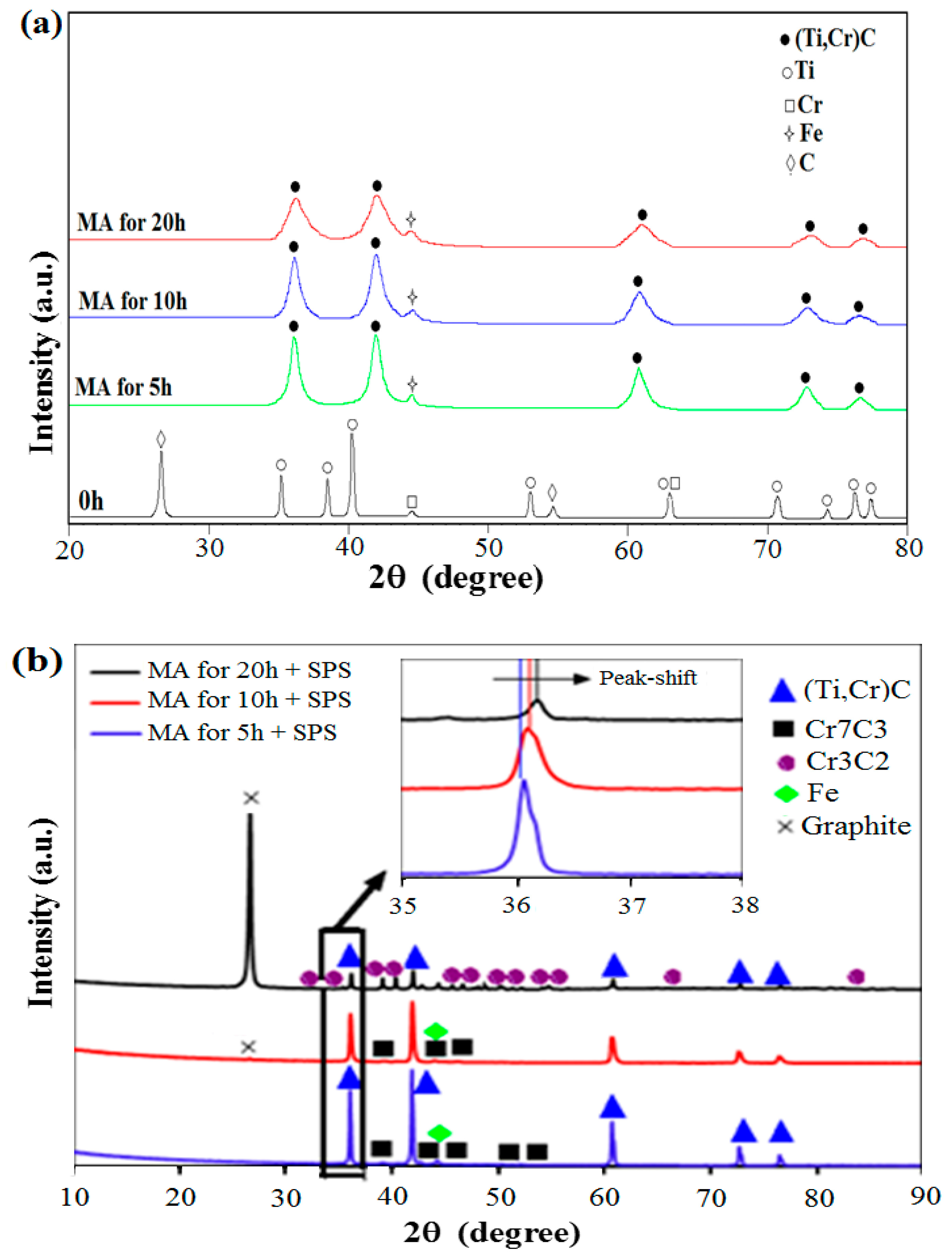
3.1. Characterization of Bulk Samples Prepared via SPS

XRD results of the milled powders and spark-plasma-sintered samples produced from different milling times are presented in Figure 1. As can be observed, the un-milled powder mixture’s XRD pattern, used as a reference, exhibits all of the expected Bragg peaks for the initial elements (Ti, Cr, and C). Nine Bragg peaks are visible in the Ti phase, and the remaining peaks belong to both the Cr and C phases. As can be seen from Figure 1a, there are just the (Ti,Cr)C phase, which crystallizes in the cubic system (NaCl-like FCC structure, space group Fm-3m), and iron (Fe) Bragg peaks between 5 and 20 h of milling. It was observed that the longer milling times had a significant impact on the Bragg diffraction peaks’ broadening and intensity. A small shift in the position of the Bragg diffraction peaks to higher 2-theta values is also observed. This demonstrates the formation of a nanostructured (Ti,Cr)C solid solution. We can infer from these MA settings that the formation of Ti0.9Cr0.1C is fully complete after 5 h of milling and that, thereafter, an increase in milling time beyond 5 h results in particle refinement with the preservation of the nanometric scale. It is interesting to note that the cell parameter and crystallite size obtained here for the composition (Ti0.9Cr0.1)C are very close to that of the composition (Ti0.8Cr0.2)C reported in our previous work [5]. The cell parameter decreases from 4.321 to 4.249 Å, and the crystallite size decreases from 22 to 11 nm when the ball milling time increases from 5 to 20 h.
The XRD patterns of the three densified samples are shown in Figure 1b. As can be seen, the major phase present in the three samples is the carbide (Ti,Cr)C (S.G: Fm-3m, a = 4.2990(1) Å; ICSD ref. code 98-005-3106). However, as shown in the figure inset, it is observed that the peak at around 2θ ≈ 36° is shifted towards the high diffraction angles when the applied milling time is increased from 5 to 20 h. This displacement indicates a depletion of (T,Cr)C in chromium, as has been shown by Kunrath et al. [39]. Thus, by depleting in chromium, the mixed carbide (Ti,Cr)C evolves towards the unsubstituted phase TiC.
Alongside the major phase (Ti,Cr)C, however, the appearance of a second phase is observed, the nature of which depends on the milling time. For samples prepared from 5 and 10 h milled powder, this phase corresponds to chromium carbide Cr7C3 (S.G: P63mc, a = 14.01009(1) Å, c = 4.5320(1) Å; ICSD ref. code 98-005-2289). In the case of the sample elaborated from 20 h milled powder, Cr3C2 (S.G: Pnma, a = 5.5250(1) Å, b = 2.8270(1) Å, c = 11.4680(1) Å; ICSD ref. code 98-015-1477) is formed instead of Cr7C3.
It can therefore be concluded that the SPS heat treatment transforms the solid-solution carbide (Ti,Cr)C into stable phases, namely, titanium carbide (TiC) and chromium carbides (Cr7C3 and Cr3C2). These results are in good agreement with those reported by Kunrath et al. in the case of Ti-Cr-C solid solution with low chromium amount [39] and with results reported on the equilibrium phases in the Ti-Cr-C system at temperature from 1300 to 2800 °C [40].
Two other phases foreign to the system are observed: α-Fe (S.G: Im-3m, a = 2.8870(1) Å; ICSD ref. code 98-018-0970) and the hexagonal graphite phase (S.G: P63/mmc, a = 2.4640(1) Å, c = 6.7110(1) Å; ICSD ref. code 98-007-6767). The presence of iron in a small proportion may come from the wear of the steel balls used for grinding. The presence of graphite could be attributed to the following reasons: (i) the elemental carbon initially added to the mixing powder to form a solid solution may not be completely dissolved in the structure and the residue may become graphitized [41]. (ii) It may be due to the separation of the (Ti,Cr)C solid solution during sintering, which indicates the difference in stoichiometry between the carbide phases that occur in MA followed by the SPS process [42]. (iii) Other carbon sources, such as graphite die, in the SPS equipment may ensure the free carbon [43].
Table 1 compares the crystallite size of the starting (Ti,Cr)C nanopowders along with the crystallite size of the same phase after SPS heat treatment.
As can be seen, the heat treatment via the SPS process induces a moderate magnification of the crystallite size. This promotes the production of dense and nanostructured materials [44].
Figure 2 illustrates the SEM images in backscattered electron (BSE) mode, as well as their EDX mapping analysis. Figure 2a presents the microstructure of the 5 h milled sample. The darker areas represented by points B and C, have 4.8 and 5.3% wt. chromium content, while the lighter points, A and D, have 20.8 and 19.6%, respectively. The gray region (TiCr) has a uniform distribution of the C phase, and a few bright regions exhibit Cr-rich carbide. A minor quantity of Fe in the sample milled for 5 h + SPS also showed up in some Cr-rich regions, namely, points A and D. Generally, the sample milled for 5 h + SPS shows uniform distribution of Ti, Cr, and C [41,42,45].
Figure 2b depicts the EDX mapping of the BSE-SEM image of the 10 h milled sample manufactured with SPS. When the EDX point results are compared, it becomes clear that the black zone represented by point H has a very high amount of graphite, which may be present in the system according to the above reasons, whereas the gray areas shown by points F and G consist of only TiC. The bright white regions are composed of the Cr-rich carbide phase, as illustrated in point E, and these zones are the only ones that have iron content for 10 h milled carbide. This can be explained by the dissolution of iron, which is included in the powders as an impurity with the increase in the milling time.
Figure 2c shows four specific regions in the BSE-SEM image of the 20 h milled sample produced via SPS. As in previous images, graphite is visible in the black sections, while TiC is present in the gray parts, as shown in points I and L. The white region depicted in point K, which is quite high compared to other samples, shows chromium carbide with an amount of iron. The dark gray region denotes the chromium carbide phases, which have nearly zero TiC and less iron than the whiter area. In addition, except the gray zone, which has a ratio at point L, there is limited titanium for the sample obtained from milled powder for 20 h. According to the XRD and EDX results, the sample obtained from milled powder for 20 h had the greatest iron concentration.
Finally, the BSE-SEM analyses are in good agreement with those carried out via X-ray diffraction. Both studies clearly show that the SPS process induces the decomposition of the TiCrC carbide into a composite consisting of several carbides, in particular TiC and chromium carbides. The composition of the composite seems to depend on the milling time. Increasing the milling time in preparing the initial powders induces greater decomposition of TiCrC and the formation of a phase (Ti1−xCrxC) increasingly poor in chromium besides chromium carbides.
The carbide’s densities and hardness values are depicted in Table 2. Relative densities are also shown along with the density values. Density and hardness values are similar in pellets that are milled for 5 and 20 h, while these are higher than that of pellet sample for 10 h of milling. Once more, it is evident from the hardness data that the bulk samples obtained from the powders milled for 5 and 20 h consist of average hardness values near to one another. The hardness and density values of the sample obtained from milled powder for 10 h are significantly lower than that of the other bulk samples. The average hardness values of 93.3 and 91.5 HRA for the bulk samples obtained from the powders milled for 5 and 20 h are close to those in the literature [46,47]. The low hardness of the bulk sample prepared from the powder milled for 10 h can be attributed to the low density. In spite of its high density, the reduced hardness for the sample milled for 20 h + SPS may be explained by an increase in the ratio of iron, a soft metal, as seen in the SEM-EDX and XRD results.
HRA hardness converted into Vickers hardness varies in the range from 800 to 1800 HV [48]. It should be noted that these values remain lower than reported by Abderrazak et al. for TiC carbide produced via a similar method combining MA and SPS (2700 HV) [49]. This can be due to the lower density observed for the materials obtained here and also the presence of foreign phases (iron and carbon) with lower hardness.

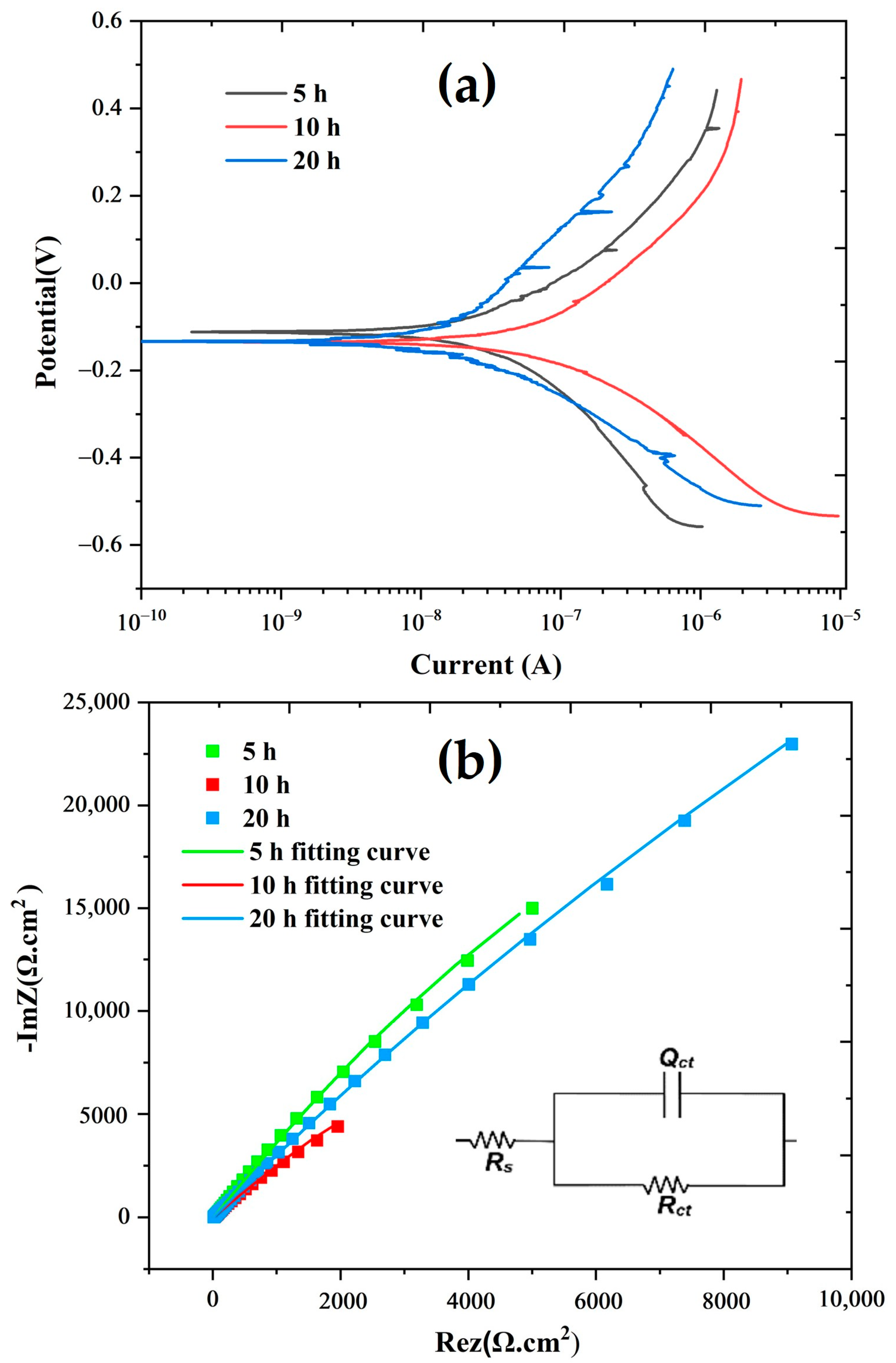
3.2. Electrochemical Properties of Bulk Samples Prepared via SPS

Tafel polarization curves, Nyquist plots, and electrical equivalent circuits are given in Figure 3, and the results of electrochemical corrosion tests are shown in Table 3. The corrosion tests were performed to predict prepared materials’ resistance to corrosion. All carbides indicated a very low corrosion rate. This is due to the strong corrosion resistance of carbides of titanium and chromium. It can be clearly comprehended that the sample (10 h + SPS) has the highest corrosion rate among all. The solubility of the Cr element in the TiC matrix increases as a result of the increase in the milling time. Although it is anticipated that an increase in the Cr ratio will reduce the rate of corrosion, the pores that develop due to the low density in particular act as corrosion zones and reduce corrosion resistance by boosting the surface area in contact with the solution, and the increase in porosity prevents the Cr2O3 layer from being continuous and hastens its deterioration [38,50,51,52,53]. The lowest corrosion rate and maximum polarization resistance were obtained in sample (20 h + SPS), as illustrated in Table 3. This is related to the increase in the Cr3C2 phase, whose solubility rises with milling time according to XRD and SEM/EDX results. Furthermore, this sample has a greater density than that of sample (10 h + SPS) and therefore it is assumed to contain a lower percentage of pores. This facilitates the formation of a continuous film of chromium oxide, a favorable factor to enhance protection against corrosion [51]. The corrosion resistance was also assessed using the EIS tests in addition to the Tafel polarization tests. The Nyquist plots in Figure 3b were fitted using the EC-lab program using the three-element circuit model. In this circuit model, Qct is the double-layer constant phase element, Rct is the charge transfer resistance, and Rs is the solution resistance. The strong corrosion resistance is closely correlated with the high charge transfer resistance [45,51,52,53,54]. So, considering this, as can be seen in Table 3 and Figure 3b, the corrosion resistance degree of the pellets in EIS tests is 20 h > 5 h > 10 h.
As shown in Table 3, SPS pure TiC presents the best corrosion resistance behaviour. Any addition of a foreign element, such as X (Ti, X)C or W in [55], and Cr in the present work, or the presence of a minor phase such as Ni3Al [55], does not improve corrosion resistance. It should however be noted that the substitution of Ti with Cr in the present work seems more beneficial than when Ti is substituted with W.
It is interesting to note that the results on the corrosion resistance are in good agreement with the BSE-SEM analyses of the different samples prepared via SPS as well as with the corresponding density measurements. Indeed, the sample (10 h + SPS) with the lowest corrosion resistance corresponds to the lowest density and therefore to the greatest porosity. In addition, this solid is a composite where a clear demixing between a pure TiC phase and chromium carbides is observed. The other samples (5 h + SPS) and (20 h + SPS) show a high density and a better distribution of chromium in all the compounds present in the composite. Such a distribution gives the materials a better resistance to corrosion, with chromium being known as a metal improving the resistance of alloys against oxidation.

4. Conclusions

Dense nanostructured carbides existing in ternary-system Ti-Cr-C were elaborated thanks to a two-steps method. First, a nanopowder of (Ti,Cr)C was obtained via a mechanical alloying process. Second, the as-obtained powders were submitted to the SPS process, leading to final dense materials. X-ray diffraction along with BSE-SEM analysis revealed that initial (Ti,Cr)C is a metastable phase that transforms under the SPS process into a composite material. Milling time to elaborate the starting nanopowder appears to be the main factor governing the nature of the obtained phases. For milling times of 5 or 10 h, Cr7C3 is obtained along with the major phase (Ti,Cr)C, while for 20 h, the phase Cr3C2 is obtained in addition to (Ti,Cr)C. Furthermore, it appears that the obtained (Ti,Cr)C after SPS becomes depleted in chromium when the milling time is increased.
Archimedes density tests and Rockwell hardness (HRA) tests revealed that the bulk sample obtained from the powder milled for 10 h has unsatisfactory mechanical characteristics, with values of 87.14% and 83.21 HRA, respectively, whereas bulk samples obtained from powders milled for 5 and 20 h had acceptable mechanical properties with a relative density of over 98% and hardness values of 93.3 ± 0.3 and 91.5 ± 0.4 HRA, respectively.
On the other hand, it is found that increasing the milling time up to 20 h increased the corrosion resistance (Icorr = 0.1270 µA/cm2, Rp = 395.63 kΩ.cm2, and Rct = 371.68 kΩ.cm2). This may due to the high density of the material and a better distribution of chromium in all the compounds present inside.

Author Contributions

Conceptualization, M.M., B.A. and N.J.; methodology, M.M., İ.E.D., B.A., F.S., M.A.B., M.K. and N.J.; validation, M.M., İ.E.D., B.A., M.K., M.A.B., F.S. and N.J.; formal analysis, M.M., İ.E.D., B.A. and N.J.; investigation, M.M., B.A., M.K., M.A.B., F.S. and N.J.; resources, M.M., İ.E.D., B.A. and N.J.; data curation, M.M., İ.E.D., B.A. and N.J.; writing—original draft preparation, M.M., İ.E.D., B.A. and M.K.; writing—review and editing, M.M., İ.E.D., B.A., M.K., M.A.B., F.S. and N.J.; visualization, M.M., İ.E.D., B.A., M.K., M.A.B., F.S. and N.J.; project administration, M.M. and N.J.; funding acquisition, M.M. All authors have read and agreed to the published version of the manuscript.

Funding

This research received no external funding.

Institutional Review Board Statement

Not applicable.

Informed Consent Statement

Not applicable.

Data Availability Statement

Not applicable.

Conflicts of Interest

The authors declare no conflict of interest.

References

  1. Mhadhbi, M.; Driss, M. Titanium Carbide: Synthesis, Properties and Applications. J. Brill. Eng. 2021, 2, 1–11. [Google Scholar] [CrossRef]
  2. Komratov, G.N. Oxidation Kinetics of Double Titanium-chromium Carbide and Chromium Carbide. Poroshk. Metall. 1999, 9–10, 52–57. [Google Scholar]
  3. Chen, K.; Zhao, L. Elastic Properties, Thermal Expansion Coefficients and Electronic Structures of Ti0.75X0.25C Carbides. J. Phys. Chem. Solids 2007, 68, 1805–1811. [Google Scholar] [CrossRef]
  4. Umanskii, A.P.; Lavrenko, V.A.; Chuprov, S.S.; Konoval, V.P. High-temperature Oxidation of Composites Based on Titanium Carbonitride and Double Titanium–chromium Carbide. Nov. Ogneup. 2006, 8, 42–46. [Google Scholar] [CrossRef]
  5. Mhadhbi, M.; Polkowski, W. Synthesis and Characterization of Mechanically Alloyed Nanostructured (Ti,Cr)C Carbide for Cutting Tools Application. Crystals 2022, 12, 1280. [Google Scholar] [CrossRef]
  6. Chuev, I.I.; Kovalev, D.Y. Effects of Titanium High-energy Ball Milling on the Solid-phase Reaction Ti+C. Mater. Chem. Phys. 2022, 283, 126025. [Google Scholar] [CrossRef]
  7. Zhang, L.; Liang, Y.; Gu, J.; Yan, X.; Li, X.; Yu, P.; Wang, L. Synthesis of Nano (Ti,W)C Powder with Preferred Orientation and Twin Boundary Structure. Adv. Powder Technol. 2022, 33, 103550. [Google Scholar] [CrossRef]
  8. Bandyopadhyay, S.; Dutta, H.; Pradhan, S.K. XRD and HRTEM Characterization of Mechanosynthesized Ti0.9W0.1C Cermet. J. Alloys Compd. 2013, 581, 710–716. [Google Scholar] [CrossRef]
  9. Li, F.; Wang, W.; Dang, W.; Xu, Z.; Zhao, K.; Tang, Y. Microstructural Features and Oxidation Resistance of (Ti, Zr)C Solid Solution Nanofibers Fabricated Using Polymeric Precursors. Ceram. Int. 2019, 45, 24941–24945. [Google Scholar] [CrossRef]
  10. Ke, D.; Pan, Y.; Wu, R.; Xu, Y.; Wang, P.; Wu, T. Effect of Initial Co Content on the Microstructure, Mechanical Properties and High-Temperature Oxidation Resistance of WCoB–TiC Ceramic Composites. Ceram. Int. 2018, 44, 1213–1219. [Google Scholar] [CrossRef]
  11. Yung, D.L.; Maaten, B.; Antonov, M.; Hussainova, I. Oxidation of Spark Plasma Sintered ZrC–Mo and ZrC–TiC Composites. Int. J. Refract. Metals Hard Mater. 2017, 66, 244–251. [Google Scholar] [CrossRef]
  12. Wang, Z.; Wang, J.; Xu, Y.; Yi, M.; Xiao, G.; Chen, Z.; Zhang, J.; Chen, H.; Xu, C. Microstructure and Mechanical Properties of (Ti,W)C Cermets Prepared by Ultrafast Spark Plasma Sintering. Ceram. Int. 2022, 48, 15613–15621. [Google Scholar] [CrossRef]
  13. Zhang, Z.; Fu, S.; Aversano, F.; Bortolotti, M.; Zhang, H.; Hu, C.; Grasso, S. Arc Melting: A Novel Method to Prepare Homogeneous Solid Solutions of Transition Metal Carbides (Zr, Ta, Hf). Ceram. Int. 2019, 45, 9316–9319. [Google Scholar] [CrossRef]
  14. Pellizzari, M.; Cipolloni, G. Tribological Behavior of Cu Based Materials Produced by Mechanical milling/Alloying and Spark Plasma Sintering. Wear 2017, 376–377, 958–967. [Google Scholar] [CrossRef]
  15. Dudina, D.V.; Vidyuk, T.M.; Gavrilov, A.I.; Ukhina, A.V.; Bokhonov, B.B.; Legan, M.A.; Matvienko, A.A.; Korchagin, M.A. Separating the Reaction and Spark Plasma Sintering Effects During the Formation of TiC–Cu Composites from Mechanically Milled Ti–C–3Cu Mixtures. Ceram. Int. 2021, 47, 12494–12504. [Google Scholar] [CrossRef]
  16. Esteki, S.; Saeidi, R.; Dini, G.; Milani, M. Fabrication of Silicon Carbide Ceramics by Combination of Slip Casting and Spark Plasma Sintering. Mater. Chem. Phys. 2023, 297, 127418. [Google Scholar] [CrossRef]
  17. Dudina, D.V.; Grigoreva, T.F.; Devyatkina, E.T.; Vosmerikov, S.V.; Ukhina, A.V.; Markushin, V.V.; Lyakhov, N.Z. Structural Features of Tantalum Carbide-copper Composites Obtained by Liquid Phase-assisted Spark Plasma Sintering. Ceram. Int. 2022, 48, 32556–32560. [Google Scholar] [CrossRef]
  18. Lamim, D.D.; de Oliveira, H.C.P.; Batista, A.C.; Guimarães, R.S.; Filgueira, M. Use of Ti in Hard Metal Alloys—Part I: Structural and Microstructural Analysis. Mater. Werkst. 2010, 41, 198–201. [Google Scholar] [CrossRef]
  19. Ouar, N.; Bousnina, M.A.; Schoenstein, F.; Mercone, S.; Brinza, O.; Farhat, S.; Jouini, N. Spark Plasma Sintering of Co80Ni20 Nanopowders Synthesized by Polyol Process and their Magnetic and Mechanical Properties. J. Alloys Compd. 2014, 615, S269–S275. [Google Scholar] [CrossRef]
  20. Fang, G.; Tang, H.; Ren, Z.; Cheng, Y.; Yu, Y.; Wang, L.; Li, T.; Zhang, Y.; Qiao, Z. Effect of Grain Size on Oxidation Resistance of WC–6wt% Co Cemented Carbide Sintered by Spark Plasma Sintering. Int. J. Refract. Met. Hard Mater. 2023, 111, 106108. [Google Scholar] [CrossRef]
  21. Podbolotov, K.; Moskovskikh, D.; Abedi, M.; Suvorova, V.; Nepapushev, A.; Ostrikov, K.; Khort, A. Low-temperature Reactive Spark Plasma Sintering of Dense SiC–Ti3SiC2 Ceramics. J. Eur. Ceram. Soc. 2023, 43, 1343–1351. [Google Scholar] [CrossRef]
  22. Tripathy, H.; Sudha, C.; Thomas Paul, V.; Thirumurugesan, R.; Prasanthi, T.N.; Sundar, R.; Vijayashanthi, N.; Parameswaran, P.; Raju, S. High Temperature Thermophysical Properties of Spark Plasma Sintered Tungsten Carbide. Int. J. Refract. Met. Hard Mater. 2022, 104, 105804. [Google Scholar] [CrossRef]
  23. Ke, B.; Ji, W.; Zou, J.; Wang, W.; Fu, Z. Densification Mechanism, Microstructure and Mechanical Properties of ZrC Ceramics Prepared by High–pressure Spark Plasma Sintering. J. Eur. Ceram. Soc. 2023, 43, 3053–3061. [Google Scholar] [CrossRef]
  24. Zhao, Z.; Wang, C.; Yang, L.; Cheng, Y.; Cai, Z.; Mehrizi, M.Z. Microstructure and Properties of NiAl/TiC Composite Synthesized by Spark Plasma Sintering of Mechanically Activated Elemental Powders. Ceram. Int. 2023, 49, 15710–15716. [Google Scholar] [CrossRef]
  25. Lee, J.; Jang, K.; Lee, S.; Mo, C.B.; Kim, H.; Park, K.R.; Kim, J.; Bang, J.; Jung, I.C.; Kim, J.C.; et al. Mechanical Properties of TiC Reinforced MgO–ZrO2 Composites via Spark Plasma Sintering. Ceram. Int. 2023; in press. [Google Scholar] [CrossRef]
  26. Lou, Z.; Li, Y.; Zou, Q.; Luo, W.; Gu, H.; Li, Z.; Luo, Y. In-situ Fabrication and Characterization of TiC Matrix Composite Reinforced by SiC and Ti3SiC2. Ceram. Int. 2023; in press. [Google Scholar] [CrossRef]
  27. Rodriguez-Carvajal, J. Recent Advances in Magnetic Structure Determination by Neutron Powder Diffraction. Phys. B 1993, 192, 55–69. [Google Scholar] [CrossRef]
  28. Rietveld, H.M. Line Profiles of Neutron Powder-Diffraction Peaks for Structure Refinement. Acta Cryst. 1967, 22, 151–152. [Google Scholar] [CrossRef]
  29. Rietveld, H.M. A Profile Refinement Method for Nuclear and Magnetic Structures. J. Appl. Cryst. 1969, 2, 65–71. [Google Scholar] [CrossRef]
  30. Wiles, D.B.; Young, R.A. A New Computer Program for Rietveld Analysis of X-ray Powder Diffraction Patterns. J. Appl. Cryst. 1981, 14, 149–151. [Google Scholar] [CrossRef]
  31. Young, R.A.; Wiles, D.B. Profile Shape Functions in Rietveld Refinements. J. Appl. Cryst. 1982, 15, 430–438. [Google Scholar] [CrossRef]
  32. Young, R.A. (Ed.) The Rietveld Method; Oxford University Press/IUCr: Oxford, UK, 1996; pp. 1–38. [Google Scholar]
  33. Lutterotti, L.; Scardi, P.; Maistrelli, P. LSI-a Computer Program for Simultaneous Refinement of Material Structure and Microstructure. J. Appl. Cryst. 1992, 25, 459–462. [Google Scholar] [CrossRef]
  34. Ghosh, B.; Dutta, H.; Pradhan, S.K. Microstructure Characterization of Nanocrystalline Ni3C Synthesized by High-energy Ball Milling. J. Alloys Comp. 2009, 479, 193–200. [Google Scholar] [CrossRef]
  35. Warren, B.E. X-ray Diffraction; Chapter 13; Addison-Wesley, Reading: Boston, MA, USA, 1969. [Google Scholar]
  36. Oldfield, J.W. Electrochemical Theory of Galvanic Corrosion, STP978 Galvanic Corrosion; Hack, H.P., Ed.; ASTM Int. West Conshohocken: Conshohocken, PA, USA, 1988; pp. 5–22. [Google Scholar]
  37. Nelson, E.E. Discussion of the Mechanism of Passivating-Type Inhibitors [M. Stern (pp. 638–647, Vol. 105)]. J. Electrochem. Soc. 1959, 106, 540. [Google Scholar] [CrossRef]
  38. Luiz, L.A.; de Andrade, J.; Pesqueira, C.M.; Siqueira, I.B.d.A.F.; Sucharski, G.B.; de Sousa, M.J. Corrosion Behavior and Galvanic Corrosion Resistance of WC and Cr3C2 Cermet Coatings in Madeira River Water. J. Therm. Spray Technol. 2021, 30, 205–221. [Google Scholar] [CrossRef]
  39. Kunrath, A.O.; Reimanis, I.E.; Moore, J.J. Microstructural Evolution of Titanium Carbide–Chromium Carbide (TiC–Cr3C2) Composites Produced via Combustion Synthesis. J. Am. Ceram. Soc. 2002, 85, 1285–1290. [Google Scholar] [CrossRef]
  40. Booker, P.H.; Kunrath, A.O.; Hepworth, M.T. Experimental Determination of the Ternary Diagram of the Ti-Cr-C System. Acta Mater. 1997, 45, 1625–1632. [Google Scholar] [CrossRef]
  41. Feng, P.; Xiong, W.; Yu, L.; Zheng, Y.; Xia, Y. Phase Evolution and Microstructure Characteristics of Ultrafine Ti(C,N) –based Cermet by Spark Plasma Sintering. Int. J. Refract. Met. Hard Mater. 2004, 22, 133–138. [Google Scholar] [CrossRef]
  42. Soundaraj, P.V.; Sembulingam, S.S.; Shanmugavel, B.P. On the Role of B4C on Hardness and Toughness of TiCN–SiC–TiN–Cr3C2–Co Cermet. Int. J. Refract. Met. Hard Mater. 2020, 90, 105252. [Google Scholar] [CrossRef]
  43. Soria, T.; Lopez, B.; Lozada, L.; Moseley, S.; Alveen, P.; Elsen, M.; Müller-Grunz, A.; Magin, M.; Useldinger, R.; Sánchez, J.M. An Investigation into the Effects of HIP After Sintering of WC–ZrC–Co–Cr3C2 Cemented Carbides. Int. J. Refract. Met. Hard Mater. 2020, 87, 105164. [Google Scholar] [CrossRef]
  44. Bousnina, M.A.; Schoenstein, F.; Mercone, S.; Jouini, N. From Ni–P Metastable Alloy Nanoparticles to Bulk Submicrometer Grain-Sized MMCs with Tunable Mechanical and Magnetic Properties. Metals. 2020, 10, 112. [Google Scholar] [CrossRef]
  45. Shankar, E.; Prabu, S.B.; Padmanabhan, K.A. Mechanical Properties and Microstructures of TiCN/nano-TiB2/TiN Cermets Prepared by Spark Plasma Sintering. Ceram. Int. 2018, 44, 9384–9394. [Google Scholar] [CrossRef]
  46. Xiong, H.; Guo, Y.; Li, Z.; Zhou, K. New Production of (Ti, W)C–based Cermets Toughened by In-situ Formed WC and Twinned (Ti, W)C Platelets: Carbonization of The Nix(Ti0.6, W0.4)4C–type η Phases. J. Alloys Compd. 2018, 731, 253–263. [Google Scholar] [CrossRef]
  47. Zhang, L.; Ling, Q.; Gu, J.; Zhong, Z.; Long, J.; Wang, C. Strengthening and Toughening of Ti(C,N)–based Cermets: (Ti,W)C Additive Design and The Mechanism. Int. J. Refract. Met. Hard Mater. 2022, 103, 105758. [Google Scholar] [CrossRef]
  48. Available online: https://www.gordonengland.co.uk/hardness/hvconv.htm (accessed on 9 January 2023).
  49. Abderrazak, H.; Schoenstein, F.; Abdellaoui, M.; Jouini, N. Spark Plasma Sintering Consolidation of Nanostructured TiC Prepared by Mechanical Alloying. Int. J. Refract. Met. Hard Mater. 2011, 29, 170–176. [Google Scholar] [CrossRef]
  50. Wan, W.; Xiong, J.; Yang, M.; Guo, Z.; Dong, G.; Yi, C. Effects of Cr3C2 Addition on the Corrosion Behavior of Ti(C, N)-based Cermets. Int. J. Refract. Met. Hard Mater. 2012, 31, 179–186. [Google Scholar] [CrossRef]
  51. Chen, S.; Xiong, W.; Yao, Z.; Zhang, G.; Chen, X.; Huang, B.; Yang, Q. Corrosion Behavior of Ti(C,N)-Ni/Cr Cermets in H2SO4 Solution. Int. J. Refract. Met. Hard Mater. 2014, 47, 139–144. [Google Scholar] [CrossRef]
  52. Vorotilo, S.; Kiryukhantsev-Korneev, P.V.; Seplyarskii, B.S.; Kochetkov, R.A.; Abzalov, N.I.; Kovalev, I.D.; Lisina, T.G.; Zaitsev, A.A. (Ti,Cr)C–Based Cermets with Varied NiCr Binder Content via Elemental SHS for Perspective Cutting Tools. Crystals 2020, 10, 412. [Google Scholar] [CrossRef]
  53. Kong, D.; Dong, C.; Ni, X.; Li, X. Corrosion of Metallic Materials Fabricated by Selective Laser Melting. NPJ Mater. Degrad. 2019, 3, 24. [Google Scholar] [CrossRef]
  54. He, L.; Gao, Y.; Li, Y.; Liu, Z.; Huo, X.; Zhai, W. Effect of Milling Time on Powder’s Structure Evolution of Ti(C,N)–304 Stainless Steel Cermet. Mater. Res. Express 2018, 5, 36516. [Google Scholar] [CrossRef]
  55. Memarrashidi, Z.; Plucknett, K.P. Factors Influencing the Aqueous Electrochemical Response of TiC–Ni3Al Cermets. J. Mater. Res. 2017, 32, 3333–3343. [Google Scholar] [CrossRef]
Figure 1. (a) XRD patterns of TiCrC powders before and after different milling times, and (b) XRD patterns of TiCrC samples obtained by SPS.
Metals 13 01040 g001
Figure 2. BSE-SEM analyses and EDX-mapping images of the carbides prepared via SPS for different milling times: (a) 5 h, (b) 10 h, and (c) 20 h.
Metals 13 01040 g002aMetals 13 01040 g002b
Figure 3. (a) Potentiodynamic polarization results of carbides, and (b) Nyquist plots of EIS results and equivalent circuit used for fitting.
Metals 13 01040 g003
Table 1. The crystallite size of the starting (Ti,Cr)C nanopowders after MA and after SPS process.
Milling Time (h)Crystallite Size in
Powder (nm)
Crystallite Size in SPS Sample (nm)
522219
101558
2011100
Table 2. Density and microhardness values of the prepared carbides.
SampleDensity (g/cm3)Relative Density (%)Rockwell Hardness (HRA)
5 h + SPS5.02998.4393.3 ± 0.3
10 h + SPS4.45287.1483.2 ± 1.7
20 h + SPS5.03398.5191.5 ± 0.4
Table 3. Electrochemical test results of the prepared carbides.
SampleEcorr (V)icorr (µA/cm2)BetaA (V/decade)BetaC (V/decade)CR
(mm/year)
Rp
(kΩ.cm2)
Rct
(kΩ.cm2)
5 h + SPS−0.1120.27420.28190.32950.00236240.57302.24
10 h + SPS−0.1350.56540.31890.21320.0048798.12128.99
20 h + SPS−0.1330.12700.36980.16850.00110395.63371.68
TiC-Ni3Al [55]−0.0490.0137--0.00045--
SPS-TiC pure [55]0.0050.0422--0.00029--
SPS-TiWC [55]−0.1761.28--0.00781 -
Ecorr: corrosion potential; icorr: corrosion current density; BetaA: anodic Tafel slope; BetaC: cathodic Tafel slope; CR: corrosion rate; Rp: polarization resistance; Rct: charge transfer resistance.
Disclaimer/Publisher’s Note: The statements, opinions and data contained in all publications are solely those of the individual author(s) and contributor(s) and not of MDPI and/or the editor(s). MDPI and/or the editor(s) disclaim responsibility for any injury to people or property resulting from any ideas, methods, instructions or products referred to in the content.

