Article

Quantifying Co-Deformation Effects in Metallic Laminates by Loading–Unloading–Reloading Tensile Tests

by
Philip Manuel Pohl
1,2,
Moritz Kuglstatter
1,
Mathias Göken
1,2 and
Heinz Werner Höppel
1,2,*
1
Materials Science & Engineering, Institute I, Friedrich-Alexander-Universität Erlangen-Nürnberg (FAU), Martensstraße 5, 91058 Erlangen, Germany
2
Joint Institute for New Materials and Processes (ZMP), Friedrich-Alexander-Universität Erlangen-Nürnberg (FAU), Mack-Straße 81, 90762 Fürth, Germany
*
Author to whom correspondence should be addressed.
Metals 2023, 13(6), 1049; https://doi.org/10.3390/met13061049
Submission received: 31 March 2023 / Revised: 5 May 2023 / Accepted: 22 May 2023 / Published: 30 May 2023

Abstract

:
Heterostructured materials such as metallic laminates (LMCs) can be specifically tailored to showcase significantly increased mechanical behavior based on the hetero-deformation-induced (HDI) strengthening effect caused by the co-deformation at the vicinity of interfaces. This study introduces a new approach to quantify these co-deformation effects in metallic laminates by characterizing the behavior of inelastic back strain upon unloading. Experimentally, the inelastic back strain (IBS) is determined by cyclic loading–unloading–reloading (LUR) tensile tests. Compared to a linear rule of mixture (ROM) approximation used as a reference, additional amounts of inelastic back strain were measured for different metallic laminate systems, strongly depending on the dissimilarities of yield strength and elastic moduli of constituents and the interface density in the laminates. Conducting finite element analysis, the distribution of residual plastic strain was investigated for the different metallic laminates used in this study. Based on this, a schematic overview of the spatial distribution of the hetero-deformation zone for metallic laminates with dissimilar yield strength and elastic moduli is derived, summarizing the results of this study. As most mechanical components are subject to cyclic stresses during the application, the method provided in this study to characterize the co-deformation behavior of metallic laminates in the microyielding regime enables valuable insights into mechanisms affecting the cyclic deformation behavior of metallic laminates for future applications.

1. Introduction

Subject to intensive research activities in recent years, heterostructured materials present a new class of materials showcasing superior functional and mechanical properties over homogeneous materials [1,2,3,4,5]. Heterostructured materials are defined as materials containing heterogeneous zones on a micro- or mesostructural level with vastly different mechanical and/or physical properties [3]. Based on synergistic interaction and coupling effects between the heterogeneous zones, improved mechanical and functional trade-off properties have been reported, such as strength–ductility [6,7] and magnetization–coercivity [8,9]. Depending on the morphology of the heterogeneous zones, heterostructured materials can be divided into different categories, including harmonic [10,11,12], gradient [13,14], bimodal [15,16] or laminated materials [17,18,19]. In heterostructured materials, the heterogeneous zones can consist, for instance, of mechanically soft and hard zones separated by boundaries such as grain boundaries or interfaces. Subjected to plastic deformation, these heterogeneous soft and strong zones deform inhomogeneously. In terms of cyclic deformation, different models have been established to describe the co-deformation behavior of mechanically heterogeneous materials. A comprehensive review is provided by Skelton, Maier and Christ [20], describing the relationship between the Masing model, Ramberg–Osgood relation and Bauschinger effect in the context of cyclic stress–strain behavior. A further model describing the co-deformation behavior based on local interaction at the boundary between soft and hard domains in heterostructured materials has been proposed recently by Zhu and Wu [21]. Upon tensile deformation, a dislocation network consisting of geometrically necessary dislocations piled up at the interface is formed in the softer domain to compensate for the necessary co-deformation. This creates forward stress in the strong domain and back stress in the soft domain. Gradients in stress and strain at the vicinity of the boundaries/interfaces are formed, creating the hetero-deformation zone or interface-affected zone [22]. The collective stress created by forward and backward stress is interpreted as hetero-deformation-induced (HDI) stress. To determine the HDI strengthening effect for heterostructured materials, the authors propose an experimental method based on tensile cyclic loading–unloading–reloading (LUR) tests [1,23,24]. A similar experimental approach based on cyclic tensile LUR tests in the microyielding regime was used by Mughrabi and Höppel [25,26,27] to evaluate the inelastic back strain upon unloading in ultrafine-grained and conventionally grained materials. The inelastic back strain was reported to be significantly higher for ultrafine-grained and nanocrystalline pure metals. Similar to the recent model by Zhu and Wu for heterostructured materials, the microstructural mechanism behind this was explained by the microscopic forward/back flow of geometrically necessary dislocations piled up at the grain boundaries during the unloading/reloading segments [25,28,29]. In conclusion, as the inelastic back strain is very sensitive to microstructural changes, cyclic tensile LUR tests are a promising experimental approach to study influences on the deformation behavior of heterostructured materials.
In this study, we evaluate a concept based on the inelastic back strain as a method to quantify co-deformation effects emerging at the hetero-deformation zones in metallic laminates varying in mechanical properties and interface density.

2. Materials and Methods

2.1. Laminated Metallic Composites and Monolithic Materials: Processing and Overview

Six different types of laminated metallic composites were produced by means of the accumulative roll-bonding (ARB) process to evaluate co-deformation effects at the vicinity of interfaces in metallic laminates caused by dissimilar (a) yield strength, (b) elastic modulus and (c) combined dissimilarities in yield strength as well as elastic modulus. Additionally, the role of interface density was studied. As a reference, constituent monolithic materials were produced accordingly. The chemical composition of all materials used in this study is listed in Table 1.
The utilized materials include commercially pure aluminum AA1050, the solid-solution-strengthened aluminum alloys AA5005 and AA5754, the high-purity copper grades Cu-OFE (oxygen-free electronic) and Cu-DHP (deoxidized high phosphorus), and the interstitial free deep-drawing steel DC05.
All laminated composites and monolithic materials were roll bonded on a four-high rolling mill (BW 300, Carl Wezel, Mühlacker, Germany). Prior to each roll-bonding step, the sheet metal surfaces were cleaned with acetone as well as wire brushed to remove oxide layers and achieve sufficient bonding. To study the influence of dissimilar mechanical properties on co-deformation effects, different Al/Al-laminates (AA5005/AA5754 and AA1050/AA5754) and Al/Cu-laminates (AA5754/Cu-DHP and AA1050/Cu-DHP) and the respective monolithic constituents were produced using three ARB cycles (N3). Prior to each roll-bonding step, the laminates and monolithic materials were fully recrystallized for 2 h at 365 °C using ambient atmosphere for the Al/Al-laminates and argon atmosphere for the Al/Cu-laminates. Subsequently, the sheets were stacked with an alternating sequence of the respective constituent materials and roll bonded at a nominal thickness reduction of 50% per ARB cycle at ambient conditions and halved in length afterwards. These steps were repeated three times, resulting in a respective total sheet thickness of 3.75 mm after three roll-bonding steps. Cross-sections of the laminate architectures are shown in Figure 1a.
To study the influence of interface density on co-deformation effects, two Cu/Fe-laminates (Cu-OFE/DC05) were produced using four (N4) and eight (N8) ARB cycles, respectively. For the first cycle, three sheets with an initial sheet thickness of 2.0 mm were stacked in a sequence of Cu/Fe/Cu and roll bonded. Subsequently, an additional cold rolling step was performed on the bonded laminate. The combination of these two steps can be treated as equivalent to a single roll-bonding cycle (N1) with a nominal thickness reduction of 66%. Using this two-stepped approach, sufficient bonding was achieved while minimizing edge cracking of the sheets and maintaining a nominal laminate sheet thickness of 2.0 mm after each roll-bonding cycle. For the second cycle (N2), three N1 laminate sheets were stacked and roll bonded using the two-stepped approach described above. These steps were repeated four and eight times to produce the Cu/Fe N4 and N8 laminates. After every second roll-bonding step, an intermediate recrystallization heat treatment for 30 min at 700 °C was performed using argon atmosphere. Thus, both the Cu/Fe N4 and N8 laminate were rolled for an additional two ARB cycles since their last recrystallization heat treatment. Consequently, the evolution of the microstructure and local mechanical properties due to cold working can be considered comparable between these two laminates. The nominal interface density ρIF was calculated at about 40 mm−1 for the Cu/Fe N4 laminate and about 3280 mm−1 for the Cu/Fe N8 laminate. Scanning electron microscope (SEM) cross-sections of the laminate architectures are shown in Figure 1b.
Based on the cross-sections of the laminates shown in Figure 1, the volume fractions of the laminate constituents were calculated as: AA5005/AA5754—48.1%/51.9%, AA1050/AA5754—48.9%/51.1%, AA5754/Cu-DHP—37.8%/62.2%, AA1050/Cu-DHP—51.4%/48.6%, Cu-OFE/DC05 N4—65.9%/34.1% and Cu-OFE/DC05 N8—65.8%/34.2%.

2.2. Cyclic Loading–Unloading–Reloading (LUR) Tensile Tests

The cyclic deformation behavior in the microyielding regime was determined by conducting cyclic loading–unloading–reloading (LUR) tensile experiments. Tensile test specimens were machined in transverse direction from the ARB-processed laminated metallic composites and monolithic materials. The nominal cross-section was 2.00 × 3.75 mm2 for the Cu-OFE/DC05 laminate systems and 3.75 × 3.75 mm2 for all other materials and the gauge length was 10 mm, respectively. The specimens were tested on a servohydraulic testing machine (MTS810, MTS System Corporation, Eden Prairie, MN, USA). The force was measured using a 10 kN load cell and the stress was determined from the cross-section area. A clip-on extensometer with a measurement range of ±2 mm was used to measure the strain. The specimens were tested conducting periodic loading and unloading segments at a constant stress loading/unloading rate of 1 MPa/s. For the first loading segment, a maximum stress of 10 MPa (20 MPa for the Cu-OFE/DC05 laminate systems) was applied before unloading. The maximum stress for each subsequent loading segment was increased by 10 MPa (20 MPa for the Cu-OFE/DC05 laminate systems) with respect to the prior loading segment. The tests were terminated after exceeding a measured plastic strain of εpl > 0.003 at the end of an unloading segment. For each material investigated, at least three specimens were tested.

2.3. Non-Linear Elastic Behavior, Inelastic Back Strain and Micro Yield Strength

The elastic behavior of a solid can be described by the change in potential energy resulting from the displacement of the interatomic spacing from the equilibrium state. The potential energy is defined by superposition of the repulsive and attractive forces acting on two neighboring atoms, resulting in an anharmonic potential (see Figure 2a). Consequently, the description of the elastic behavior using a linear relationship between stress σ and strain ε (Hooke’s law) is strictly only valid for infinitesimal small strains. An improved approximation for the elastic behavior for small strains can be obtained by describing the potential energy including the third-order term [30]. This results in a quadratic expression of Hooke’s law by introducing a second-order term:
σ = E 0 · ε e l + k · ε e l 2
with E0 being the elastic modulus and k being a constant. Using this improved approximation, the elastic behavior of a material can be characterized by a stress-dependent differential elastic modulus ED(σ) (see Figure 2a) as proposed by Sommer, Christ and Mughrabi [31]:
E D σ = E 0 2 + 4 k σ
with lim ε e l 0 E D = E 0 .
For each LUR experiment, the differential modulus ED(σ) was determined upon unloading as a function of the maximum stress applied for each segment. Using linear regression, the elastic modulus E0 and the constant k characterizing the stress dependency were obtained for each test as shown in Figure 2b.
Consequently, the normalized plastic strain εpl, nl correcting for the non-linear, stress-dependent elastic behavior can be calculated as:
ε p l , n l = ε t o t 2 σ E 0 + E D σ = ε t o t 2 σ E 0 + E 0 2 + 4 k σ
with εtot being the total strain measured by the strain gauge. Figure 2c compares the results of an exemplary loading–unloading–reloading experiment with and without the correction for non-linear elastic behavior. As can be seen, the stress–strain curves deviate from one another significantly at elevated stress. By calculating the difference between the maximum normalized strain obtained upon unloading and the residual plastic strain at zero remotely applied stress, the inelastic back strain (IBS) can be determined for each unloading segment of the LUR experiment.
The transition from non-linear elastic behavior to microyielding behavior of the investigated materials was characterized by determining the micro yield strength σY from the cyclic LUR tests (see Figure 2d). Therefore, upon onset of residual plastic strain after a given unloading segment (1), the micro yield strength σY of the respective specimens was determined as the mean value of the maximum stress applied in the previous (2) and the penultimate loading segment (3). Using this approach, the micro yield strength σY (4) could be determined precisely within an accuracy of ±5 MPa (±10 MPa for the Cu-OFE/DC05 laminate systems) for each sample, depending on the chosen step size of loading segments for the LUR tests (see Section 2.2). This analysis was performed for all specimens tested, and the micro yield strength σY was calculated as the average of all tested specimens within one material.
For each LUR test on laminated and monolithic materials, a continuous stress–strain curve was generated using the respective loading maxima of each loading segment (see Figure 2d) to adequately compare the microyielding behavior of the different materials.

2.4. Finite Element Analysis (FEA) of the Residual Plastic Strain Distribution

To evaluate the distribution of residual plastic strain within the layers of the different laminate systems in a qualitative manner, finite element analysis (Abaqus FEA, Dassault Systèmes, Vélizy-Villacoublay, France) was conducted. A 2D model was created with a gauge length of 10 mm and width of 3.75 mm to simulate the tensile test specimen used in the cyclic LUR tests. The third dimension was included by plain strain condition with a thickness of 3.75 mm. The FE model was partitioned into sections, representing the architecture of each metallic laminate system (see Figure 3a).
The elastic (Young’s modulus) and plastic material behavior (true stress σtrue and corresponding plastic strain εpl) provided by the continuous stress–strain curves derived from the cyclic tensile loading/unloading/reloading experiments (see Figure 2d) for the monolithic materials was used as input for the simulation and assigned to the individual sections (layers) of the model.
Using the symmetry of the specimen geometry and the displacement (u1 = 0) and rotation (uR3 = 0) boundary conditions at the symmetry plane, only half of the tensile test specimen’s gauge length was modeled, reducing the simulation runtime. The loading F was applied to a reference point, representing the front surface by a surface-based coupling constraint using continuum distribution.
The FE model was loaded to a stress level corresponding to a plastic strain εpl, LMC of 0.001 as predicted by a linear rule of mixture approximation based on the laminated composites’ monolithic constituents and subsequently unloaded. This loading procedure for the finite element model is described schematically in Figure 3b.
The model was meshed using 17,280 fully integrated, quadratic 8-node plain strain elements (CPE8) selected from the Abaqus two-dimensional solid element library. After the unloading step, the residual strain profile across all layers was determined at the symmetry plane in the direction of loading (εpl, xx). An average value εpl was calculated for each constituent material to evaluate the distribution of residual strain qualitatively.

3. Results

The microyielding behavior of the different monolithic materials and laminated composites was studied by conducting cyclic tensile loading–unloading–reloading (LUR) experiments. Using this experimental approach, the characteristics of mechanical behavior such as the onset of plastic deformation, elastic modulus or hardening behavior can be determined precisely. Additionally, microstructural aspects regarding the deformation behavior as apparent by the evolution of inelastic back strain upon unloading or the stress relaxation upon reloading can be studied precisely in the microyielding regime.

3.1. Evaluation of Mechanical Microyielding Behavior and Properties of Metallic Laminates

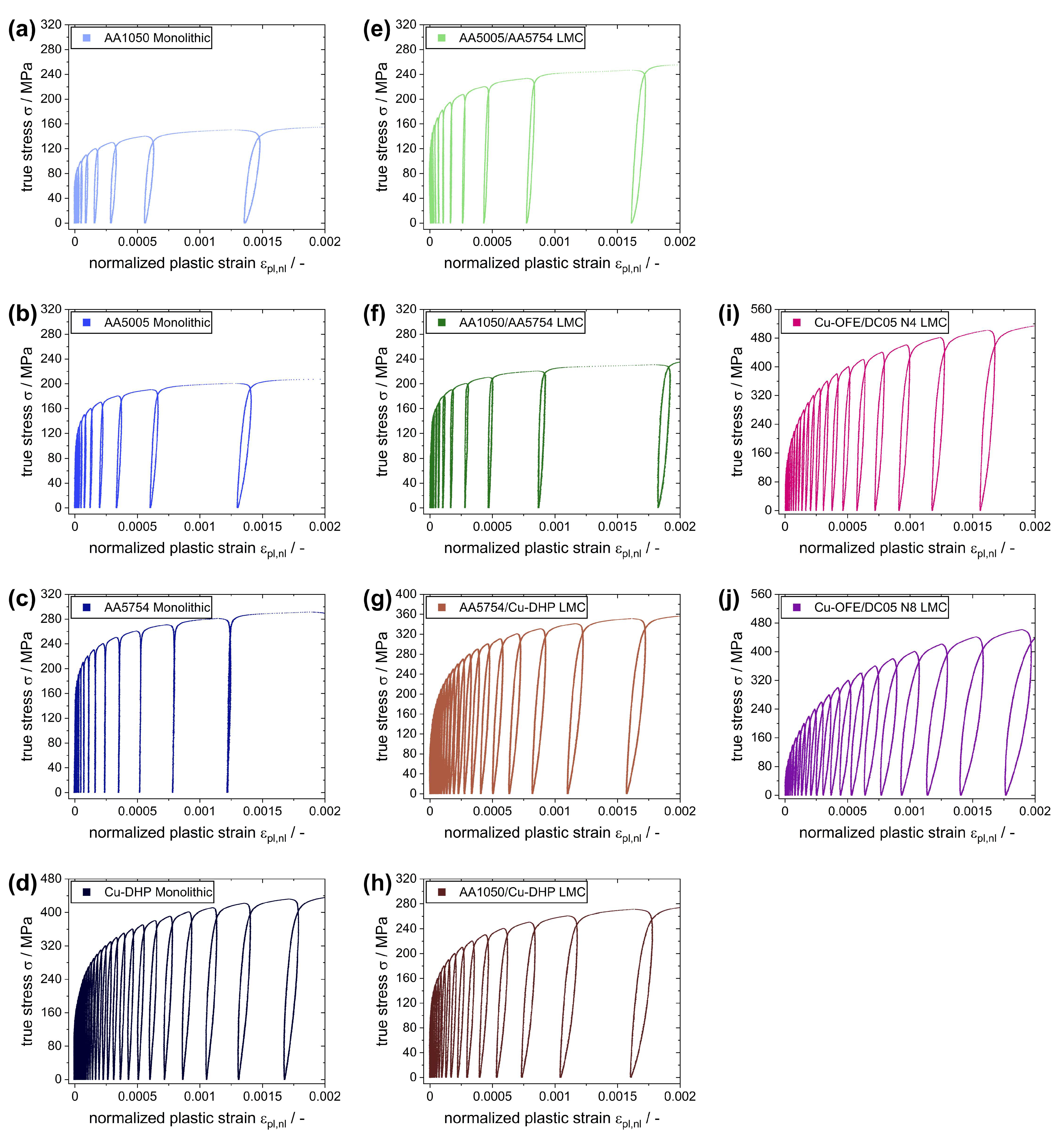
An overview of the stress–strain behavior of the investigated materials in the microyielding regime is shown in Figure 4. The data have been corrected for non-linear elastic, i.e., stress-dependent, behavior and are hence plotted as true stress σ versus normalized plastic strain εpl, nl. Figure 4a–d depicts the stress–strain behavior of the monolithic materials and Figure 4e–j of the different metallic laminates. One exemplary curve was chosen for each investigated monolithic and laminated material.
The following mechanical properties were determined from the tensile LUR tests for each monolithic and laminated material system: the elastic modulus E, the micro yield strength σY at the onset of plastic deformation and the strength σY0.2 at respective plastic strains εpl, nl of 0.002 (0.2%). The results are summarized in Table 2. As can be seen, AA1050 is the softest material with a micro yield strength of 63 MPa, followed by AA5005 with 110 MPa. Both the solid-solution-strengthened aluminum alloy AA5754 and commercially pure copper Cu-DHP were processed to exhibit similar micro yield strength σY of 147 MPa and 141 MPa, respectively. The copper material, however, exhibits substantially higher strain hardening behavior compared to the AA5754 alloys, as indicated by the higher yield strength σY0.2 of 433 MPa compared to 290 MPa for AA5754.
The micro yield strength values measured for both heterogeneous Al-laminates (118 MPa for AA5005/AA5754 and 83 MPa for AA1050/AA5754) are marginally bigger than the micro yield strength of the respective softer constituents. As the elastic moduli of all three monolithic aluminum materials were determined to be essentially the same (see Table 2), the co-deformation behavior of the heterogeneous Al-laminates can be assumed to be uniform up until the point of onsetting plastic deformation in the respective softer material. Consequently, the micro yield strength σY of the heterogeneous Al-laminates should be about the same as the respective softer monolithic material. This assumption, however, neglects microstructural inhomogeneities in metallic laminates caused by the accumulative roll-bonding (ARB) processing history. This includes the formation of an interface-affected zone (IAZ) [22,32] with severe grain refinement due to higher strains at the interfaces caused by the necessary co-deformation. The additional strengthening effect of the interface-affected zone can be a possible explanation for the discrepancy between the onset of plastic deformation (micro yield strength σY) in the laminated composites compared to their respective softer monolithic constituents.
The elastic modulus E of the monolithic copper (Cu-DHP) determined experimentally at 138 GPa is significantly higher than the elastic modulus of the aluminum alloys (around 70 GPa). In the case of the Al/Cu-laminates, this leads to stress shielding of the aluminum layers upon loading as stress is distributed into the stiffer Cu-layers of the laminated composite. Consequently, a higher micro yield strength σY is measured for the AA1050/Cu-DHP laminate compared to monolithic AA1050 (see Table 2) as the onset of plastic deformation is occurring in the softer but stress-shielded AA1050 layers. In the case of the AA5754/Cu-DHP laminate, the micro yield strength σY measured experimentally is below the relatively similar yield strength values determined for both respective monolithic materials (Table 2). Again, this can be explained by stress redistribution into the stiffer copper layers upon loading of the laminated composite. For the AA5754/Cu-DHP laminate, this ultimately leads to earlier onset of plastic deformation in the stiffer and thus higher stressed copper layers.
The micro yield strength ratio YR and elastic modulus ratio ER serve as systematic measures describing the different changes in the mechanical properties at the interfaces of the laminates investigated in this study. Both ratios are calculated from data determined for the monolithic constituents of the respective metallic laminates, thus not taking into account the above-mentioned considerations about the formation of an interface-affected zone during laminate processing. As can be seen in Table 2, the processing of laminated composites shown in this study was specifically tailored to a systematic approach. The heterogeneous Al-laminate systems AA5005/AA5754 and AA1050/AA5754 exhibit, respectively, a small micro yield strength ratio YR of 1.3 and a large micro yield strength ratio YR of 2.3 at the interfaces between layers of different constituents while having the same elastic moduli of constituents (ER = 1.0). The AA5754/Cu-DHP laminate system exhibits a large ratio of elastic moduli ER = 1.9 at interfaces between layers of different constituents, while the micro yield strength of constituents is quite similar (YR = 1.0), albeit with very different strain hardening behavior. The AA1050/Cu-DHP laminate system exhibits a large ratio both in micro yield strength (YR = 2.3) and elastic moduli (ER = 2.0) at the interfaces between layers of different constituents.
In the case of the Cu/Fe-laminates, the micro yield strength σY and the yield strength σY0.2 of the N4 laminate are higher compared to the N8 laminate. For both laminate systems, two roll-bonding cycles were applied following their last recrystallization heat treatment. Consequently, the equivalent von Mises strain imposed on both laminates during processing has been roughly the same. A possible explanation for the reduced strength of the N8 laminate could be associated with the onset of necking, leading to a non-homogeneous layer structure in the case of the N8 laminate (see Figure 1). Another explanation could be connected to the tendency of pure copper to show continuous recrystallization when subjected to high strains [33,34]. The nominal layer thickness of 300 nm for the N8 laminate is significantly reduced compared to 40 µm for N4. Consequently, continuous recrystallization effects during processing in highly strained regions of the interface-affected zone [32] might play a bigger role for the N8 laminate compared to the N4 laminate.
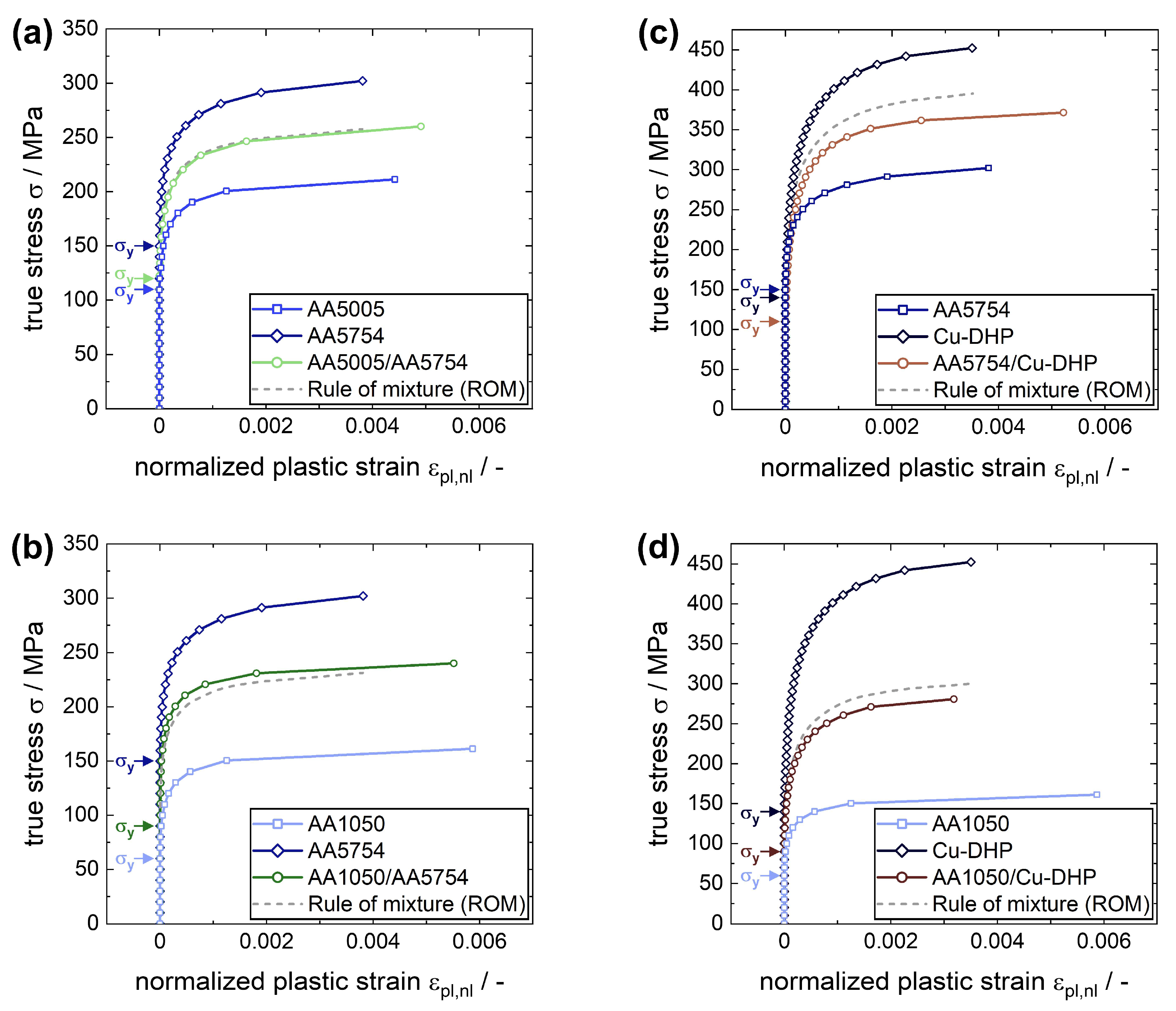
The overview provided in Figure 5 is showing the continuous stress–strain curves derived from the cyclic tensile LUR tests and summarizes the results of the mechanical behavior and properties of the metallic laminate systems and their monolithic constituents in the microyielding regime.
As a point of reference for the stress–strain behavior of the laminates, a linear rule of mixture (ROM) has been calculated based on the monolithic constituents and their respective volume fraction in the metallic laminates. As discussed in the sections above, the behavior at the onset of plasticity in metallic laminates cannot be adequately described by a rule of mixture. Instead, a weakest link concept complemented by considerations regarding stress redistribution, if applicable, would be better suited in this case. For higher plastic strains, differences between the experimental data and stress–strain-behavior calculated based on the ROM concept can be caused by several different effects, including statistical effects, morphology of the interface or influences of the interface-affected zone.

3.2. Evaluation of Inelastic Back Strain (IBS) in Metallic Laminates

Substantial non-linear elastic behavior has been observed in Figure 4 upon unloading, leading to inelastic back strain. In monolithic materials, this phenomenon can be explained by the microscopic forward/back flow of geometrically necessary dislocations piled up at the grain boundaries during the unloading/reloading segments [3,25,26,28]. As can be seen in Figure 4a–c, the characteristics of non-linear elastic unloading/reloading behavior and the associated inelastic back strain decreases with increasing Mg content in AA5005 and AA5754 aluminum alloys compared to the technically pure aluminum AA1050. Since magnesium atoms are primarily dissolved in the aluminum crystal lattice [35], they inhibit dislocation movement, thereby reducing the inelastic back strain upon unloading. The cyclic LUR curves of the metallic laminates shown in Figure 4 exhibit different degrees of inelastic back strain (IBS) depending on the laminate system.
Providing a concise way to analyze the evolution of inelastic back strain for metallic laminates, the inelastic back strain was determined for every unloading cycle and plotted in Figure 6 as a function of the maximum normalized plastic strain εpl, nl obtained upon unloading. In addition, the inelastic back strain of the monolithic constituents was included for each metallic laminate system. Furthermore, a linear rule of mixture behavior (ROM) was calculated to serve as a point of reference for the laminate systems.
As shown in Figure 6a–d, the evolution of inelastic back strain with increasing plastic strain exceeds the reference behavior provided by the ROM approximation in all laminate systems. For the AA5005/AA5754 system with a comparatively low yield strength ratio YR of 1.3 (Figure 6a), the amount of inelastic back strain is marginally higher than the ROM behavior. A similar trend can be observed for the AA1050/AA5754 laminate system with a comparatively high yield strength ratio YR of 2.3 (Figure 6b) where the deviation between the inelastic back strain of the composite and the ROM behavior is higher compared to the AA5005/AA5754 system. Furthermore, at elevated microplastic strains of 0.002 and above, the inelastic back strain of the laminate reaches the same level as the softer monolithic constituent (AA1050) and subsequently surpasses the inelastic strain behavior of the monolithic constituents at high strains. For both Al/Cu-laminate systems, the inelastic back strains determined for the laminates exceed the values determined for the respective monolithic constituents. This can be observed starting at small plastic strains of about 0.0005 for the AA5754/Cu-DHP laminate with an elastic modulus ratio ER of 1.9 (Figure 6c) and about 0.001 for the AA1050/Cu-DHP laminate with a combined elastic modulus and yield strength ratio ER + YR of 2.0 and 2.3 (Figure 6d), respectively.
For all metallic laminate systems discussed above, the inelastic back strain exceeds the reference behavior of the ROM approximation. Furthermore, the deviation increases with accumulating plastic strain. Consequently, additional effects complementing the forward/backward flow of dislocations piled up at the grain boundaries must be present in metallic laminates compared to monolithic materials. These effects are caused by the heterogeneous co-deformation near the interfaces in metallic laminates with dissimilar mechanical properties and thus are responsible for the increased inelastic back strain in metallic laminates compared to the rule of mixture reference behavior.
Figure 6e highlights the influence of the interface density ρIF on the evolution of inelastic back strain in two Cu/Fe-laminate systems with comparable processing histories.
Starting at low microplastic strains of about 0.0005, the inelastic back strain of the Cu-OFE/DC05 N8 laminate system with a higher nominal interface density of about 3280 mm−1 surpasses the inelastic back strain of the Cu-OFE/DC05 N4 laminate system with a lower nominal interface density of about 40 mm−1 and the difference increases further with accumulating microplastic strain. As both the deformation behavior and mechanical properties of the monolithic constituents are dissimilar, albeit not determined experimentally in this study, emerging heterogeneous co-deformation effects at the vicinity of interfaces in both laminates are apparent. As the interface density is significantly higher for the N8 laminate and thus interface-related effects play a more elaborate role, an increase in inelastic back strain for the N8 laminate compared to N4 is connected to the dimension of co-deformation effects. Thus, the experimental determination of inelastic back strain can be used to evaluate and quantify co-deformation effects in metallic laminates.

3.3. Evaluation of the Residual Plastic Strain Distribution in Metallic Laminates

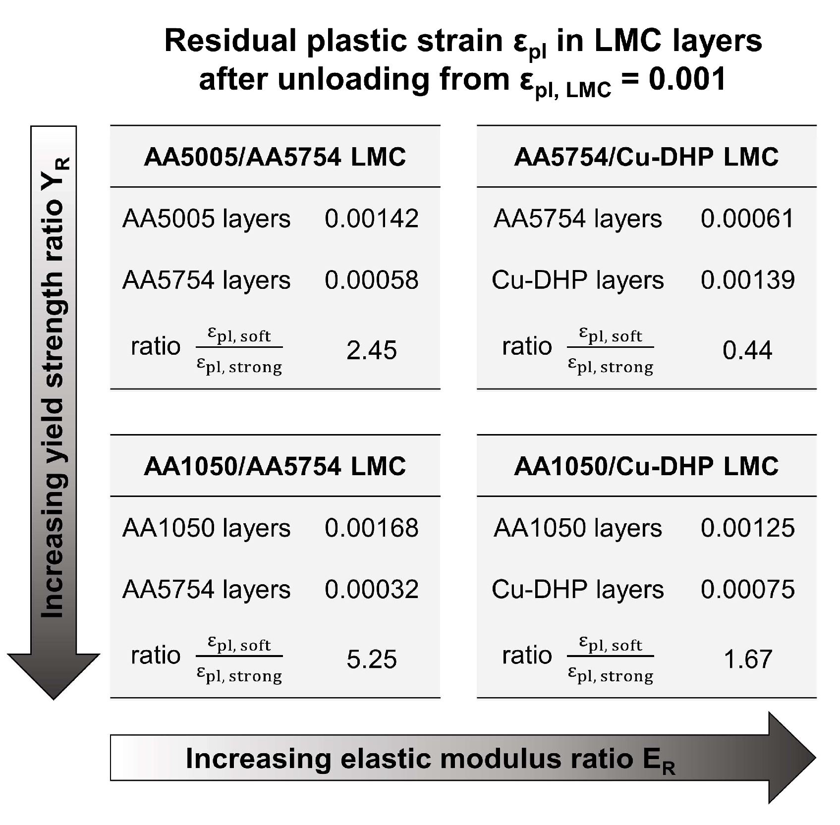
When subjecting heterogeneous metallic laminates to (cyclic) tensile loadings, the resulting formation of residual stress and plastic strain is distributed unevenly in the individual layers due to the dissimilarities in the mechanical properties of the constituents. Consequently, in the microyielding regime, the plastic deformation determined for the laminate composite is locally distributed unevenly among the layers of different constituents. The distribution of residual plastic strain upon unloading in the respective layers of the different metallic laminate systems presented in this study was assessed by conducting finite element analysis (FEA). Figure 7 gives an overview of the residual plastic strain εpl distributions determined by FE analysis upon unloading at εpl, LMC = 0.001 for the different heterogeneous metallic laminates investigated in this study.
As can be seen in Figure 7 (top left and bottom left), the plastic deformation is primarily concentrated in the softer layers for both heterogeneous Al/Al-laminates. As the ratio YR of the constituent’s (micro) yield strength increases, the distribution of residual plastic strain is continuously shifted towards the softer layers. This is expressed by the ratio of residual plastic strain provided in Figure 7: the amount of plastic strain exhibited by the softer layer is about 2.5 times (5.25 times) higher than the plastic strain exhibited by the stronger layer for the Al/Al-laminate system with the smaller (larger) yield strength ratio YR. In the case of the Al/Cu-laminates (see Figure 7, top right and bottom right), the plastic strain is distributed more evenly across layers of different constituents. This is caused by stress shielding of the Al layers resulting from the dissimilar elastic moduli of aluminum and copper constituents. The effect is highlighted by comparing the residual plastic strain distributions in metallic laminate systems with similar ratios YR of the constituent’s micro yield strength, as shown in Figure 7 (bottom left and right). Additionally, the stress shielding effect leads to plastic deformation being primarily concentrated in the stiffer copper layers for the AA5754/Cu-DHP composite (Figure 7, top right) with similar micro yield strength σY of constituents (YR = 1).

4. Discussion

In heterogeneous metallic laminates, the dissimilar deformation behavior of the layers (during processing of the laminates or subsequent mechanical loading) needs to be compensated by additional local plastic deformation near the interfaces. These locally confined, additional straining effects can be called co-deformation effects. As a result of the necessary co-deformation at the vicinity of interfaces, a complex interface dislocation network depending on the different strain gradients caused by the local change of the mechanical properties across the layer interface is formed by the pile-up of geometrically necessary dislocations, creating the so-called hetero-deformation zone. The strain gradient defining the hetero-deformation zone decreases with an increasing distance to the interface and can be described by a reciprocal function [1,2]. Both the range and the magnitude of the strain gradient scale with the amount of plastic strain accumulated during (cyclic) deformation. The spatial distribution of the strain gradient in the layers adjacent to the interfaces depends on the distribution of plastic flow in these layers upon loading and can thus be estimated using the results of the finite element analysis (see Figure 7).
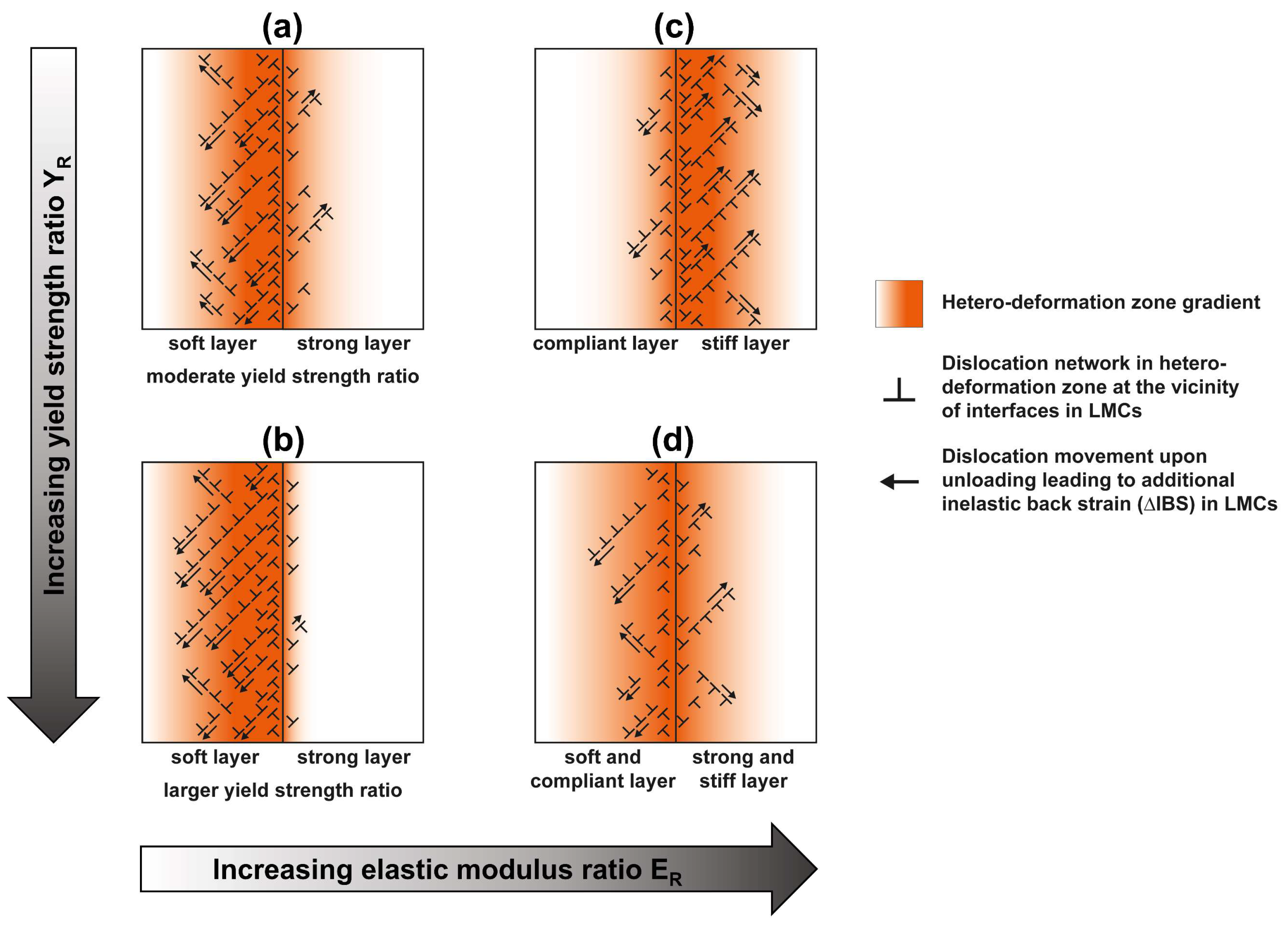
Based on these considerations, a schematic overview of the gradient and the distribution of the interface dislocation network defining the hetero-deformation zones at the vicinity of interfaces is given in Figure 8 for metallic laminate systems with dissimilar yield strength and/or elastic moduli of constituents.
The interface dislocation network is primarily concentrated in the layers exhibiting the larger amount of plastic deformation. These are the softer layers for metallic laminates with dissimilar yield strength (Figure 8a,b) and the stiffer layers for metallic laminates with dissimilar elastic moduli (Figure 8c). For metallic laminates with both dissimilar yield strength and elastic moduli (Figure 8d), the hetero-deformation zone is active in both layers adjacent to the interface.
As described in the section above, the dislocation networks at the vicinity of interfaces are formed upon tensile loading of the heterogeneous metallic laminates to compensate for the co-deformation behavior of the layers with dissimilar mechanical properties. This co-deformation generates a stress gradient, hence causing a forward flow of dislocations into the hetero-deformation zone and subsequently a pile-up of dislocations at the interfaces [3]. Upon unloading, the stress gradient is inverted, causing a back flow of the piled-up interface dislocations. This effect creates an additional amount of inelastic back strain ∆IBS for metallic laminates. Consequently, the amount of additional inelastic back strain ∆IBS can be interpreted as a quantitative measure of the co-deformation effects appearing in the hetero-deformation zones in metallic laminates subjected to cyclic tensile loading.
The additional inelastic back strain ∆IBS in heterogeneous metallic laminates can be determined experimentally from the total amount of inelastic back strain (IBS) measured by cyclic loading/unloading/reloading (LUR) tensile tests. This is based on the following considerations: As discussed in Section 3.2, the inelastic back strain determined experimentally for all metallic laminate systems exceeds the reference behavior, calculated as a linear rule of mixture approximation (ROM). Furthermore, the difference increases with accumulating plastic strain. The rule of mixture approximation describes the behavior of the individual constituents of the metallic laminates upon unloading, where inelastic back strain is caused exclusively by the forward/back flow of dislocations piled up at grain boundaries. Consequently, the increased inelastic back strain in metallic laminates compared to the rule of mixture behavior is caused by the additional forward/back flow of the geometrically necessary dislocations in the hetero-deformation zone piled up at the interface. At a given microplastic strain εpl, nl, the additional inelastic back strain ∆IBS in metallic laminates can be calculated as follows:
Δ I B S = I B S L M C I B S R O M
with IBSLMC being the inelastic back strain determined experimentally for a laminated metal composite and IBSROM being the inelastic back strain calculated by a linear rule of mixture approximation based on the respective monolithic constituents.
Table 3 gives an overview of the respective inelastic back strain ∆IBS, IBSLMC, and IBSROM determined for all metallic laminate systems in this study at low and high microplastic strain εpl, nl of 0.001 and 0.005, respectively.
Both for high and low microplastic strains, the magnitude of co-deformation effects varies significantly depending on the laminate systems (see Table 3). The evolution of the additional inelastic back strain ∆IBS quantifying co-deformation effects in metallic laminates is summarized in Figure 9 as a function of the accumulated microplastic strain for all laminate systems investigated in this study. For heterogeneous Al/Al-laminate systems, an increased yield strength ratio YR of constituents leads to larger co-deformation effects at the vicinity of interfaces upon cyclic loading. These effects are continuously increasing for higher microplastic strains. Compared to heterogeneous Al/Al-laminate systems with dissimilar yield strength (YR), the softer Al layers are shielded due to the higher elastic modulus of copper layers in Al/Cu-laminates with dissimilar yield strength. Consequently, the hetero-deformation zone is distributed more evenly in both layers adjacent to interfaces (see Figure 7 and Figure 8). As evident from Figure 9a, this leads to an increased amount of co-deformation measured for the Al/Cu-laminates compared to heterogeneous Al/Al-laminate systems. The largest amount of co-deformation was determined for Al/Cu-laminates with dissimilar elastic moduli (ER) and similar yield strength (Figure 9a), where the hetero-deformation zone is primarily concentrated in the stiffer copper layers (see Figure 7 and Figure 8) as an effect of stress shielding.
Figure 9b shows the effect of the interface density σIF on the additional inelastic back strain in metallic laminates schematically. A quantitative evaluation of ∆IBS according to Equation (4) was not realized for the Cu/Fe-laminates with different interface densities since the monolithic materials were not processed. Thus, the axes in Figure 9b do not include units or scales, and the effect of the interface density on ∆IBS is discussed solely in a qualitative manner. For metallic laminates with low interface density, the size of the hetero-deformation zone is small compared to the layer thickness. Consequently, the deformation behavior is primarily dominated by the bulk deformation behavior of the layers, leading to lower amounts of additional inelastic back strain ∆IBS measured for metallic laminates with low interface density. For metallic laminates with high interface density, the size of the hetero-deformation zone is significant compared to the layer thickness, and the hetero-deformation zones of adjacent interfaces may even overlap. Thus, the deformation behavior is primarily dominated by characteristics of the co-deformation behavior in the hetero-deformation zone, leading to high amounts of additional inelastic back strain ∆IBS measured for metallic laminates with high interface density.

5. Conclusions

Determining the inelastic back strain (IBS) by means of cyclic loading–unloading–reloading (LUR) tensile tests provides a feasible experimental method to quantify co-deformation effects in metallic laminates. The influences of the yield strength ratio (YR), the elastic modulus ratio (ER) and the interface density (ρIF) on the co-deformation behavior have been studied systematically. The following conclusions can be drawn:
  • Additional amounts of inelastic back strain (∆IBS) were determined upon unloading for all laminate systems compared to linear rule of mixture (ROM) references based on their respective monolithic materials. This is caused by the back flow of dislocations piled up at the interfaces to compensate for the necessary co-deformation of adjacent layers, forming the so-called hetero-deformation zone.
  • The ∆IBS was found to be increased for higher yield strength ratios (YR) between constituents in metallic laminates. FEA analysis shows that the plastic deformation is concentrated primarily in the softer layer and the localization increases for higher YR. These findings indicate that the hetero-deformation zone is concentrated primarily in the near interface regions of the softer layers in heterogeneous Al/Al-laminates.
  • The ∆IBS was measured to be increased further for metallic laminates exhibiting a difference in elastic moduli of constituents (ratio ER). This results from a more complex co-deformation behavior at the vicinity of interfaces due to additional stress shielding of the compliant layer upon loading. As shown by FEA analysis, the plastic strain is concentrated predominantly in the stiffer layers for metallic laminates with increasing ER, whereas the plastic strain is distributed more evenly among both constituents for laminates with YR + ER. These conclusions can be transferred to the spatial distribution of the hetero-deformation zone in Al/Cu-laminates.
  • Increasing the interface density ρIF in metallic laminates leads to significantly higher ∆IBS. While the size of the hetero-deformation zone at the interfaces stays constant, the layer thickness is significantly reduced in laminate systems with high ρIF as these two properties are connected inversely. In this case, the deformation behavior of the layers is influenced increasingly by the characteristics of the hetero-deformation zone. Consequently, co-deformation effects are significantly pronounced for metallic laminates with high ρIF compared to laminate systems with low ρIF.

Author Contributions

Conceptualization, P.M.P. and H.W.H.; methodology, P.M.P., M.K. and H.W.H.; software, M.K.; validation, M.G. and H.W.H.; investigation, P.M.P. and M.K.; resources, M.G.; data curation, P.M.P.; writing—original draft preparation, P.M.P.; writing—review and editing, P.M.P., M.K., M.G. and H.W.H.; visualization, P.M.P.; supervision, M.G. and H.W.H.; project administration, H.W.H.; funding acquisition, H.W.H. All authors have read and agreed to the published version of the manuscript.

Funding

This research was funded by the German Research Foundation (DFG) within the framework of research project 492276977.

Data Availability Statement

Not applicable.

Acknowledgments

The authors gratefully acknowledge the partial funding provided by the German Research Foundation (DFG). We also acknowledge financial support by Deutsche Forschungsgemeinschaft and Friedrich-Alexander-Universität Erlangen-Nürnberg within the funding programme “Open Access Publication Funding”. The authors are very grateful for the support provided by Antonia Gerschütz and Alexander Rieschl in the production of the metallic laminates and for conducting individual experiments.

Conflicts of Interest

The authors declare no conflict of interest.

References

  1. Zhu, Y.; Wu, X. Heterostructured materials. Prog. Mater. Sci. 2023, 131, 101019. [Google Scholar] [CrossRef]
  2. Zhu, Y. Introduction to Heterostructured Materials: A Fast Emerging Field. Metall. Mater. Trans. A 2021, 52, 4715–4726. [Google Scholar] [CrossRef]
  3. Zhu, Y.; Ameyama, K.; Anderson, P.M.; Beyerlein, I.J.; Gao, H.; Kim, H.S.; Lavernia, E.; Mathaudhu, S.; Mughrabi, H.; Ritchie, R.O.; et al. Heterostructured materials: Superior properties from hetero-zone interaction. Mater. Res. Lett. 2021, 9, 1–31. [Google Scholar] [CrossRef]
  4. Misra, A.; Göken, M.; Mara, N.A.; Beyerlein, I.J. Hierarchical and heterogeneous multiphase metallic nanomaterials and laminates. MRS Bull. 2021, 46, 236–243. [Google Scholar] [CrossRef]
  5. Kümmel, F.; Diepold, B.; Sauer, K.F.; Schunk, C.; Prakash, A.; Höppel, H.W.; Göken, M. High Lightweight Potential of Ultrafine-Grained Aluminum/Steel Laminated Metal Composites Produced by Accumulative Roll Bonding. Adv. Eng. Mater. 2019, 21, 1800286. [Google Scholar] [CrossRef]
  6. Embury, D.; Bouaziz, O. Steel-Based Composites: Driving Forces and Classifications. Annu. Rev. Mater. Res. 2010, 40, 213–241. [Google Scholar] [CrossRef]
  7. Ma, E.; Zhu, T. Towards strength–ductility synergy through the design of heterogeneous nanostructures in metals. Mater. Today 2017, 20, 323–331. [Google Scholar] [CrossRef]
  8. Li, X.; Lou, L.; Song, W.; Huang, G.; Hou, F.; Zhang, Q.; Zhang, H.-T.; Xiao, J.; Wen, B.; Zhang, X. Novel Bimorphological Anisotropic Bulk Nanocomposite Materials with High Energy Products. Adv. Mater. 2017, 29, 1606430. [Google Scholar] [CrossRef]
  9. Huang, G.; Li, X.; Lou, L.; Hua, Y.; Zhu, G.; Li, M.; Zhang, H.-T.; Xiao, J.; Wen, B.; Yue, M.; et al. Engineering Bulk, Layered, Multicomponent Nanostructures with High Energy Density. Small 2018, 14, 1800619. [Google Scholar] [CrossRef]
  10. Sawangrat, C.; Kato, S.; Orlov, D.; Ameyama, K. Harmonic-structured copper: Performance and proof of fabrication concept based on severe plastic deformation of powders. J. Mater. Sci. 2014, 49, 6579–6585. [Google Scholar] [CrossRef]
  11. Ameyama, K.; Cazes, F.; Couque, H.; Dirras, G.; Kikuchi, S.; Li, J.; Mompiou, F.; Mondal, K.; Orlov, D.; Sharma, B.; et al. Harmonic structure, a promising microstructure design. Mater. Res. Lett. 2022, 10, 440–471. [Google Scholar] [CrossRef]
  12. Park, H.K.; Kim, Y.; Jung, J.; Lee, H.H.; Park, J.M.; Ameyama, K.; Kim, H.S. Efficient design of harmonic structure using an integrated hetero-deformation induced hardening model and machine learning algorithm. Acta Mater. 2023, 244, 118583. [Google Scholar] [CrossRef]
  13. Lu, K. Making strong nanomaterials ductile with gradients. Science 2014, 345, 1455–1456. [Google Scholar] [CrossRef] [PubMed]
  14. Fang, T.H.; Li, W.L.; Tao, N.R.; Lu, K. Revealing Extraordinary Intrinsic Tensile Plasticity in Gradient Nano-Grained Copper. Science 2011, 331, 1587–1590. [Google Scholar] [CrossRef]
  15. Höppel, H.W.; Westermeyer, M.; Kümmel, F.; Göken, M. The Role of Interfaces on the Deformation Mechanisms in Bimodal Al Laminates Produced by Accumulative Roll Bonding. Adv. Eng. Mater. 2020, 22, 2000145. [Google Scholar] [CrossRef]
  16. Wang, Y.; Chen, M.; Zhou, F.; Ma, E. High tensile ductility in a nanostructured metal. Nature 2002, 419, 912–915. [Google Scholar] [CrossRef]
  17. Pohl, P.M.; Kümmel, F.; Schunk, C.; Serrano-Munoz, I.; Markötter, H.; Göken, M.; Höppel, H.W. About the Role of Interfaces on the Fatigue Crack Propagation in Laminated Metallic Composites. Materials 2021, 14, 2564. [Google Scholar] [CrossRef]
  18. Ma, X.; Huang, C.; Moering, J.; Ruppert, M.; Höppel, H.W.; Göken, M.; Narayan, J.; Zhu, Y. Mechanical properties of copper/bronze laminates: Role of interfaces. Acta Mater. 2016, 116, 43–52. [Google Scholar] [CrossRef]
  19. Beyerlein, I.J.; Mara, N.A.; Carpenter, J.S.; Nizolek, T.; Mook, W.M.; Wynn, T.A.; McCabe, R.J.; Mayeur, J.R.; Kang, K.; Zheng, S.; et al. Interface-driven microstructure development and ultra high strength of bulk nanostructured Cu-Nb multilayers fabricated by severe plastic deformation. J. Mater. Res. 2013, 28, 1799–1812. [Google Scholar] [CrossRef]
  20. Skelton, R.P.; Maier, H.J.; Christ, H.-J. The Bauschinger effect, Masing model and the Ramberg–Osgood relation for cyclic deformation in metals. Mater. Sci. Eng. A 1997, 238, 377–390. [Google Scholar] [CrossRef]
  21. Zhu, Y.; Wu, X. Perspective on hetero-deformation induced (HDI) hardening and back stress. Mater. Res. Lett. 2019, 7, 393–398. [Google Scholar] [CrossRef]
  22. Huang, C.X.; Wang, Y.F.; Ma, X.L.; Yin, S.; Höppel, H.W.; Göken, M.; Wu, X.L.; Gao, H.J.; Zhu, Y.T. Interface affected zone for optimal strength and ductility in heterogeneous laminate. Mater. Today 2018, 21, 713–719. [Google Scholar] [CrossRef]
  23. Yang, M.; Pan, Y.; Yuan, F.; Zhu, Y.; Wu, X. Back stress strengthening and strain hardening in gradient structure. Mater. Res. Lett. 2016, 4, 145–151. [Google Scholar] [CrossRef]
  24. Jiang, S.; Lin Peng, R.; Zhao, X.; Zuo, L.; Jia, N. Deformation incompatibility enables hetero-deformation induced strengthening in Ti/Nb laminates. Mater. Res. Lett. 2023, 11, 126–133. [Google Scholar] [CrossRef]
  25. Mughrabi, H.; Höppel, H.W.; Kautz, M. Fatigue and microstructure of ultrafine-grained metals produced by severe plastic deformation. Scr. Mater. 2004, 51, 807–812. [Google Scholar] [CrossRef]
  26. Mughrabi, H.; Höppel, H.W.; Kautz, M.; Valiev, R.Z. Annealing treatments to enhance thermal and mechanical stability of ultrafine-grained metals produced by severe plastic deformation. Z. Met. 2003, 94, 1079–1083. [Google Scholar] [CrossRef]
  27. Höppel, H.W.; Xu, C.; Kautz, M.; Barta-Schreiber, N.; Langdon, T.G.; Mughrabi, H. Cyclic Deformation Behaviour and Possibilities for Enhancing the Fatigue Properties of Ultrafine-Grained Metals. In Nanomaterials by Severe Plastic Deformation; Wiley-VCH Verlag GmbH & Co. KGaA: Baden, Germany, 2005; pp. 677–683. [Google Scholar]
  28. Li, L.; Van Petegem, S.; Van Swygenhoven, H.; Anderson, P.M. Slip-induced intergranular stress redistribution in nanocrystalline Ni. Acta Mater. 2012, 60, 7001–7010. [Google Scholar] [CrossRef]
  29. Wang, Y.F.; Huang, C.X.; Fang, X.T.; Höppel, H.W.; Göken, M.; Zhu, Y.T. Hetero-deformation induced (HDI) hardening does not increase linearly with strain gradient. Scr. Mater. 2020, 174, 19–23. [Google Scholar] [CrossRef]
  30. Kittel, C. Introduction to Solid State Physics, 8th ed.; John Wiley & Sons, Inc.: Hoboken, NJ, USA, 2005; ISBN 047141526X. [Google Scholar]
  31. Sommer, C.; Christ, H.-J.; Mughrabi, H. Non-linear elastic behaviour of the roller bearing steel SAE 52100 during cyclic loading. Acta Metall. Mater. 1991, 39, 1177–1187. [Google Scholar] [CrossRef]
  32. Schunk, C.; Nitschky, M.; Höppel, H.W.; Göken, M. Superior Mechanical Properties of Aluminum-Titanium Laminates in Terms of Local Hardness and Strength. Adv. Eng. Mater. 2019, 21, 1800546. [Google Scholar] [CrossRef]
  33. Hoppel, H.W.; Zhou, Z.M.; Mughrabi, H.; Valiev, R.Z. Microstructural study of the parameters governing coarsening and cyclic softening in fatigued ultrafinegrained copper. Philos. Mag. A Phys. Condens. Matter Struct. Defects Mech. Prop. 2002, 82, 1781–1794. [Google Scholar] [CrossRef]
  34. Wang, J.T.; Zhang, Y.; Liu, J.Q. Continuous Recrystallization Phenomenon in High Purity Copper during Equal Channel Angular Pressing up to High Strain at Room Temperature. Mater. Sci. Forum 2008, 584–586, 929–937. [Google Scholar] [CrossRef]
  35. Ryen, Ø.; Holmedal, B.; Nijs, O.; Nes, E.; Sjölander, E.; Ekström, H.-E. Strengthening mechanisms in solid solution aluminum alloys. Metall. Mater. Trans. A 2006, 37, 1999–2006. [Google Scholar] [CrossRef]
Figure 1. Overview of the materials analyzed in this study: (a) Light microscope images showing cross-sections of the metallic laminate systems with dissimilar mechanical properties between layers: varying yield strength characterized by the yield strength ratio YR (top to bottom) and varying elastic modulus characterized by the elastic modulus ratio ER (left to right) between layers; (b) Scanning electron microscope images showing cross-sections of the copper/steel laminates with varying interface density ρIF.
Metals 13 01049 g001
Figure 2. Non–linear elastic behavior: (a) Potential energy as a function of the interatomic spacing (top) and the derived approximations describing linear–elastic and non–linear elastic behavior (bottom), adapted from [31] with permission; (b) Connection of the stress-dependent differential modulus ED(σ) and the stress independent elastic modulus E0; (c) Cyclic loading–unloading–reloading (LUR) tensile test (plot of true stress versus plastic strain) with and without including the correction for non-linear elastic behavior. Determination of inelastic back strain (IBS) upon unloading; (d) Continuous stress–strain curve derived from the cyclic LUR tensile experiments and determination of the micro yield strength σY.
Metals 13 01049 g002
Figure 3. Determination of the residual plastic strain distribution in laminated metallic composites (LMCs) consisting of constituents with dissimilar mechanical properties using FE analysis: (a) Exemplary 2D model representing the cross-section of the tensile test specimen used in the cyclic LUR tests; (b) Loading of the FE model up to plastic strains of εpl, LMC = 0.001 for the laminated composites and subsequent unloading.
Metals 13 01049 g003
Figure 4. Microyielding stress–strain behavior (plot of true stress σ versus normalized true plastic strain εpl, nl) determined by cyclic loading–unloading–reloading (LUR) tensile tests: (ad) Monolithic materials AA1050, AA5005, AA5754 and Cu-DHP; (eh) Metallic laminate systems with varying yield strength ratio YR and elastic modulus ratio ER between layers; (i,j) Metallic laminate systems with varying interface density ρIF.
Metals 13 01049 g004
Figure 5. Continuous stress–strain curves derived from cyclic LUR tensile experiments and linear rule of mixture behavior (ROM) calculated for the laminated composites based on the volume fractions of the respective constituents: (a) AA5005/AA5754 laminate system (small yield strength ratio YR); (b) AA1050/AA5754 laminate system (large yield strength ratio YR); (c) AA5754/Cu-DHP laminate system (elastic modulus ratio ER); (d) AA1050/Cu-DHP laminate system (combined yield strength and elastic modulus ratio YR + ER).
Metals 13 01049 g005
Figure 6. Evolution of the inelastic back strain (IBS) upon unloading as a function of the residual plastic strain εpl, nl determined by cyclic LUR tensile tests. Calculation of a linear rule of mixture behavior (ROM) for the laminated composites based on the volume fractions of the respective constituents: (a) AA5005/AA5754 laminate system (small yield strength ratio YR); (b) AA1050/AA5754 laminate system (large yield strength ratio YR); (c) AA5754/Cu-DHP laminate system (elastic modulus ratio ER); (d) AA1050/Cu-DHP laminate system (combined yield strength and elastic modulus ratio YR + ER); (e) Cu-OFE/DC05 N4 and N8 laminate systems with low and high interface density ρIF, respectively.
Metals 13 01049 g006
Figure 7. Overview of the residual plastic strain εpl distribution determined by FE analysis within layers of different constituents in metallic laminates with dissimilar mechanical properties characterized by YR and ER.
Metals 13 01049 g007
Figure 8. Schematic illustrations of the hetero-deformation zones at the vicinity of interfaces in metallic laminates with dissimilar materials properties: (a) moderate YR; (b) large YR; (c) ER; (d) YR + ER. Formation of interface dislocation networks and pile-up of geometrically necessary dislocations at the interfaces compensating for the necessary co-deformation upon tensile loading of the laminated composites. Dislocation movement caused by back stress upon unloading leading to additional inelastic back strain (∆IBS) in metallic laminates depending on the distribution and gradient of the hetero-deformation zone in the layers adjacent to the interfaces.
Metals 13 01049 g008
Figure 9. Additional inelastic back strain ∆IBS as a quantitative measure for co-deformation effects in metallic laminates with dissimilar mechanical properties: (a) Influence of yield strength ratio (YR) and elastic modulus ratio (ER) of constituents on ∆IBS; (b) Influence of interface density ρIF on ∆IBS.
Metals 13 01049 g009
Table 1. Chemical composition (wt.%) of the aluminum, copper and steel sheet metal measured by spark emission spectrometry.
AlloyChemical Composition (wt.-%) 1
AlFeCuMgSiMnTiCPOthers
AA105099.40.35--0.15----0.10
AA500598.50.25-0.990.12----0.14
AA575495.90.40-2.910.350.31---0.13
Cu-DHP--99.92-----0.030.05
Cu-OFE--99.99------0.01
DC05-99.7---0.100.070.01-0.12
1 Elements with concentration below 0.05 wt.% listed as (-).
Table 2. Overview of mechanical properties (micro yield strength σY, yield strength σY0.2 and elastic modulus E) determined by cyclic LUR tensile tests. Calculation of yield strength ratio YR and elastic modulus ratio ER to characterize dissimilar mechanical properties between the respective constituents at the interfaces in the metallic laminate systems.
ARB-Processed Monolithic Materials & LMCsMechanical Properties
Micro Yield Strength σY/MPaYield Strength σY0.2/MPaElastic Modulus E/GPa(Micro) Yield Strength Ratio YR 1Elastic Modulus Ratio ER 1
AA10506315469--
AA500511020770--
AA575414729071--
Cu-DHP141433138--
AA5005/AA5754118256691.31.0
AA1050/AA575483233692.31.0
AA5754/Cu-DHP1093551111.01.9
AA1050/Cu-DHP852731022.32.0
Cu-OFE/DC05 N488516172 - 2 - 2
Cu-OFE/DC05 N859469171 - 2 - 2
1 Yield strength YR and elastic modulus ratio ER present at the interfaces of the respective laminates. Calculated based on the properties of the respective monolithic constituents of each laminate. 2 No monolithic constituent material produced.
Table 3. Additional inelastic back strain ∆IBS determined at low (εpl, nl = 0.001) and high (εpl, nl = 0.005) microplastic strain. ∆IBS calculated as the difference of inelastic back strain IBSLMC in laminates determined by cyclic LUR tensile tests and inelastic back strain IBSROM in laminates based on a linear rule of mixture behavior calculated from LUR tests of monolithic materials.
Laminated Metallic CompositesInelastic Back Strain IBS at εpl, nl = 0.001 and 0.005
IBSLMC × 104IBSROM × 104IBS × 104
0.0010.0050.0010.0050.0010.005
AA5005/AA57540.681.89 10.581.650.100.24
AA1050/AA57540.711.980.581.570.130.41
AA5754/Cu-DHP1.092.370.721.670.370.70
AA1050/Cu-DHP1.062.540.861.940.200.60
1 Extrapolated based on data shown in Figure 6a.
Disclaimer/Publisher’s Note: The statements, opinions and data contained in all publications are solely those of the individual author(s) and contributor(s) and not of MDPI and/or the editor(s). MDPI and/or the editor(s) disclaim responsibility for any injury to people or property resulting from any ideas, methods, instructions or products referred to in the content.