Article

Microstructure and Mechanical Properties of Friction Stir Welded DP1180 Steel Plates

1
School of Materials Science and Engineering, Zhengzhou University, Zhengzhou 450001, China
2
Division of R&D, Funik Ultrahard Material Co., Ltd., Zhengzhou 450001, China
3
Henan Key Laboratory of Advanced Magnesium Alloys, Zhengzhou University, Zhengzhou 450001, China
*
Authors to whom correspondence should be addressed.
Metals 2023, 13(7), 1164; https://doi.org/10.3390/met13071164
Submission received: 24 May 2023 / Revised: 15 June 2023 / Accepted: 20 June 2023 / Published: 22 June 2023
(This article belongs to the Special Issue Friction Stir Welding and Processing of Ferrous Alloys)

Abstract

:
The effect of rotation speeds from 100 to 600 rpm on the microstructure and mechanical properties of friction stir welded (FSW) DP1180 steel joints was studied. The microstructure in the different weld zones were examined using optical microscopy (OM), scanning electron microscopy (SEM), electron backscattering diffraction (EBSD), and transmission electron microscope (TEM). It was found that when welded at 100 rpm, there was an obvious boundary formed in the middle of the stir zone (SZ), which divided the SZ into two parts, namely, SZ-Ⅰ and SZ-Ⅱ. Significantly refined microstructures with an average grain size of 0.41 μm and 0.28 μm were observed in SZ-Ⅰ and SZ-Ⅱ, respectively. The SZs were mainly composed of martensite when the rotation speed increased over 200 rpm. The thermo-mechanically affected zone (TMAZ) of all joints was composed of martensite and ferrite. Microhardness tests showed that the minimum microhardness of heat affected zone (HAZ) of all joints was between 280–300 HV. It was revealed that as the rotation speed increased, the tensile strength of the joint decreased. The tensile strength of the 100 rpm joint was the highest, reaching 1094 MPa. The fracture position of the 100 rpm joint was in SZ while the fracture positions of the other joints were in HAZ.

1. Introduction

In recent years, advanced high strength duplex phase (DP) steel has been widely used in the automotive industry, which could ensure the structural safety of the car body and reduce the car weight. The microstructure of DP steel is composed of ductile ferrite and hard martensite. With the increase in martensite content from 5 to 30%, the strength of DP steel can increase from 450 to 1180 MPa accordingly [1,2]. The combined effects of ferrite and martensite results in DP steel exhibiting an excellent balance of strength, toughness, and processability [3].
DP steel is usually obtained by a thermal mechanical control process of low carbon and low alloy steels. The martensitic structure in DP steel is metastable and is sensitive to thermal when subjected to welding [2,3,4]. At present, steel materials are still mainly welded by fusional welding methods, during which solidification defects, high residual stress, coarse microstructure, and serious softening of HAZ are prone to occur [5,6]. Especially in the welding pool, the decomposition of moisture at a high temperature could cause the hydrogen to diffuse into the welded seam and result in hydrogen embrittlement of the steels [5]. With the increase in strength, the sharp decrease in the weldability of DP steel has become an obstacle to its further application in the automotive industry, and obtaining good welded joints has become a big challenge for DP steel [7]. Friction stir welding (FSW) is an advanced solid-state welding technology that was developed in TWI, UK, in 1991. Compared with fusional welding methods, the material does not melt in FSW. Therefore, the problems related with solidification could be avoided, and the FSW process is more energy-saving and environmentally friendly [8,9,10].
Although FSW has unique advantages over fusional welding methods, the research on the FSW of DP steel is still limited. Recently, S.M. Aktarer et al. [11] reported the friction stir processing (FSP) of a 1.5 mm thick DP600 steel plate. An ultra-fine microstructure with an average grain size less than 1 μm was formed in the stir zone (SZ). Compared with the base material (BM), the strength and microhardness of SZ were increased by a factor of 1.5, without sacrificing toughness. Mahdi. Mahmoudiniya et al. [12] studied the FSW of DP700 steel plates and found that as the microhardness of SZ increased, microhardness reduction and the width of the softened zone decreased when increasing the tool transverse speed. Therefore, the strength, elongation, and fracture toughness of the joint were improved. Xie. et al. [13] performed the friction stir spot welding (FSSW) of DP780 steel plates with a varied rotation rate from 500 to 1500 rpm. At rotation rates higher than 1000 rpm, a full martensitic structure was observed throughout the SZs. At the lower rotation rate of 500 rpm, the SZ consisted of a fine dual phase structure of ferrite and martensite. The highest failure load of 18.2 kN could be obtained for the joint welded at 1000 rpm. As the welding temperature was high and phase transformation occurred during the cooling periods, the microstructure in the final joints could be varied depending on the welding parameters. However, the FSW of DP steels without phase transformation could not be successfully obtained. Wang. et al. [14] conducted lap FSW on 1.35 mm thick DP1180 steel plates. The influence in heat input and material flow on the joint microstructural evolution, as well as the relationship between pin length and mechanical properties of the lap joint, were studied. However, many defects, such as cold lap, hook, and void defects were still found on the cross section of the joints, at which the failure of the joint began to generate during the tensile tests [15].
At present, there is relatively little research on the FSW of ultra-high strength DP steel, which severely limits its application in industry. In this study, the microstructure and mechanical properties of DP1180 steel FSW joints prepared at 100–600 rpm were studied. The aim of this study is to systematically analyze the effect of rotation speed on the microstructure and mechanical properties of DP1180 steel FSW joints.

2. Experimental Procedure

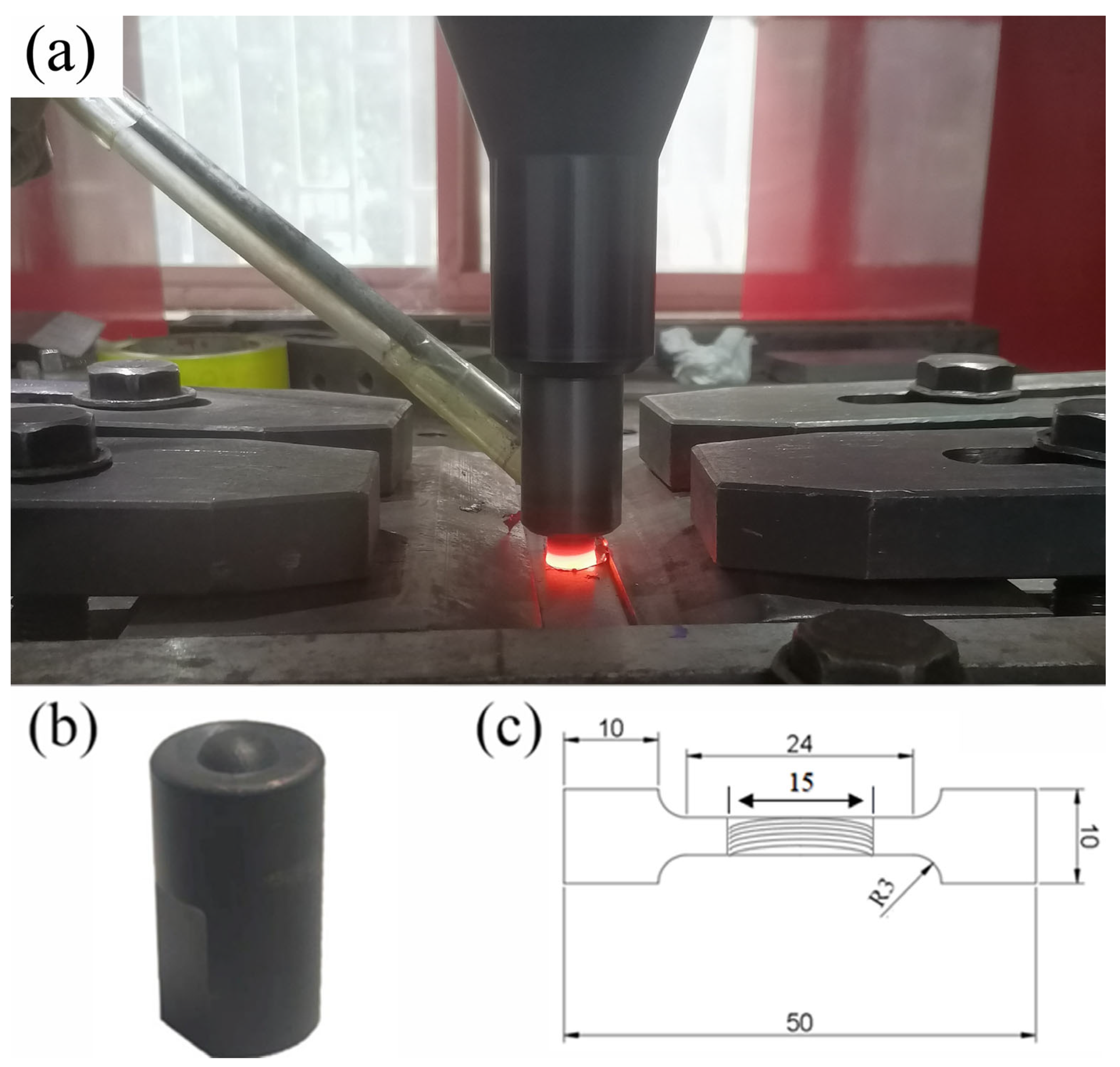
2.1. Material and Method

Commercial DP1180 steel plates with a size of 200 × 50 × 1.4 mm3 were used as BM in this study. The chemical composition was given in Table 1. In order to investigate the effect of heat input on the microstructure of joints, a gradually increasing rotation speed was used. The FSW were performed at different rotation speeds of 100, 200, 400, and 600 rpm and a fixed transverse speed of 100 mm/min. A pcBN rotating tool with a diameter of 15 mm, pin diameter of 6 mm, and pin length of 1.2 mm was used, as shown in Figure 1b. The rotating tool was inclined 2.5° to the steel plate’s normal direction and the tool become red during the FSW process, as shown in Figure 1a. Argon shielding gas with a flow rate of 30 L/min was used to prevent the weld seam and the tool from oxidation during welding.
The Ac1 and Ac3 phase transformation temperatures of steels can be calculated by the following formula [16]:
A c 1 = 723 10.7 Mn 16.9 Ni 29.1 Si 16.9 Cr + 290 As + 6.38 W
A c 3   ( ° C ) = 910 203 C 15.2 Ni + 44.7 Si + 31.5 Mo + 1.4 V + 13.1 W
Based on the above equations, the Ac1 and Ac3 of DP1180 were calculated to be 729 °C and 820 °C, respectively.

2.2. Microstructure Characterizations

The obtained joints were sectioned transversely with an electrical discharge wire cutter, and then etched with a 4% nital solution (4 mL HNO3 + 96 mL C2H5OH) after being ground and polished. Then, the microstructures of the etched specimens were characterized with an optical microscope (OM) and scanning electron microscope (SEM). For electron back-scatter diffraction (EBSD) measurement, the mechanically polished specimens were electropolished using a HClO4:CH3COOH = 1:9 solution at 20 V and 10 °C for 15 s. EBSD maps were measured with a step size of 100 nm. For transmission electron microscope (TEM) observation, thin film specimen transparent for electron beam were prepared by twin-jet electropolishing. Misorientations of 2° to 15° between neighboring grains were defined as low angle grain boundaries (LAGB), whereas misorientations over 15° were defined as high angle grain boundaries (HAGB).

2.3. Mechanical Properties

Vickers microhardness test with a load of 200 g and dwell time of 15 s were carried out on the polished cross-sectional plane of the joints. The microhardness distribution along the sectional plane of the joints was measured at an interval of 0.5 mm. Tensile specimen were wire cut transversely from the joints, and the dimension of the specimen is shown in Figure 1c. Tensile tests were carried out at a cross-head speed of 1 mm/min. For accuracy, at least three tensile specimens were tested for each joint.

3. Results and Discussion

3.1. The Surface Appearance of the Joints
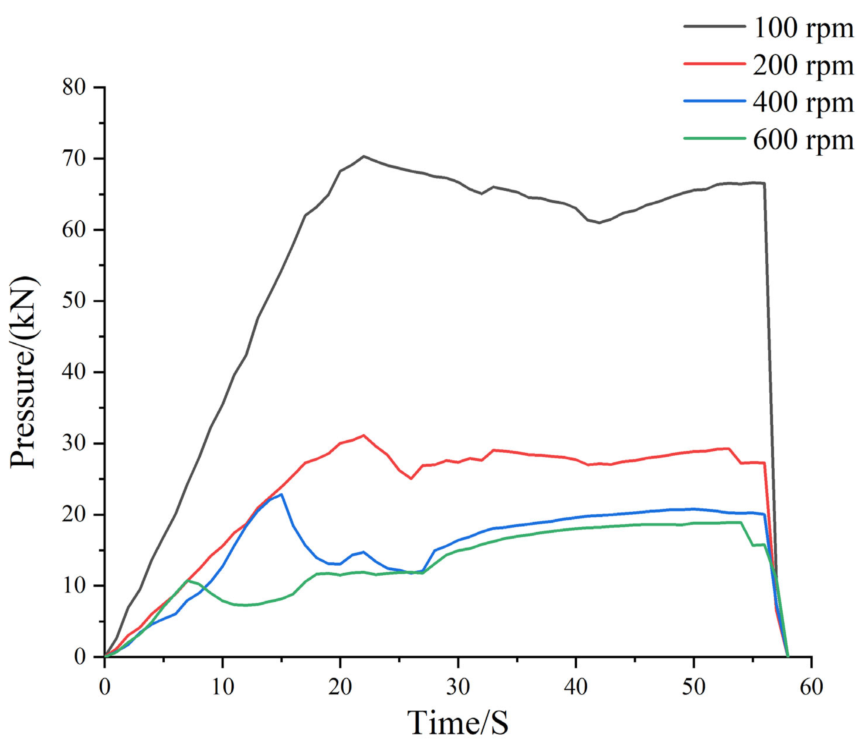
The joints without defects were obtained at various rotational speeds, as shown in Figure 2. With the increase in rotation speed, the revolutionary pitch (r), defined as the ratio of welding speed to rotation speed, decreased [17]. Under the protection of argon, there was no serious oxidation on the joints surface.

3.2. The Axis Force

According to the changes in the position of the rotating tool during the welding process, the entire welding process was divided into three stages: insertion stage, dwell stage, and welding stage, as shown in Figure 3. The maximum axial force of 100 rpm joint was 70.3 kN, which was much higher than the other joints. As the rotation speed increased, the maximum value of the axial force significantly decreased. When welded at 100 rpm and 200 rpm, the variation trend in the axial force was basically consistent. When the rotation speed exceeded 400 rpm, the axial force began to decrease before the dwell stage due to the large heat input.

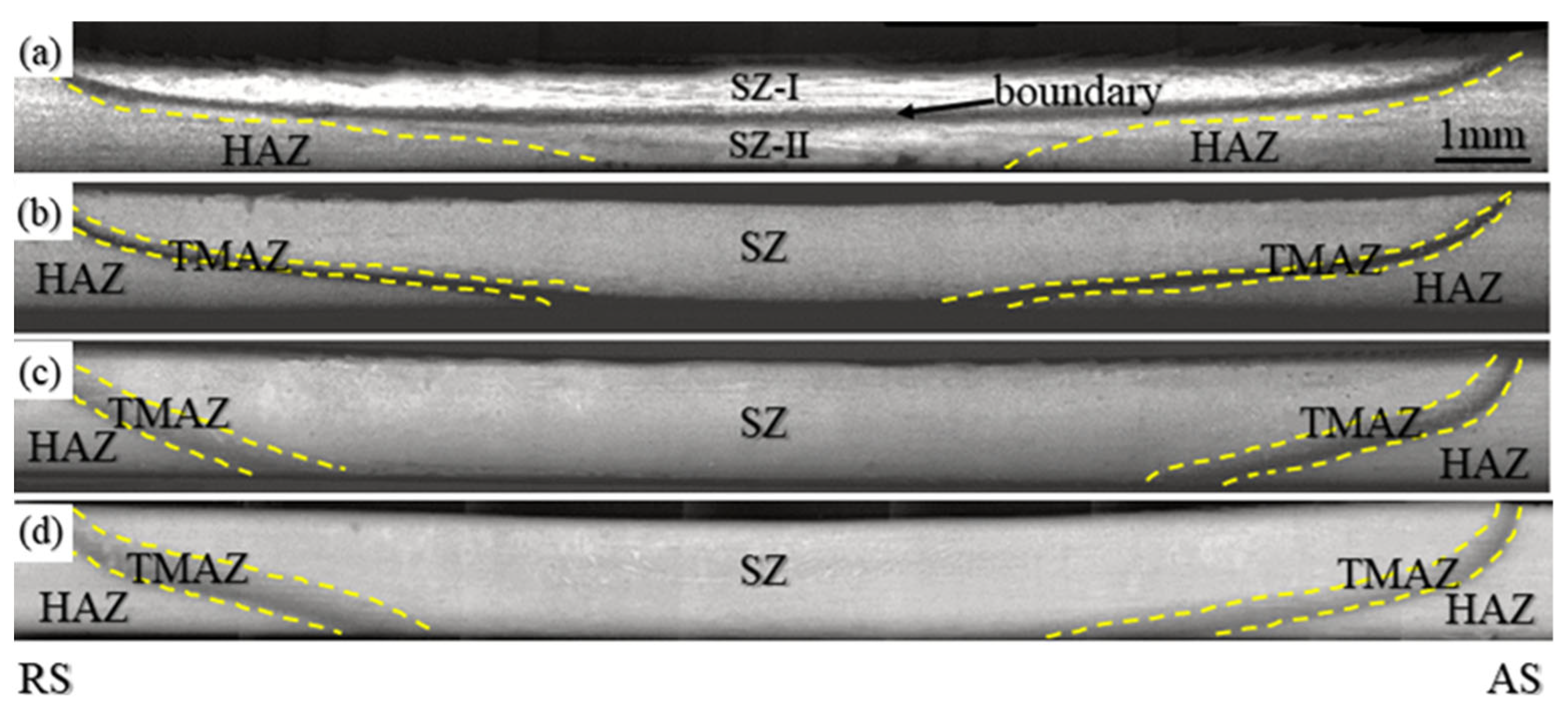
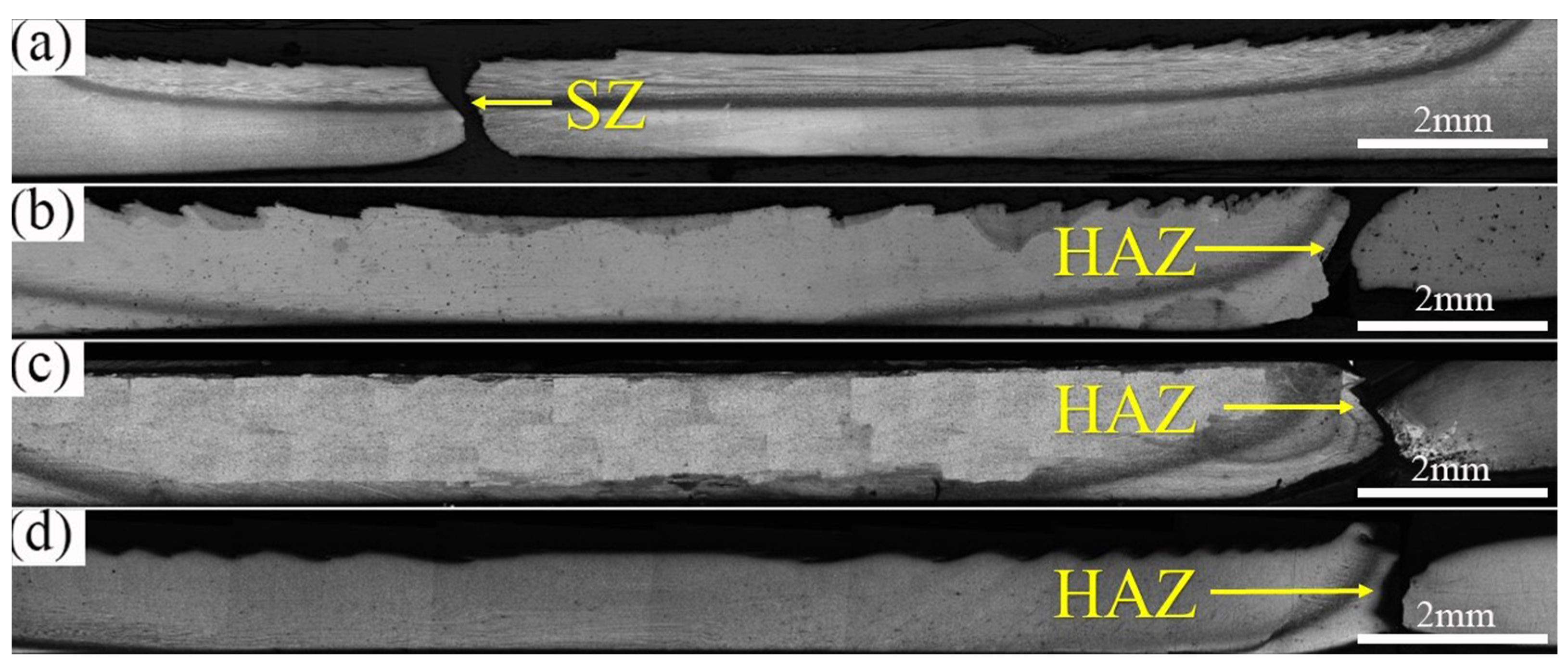
3.3. Macrographs of Joints

The OM macrographs of the cross-sectional plane of the joints are shown in Figure 4. The macrostructure of each joint can be generally divided into three different zones including SZ, TMAZ, and HAZ [18]. When welded at 200, 400, and 600 rpm, the SZ of the joints presented a typical bowl-like shape. It could also be observed that the width of SZ and TMAZ increased with the increase in rotation speed, which were attributed to the increase in heat input. However, an obvious black boundary in the nearly center SZ of the 100 rpm joint could be observed, which divided the SZ into two parts, namely, SZ-I and SZ-II. The black boundary in the center of SZ showed similar characteristics as the TMAZ of other joints. However, TMAZ usually appears in the edge area of SZ, while the black boundary formed along the central line of SZ. The thickness of the black boundary was measured to be 0.21 mm.

3.4. Microstructure

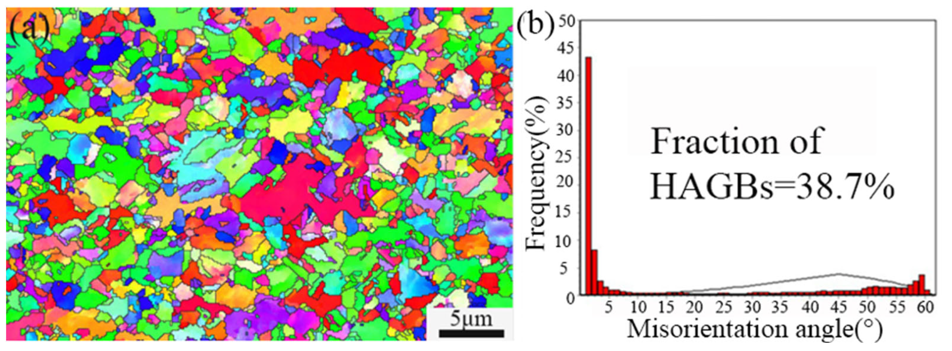
3.4.1. Base Material
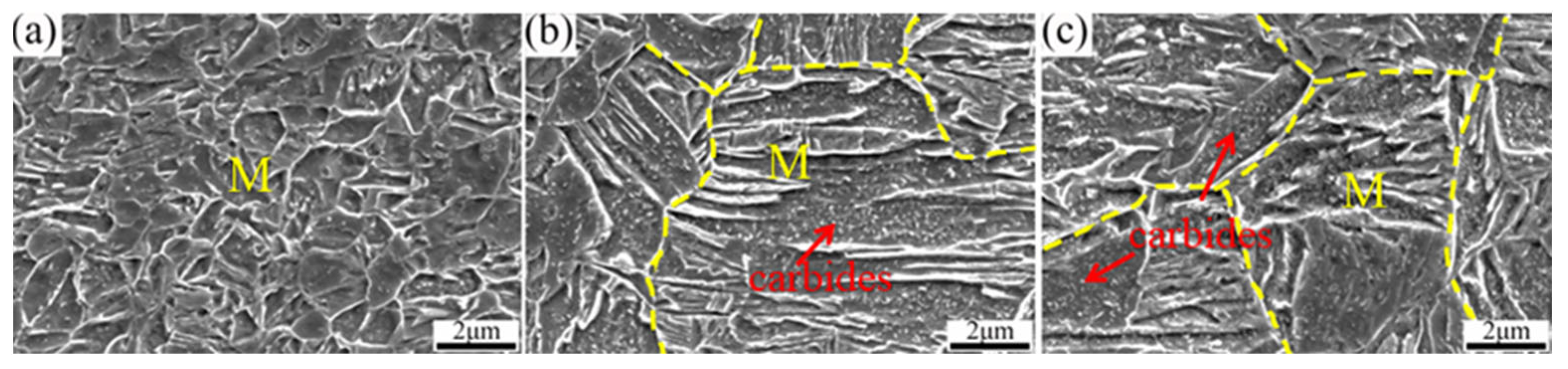
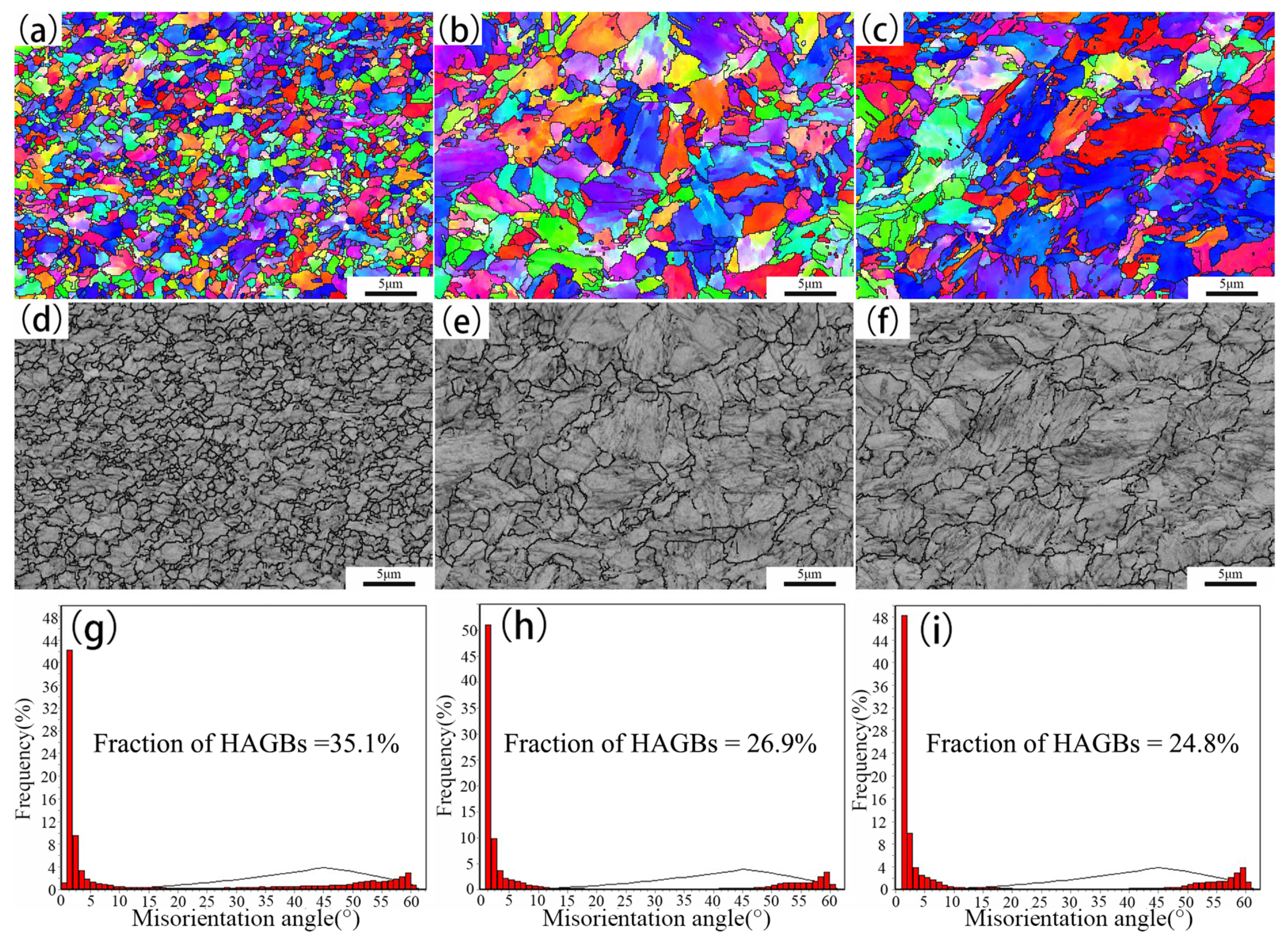
The microstructure of the BM is shown in Figure 5a, in which the indicated rectangle area is shown in Figure 5b. The BM of DP1180 consisted of uniformly distributed ferrite and martensite, in which ferrite accounted for 17.7% and martensite 82.3%. The ferrite showed an irregular shape and had an average grain size of about 2~5 μm.
Figure 6a shows the EBSD inverse pole figure (IPF) map of the BM and only the HAGB larger than 15° is indicated by the black line. Based on the EBSD measurement, the average grain size of BM was 3.8 μm. The misorientation distribution of BM is shown in Figure 6b, in which the HAGB fraction of the BM was about 38.7%.

3.4.2. Stir Zone

Figure 7 shows the microstructure of the FSW joint welded at 100 rpm; two obviously different ultra-fine microstructures were formed in both SZ-I and SZ-Ⅱ. As shown in Figure 7a, SZ-I was composed of fine martensite and ferrite, which indicated that the peak temperature of SZ-I was between Ac1 and Ac3. As shown in Figure 7c, the microstructure of SZ-Ⅱ was composed of ferrite and tempered martensite. In addition, a large amount of carbide precipitation was observed for SZ-Ⅱ, which indicated that the tempering of martensite occurred in SZ-Ⅱ during FSW. SZ-I was located at the top of the joint, which was mainly affected by the stirring of the tool shoulder during the welding process. The peak welding temperature of SZ-I should be the highest compared with other zones of the entire joint [19,20].
Figure 7b shows the microstructure of the black boundary between SZ-I and SZ-Ⅱ. The black boundary was mainly composed of elongated martensite parallel to the transverse direction and equiaxed ferrite grains. It was proposed that the black boundary was located at the junction of materials flow caused by the tool shoulder and the pin, respectively. During FSW, the peak temperature of the black boundary was between Ac1–Ac3; the microstructure was composed of austenite and ferrite. In addition, due to the different material flow rates of SZ-I and SZ-Ⅱ, the black boundary was squeezed [21]. Meanwhile, under the influence of a large axial load (at 100 rpm, the applied axial force in the vertical direction could reach 70.3 kN), the black boundary showed a squished and stretched grain structure due to the high pressure of the rotating tool. However, in the black boundary, the dynamic recrystallization (DRX) of austenite was not completed due to the limited plastic deformation in a relatively low welding temperature, so the deformed austenite could be retained and finally transformed into martensite.
The EBSD IPF maps of SZ-I and SZ-Ⅱ are shown in Figure 8a,d, respectively. Compared with the microstructure formed in SZ-I, the grain size of SZ-Ⅱ was much finer, which indicates that the microstructure was not uniform within the entire SZ of the joint.
Figure 8b,e shows the distribution of grain size in SZ-I and SZ-Ⅱ, respectively. Compared with the average grain size of 0.41 μm in SZ-I, the SZ-Ⅱ showed an average grain size of only 0.28 μm. Generally, such a ultrafine grain structure is produced by the severe plastic deformation technique, which mainly performs at low temperature. As the heat input was too low when welded at 100 rpm, the temperature difference in the vertical direction of the joint caused the difference between SZ-I and SZ-Ⅱ. S.M. Aktarer et al. and J.-H. Cho et al. [11,22] also reported that the zone affected by the pin resulted in a finer grain size with a high recrystallized fraction in the FSW of DP600 steel plates and stainless steel plates, respectively.
Figure 8c shows the misorientation distribution in SZ-I, in which the fraction of the HAGB of the SZ-I was about 62.9%. The fraction of HAGB of SZ-Ⅱ was about 78.2%, as shown in Figure 8f. The plastic deformation increased and the rearrangement of dislocations transformed into grain boundaries, which caused the high fraction of the HAGB [23].
TEM investigation was carried out on SZ-I in order to further observe the phase composition and details of the sub-structures. The microstructure in Figure 9a indicates that the martensite twins formed next to the ferrite with a low dislocation density. A block of lath martensite located between the low- and high-density dislocation regions was observed, as shown in Figure 9b. Generally, the sub-structure of the plate martensite is a twin, while that of the lath martensite is high density dislocation [24,25]. Figure 9c shows a ferrite grain, and the grain boundary was marked by the yellow dotted line. The aggregation of dislocation lines can be observed. Figure 9d shows the local difference of dislocation density in a ferrite grain. The existence of martensite and ferrite proved that the peak temperature of SZ-Ⅰ was between the Ac1 and Ac3 during welding process [26]. Because of intense plastic deformation and rapid cooling, such a fine ferrite grain and martensitic structure was formed. During FSW, the high-density dislocation in SZ-Ⅰ was mainly affected by the volume change in transformation, and the plastic accommodation of the transformation strain [27].
Figure 10a shows the bright field TEM image of SZ-Ⅱ, which contained tempered martensite and fine equiaxed ferrite grains. Two different tempered martensite are observed in Figure 10b at a higher magnification. The tempered martensite “2” contained more discernable carbides than counterpart “1”. Figure 10c shows the TEM image of tempered martensite. Previous studies have shown that the precipitation of carbon atoms in martensite could transform the crystal structure of martensite from body-centered tetragonal to body-centered cubic [28]. The selected area electron diffraction (SAED) pattern, as shown in Figure 10d, confirmed that the black precipitated particles were cementite (Fe3C). Compared with SZ-, no martensitic twins, lath martensite, high-density dislocations, and ferrite sub-grains were found in SZ-Ⅱ. This indicates that the peak temperature of SZ-Ⅱ was lower than the A1 point during the welding process. At this temperature, the austenite phase was not formed, and new martensite could not be generated by phase transformation. The martensite in BM was decomposed into a ferrite and cementite during FSW. At the same time, with severe plastic deformation, refined and equiaxed ferrite grains were formed due to dynamic recrystallization [29]. Part of the martensites were not completely tempered, so martensites with different carbide precipitates were observed.
Figure 11 shows the microstructure of SZ of various joints prepared at rotation speeds of 200, 400, and 600 rpm. For the 200 rpm joint, as shown in Figure 11a, the microstructure of the SZ was only composed of martensite, which indicated that the peak temperature in SZ exceeded Ac3 (γ single phase-region) during FSW. The size of martensite was smaller than that in BM. It was supposed that the peak welding temperature was slightly higher than Ac3 during FSW, and the coarsening of austenite grains was not significant. In the subsequent cooling process, fine martensite was transformed from the small prior austenite grains. However, for the 400 rpm and 600 rpm joints, the microstructures were composed of large-sized tempered martensite, in which the carbide particles could be clearly observed, as shown in Figure 11b,c. Because of the high heat input during FSW, the austenite grains could significantly grow up and then be transformed into martensite after FSW. However, after the transformation of martensite from austenite with a low carbon content, the temperature was still high. The carbide precipitates observed in SZs indicated that the self-tempering of martensite occurred in the cooling process after FSW [30].
Figure 12a,d shows the EBSD IPF map and the characterization of prior austenite grain boundaries (PAGB) of the SZ of the 200 rpm joint, respectively. Long et al. [31] reported that the boundary misorientation angles of prior austenite grains (15–45°), packet (45–55°), and block (55–65°) were high angles and the misorientation of lath boundaries were low angles lower than 15°. Based on the above assumption, the HAGB of 15–45° was used to determine the PAGB. In Figure 12a, the average grain size of the equiaxed prior austenite grains was about 1 μm. Figure 12b,c shows the IPF maps of SZs showing the randomly oriented martensite after rapid cooling. For the 400 rpm and 600 rpm joints, the average grain size of prior austenite grains was 5.3 μm and 6.4 μm, respectively. Compared with the 200 rpm joint, the increase in heat input significantly increased the size of the prior austenite grain.
As shown in Figure 12g–i, the volume fraction of HAGBs in the SZs of 200 rpm, 400 rpm, and 600 rpm joints accounted for 35.1%, 26.9%, and 24.8%, respectively. With the increase in rotation speed, the proportion of HAGB in SZ gradually decreased, which was due to the increase in strain rate and the formation of sub-structures such as dislocations [32,33,34].

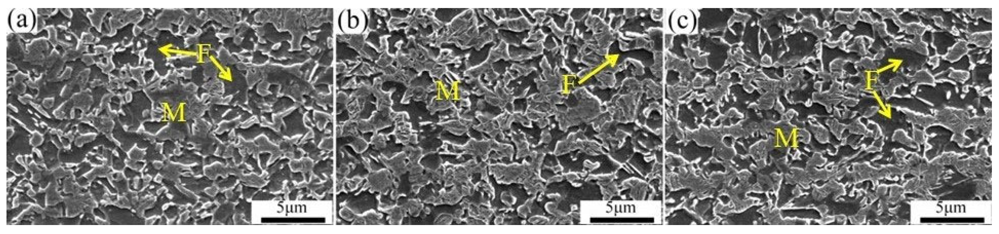
3.4.3. Thermo-Mechanically Affect Zone

The TMAZ of all joints was composed of ferrite and martensite, as shown in Figure 13. The peak temperature of TMAZ during FSW was between Ac1 and Ac3, the microstructure of TMAZ was composed of austenite and ferrite. As the material in TMAZ was only slightly extruded by the FSW tool and the dynamic recrystallization occurred partially, a large number of ferrite grains with irregular shapes could be observed [35]. Meanwhile, ferrite grains and prior austenite grains grew under the influence of high temperature. In the subsequent cooling process, austenite transformed into martensite and the ferrite in the two-phase region remained [36].

3.4.4. Heat Affected Zone

Compared with SZ and TMAZ, the HAZ was only affected by heat during the welding process. Figure 14 shows the SEM images of HAZ of the joints welded at different rotation speeds, where the microstructure mainly contained ferrite and tempered martensite. In HAZ, the microstructure experienced a peak temperature below A1, so the tempering of martensite occurred. Because of the high density of dislocations in martensite, carbon atoms gathered at the dislocations through diffusion, and then carbides precipitated in the subsequent tempering process to reduce the energy of the whole system [37]. Martensite in the HAZ began to decompose into ferrite and carbides when exposed to temperatures below A1. However, the tempering degree of martensite was mainly controlled by the temperature and holding time [38]. The high transverse speed made the HAZs of all joints undergo rapid heating and cooling. Because of the short holding time, the martensite in HAZ was not completely decomposed.

3.5. Mechanical Properties

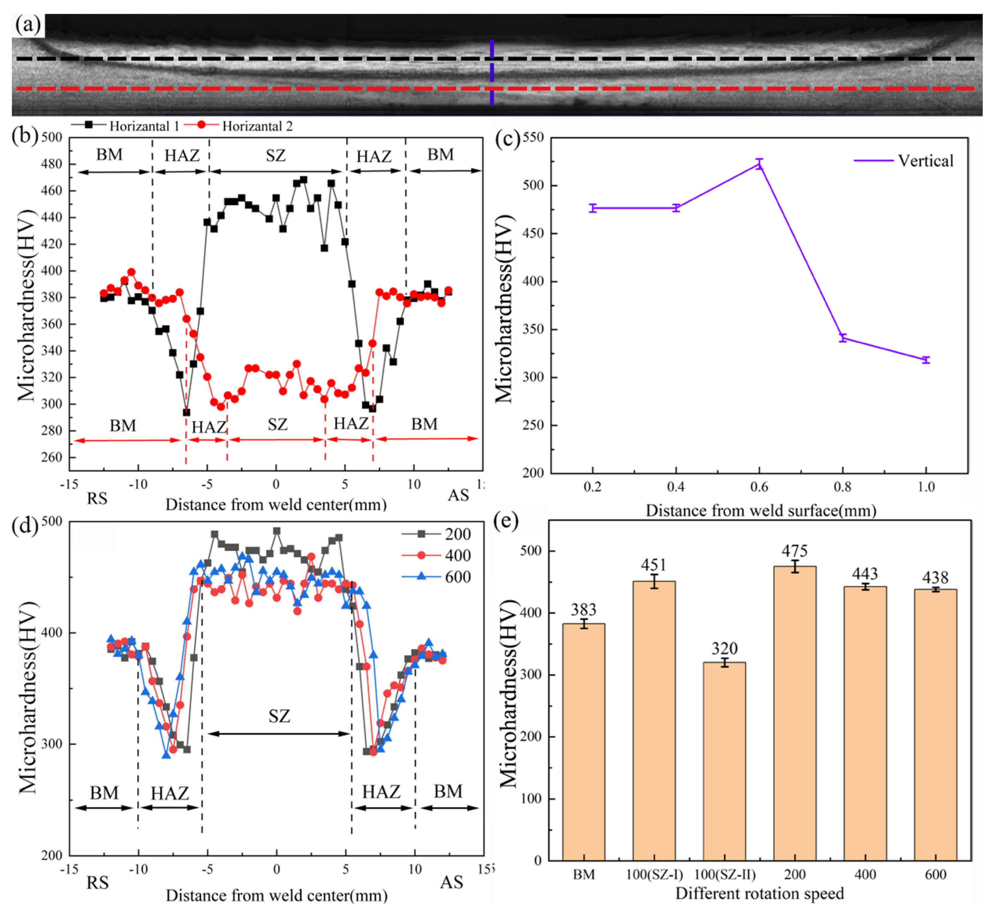
3.5.1. Microhardness

Vickers microhardness tests were carried out for all of the FSW joints. The black and red horizontal lines in Figure 15a represent the microhardness test position taken along the horizontal direction for the 100 rpm joint. The blue line was along the vertical direction of the weld center, and the test was conducted every 0.2 mm. For 200 rpm, 400 rpm, and 600 rpm joints, a horizontal line 0.5 mm away from the bottom of the joints was taken for the microhardness tests.
Figure 15b shows the microhardness distribution on different horizontal lines of the 100 rpm joint. BM showed an average microhardness of 380 HV. The average microhardness of SZ-Ⅰ and SZ-Ⅱ were 451 HV and 320 HV, respectively. The formation of fine martensite greatly improved the microhardness of SZ-Ⅰ. However, the tempering of martensite occurred in SZ-Ⅱ, which led to a large reduction in microhardness. Although the heat input of 100 rpm was very low, a significantly softened HAZ was still found. The minimum microhardness of HAZ was only 290 HV, which was only 76% of BM. Figure 15c shows the microhardness distribution in the vertical direction of the weld center. A significant increase in microhardness was observed at a distance of 0.6 mm from the joint surface. This area corresponded to the black boundary and its microhardness reached 520 HV. Because of the extrusion deformation of the black boundary and its low degree of recrystallization, its microhardness was relatively high.
For the 200 rpm, 400 rpm, and 600 rpm joints, the profile of the microhardness distribution were similar, which have a “W” shape. Figure 15d shows that SZ had the highest microhardness compared with other specific zones. At the edges of SZ, the microhardness sharply decreased to a minimum value, which corresponded to HAZ. As shown in Figure 15e, SZ shows the highest average microhardness (475 HV) at 200 rpm, while the average microhardness of 400 rpm and 600 rpm were 443 HV and 438 HV, respectively. The microhardness of SZ depends on the content of martensite and the degree of microstructure refinement. Generally, the effect of phase transformation strengthening in steel is stronger than the fine grain strengthening [39,40]. However, because of the self-tempering of martensite in SZ at 400 rpm and 600 rpm, the microhardness decreased. Although the heat input varied greatly under different parameters, the minimum microhardness value of HAZ was between 280–300 HV. Mohamed Ragab et al. [41] reported a similar phenomenon in the FSW study of martensitic stainless steel, and indicated that the similar average microhardness values in HAZ at various tool rotation rates was attributed to the small difference in the peak temperatures therein.

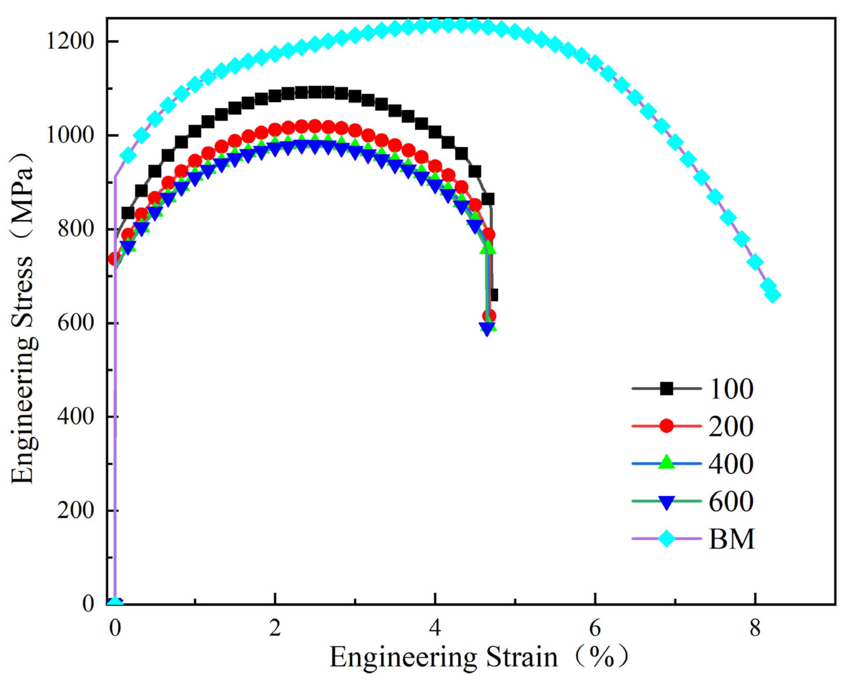
3.5.2. Tensile Strength

Figure 16 shows the stress−strain curves of the tensile specimens and the tensile results were shown in Table 2. The ultimate tensile strength (UTS) of BM was 1236 MPa. The maximum tensile strength of the 100 rpm joint was 1094 MPa, which reached 88.5% of that of BM. When the rotation speeds were 200 rpm, 400 rpm, and 600 rpm, the ultimate tensile strength of the joints were 1020 MPa, 985 MPa, and 979 MPa, respectively. The plastic elongation of all the joints was about 4.68 ± 0.3%, which decreased by about 42.5% compared with the BM.
As shown in Figure 17, the 100 rpm joint fractured in SZ due to the thinning of the SZ and the softened SZ-Ⅱ. When the rotation speed over 200 rpm, the joints were fractured in HAZ, which corresponded to the lowest point of microhardness [42,43].

4. Conclusions

In this work, OM, SEM, EBSD, and TEM were used to characterize the microstructure of the DP1180FSW joint, and the mechanical properties of the joint were also studied. The conclusions can be summarized as follows:
  • When welded at 100 rpm, a black boundary was formed in SZ and divided the SZ in two parts. Due to the low heat input, ultrafine grains were formed in SZ-Ⅰ and SZ-Ⅱ. The peak temperature of SZ was exceeded Ac3 when the rotation speed over 200 rpm.
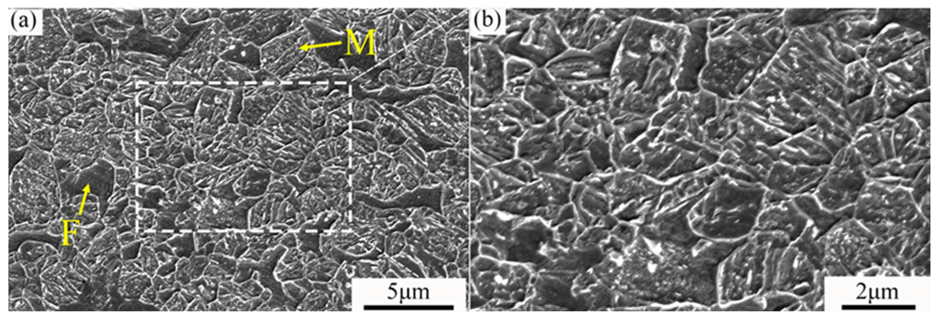
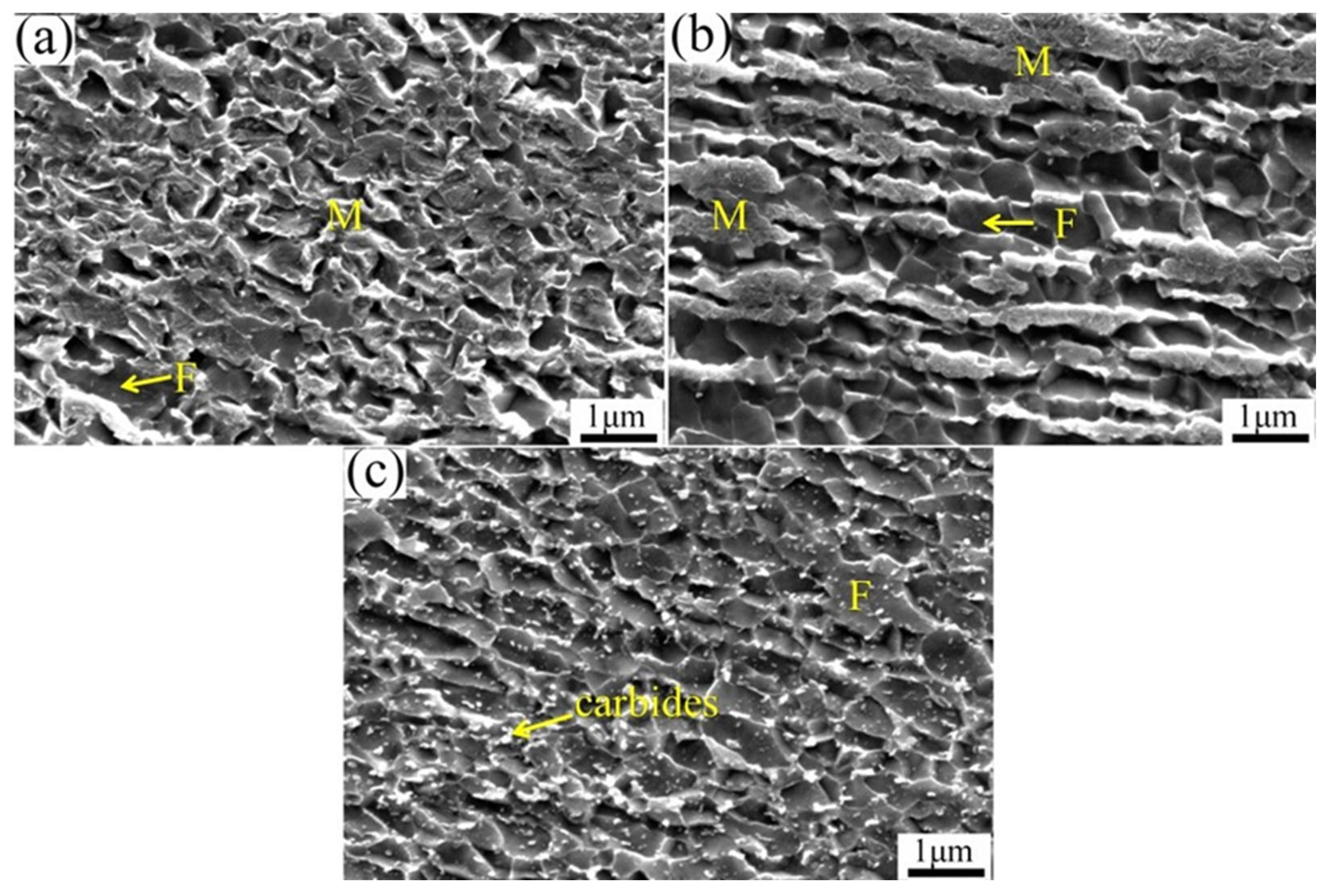
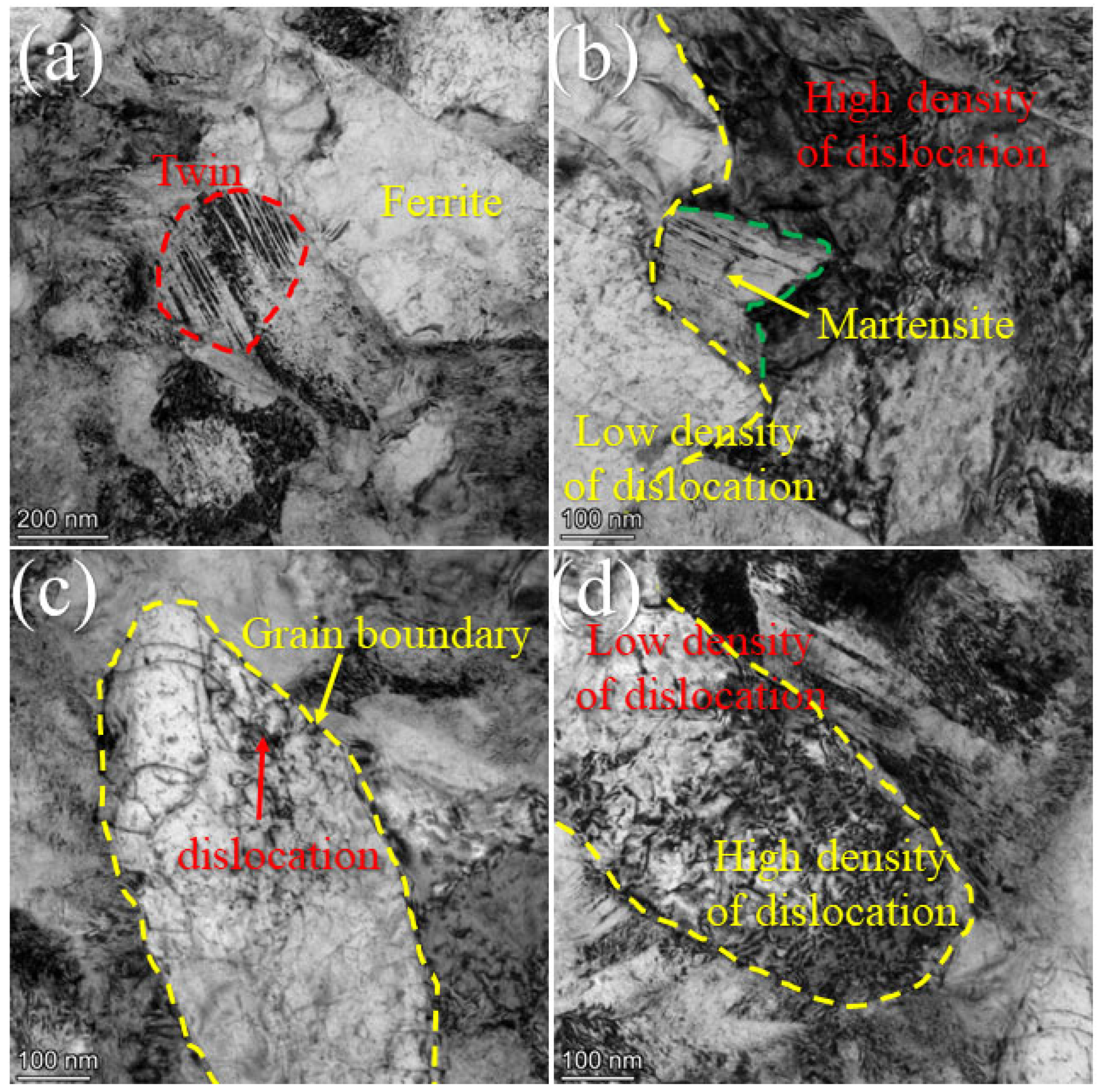
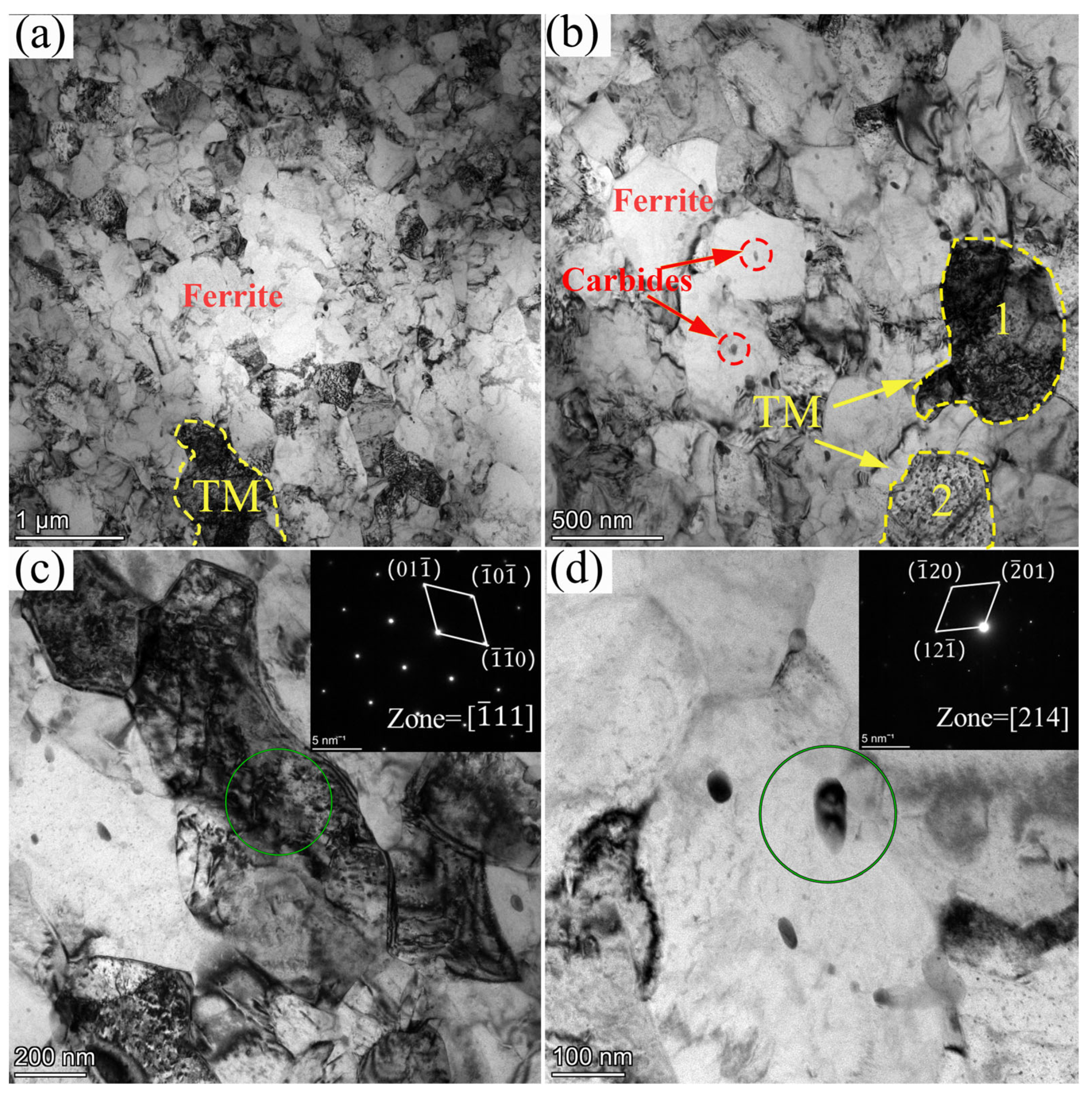
  • The TMAZ of all joints was composed of martensite and ferrite, while the tempered martensite occurred in HAZ.
  • All of the joints had the highest microhardness in SZ, while HAZ had the lowest microhardness. With increasing the rotation speed from 100 to 600 rpm, the UTS decreased from 1094 MPa to 981 MPa, and the plastic elongation of all joints was slightly decreased. The 100 rpm joint was fractured in SZ, while other joints fractured in HAZ.

Author Contributions

Conceptualization, Y.S., B.W. and L.W.; methodology, Y.S., B.W. and S.G.; investigation, C.Z., S.L. and N.W.; writing—original draft preparation, C.Z.; writing—review and editing, C.Z. and Q.Z.; project administration, Y.S., L.W. and S.G.; supervision, Y.S., L.W. and S.G. All authors have read and agreed to the published version of the manuscript.

Funding

This research was funded by the Henan provincial Joint Found of the National Natural Science Foundation of China. The authors are grateful for the financial support of the Henan provincial Joint Found of the National Natural Science Foundation of China (Grant No: U2004170).

Data Availability Statement

All metadata pertaining to this work will be made available on request.

Conflicts of Interest

The authors declare no conflict of interest.

References

  1. Zhao, J.; Jiang, Z. Thermomechanical processing of advanced high strength steel. Prog. Mater. Sci. 2018, 94, 174–242. [Google Scholar] [CrossRef]
  2. Rashid, M.S. Dual phase steels. Annu. Rev. Mater. Res. 1981, 11, 245–266. [Google Scholar] [CrossRef]
  3. Zhang, J.; Di, H.; Deng, Y.; Misra, R.D.K. Effect of martensite morphology and volume fraction on strain hardening and fracture behavior of martensite-ferrite dual phase steel. Mater. Sci. Eng. A 2015, 627, 230–240. [Google Scholar] [CrossRef]
  4. Andersson, J. Welding Metallurgy and Weldability of Superalloys. Metals 2020, 10, 143. [Google Scholar] [CrossRef] [Green Version]
  5. Fu, Z.H.; Yang, B.J.; Shan, M.L.; Li, T.; Zhu, Z.Y.; Ma, C.P.; Zhang, X.; Gou, G.Q.; Wang, Z.R.; Gao, W. Hydrogen embrittlement behavior of SUS301L-MT stainless steel laser-arc hybrid welded joint localized zones. Corros. Sci. 2020, 164, 108337. [Google Scholar] [CrossRef]
  6. Chen, Y.; Sun, S.; Zhang, T.; Zhou, X.; Li, S. Effects of post-weld heat treatment on the microstructure and mechanical properties of laser-welded NiTi/304SS joint with Ni filler. Mater. Sci. Eng. A 2020, 771, 138545. [Google Scholar] [CrossRef]
  7. He, H.; Farnoosh, F.; Volpp, J.; Robertson, S.M.; Vuorinen, E. Microstructure and Mechanical Properties of Laser-Welded DP Steels Used in the Automotive Industry. Materials 2021, 14, 456. [Google Scholar] [CrossRef]
  8. Alves, P.H.O.M.; Lima, M.S.F.; Raabe, D.; Sandim, H.R.Z. Laser beam welding of dual-phase DP1000 steel. J. Mater. Process. Technol. 2018, 252, 498–510. [Google Scholar] [CrossRef]
  9. Miles, M.P.; Pew, J.; Nelson, T.W.; Li, M. Comparison of formability of friction stir welded and laser welded dual phase 590 steel sheets. Sci. Technol. Weld. Join. 2006, 11, 384–388. [Google Scholar] [CrossRef]
  10. Fang, J.X.; Wang, J.X.; Wang, Y.J.; He, H.T.; Zhang, D.B.; Cao, Y. Microstructure evolution and deformation behavior during stretching of a compositionally inhomogeneous TWIP-TRIP cantor-like alloy by laser powder deposition. Mater. Sci. Eng. A 2022, 847, 143319. [Google Scholar] [CrossRef]
  11. Aktarera, S.M.; Küçükömeroğlub, T.; Davut, K. Friction stir processing of dual phase steel: Microstructural evolution and mechanical properties. Mater. Charact. 2019, 15, 109787. [Google Scholar] [CrossRef]
  12. Mahdi, M.; Amir, H.K.; Massoud, G.; Leo, A.I.K. Friction stir welding of advanced high strength dual phase steel: Microstructure, mechanical properties and fracture behavior. Mater. Sci. Eng. A 2020, 76, 138490. [Google Scholar]
  13. Xie, G.M.; Cui, H.B.; Luo, Z.A.; Yu, W.; Ma, J.; Wang, G.D. Effect of Rotation Rate on Microstructure and Mechanical Properties of Friction Stir Spot Welded DP780 Steel. J. Mater. Sci. Technol. 2016, 32, 326–332. [Google Scholar] [CrossRef]
  14. Wang, Z.W.; Xie, G.M.; Wang, D.; Zhang, H.; Ni, D.R.; Xue, P.; Xiao, B.L.; Ma, Z.Y. Microstructural Evolution and Mechanical Behavior of Friction-Stir-Welded DP1180 Advanced Ultrahigh Strength Steel. Acta Metall. Sin. Engl. Lett. 2020, 33, 58–66. [Google Scholar] [CrossRef] [Green Version]
  15. Padhy, G.K.; Wu, C.S.; Gao, S. Friction stir based welding and processing technologies-processes, parameters, microstructures and applications: A review. J. Mater. Sci. Technol. 2018, 34, 1–38. [Google Scholar] [CrossRef]
  16. Trzaska, J.; Dobrzański, L.A. Modelling of CCT diagrams for engineering and constructional steels. J. Mater. Process. Technol. 2008, 192, 504–510. [Google Scholar] [CrossRef]
  17. Ramesh, R.; Dinaharan, I.; Kumar, R.; Akinlabi, E.T.T. Microstructure and mechanical characterization of friction stir welded high strength low alloy steels. Mater. Sci. Eng. A 2017, 687, 39–46. [Google Scholar] [CrossRef]
  18. Crăcănel, M.O.; Niţu, E.L.; Iordache, D.M. Characteristics of steels joints obtained by the FSW process-a brief review. Key Eng. Mater. 2021, 890, 120–137. [Google Scholar] [CrossRef]
  19. Kim, Y.G.; Kim, J.S.; Kim, I.J. Effect of process parameters on optimum welding condition of DP590 steel by friction stir welding. J. Mech. Sci. Technol. 2014, 28, 5143–5148. [Google Scholar] [CrossRef]
  20. Gladys, P.M.; Hugo, L.F.; Patricia, Z.R.; Argelia, M.P.; Felipe, A.R.V. Microstructural Development in a TRIP-780 Steel Joined by Friction Stir Welding (FSW): Quantitative Evaluations and Comparisons with EBSD Predictions. Soldag. Insp. 2016, 2, 146–155. [Google Scholar]
  21. Avinish, T.; Pardeep, P.; Saurav, S.; Pankaj, B. CFD Modelling of Temperature Distribution and Material Flow Investigation During FSW of DH36 Shipbuilding Grade Steel. Trans. Indian Inst. Met. 2020, 7, 2291–2307. [Google Scholar]
  22. Cho, J.H.; Boyce, D.E.; Dawson, P.R. Modeling strain hardening and texture evolution in friction stir welding of stainless steel. Mater. Sci. Eng. A-Struct. 2005, 39, 146–163. [Google Scholar] [CrossRef]
  23. Sun, Y.F.; Fujii, H.; Satoa, Y.; Morisada, Y. Friction stir spot welding of SPCC low carbon steel plates at extremely low welding temperature. J. Mater. Sci. Technol. 2019, 35, 733–741. [Google Scholar] [CrossRef]
  24. Lobodyuk, V.A.; Meshkov, Y.Y. Peculiarities of the crystal structure of the Martensite in Carbon Steels. Metallofiz. Nov. Tekh. 2021, 4, 1031–1043. [Google Scholar] [CrossRef]
  25. Yamamoto, H.; Nishiura, T.; Nishibata, H.; Yonemura, M.; Fujiwara, K.; Kawano, K.; Ito, K. Surface Microstructure Modifications of Low Carbon Steel Welds Produced by Low-Heat-Input Friction Stir Processing. Mater. Trans. 2020, 61, 1613–1619. [Google Scholar] [CrossRef]
  26. Sorger, G.; Sarikka, T.; Vilaca, P.; Santos, T.G. Effect of processing temperatures on the properties of a high-strength steel welded by FSW. Weld. World 2018, 62, 1173–1185. [Google Scholar] [CrossRef] [Green Version]
  27. Di Martino, S.F.; Thewlis, G. Transformation Characteristics of Ferrite/Carbide Aggregate in Continuously Cooled, Low Carbon-Manganese Steels. Metall. Mater. Trans. A Phys. Metall. Mater. Sci. 2014, 45, 579–594. [Google Scholar] [CrossRef]
  28. Sackl, S.; Clemens, H.; Primig, S. Investigation of the Self Tempering Effect of Martensite by Means of Atom Probe Tomography. Prakt. Metallogr. Pract. Metallogr. 2015, 52, 374–383. [Google Scholar] [CrossRef]
  29. Iqbal, Z.; Bazoune, A.; Al-Badour, F.; Shuaib, A.; Merah, N. Effect of Tool Rotational Speed on Friction Stir Welding of ASTM A516-70 Steel Using W-25%Re Alloy Tool. Arab. J. Sci. Eng. 2019, 44, 1233–1242. [Google Scholar] [CrossRef]
  30. Furuhara, T.; Kobayashi, K.; Maki, T. Control of cementite precipitation in lath martensite by rapid heating and tempering. ISIJ Int. 2005, 44, 1937–1944. [Google Scholar] [CrossRef]
  31. Long, S.-L.; Liang, Y.-L.; Jiang, Y.; Liang, Y.; Yang, M.; Yi, Y.-L. Effect of quenching temperature on martensite multi-level microstructures and properties of strength and toughness in 20CrNi2Mo steel. Mater. Sci. Eng. A 2016, 44, 38–47. [Google Scholar] [CrossRef]
  32. Celada-Casero, C.; Sietsma, J.; Santofimia, M.J. The role of the austenite grain size in the martensitic transformation in low carbon steels. Mater. Des. 2019, 167, 107625. [Google Scholar] [CrossRef]
  33. Fan, Z.J.; Shen, Y.Z.; Xu, Z.Q.; Zhu, P.C.; Liu, H.; Ma, Y.F.; Guan, W.Q. Evolution of Precipitate Phases in Ferritic and Martensitic Steel P92 During Normalizing and Tempering. JOM 2022, 74, 3578–3594. [Google Scholar] [CrossRef]
  34. Ahmadi, M.; Pahlavani, M.; Rahmatabadi, D.; Marzbanrad, J.; Hashemi, R.; Afkar, A. An Exhaustive Evaluation of Fracture Toughness, Microstructure, and Mechanical Characteristics of Friction Stir Welded Al6061 Alloy and Parameter Model Fitting Using Response Surface Methodology. J. Mater. Eng. Perform. 2022, 31, 3418–3436. [Google Scholar] [CrossRef]
  35. Heidarzadeh, A.; Mironov, S.; Kaibyshev, R.; Çam, G.; Simar, A.; Gerlich, A.; Khodabakhshi, F.; Mostafaei, A.; Field, D.; Robson, J.; et al. Friction stir welding/processing of metals and alloys: A comprehensive review on microstructural evolution. Prog. Mater. Sci. 2021, 117, 100752. [Google Scholar] [CrossRef]
  36. Zhao, X.; Yang, Z.; Zheng, C.; Zhang, F.; Long, X. In situ observation of bainitic transformation behavior in medium carbon bainitic steel. J. Mater. Res. Technol. 2022, 21, 330–338. [Google Scholar] [CrossRef]
  37. Morsdorf, L.; Emelina, E.; Gault, B.; Herbig, M.; Tasan, C. Carbon redistribution in quenched and tempered lath martensite. Acta Mater. 2021, 205, 116521. [Google Scholar] [CrossRef]
  38. Hernandez, V.B.; Nayak, S.S.; Zhou, Y. Tempering of martensite in dual-phase steels and its effects on softening behavior. Metall. Mater. Trans. A Phys. Metall. Mater. Sci. 2011, 42, 3115–3129. [Google Scholar] [CrossRef]
  39. Mine, Y.; Hirashita, K.; Takashima, H.; Matsuda, M.; Takashima, K. Micro-tension behaviour of lath martensite structures of carbon steel. Mater. Sci. Eng. A 2013, 560, 535–544. [Google Scholar] [CrossRef]
  40. Galindo-Nava, E.; Rivera-Díaz-Del-Castillo, P. A model for the microstructure behaviour and strength evolution in lath martensite. Acta Mater. 2015, 98, 81–93. [Google Scholar] [CrossRef] [Green Version]
  41. Ragab, M.; Liu, H.; Ahmed, M.M.; Yang, G.J.; Lou, Z.J.; Mehboob, G. Microstructure evolution during friction stir welding of 1Cr11Ni2W2MoV martensitic stainless steel at different tool rotation rates. Mater. Charact. 2021, 182, 111561. [Google Scholar] [CrossRef]
  42. Gaddam, S.; Haridas, R.S.; Tammana, D.; Sanabria, C.; Lammi, C.J.; Berman, D.; Mishra, R.S. Double-sided friction stir welding of Nitronic-40 stainless steel for application in tokamak devices. J. Mater. Sci. Technol. 2023, 159, 170–183. [Google Scholar] [CrossRef]
  43. Aminzadeh, A.; Parvizi, A.; Safdarian, R.; Rahmatabadi, D. Comparison between laser beam and gas tungsten arc tailored welded blanks via deep drawing. Proc. Inst. Mech. Eng. Part B J. Eng. Manuf. 2021, 235, 673–688. [Google Scholar] [CrossRef]
Figure 1. (a) Photo taken during the FSW of DP steel; (b) the appearance of pcBN rotating tool; (c) dimension of tensile specimen.
Metals 13 01164 g001
Figure 2. Appearances of the joints obtained at different tool rotation speeds: (a) 100 rpm; (b) 200 rpm; (c) 400 rpm; (d) 600 rpm.
Metals 13 01164 g002
Figure 3. The axis force during the FSW.
Metals 13 01164 g003
Figure 4. Cross-sectional OM macrostructure of the joints: (a) 100 rpm; (b) 200 rpm; (c) 400 rpm; (d) 600 rpm.
Metals 13 01164 g004
Figure 5. (a,b) SEM images of BM.
Metals 13 01164 g005
Figure 6. (a) IPF map and (b) misorientation distribution of BM.
Metals 13 01164 g006
Figure 7. SEM images of 100 rpm joint: (a) SZ-I; (b) black boundary; (c) SZ-Ⅱ.
Metals 13 01164 g007
Figure 8. (a) IPF maps, (b) distribution of grain size, (c) misorientation distribution in SZ-I; and (d) IPF maps, (e) distribution of grain size, and (f) misorientation distribution in SZ-Ⅱ of the joint welded at 100 rpm.
Metals 13 01164 g008
Figure 9. TEM images of SZ-Ⅰ of the 100 rpm joint: (a) martensitic twins; (b) lath martensite; (c) ferrite; (d) the difference of dislocation density.
Metals 13 01164 g009
Figure 10. TEM images of SZ-Ⅱ. (a,b) microstructure of tempered martensite, ferrite, and carbides; (c) tempered martensite; (d) Fe3C.
Metals 13 01164 g010
Figure 11. SEM images of SZ of the joint welded at (a) 200 rpm; (b) 400 rpm; (c) 600 rpm.
Metals 13 01164 g011
Figure 12. EBSD characterization of SZ at different rotation speeds: (ac) IPF maps; (df) prior austenite grain boundary map; (gi) misorientation distribution.
Metals 13 01164 g012
Figure 13. SEM images of TMAZ: (a) 200 rpm; (b) 400 rpm; (c) 600 rpm.
Metals 13 01164 g013
Figure 14. SEM images of HAZ: (a) 100 rpm; (b) 200 rpm; (c) 400 rpm; (d) 600 rpm.
Metals 13 01164 g014
Figure 15. (a) Microhardness testing; (b) microhardness distribution of SZ-Ⅰ and SZ-Ⅱ along horizontal direction; (c) microhardness distribution along vertical direction for 100 rpm joint; (d) microhardness distribution at different rotation speeds; (e) average microhardness of SZ of the joints.
Metals 13 01164 g015
Figure 16. Stress−strain curves.
Metals 13 01164 g016
Figure 17. Fracture position of tensile specimens at different rotation speed: (a) 100 rpm; (b) 200 rpm; (c) 400 rpm; (d) 600 rpm.
Metals 13 01164 g017
Table 1. Chemical composition of DP1180 steel (wt.%).
CSiMnCrMoCuAlSPFe
0.180.602.40.020.010.020.050.0050.01Bal.
Table 2. Tensile results.
Tool Rotation Speed (rpm)Ultimate Tensile Strength (MPa)Yield
Strength (MPa)
Plastic
Elongation (%)
Failure
Location
BM1236 ± 109648.22-
1001094 ± 108454.71SZ
2001020 ± 88064.68HAZ
400985 ± 67334.67HAZ
600981 ± 57334.65HAZ
Disclaimer/Publisher’s Note: The statements, opinions and data contained in all publications are solely those of the individual author(s) and contributor(s) and not of MDPI and/or the editor(s). MDPI and/or the editor(s) disclaim responsibility for any injury to people or property resulting from any ideas, methods, instructions or products referred to in the content.

