
Study on the Wear Resistance of Ni-Co-ZrO2 Composite Coatings with Different ZrO2 Nanoparticle Concentrations Prepared Using Electrodeposition on the Micro-Surface of Spindle Hook Teeth

Abstract
:1. Introduction
2. Materials and Methods
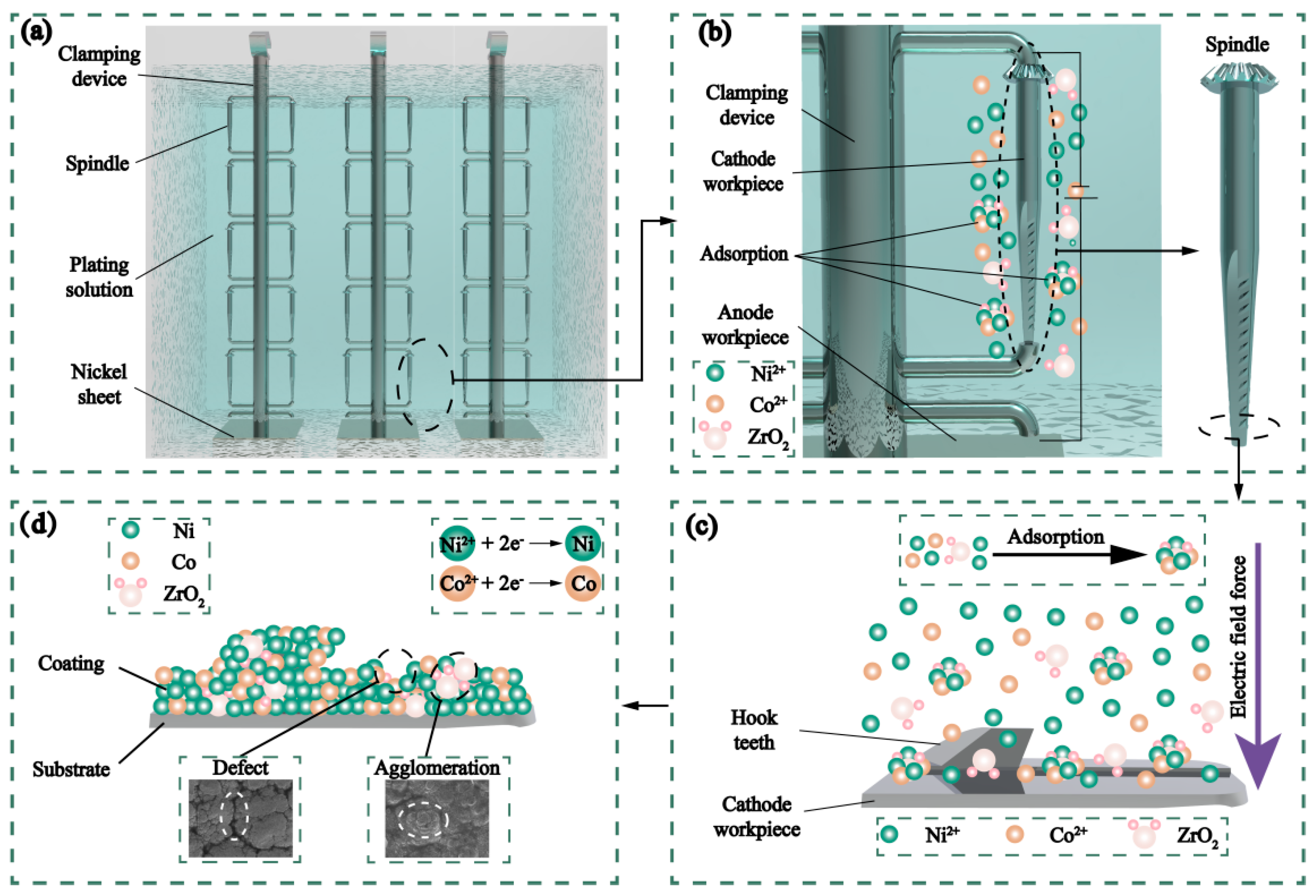
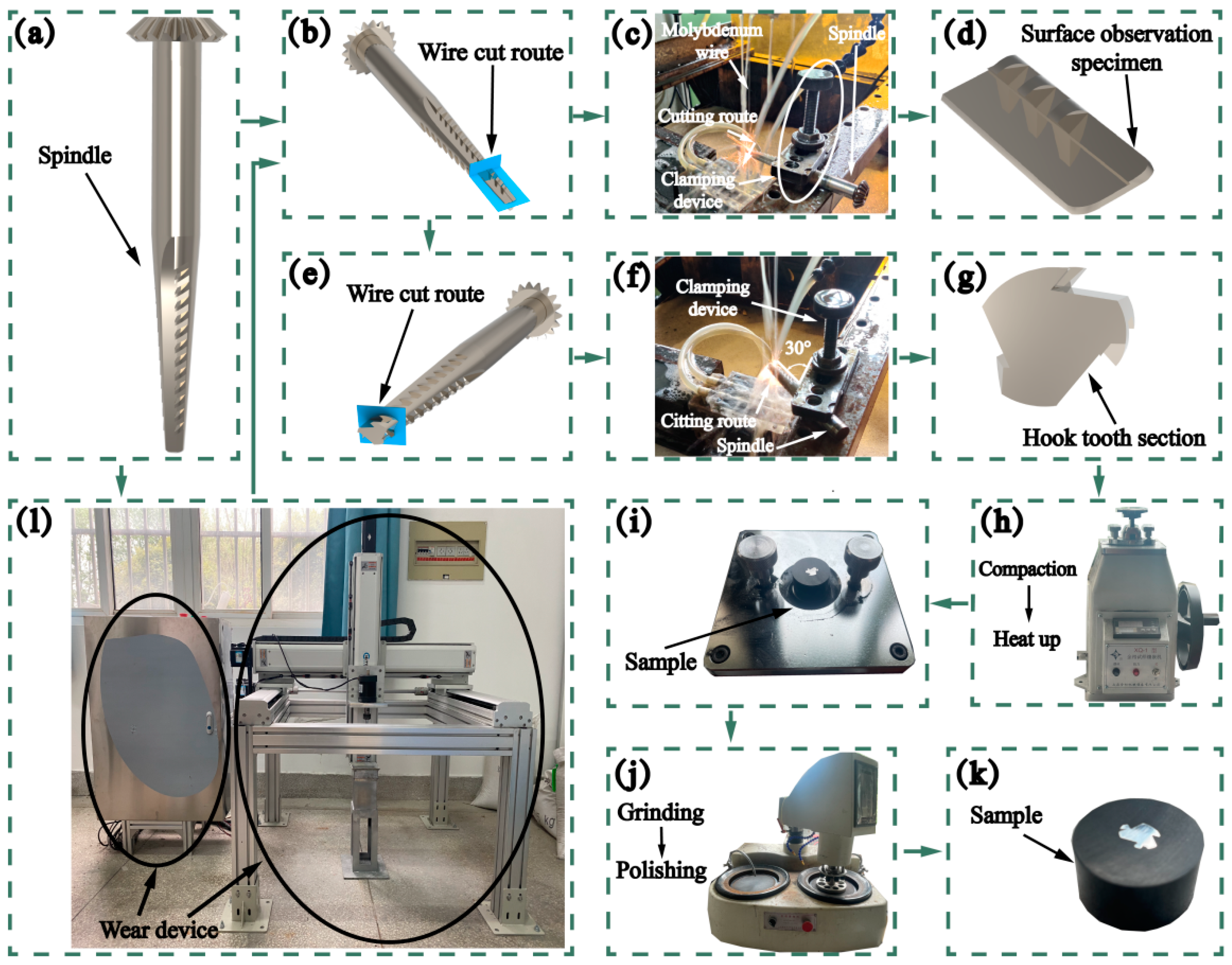
2.1. Experimental Procedure
2.2. Instruments
3. Results and Discussion
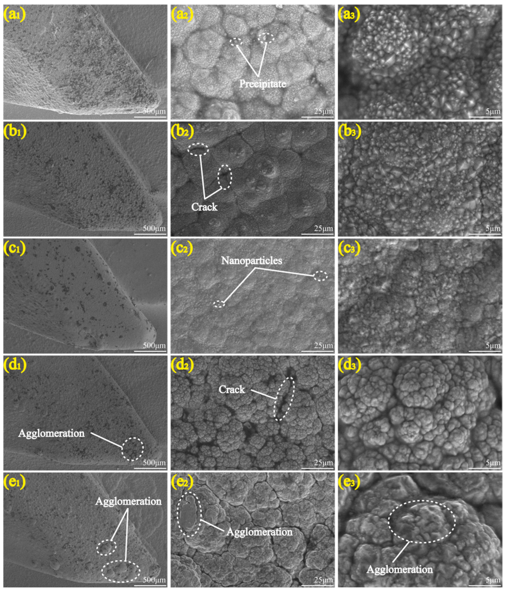
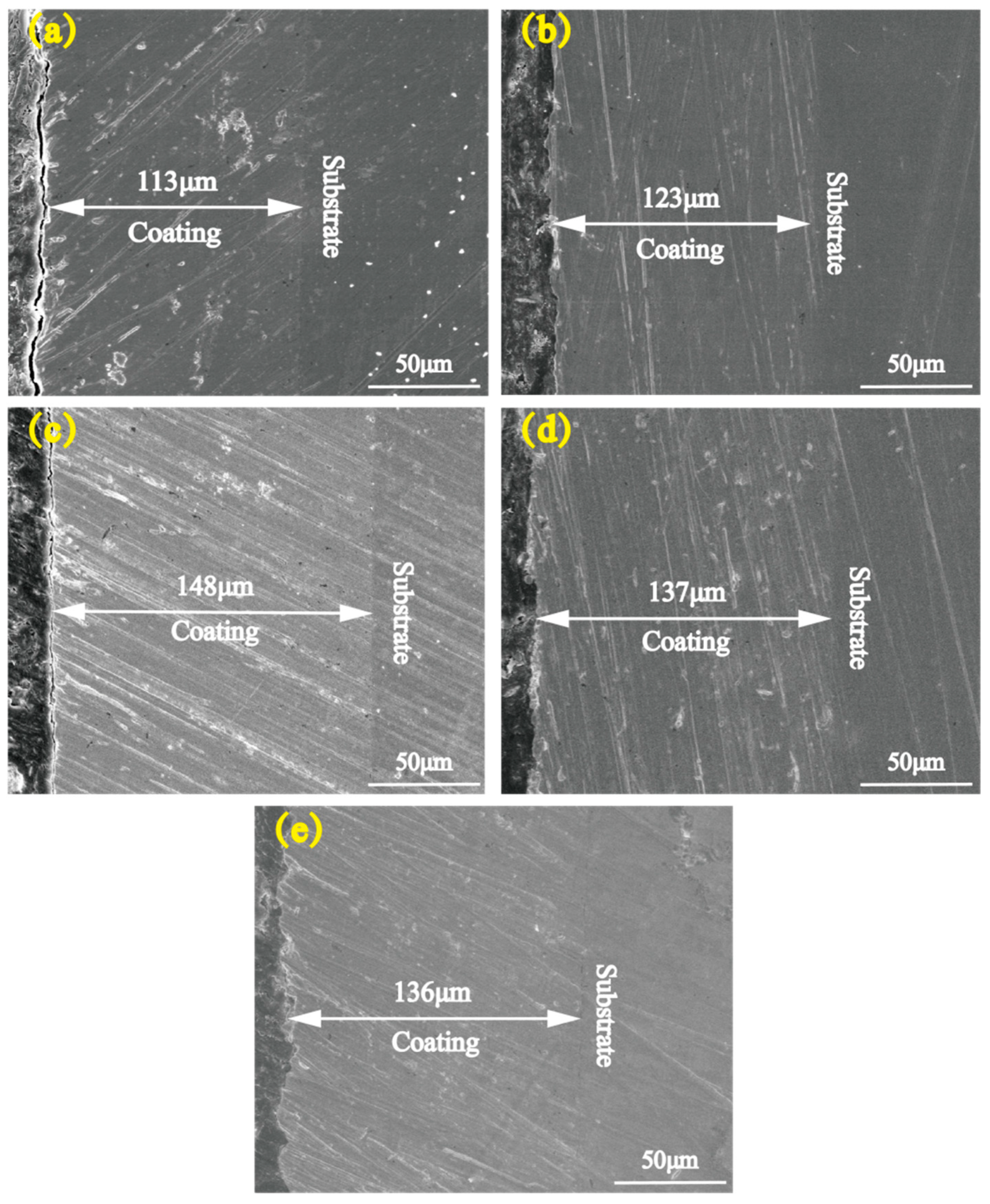
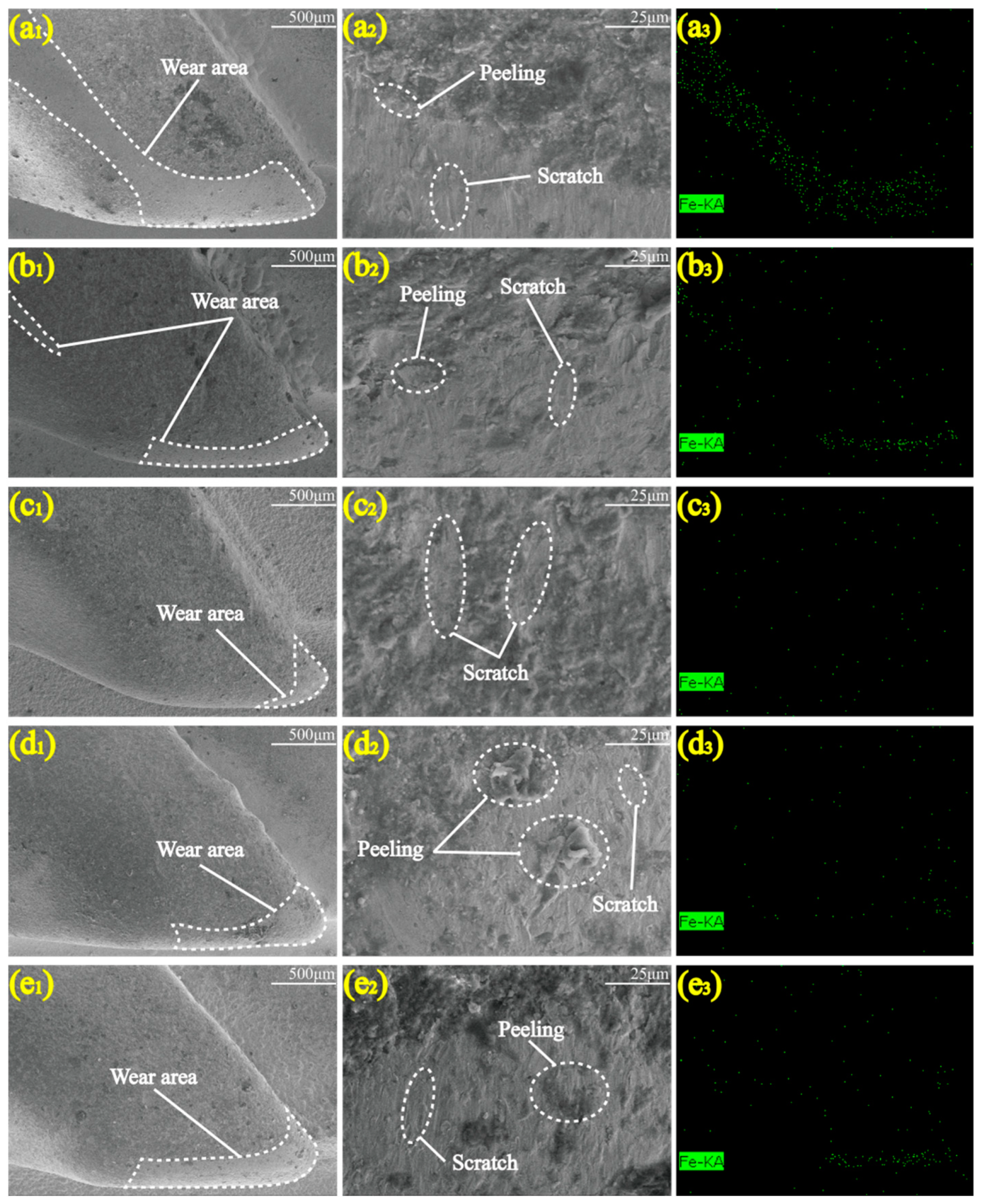
3.1. Micromorphology
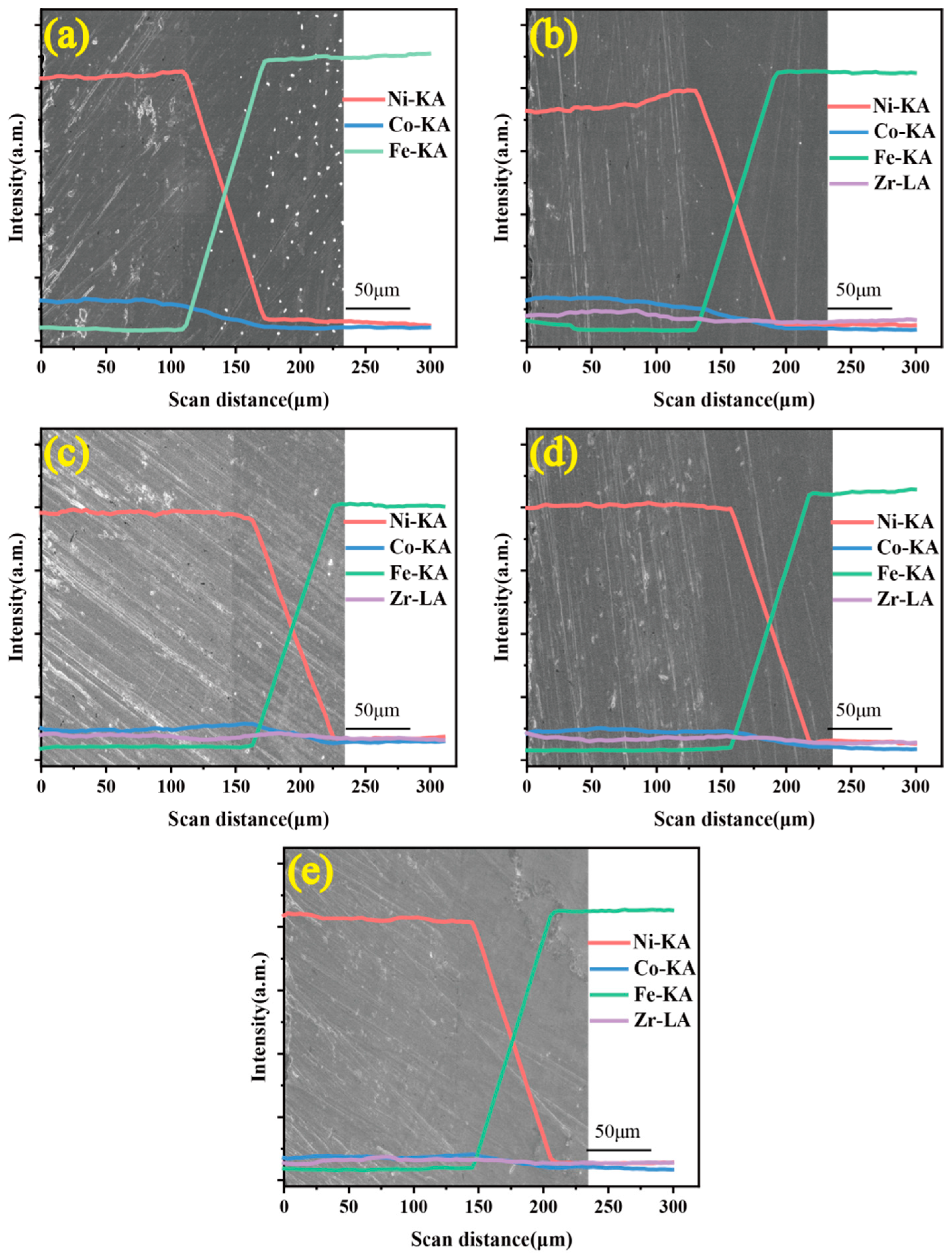
3.2. Elemental Distribution
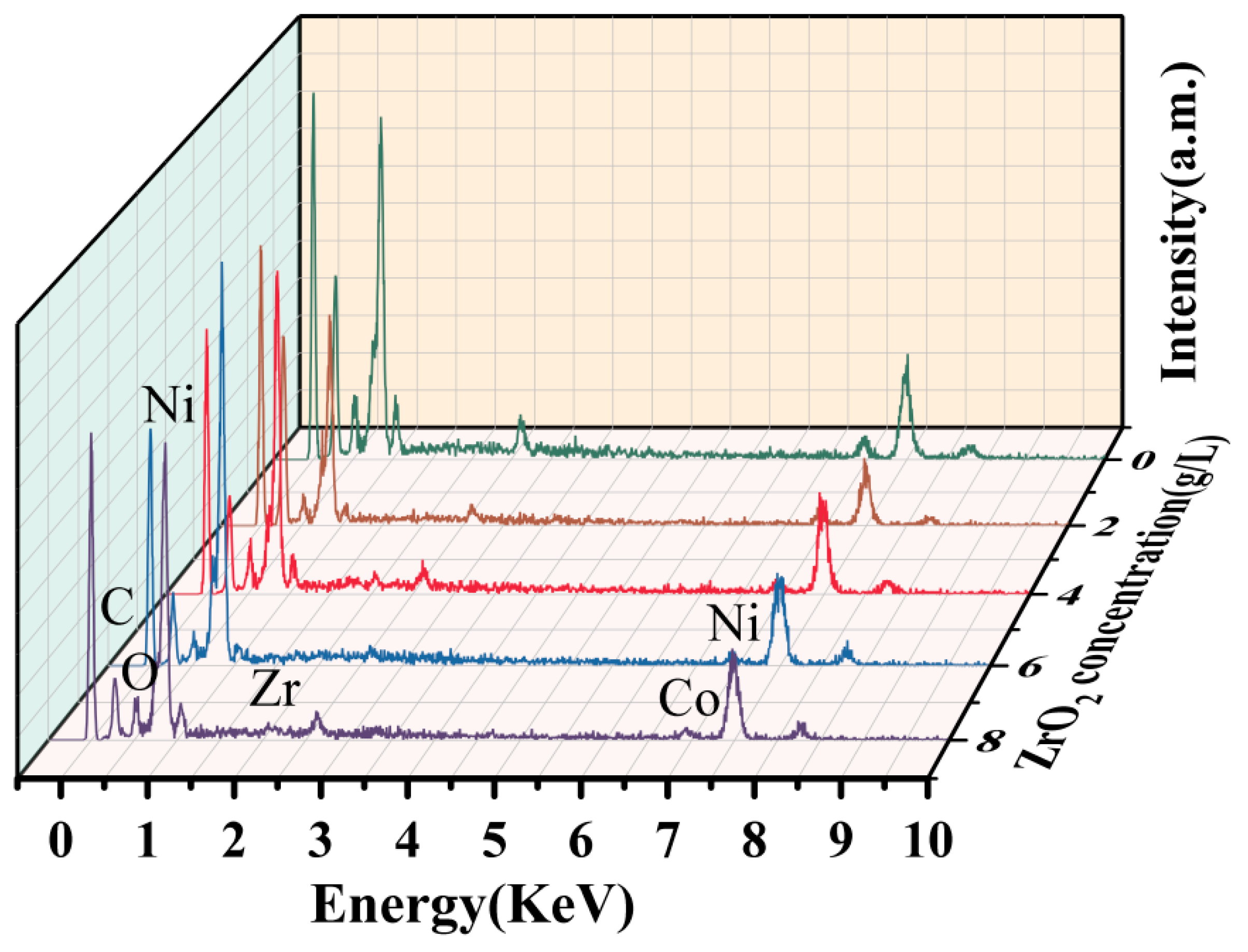
3.3. Composition
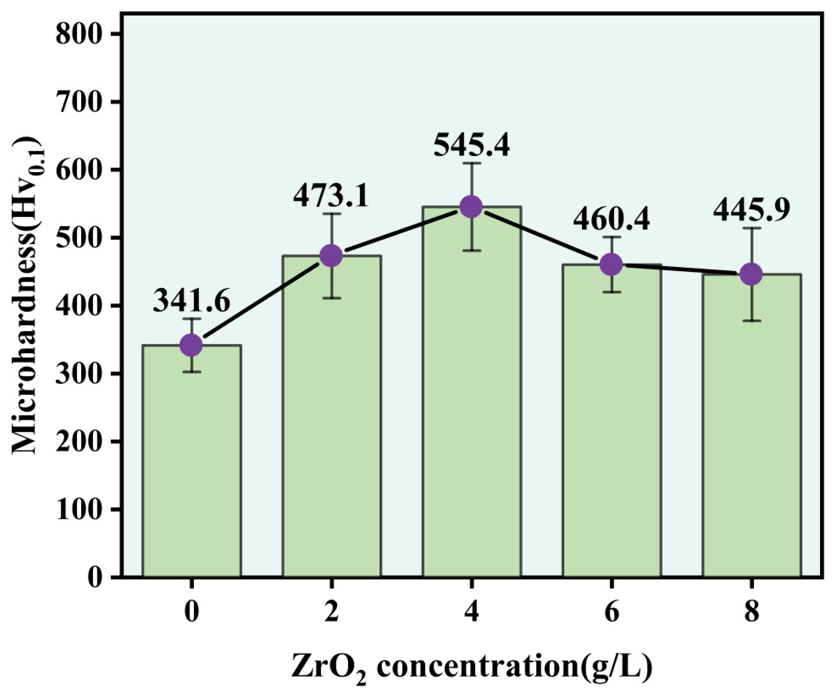
3.4. Microhardness
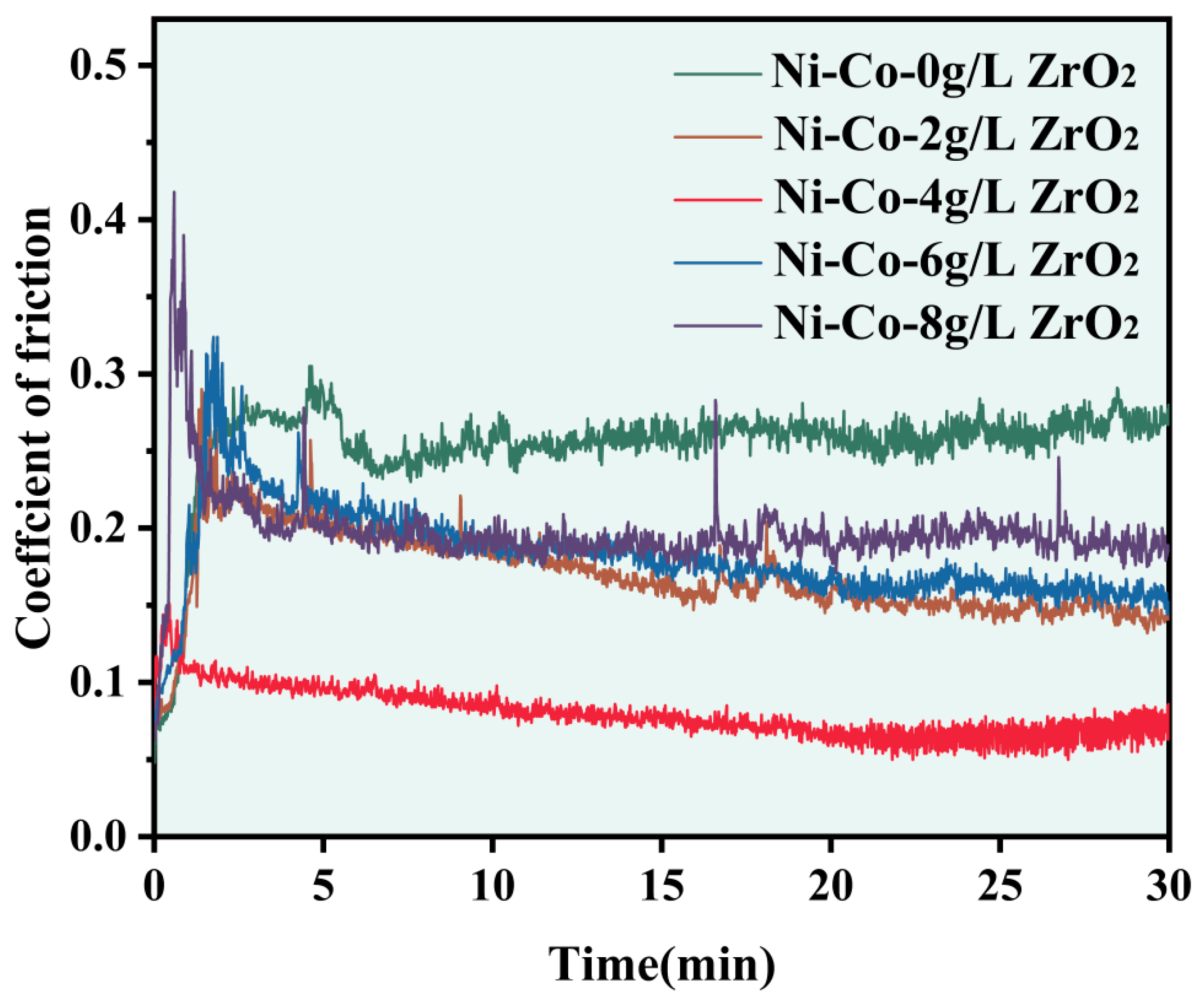
3.5. Tribological Behaviour
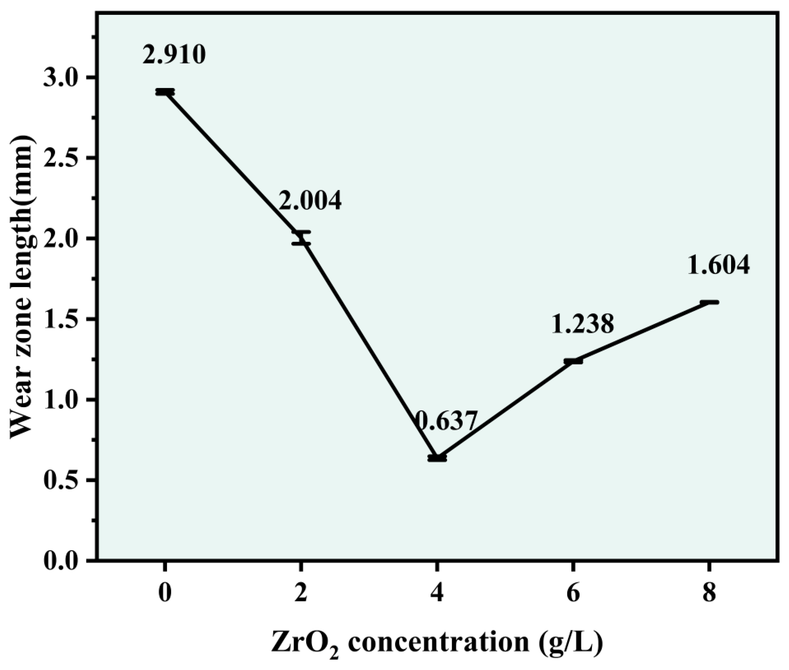
3.6. Wear Resistance
4. Conclusions
- (1)
- There occurred a blocky structure on the surface of the Ni-Co-ZrO2 composite coating. When the ZrO2 nanoparticles were at a concentration of 4 g/L, the composite coating had the most uniform and compact surface, with a thickness increased from 113 to 148 μm.
- (2)
- The addition of ZrO2 nanoparticles is conducive to the co-deposition of Ni and Co in the Ni-Co substrate, leading to higher deposition efficiency and stronger element permeation. When the ZrO2 nanoparticles were at a concentration of 4–6 g/L, Ni2+ and CO2+ had high deposition efficiency. At the same time, when the ZrO2 nanoparticles were at a concentration of 4 g/L, the element permeation was obvious.
- (3)
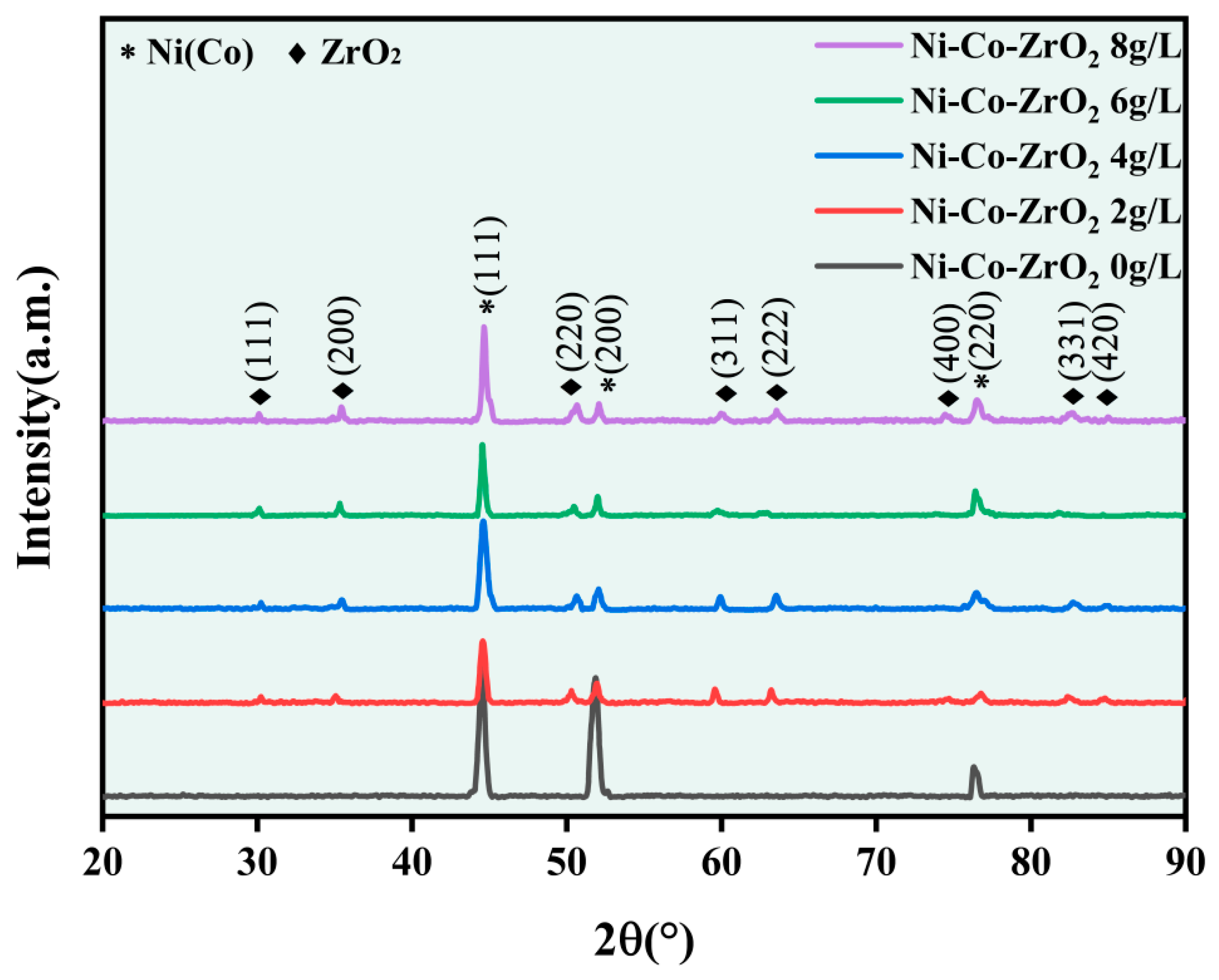
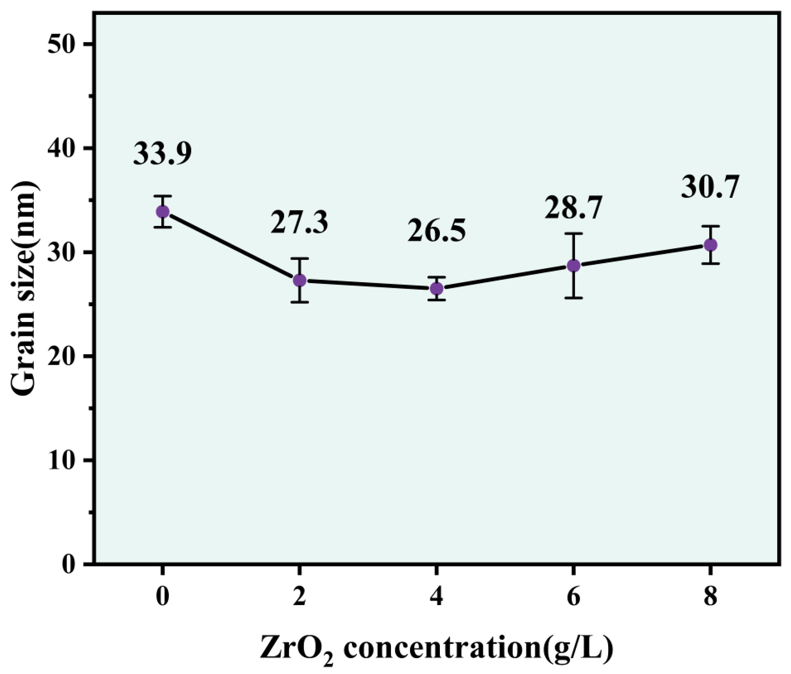
- The Ni-Co-ZrO2 composite coating has a face-centered cubic (FCC) structure as its crystal structure, and the ZrO2 nanoparticles in the Ni-Co-ZrO2 composite coating promoted the dominant orientation of composite coating growth played the role of grain refinement and reduced the average grain size of the composite coating.
- (4)
- The addition of ZrO2 nanoparticles led to a significant increase in the microhardness of the composite coating. When the ZrO2 nanoparticles were at a concentration of 4 g/L, the composite coating had a microhardness of 545.4 Hv0.1. Compared with the Ni-Co composite coating, the microhardness value increased by 59.66%.
- (5)
- Compared with the Ni-Co composite coating, the Ni-Co-ZrO2 composite coating had a smaller friction coefficient. When the ZrO2 nanoparticles were at a concentration of 4 g/L, the friction coefficient of the composite coating was a minimum of 0.06.
- (6)
- In the simulated wear test, the wear resistance of the Ni-Co-ZrO2 composite coating was higher than that of the Ni-Co composite coating. When the ZrO2 nanoparticles were at a concentration of 4 g/L, the wear area only occurred at the tips of the hook teeth, with the smallest wear area and the highest wear resistance.
Author Contributions
Funding
Data Availability Statement
Conflicts of Interest
References
- Zhang, Y.; Tian, Y.; Meng, Y. Wear Behavior of Spindles of Cotton Picker in Field Work. J. Tribol. 2020, 143, 021703. [Google Scholar] [CrossRef]
- Gu, Y.; Zhang, H.; Fu, X.; Wang, L.; Wang, J.; Cai, Y.; Li, H. Comparative Analysis of the Wear Performance of Spindle Hook Teeth During Fieldwork. J. Tribol. 2022, 144, 011706. [Google Scholar] [CrossRef]
- Pina, J.; Dias, A.; François, M.; Lebrun, J.L. Residual Stresses and Crystallographic Texture in Hard-Chromium Electroplated Coatings. Surf. Coat. Technol. 1997, 96, 148–162. [Google Scholar] [CrossRef]
- Weiss, B.; Lefebvre, A.; Sinot, O.; Marquer, M.; Tidu, A. Effect of Grinding on the Sub-Surface and Surface of Electrodeposited Chromium and Steel Substrate. Surf. Coat. Technol. 2015, 272, 165–175. [Google Scholar] [CrossRef]
- Jeong, D.H.; Erb, U.; Aust, K.T.; Palumbo, G. The Relationship between Hardness and Abrasive Wear Resistance of Electrodeposited Nanocrystalline Ni–P Coatings. Scr. Mater. 2003, 48, 1067–1072. [Google Scholar] [CrossRef]
- Sriraman, K.R.; Ganesh Sundara Raman, S.; Seshadri, S.K. Synthesis and Evaluation of Hardness and Sliding Wear Resistance of Electrodeposited Nanocrystalline Ni–W Alloys. Mater. Sci. Eng. A 2006, 418, 303–311. [Google Scholar] [CrossRef]
- Bekish, Y.N.; Poznyak, S.K.; Tsybulskaya, L.S.; Gaevskaya, T.V. Electrodeposited Ni–B Alloy Coatings: Structure, Corrosion Resistance and Mechanical Properties. Electrochim. Acta 2010, 55, 2223–2231. [Google Scholar] [CrossRef]
- Beltowska-Lehman, E.; Bigos, A.; Indyka, P.; Kot, M. Electrodeposition and Characterisation of Nanocrystalline Ni–Mo Coatings. Surf. Coat. Technol. 2012, 211, 67–71. [Google Scholar] [CrossRef]
- Ataie, S.A.; Zakeri, A. Improving Tribological Properties of (Zn–Ni)/Nano Al2O3 Composite Coatings Produced by Ultrasonic Assisted Pulse Plating. J. Alloys Compd. 2016, 674, 315–322. [Google Scholar] [CrossRef]
- Pellicer, E.; Varea, A.; Pané, S.; Sivaraman, K.M.; Nelson, B.J.; Suriñach, S.; Baró, M.D.; Sort, J. A Comparison between Fine-Grained and Nanocrystalline Electrodeposited Cu–Ni Films. Insights on Mechanical and Corrosion Performance. Surf. Coat. Technol. 2011, 205, 5285–5293. [Google Scholar] [CrossRef] [Green Version]
- Torabinejad, V.; Rouhaghdam, A.S.; Aliofkhazraei, M.; Allahyarzadeh, M.H. Electrodeposition of Ni–Fe and Ni–Fe-(Nano Al2O3) Multilayer Coatings. J. Alloys Compd. 2016, 657, 526–536. [Google Scholar] [CrossRef]
- Dong, Y.; Sun, W.; Liu, X.; Ma, M.; Zhang, Y.; Liu, Y. Electrophoretic-Deposition of Graphene and Microstructure and Friction Behavior of Ni–Graphene Composite Coatings. Adv. Eng. Mater. 2019, 21, 1900327. [Google Scholar] [CrossRef]
- Wang, L.; Gao, Y.; Xue, Q.; Liu, H.; Xu, T. Microstructure and Tribological Properties of Electrodeposited Ni–Co Alloy Deposits. Appl. Surf. Sci. 2005, 242, 326–332. [Google Scholar] [CrossRef]
- Hu, X.; Qu, N. Effect of Current Density and Cobalt Concentration on the Characteristics of Ni Co Coatings Prepared by Electrodesposition with a Supergravity Field. Thin Solid Films 2019, 679, 110–119. [Google Scholar] [CrossRef]
- Liu, C.; Su, F.; Liang, J. Nanocrystalline Co-Ni Alloy Coating Produced with Supercritical Carbon Dioxide Assisted Electrodeposition with Excellent Wear and Corrosion Resistance. Surf. Coat. Technol. 2016, 292, 37–43. [Google Scholar] [CrossRef]
- Karimzadeh, A.; Rouhaghdam, A.S.; Aliofkhazraei, M.; Miresmaeili, R. Sliding Wear Behavior of Ni–Co–P Multilayer Coatings Electrodeposited by Pulse Reverse Method. Tribol. Int. 2020, 141, 105914. [Google Scholar] [CrossRef]
- Bakhit, B.; Akbari, A. Effect of Particle Size and Co-Deposition Technique on Hardness and Corrosion Properties of Ni–Co/SiC Composite Coatings. Surf. Coat. Technol. 2012, 206, 4964–4975. [Google Scholar] [CrossRef]
- Xia, F.; Li, C.; Ma, C.; Li, Q.; Xing, H. Effect of Pulse Current Density on Microstructure and Wear Property of Ni-TiN Nanocoatings Deposited via Pulse Electrodeposition. Appl. Surf. Sci. 2021, 538, 148139. [Google Scholar] [CrossRef]
- Radwan, A.B.; Shakoor, R.A. Aluminum Nitride (AlN) Reinforced Electrodeposited Ni–B Nanocomposite Coatings. Ceram. Int. 2020, 46, 9863–9871. [Google Scholar] [CrossRef]
- Guosong, Z.; Hongzhi, C.; Xiaojie, S.; Shuichang, T.; Chunjian, S. Improvement of Corrosion and Wear Resistance of Ni-W Coatings by Embedding Graphene Oxide Modified by Nano-Al2O3. J. Mater. Eng. Perform. 2021, 30, 7314–7327. [Google Scholar] [CrossRef]
- Sajjadnejad, M.; Haghshenas, S.M.S.; Tavakoli Targhi, V.; Setoudeh, N.; Hadipour, A.; Moghanian, A.; Hosseinpour, S. Wear Behavior of Alkaline Pulsed Electrodeposited Nickel Composite Coatings Reinforced by ZnO Nanoparticles. Wear 2021, 468–469, 203591. [Google Scholar] [CrossRef]
- Song, Z.; Zhang, C.; Fu, X.; Zhang, H.; Xian, J.; Lin, J. Graphene Nanosheet as a New Particle Dispersant for the Jet-Electrodeposition of High-Performance Ni-P-WC Composite Coatings. Surf. Coat. Technol. 2021, 425, 127740. [Google Scholar] [CrossRef]
- Zhang, H.; Wang, J.; Chen, S.; Wang, H.; He, Y.; Ma, C. Ni–SiC Composite Coatings with Improved Wear and Corrosion Resistance Synthesized via Ultrasonic Electrodeposition. Ceram. Int. 2021, 47, 9437–9446. [Google Scholar] [CrossRef]
- Zhang, Z.; Dai, L.; Yin, Y.; Xu, Z.; Lv, Y.; Liao, Z.; Wei, G.; Zhong, F.; Yuan, M. Electrodeposition and Wear Behavior of NiCoW Ternary Alloy Coatings Reinforced by Al2O3 Nanoparticles: Influence of Current Density and Electrolyte Composition. Surf. Coat. Technol. 2022, 431, 128030. [Google Scholar] [CrossRef]
- Wang, W.; Hou, F.-Y.; Wang, H.; Guo, H.-T. Fabrication and Characterization of Ni–ZrO2 Composite Nano-Coatings by Pulse Electrodeposition. Scr. Mater. 2005, 53, 613–618. [Google Scholar] [CrossRef]
- Beltowska-Lehman, E.; Indyka, P.; Bigos, A.; Szczerba, M.J.; Kot, M. Ni–W/ZrO2 Nanocomposites Obtained by Ultrasonic DC Electrodeposition. Mater. Des. 2015, 80, 1–11. [Google Scholar] [CrossRef] [Green Version]
- Shen, M.; Fu, X.; Wang, X.; Lin, J.; Wang, Q. Fabrication of Ni–P–ZrO2 Composite Coatings Using Magnetic Platform and Jet-Electrodeposition. Nanosci. Nanotechnol. Lett. 2019, 11, 938–946. [Google Scholar] [CrossRef]
- Xu, C.; Li, B.; Liu, Z.; Yuan, Z.; Zhang, Z.; Chen, S. Preparation of Nanocrystalline Ni–Mo and Ni–Mo–ZrO2 Coating and Investigation of Its Corrosion Resistance and Wear Behaviors. Ceram. Int. 2022, 48, 37102–37113. [Google Scholar] [CrossRef]
- Yan, C.; Li, H.; Li, J.; Tong, W.; Kang, Y.; Xiong, D. Synthesis of Ni-Al-ZrO2(Y2O3) Composite Coatings with Excellent Wear Resistance through Mechanical Alloying Combined with Pulse Electrodeposition. Ceram. Int. 2019, 45, 23798–23803. [Google Scholar] [CrossRef]
- Guglielmi, N. Kinetics of the Deposition of Inert Particles from Electrolytic Baths. J. Electrochem. Soc. 1972, 119, 1009. [Google Scholar] [CrossRef]
- Ren, A.; Kang, M.; Fu, X. Tribological Behaviour of Ni/WC–MoS2 Composite Coatings Prepared by Jet Electrodeposition with Different Nano-MoS2 Doping Concentrations. Eng. Fail. Anal. 2023, 143, 106934. [Google Scholar] [CrossRef]
- Li, B.; Zhang, W. Synthesis of Ni–Co–ZrO2 Nanocomposites Doped with Ceria Particles via Electrodeposition as Highly Protective Coating. J. Alloys Compd. 2020, 820, 153158. [Google Scholar] [CrossRef]
- Kim, J.J.; Uhm, Y.R.; Son, K.J. Fabrication of 63Ni Layer for Betavoltaic Battery. In Proceedings of the 2015 IEEE 15th International Conference on Nanotechnology (IEEE-NANO), Rome, Italy, 27–30 July 2015; IEEE: Rome, Italy, 2015; pp. 304–307. [Google Scholar]
- Li, B.; Zhang, W.; Li, D. Synthesis and Properties of a Novel Ni–Co and Ni–Co/ZrO2 Composite Coating by DC Electrodeposition. J. Alloys Compd. 2020, 821, 153258. [Google Scholar] [CrossRef]
- Liang, Y.; Liu, M.; Chen, J.; Liu, X.; Zhou, Y. Electrodeposition and Characterization of Ni/Ti3Si(Al)C2 Composite Coatings. J. Mater. Sci. Technol. 2011, 27, 1016–1024. [Google Scholar] [CrossRef]
- Lu, D.; Liu, S.; Zhang, X.; Zhang, W. Effect of Y2O3 on Microstructural Characteristics and Wear Resistance of Cobalt-Based Composite Coatings Produced on TA15 Titanium Alloy Surface by Laser Cladding: Effect of Y2O3 on Laser Cladding Layer. Surf. Interface Anal. 2015, 47, 239–244. [Google Scholar] [CrossRef]
- Ding, S.; Zhang, K.; Wang, C. Pulse Electrodeposition and Nanoindentation Test of ZrO2/Ni Nanocomposite. J. Wuhan Univ. Technol. Mater. Sci. Ed. 2007, 22, 462–465. [Google Scholar] [CrossRef]
- Gül, H.; Kılıç, F.; Uysal, M.; Aslan, S.; Alp, A.; Akbulut, H. Effect of Particle Concentration on the Structure and Tribological Properties of Submicron Particle SiC Reinforced Ni Metal Matrix Composite (MMC) Coatings Produced by Electrodeposition. Appl. Surf. Sci. 2012, 258, 4260–4267. [Google Scholar] [CrossRef]


| Composition | Content (g/L) | Effect |
|---|---|---|
| NiSO4·6H2O | 200 | Provide Ni2+ |
| NiCl4·6H2O | 50 | Reduce free cations |
| CoSO4·7H2O | 5 | Provide Co2+ |
| H3BO3 | 30 | pH SRP |
| C12H25SO4Na | 0.05 | Surfactant |
| CH4N2S | 0.002 | Stabilizer |
| ZrO2 nanoparticles | 0/2/4/6/8 | Secondary phase nanoparticles |
| Process Parameters | Value |
|---|---|
| Temperature | 60 °C |
| Magnetic stirring speed | 400 r/min |
| Electrodeposition time | 2 h |
| Current | 1 A |
| ZrO2 (g/L) | C (wt.%) | Ni (wt.%) | O (wt.%) | Co (wt.%) | Zr (wt.%) |
|---|---|---|---|---|---|
| 0 | 34.14 | 49.42 | 8.11 | 8.33 | 0 |
| 2 | 44.30 | 40.01 | 5.33 | 7.87 | 2.50 |
| 4 | 25.23 | 61.09 | 6.03 | 4.99 | 2.66 |
| 6 | 21.58 | 65.06 | 4.52 | 6.30 | 2.54 |
| 8 | 21.62 | 61.94 | 5.94 | 6.38 | 4.12 |
| ZrO2 (g/L) | C (wt.%) | Ni (wt.%) | O (wt.%) | Co (wt.%) | Fe (wt.%) | Zr (wt.%) |
|---|---|---|---|---|---|---|
| 0 | 30.32 | 15.97 | 18.49 | 2.25 | 32.97 | 0 |
| 2 | 22.77 | 17.85 | 23.69 | 2.55 | 11.71 | 21.43 |
| 4 | 14.04 | 30.52 | 27.85 | 3.94 | 1.27 | 22.38 |
| 6 | 29.05 | 14.17 | 27.70 | 2.21 | 6.02 | 20.85 |
| 8 | 18.74 | 8.44 | 28.05 | 2.53 | 18.83 | 23.41 |
Disclaimer/Publisher’s Note: The statements, opinions and data contained in all publications are solely those of the individual author(s) and contributor(s) and not of MDPI and/or the editor(s). MDPI and/or the editor(s) disclaim responsibility for any injury to people or property resulting from any ideas, methods, instructions or products referred to in the content. |
© 2023 by the authors. Licensee MDPI, Basel, Switzerland. This article is an open access article distributed under the terms and conditions of the Creative Commons Attribution (CC BY) license (https://creativecommons.org/licenses/by/4.0/).
Share and Cite
Dong, T.; Wang, X.; Li, F.; Zhu, Y.; Fu, X. Study on the Wear Resistance of Ni-Co-ZrO2 Composite Coatings with Different ZrO2 Nanoparticle Concentrations Prepared Using Electrodeposition on the Micro-Surface of Spindle Hook Teeth. Metals 2023, 13, 1251. https://doi.org/10.3390/met13071251
Dong T, Wang X, Li F, Zhu Y, Fu X. Study on the Wear Resistance of Ni-Co-ZrO2 Composite Coatings with Different ZrO2 Nanoparticle Concentrations Prepared Using Electrodeposition on the Micro-Surface of Spindle Hook Teeth. Metals. 2023; 13(7):1251. https://doi.org/10.3390/met13071251
Chicago/Turabian StyleDong, Tianxin, Xingyu Wang, Fei Li, Yifan Zhu, and Xiuqing Fu. 2023. "Study on the Wear Resistance of Ni-Co-ZrO2 Composite Coatings with Different ZrO2 Nanoparticle Concentrations Prepared Using Electrodeposition on the Micro-Surface of Spindle Hook Teeth" Metals 13, no. 7: 1251. https://doi.org/10.3390/met13071251