Article

Study on High-Temperature Oxidation Behavior of Platinum-Clad Nickel Composite Wire

1
Faculty of School of Materials Science and Engineering, Kunming University of Science and Technology, Kunming 650093, China
2
Yunnan Precious Metals Lab Co., Ltd., Kunming 650106, China
3
Kunming Precious Materials & Technology Co., Ltd., Kunming 650106, China
*
Author to whom correspondence should be addressed.
Metals 2023, 13(7), 1264; https://doi.org/10.3390/met13071264
Submission received: 18 June 2023 / Revised: 7 July 2023 / Accepted: 10 July 2023 / Published: 13 July 2023

Abstract

:
Platinum-clad nickel composite wires with platinum layer thicknesses of 5 μm and 8 μm were prepared by a cladding drawing process. Oxidation experiments were performed using a muffle furnace at temperatures of 500 °C, 600 °C, 700 °C, and 800 °C for 1 h, 2 h, and 3 h. The oxidized samples were examined for high-temperature oxidation behavior using scanning electron microscopy (SEM) with an energy-dispersive X-ray (EDX) spectrometer attached. The results showed that the interface bond between the platinum cladding and the nickel core wire was serrated and that the thickness of the platinum cladding was not uniform. At low temperatures (500 °C and 600 °C), the diffusion rate of the nickel was low. The composite wire could be used for a short time below 600 °C. When the temperature reached 700 °C and above, the nickel diffused to the surface of the composite wire and was selectively oxidized to form a nickel oxide layer. The research results provide a theoretical reference for the selection of a service temperature for platinum-clad nickel composite wires used as the lead material for thin-film platinum resistance temperature sensors.

1. Introduction

Thin-film platinum resistance temperature sensors are thermoelectric sensors [1,2] that use the principle that the resistance value of platinum linearly changes with temperature within a certain temperature range to measure temperature. Compared with traditional platinum thermal resistance, thin-film platinum resistance temperature sensors have the advantages of a small size, a short response time, good stability, a wide measurement range, high accuracy, and good repeatability [3]. They are widely used, for example, in the aerospace, power, chemical, metallurgy, medicine, and food industries [4,5,6]. Thin-film platinum resistance temperature sensors consist of a ceramic substrate, thin-film platinum resistance encapsulation materials, two leads, and a temperature sensor. In general, to ensure that the leads are of the same material as the thin-film platinum resistance, the leads are composed of pure platinum wire with a length of 10 mm and a diameter of 0.15–0.3 mm. Continuous increases in the price of platinum in recent years have driven researchers to actively look for other low-priced wire materials to replace expensive pure platinum wire. A platinum-clad nickel composite wire with a platinum layer thickness of 5–8 μm was developed to replace pure platinum wire. It not only retained the advantages of the high-temperature oxidation resistance and corrosion resistance of platinum, but also combined the advantages of the good plasticity, good mechanical properties, and low price of nickel. However, platinum-clad nickel composite wires used as a lead wire are directly in contact with harsh temperature measurement environments, impacting their high-temperature oxidation resistance; this is directly related to the stability, accuracy, and service life of the temperature measurement component. The thickness of the platinum layer is only 5–8 μm, which is equivalent to the surface of nickel wire coated with a platinum coating. Although platinum has low oxygen permeability and a strong ability to prevent oxygen diffusion, a suitable temperature range of platinum-clad nickel composite wires as lead wires is not clear. Therefore, it is necessary to study the high-temperature oxidation behavior of platinum-clad nickel composite wires used as leads.
Scientists have produced a significant amount of research on high-temperature protection coatings of nickel and nickel alloys, including the selection of coating materials [7,8], coating preparation [9,10], coating modifications [11,12], properties [13,14], and oxidation-resistance mechanisms [15,16]. These research results have promoted the development of high-temperature protection fields and also provided guidance for the development of this project. The preparation methods for platinum coating include solid phase compounding [17,18], chemical vapor deposition [19,20], electroplating [21,22], platinum slurry sintering [23,24], and the decomposition of chloroplatinic acid [25]. Each method has its own advantages and disadvantages. The solid phase composite method uses billets, extrusion, rolling, and drawing to obtain the composite wire. This has the advantages of a high interfacial bonding strength, a continuous platinum layer without defects, and a controlled thickness. However, it can only prepare simple-shaped products such as silk and sheets. Chemical vapor deposition is a method of preparing coatings using vacuum ion plating. The coating has a high bond strength on the substrate, but the thickness deviation is relatively large. The preparation is via a vacuum chamber, and the shape and size of the product are limited. The electroplating method uses an external current to reduce the metal ions in an electroplating solution on the cathode (workpiece) to platinum. This has the advantages of a good bonding force between the substrate and coating and low stress of the platinum coating. However, there are disadvantages, such as the complicated process, the difficulty involved in controlling it, and the resultant environmental pollution. Zhang et al. [25] prepared a platinum coating on the surface of a pure tungsten substrate using the chloroplatinic acid decomposition method, and oxidation experiments were performed at 600–900 °C. The results showed that the platinum coating had a poor high-temperature protection effect on the tungsten substrate, mainly because the platinum coating prepared by the chloroplatinic acid decomposition method had a porous structure and could not effectively prevent oxygen from contacting the substrate. Igumenov et al. [26] prepared a titanium electrode with a platinum coating by chemical vapor deposition (CVD) for the electrolytic testing of a simulated solution of seawater. The electrochemical stability was good, but the surface retained a rough, shrunken, and porous structure. If the coating prepared by this method was used for high-temperature protection, the results would be poor. Aikaterini Touni [27] electroplated platinum on the surface of titanium felt, obtaining a non-dense and discontinuous platinum layer. Huang et al. [18] prepared platinum-clad niobium electrode rods using the clad extrusion method. The results showed that after the extrusion process, the platinum layer distribution in the section was much more continuous and uniform than in the samples prepared by electroplating and chemical vapor deposition, and the interface was metallurgically bonded. We prepared platinum-clad nickel composite wires by a cladding drawing process (a solid phase composite method) with a uniform platinum layer thickness and no defects; these were intended for use as lead materials for thin-film platinum resistance temperature sensors, but the mechanism of their oxidation failure at high temperatures was not clear. Therefore, we selected homemade platinum–nickel composite wires with platinum layer thicknesses of 5 μm and 8 μm as the objects of study to investigate the oxidation behavior of platinum–nickel composite wires at high temperatures and to provide a theoretical basis for the determination of the service temperature range of platinum–nickel composite wires as lead wires.

2. Materials and Methods

Platinum and nickel with a purity of ≥99.95% were selected as the raw materials. Nickel rods and two types of seamless platinum tubes with different wall thicknesses were prepared by ingot casting, rolling, drawing, and annealing. The sizes of the nickel rods and platinum tubes are shown in Table 1.
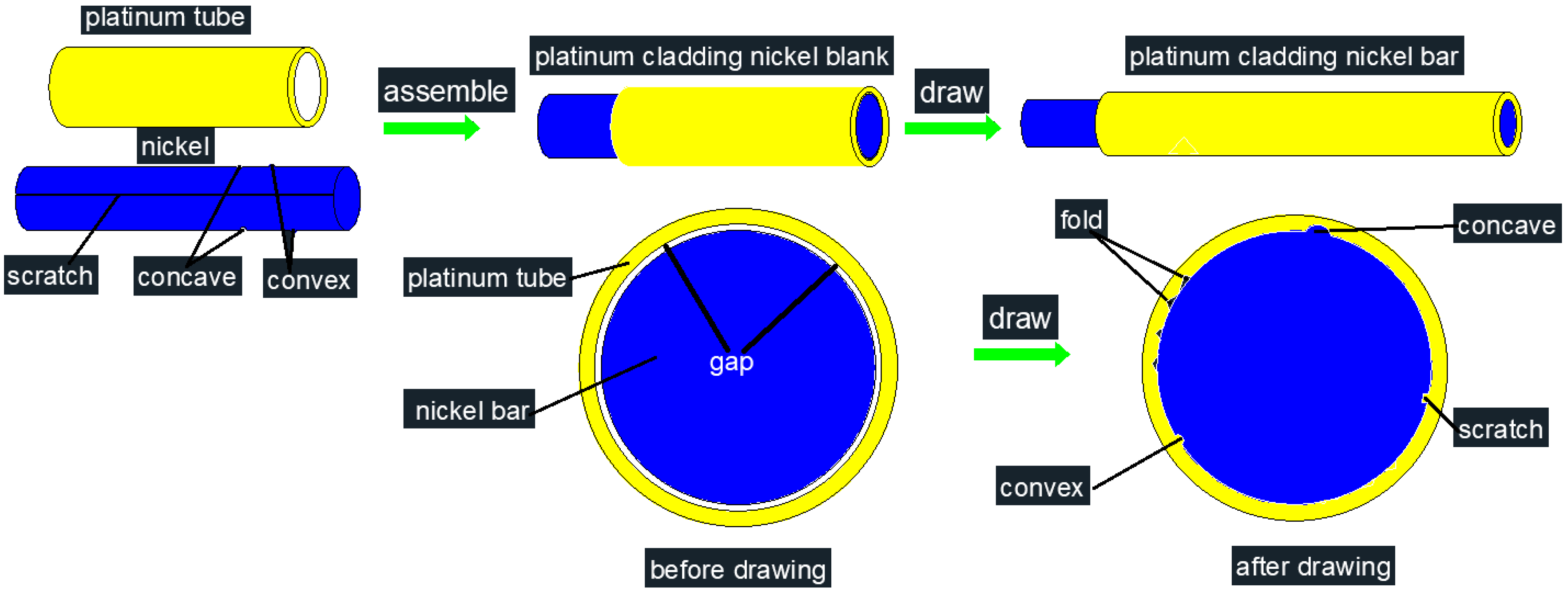
Figure 1 shows the schematic diagram of the cladding drawing process. First, the nickel rods and platinum tubes were cleaned using acetone. Second, the nickel rods were inserted into the two platinum tubes and aligned at one end. The aligned end was rolled to Φ 7.00–7.10 mm, with a length of approximately 6 cm, using a tip rolling machine. Two platinum-clad nickel composite blanks with outer diameters of 7.4 mm and 7.6 mm were then obtained, namely No1 and No2. Third, the first drawing step was performed using a chain drawing machine, followed by vacuum annealing at 600 °C for 1 h. The diameters of the calibrating straps of the drawing dies for No1 and No2 were Φ 7.32 mm and Φ 7.52 mm, respectively. Due to the large difference in mechanical properties between platinum and nickel, as well as the lack of metallurgical bonding between the platinum tube and nickel rod, the nickel rod did not deform; only the platinum tube was reduced in diameter and extended during the first drawing step. Therefore, after the first drawing step, the diameter of No1 was compressed to 7.32 mm, and the thickness of the platinum layer was 0.185 mm, whereas the diameter of No2 was compressed to 7.52 mm, and the thickness of the platinum layer was 0.285 mm. Fourth, several passes of drawing and annealing were performed. The drawing process was as follows: the single-pass deformation was 10–15%, and the cumulative deformation was 70–80%. The annealing process comprised vacuum annealing at 600 °C for 30 min. Finally, when the composite wire was drawn to a diameter of 0.2 mm, two sizes of platinum–nickel composite wire with platinum layer thicknesses of 5 μm (Sample 1) and 8 μm (Sample 2), respectively, were prepared.
The platinum-clad nickel composite wires with diameters of 0.2 mm were cut into short rods with a length of 100 mm. Oxidation experiments were then performed using a muffle furnace. First, the temperature of the muffle furnace was raised to the temperature required for the experiment and then the samples were placed into the muffle furnace for oxidation experiments at different temperatures (500 °C, 600 °C, 700 °C, and 800 °C) for different times (1 h, 2 h, and 3 h). When the oxidation time had elapsed, the samples were immediately removed from the furnace and cooled in air. The oxidized samples were examined using scanning electron microscopy (SEM) (Phenom-World BV, Eindhoven, The Netherlands) with an energy-dispersive X-ray (EDX) spectrometer attached.

3. Results

3.1. Raw Sample Analysis

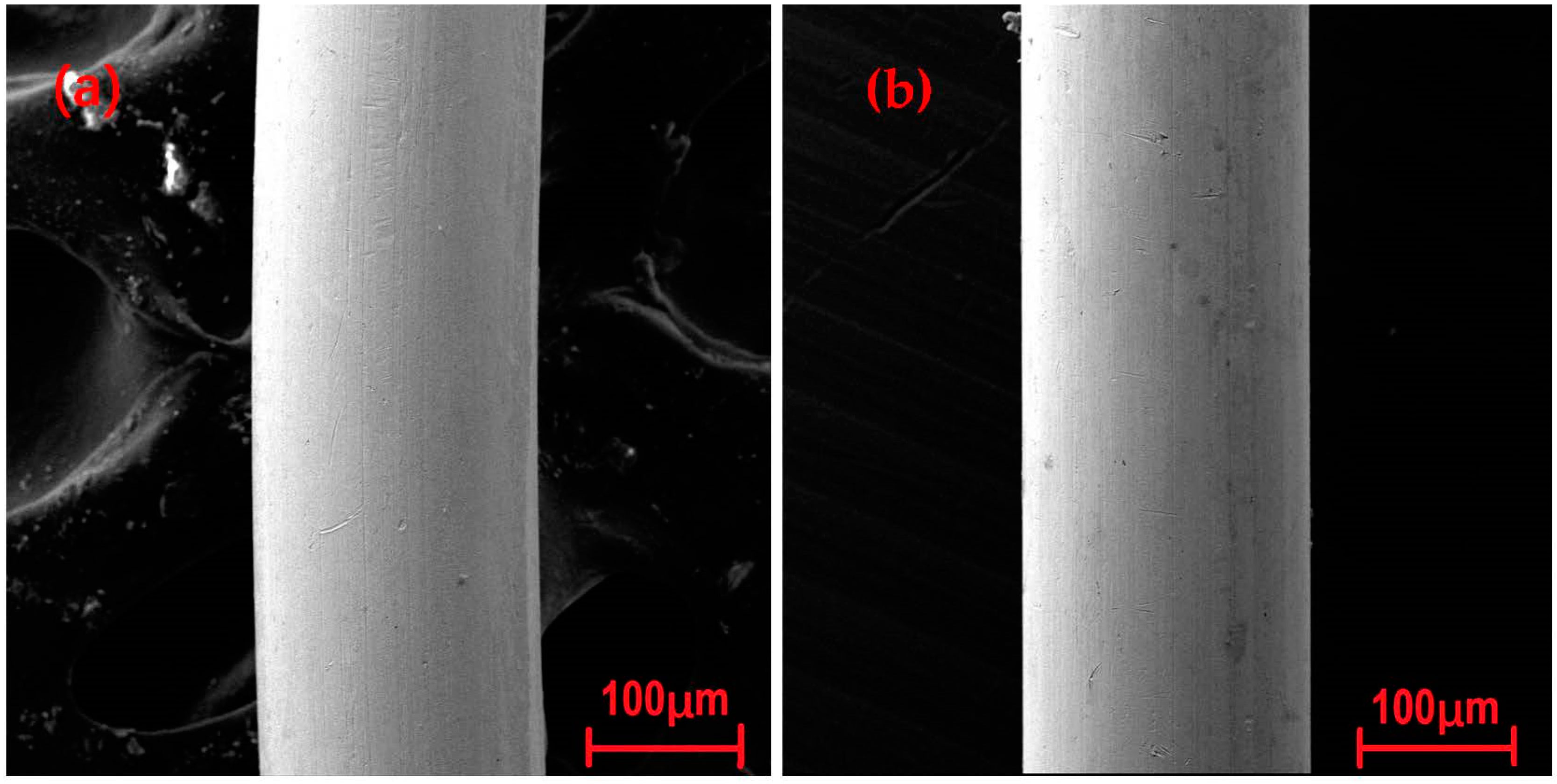
Figure 2 shows the surfaces of the samples before oxidation. As seen in Figure 2, the surface of the platinum cladding was smooth and intact, with no fractures or burrs. However, there were slight surface scratches, likely from the surface being inevitably scratched during processing, packaging, and preservation due to the platinum layer being too soft. Overall, it was feasible to prepare platinum–nickel composite wires by cladding drawing.
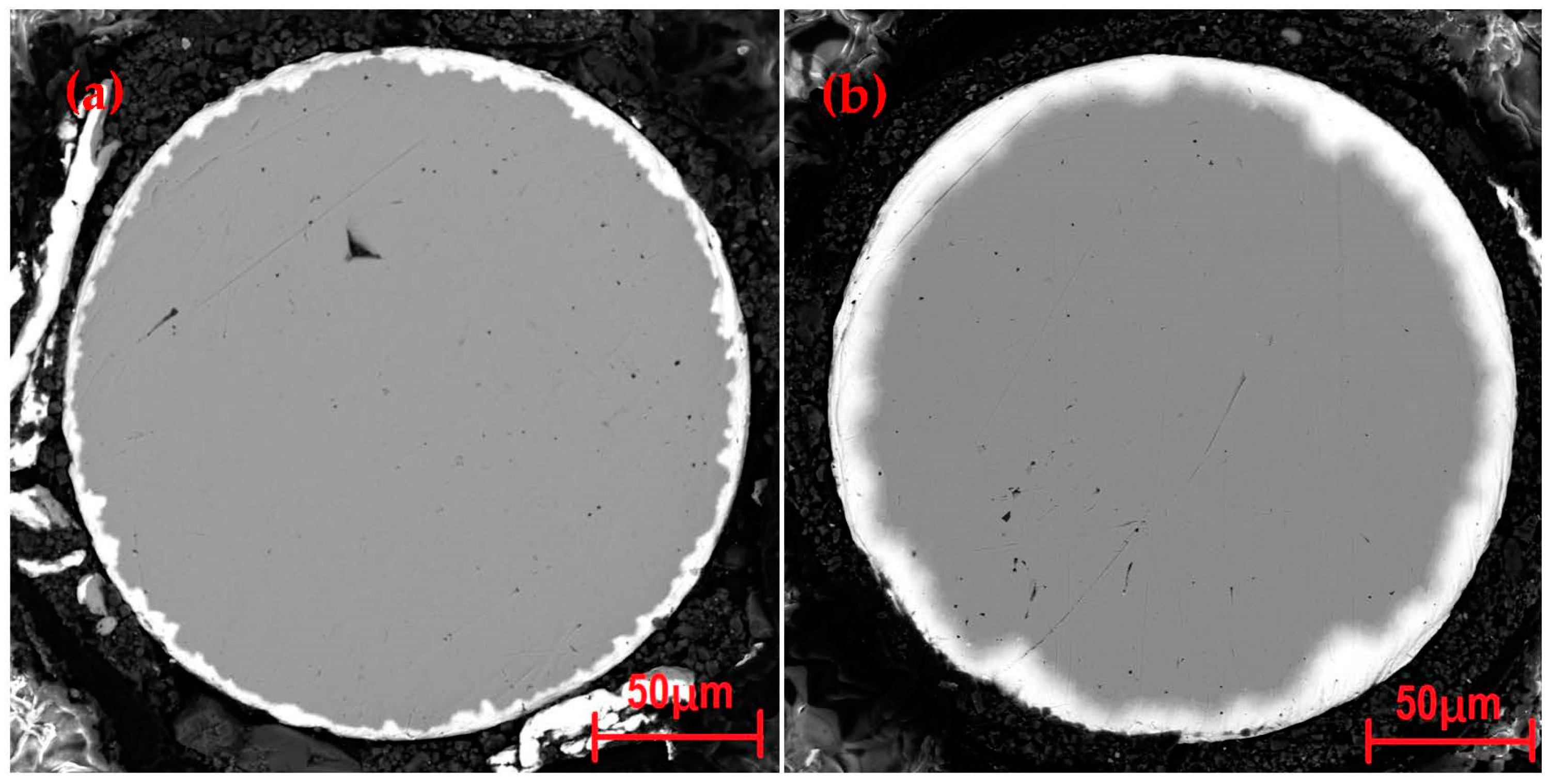
Figure 3 shows the cross-sectional views of the platinum-clad nickel composite wires before oxidation. The platinum layers were all completely covered on the surface of the nickel core wire, but the thickness of the platinum cover was not uniform and was undulating. The average platinum layer thickness of Sample 1 was 5 μm, with a deviation of 5.1 μm, as shown in Figure 3a; it was 3.5 μm at the thinnest point and 8.6 μm at the thickest point. The average platinum layer thickness of Sample 2 was 8 μm, with a deviation of 5.3 μm, as shown in Figure 3b; it was 5.5 μm at the thinnest point and 10.8 μm at the thickest point. The interface of Sample 1 had a pronounced jagged pattern; that of Sample 2 had a much gentler undulation.

3.2. Surface Morphology after Oxidation

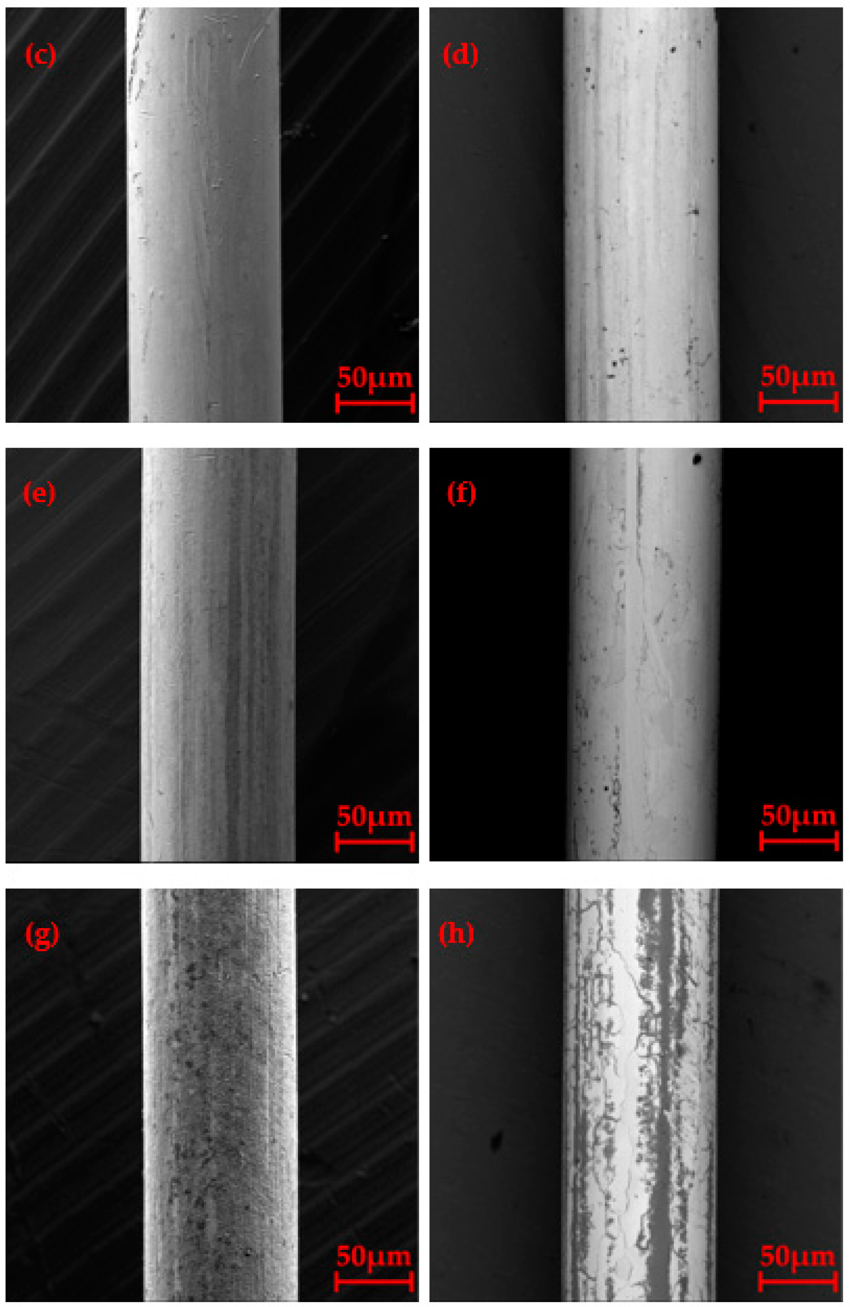
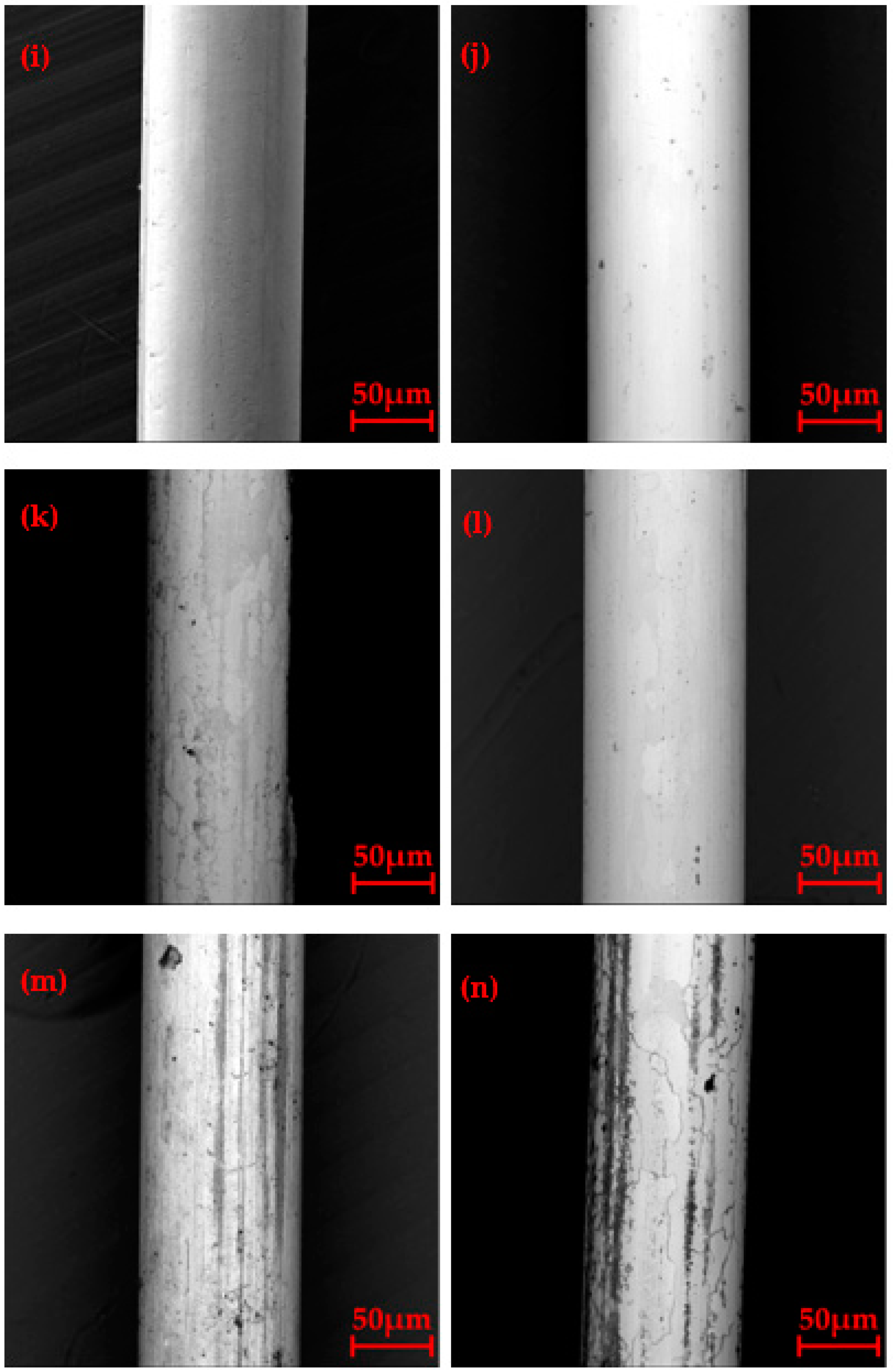
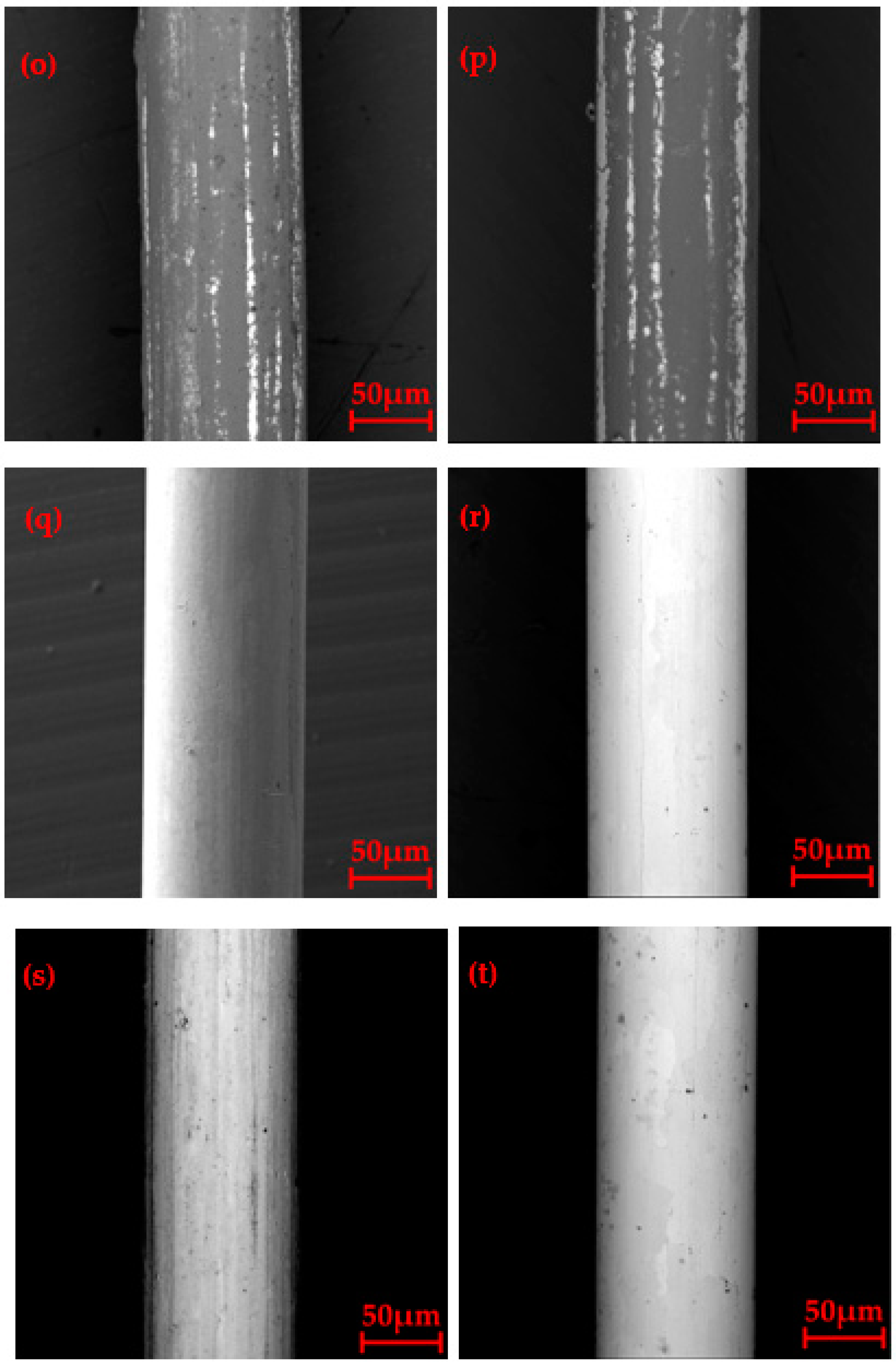
Figure 4 shows the surface morphologies of the platinum-clad nickel composite wires after oxidation. There was no change on the surface of the composite wires when oxidized at 500 °C for 1 h, 2 h, and 3 h, as shown in Figure 4a,b,i,j,q,r. When the oxidation treatment was performed at 600 °C, the platinum layer recrystallized, and there were obvious grain boundaries on the surface. However, with the increase in heat treatment time, the grains did not significantly grow, as shown in Figure 4c,d,k,l,s,t. This demonstrated that the platinum-clad nickel composite wire could be used for a short time (3 h) below 600 °C and would not oxidize or fail. When the oxidation treatment was performed at 700 °C, black streaks appeared along the axial direction; these gradually increased with an increase in the heat treatment time, as shown in Figure 4e,f,m,n,u,v. At the same oxidation time, the black streaks on the surface of the composite wire with a platinum layer of 5 μm were significantly more frequent than those of the 8 μm wire. With an increase in the heat treatment time, the grain boundaries of the surface platinum layer grains became significantly darker and coarser, as can be seen in Figure 4h,v. When the oxidation temperature exceeded 700 °C, the thickness of the platinum layer had little effect on the oxidation resistance and surface oxidation occurred, indicating that the platinum-clad nickel composite wire was not suitable for use at high temperatures (≥700 °C).

3.3. Surface Element Analysis

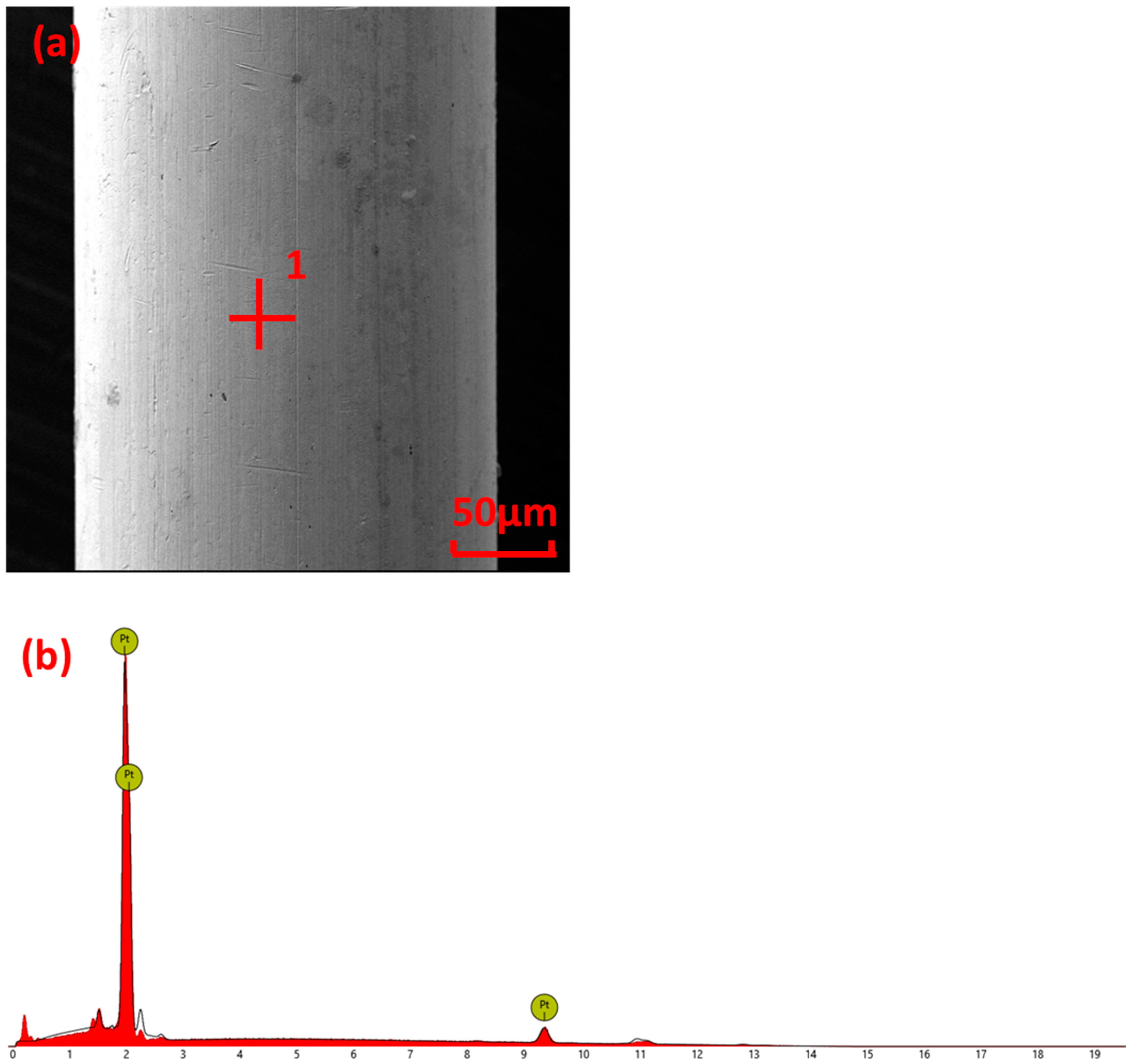
Figure 5 shows the surface morphology and energy spectrum analysis results of Sample 1 oxidized at 500 °C for 3 h. The surface of the composite wire was smooth and clean; this was the same as before oxidation, as shown in Figure 5a. Only the platinum without other elements was on the surface, as shown in Figure 5b, indicating that the platinum-clad nickel composite wire had good stability at 500 °C.
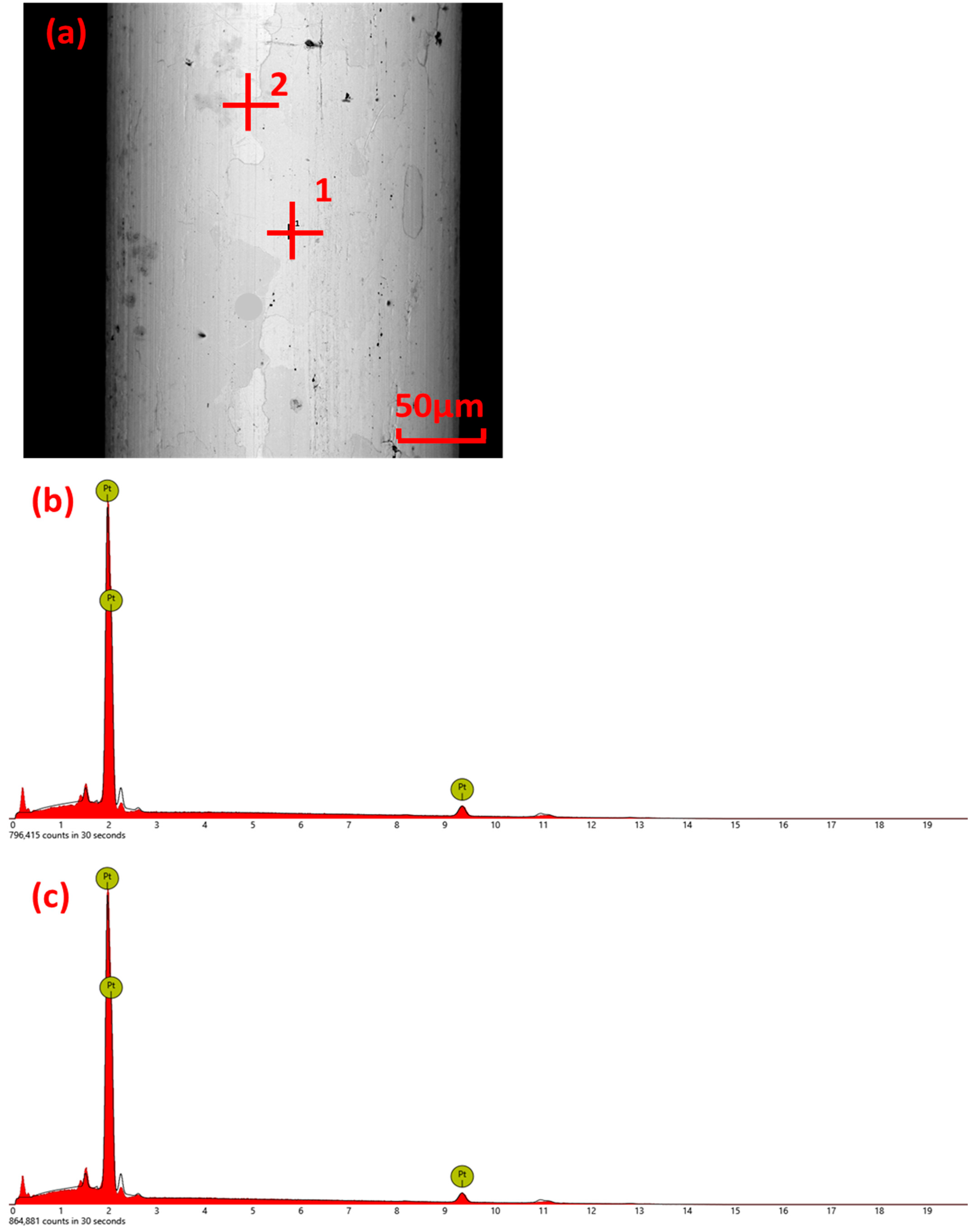
Figure 6 shows the surface morphology and energy spectrum analysis results of Sample 2 oxidized at 600 °C for 2 h. The platinum layer was completely recrystallized, and the grains were coarse. The grain boundaries were clearly visible on the surface, as shown in Figure 6a. Energy spectra were obtained inside the grain (Figure 6a) and at the grain boundaries (Figure 6c), both of which only had platinum elements. This indicated that the nickel had not diffused to the surface under this condition.
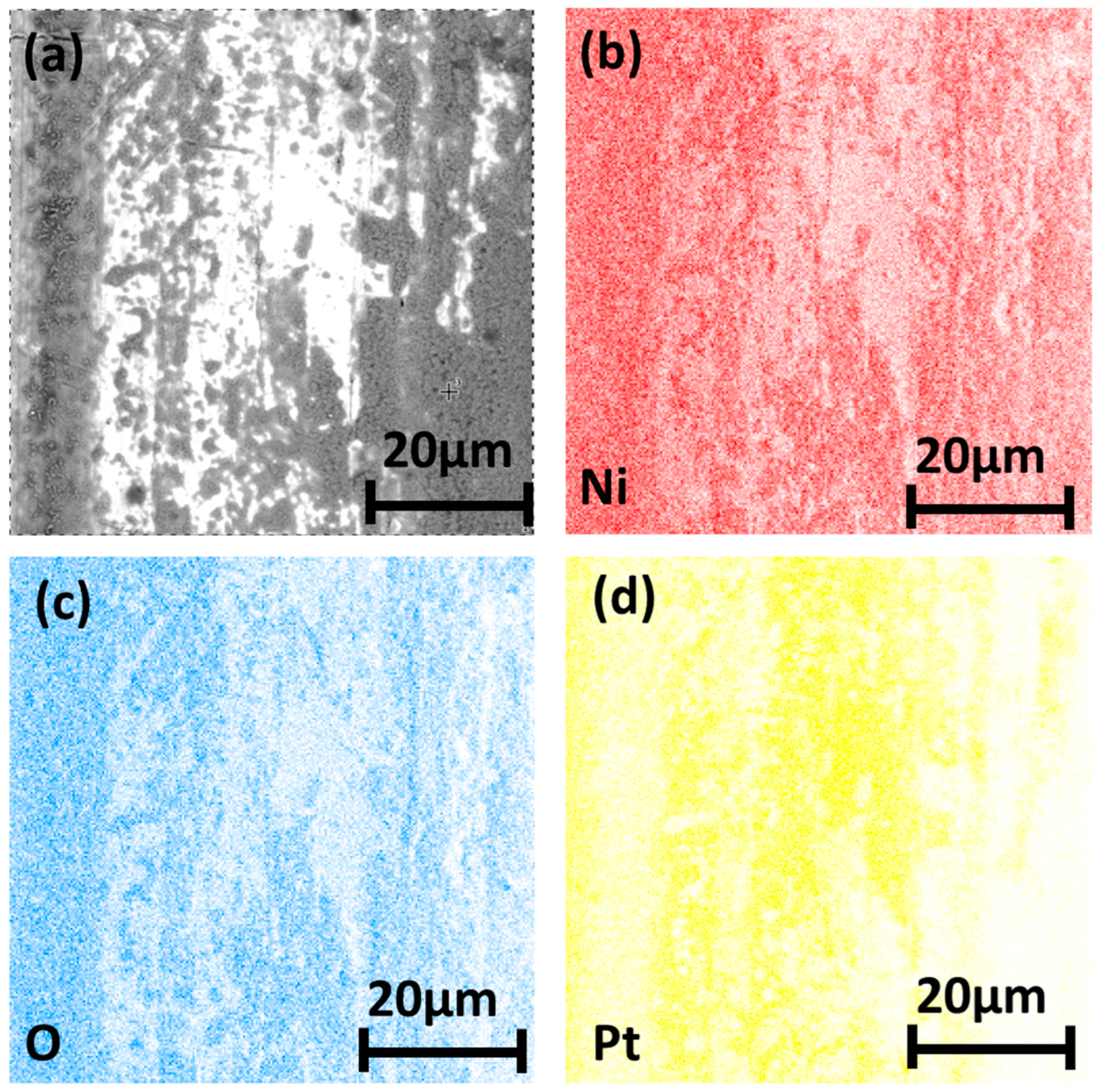
Figure 7 shows the element mapping analysis of Sample 1 oxidized at 700 °C for 3 h. Approximately 50% of the surface area of the composite wire was covered with black material, which was distributed in three states: strips, blocks, and dots. The black strip material was distributed along the axial direction, which was relatively rough, and many dotted particles were dispersed on it. The black dots were sporadically scattered in the white areas and were joined into small patches in places. The surface of the large black material had a porous structure. According to the element mapping analysis results shown in Figure 7b–d, nickel and oxygen elements appeared in the black area at the same time, indicating that the black material was an oxide of nickel. Nickel has three oxides, namely NiO, Ni3O4, and Ni2O3. Ni2O3 is stable only at low temperatures; when it is heated to 400~450 °C, it dissociates into Ni3O4. With a further increase in the temperature, it finally becomes NiO. The oxidation temperature of this sample was 700 °C; therefore, we ascertained that the black substance was NiO. Platinum could be found in the thinner oxide layer (strip oxide areas), but there was no platinum element distribution in the thicker oxide layer (block oxide areas).
Figure 8 shows the element mapping analysis of Sample 2 oxidized at 700 °C for 3 h. Cracks were present on the surface of the composite wire, and the morphology and distribution of the cracks were similar to the grain boundaries of the grains in Figure 4c,d,k,l,s,t. Therefore, we inferred that the cracks appeared at the grain boundaries of the platinum. There was also a large number of axial black stripes on the surface of the wire. The nickel and oxygen elements were distributed along the cracks on the surface of the wire, as shown in Figure 8b–d, indicating that the nickel had diffused to the surface through the grain boundaries and was oxidized to NiO. The black stripes were nickel and oxygen; this was because the thickness of the platinum layer was undulating. Nickel first diffused from the thinnest place of the platinum layer to the surface of the wire and was oxidized.

3.4. Microstructure of Longitudinal Sections

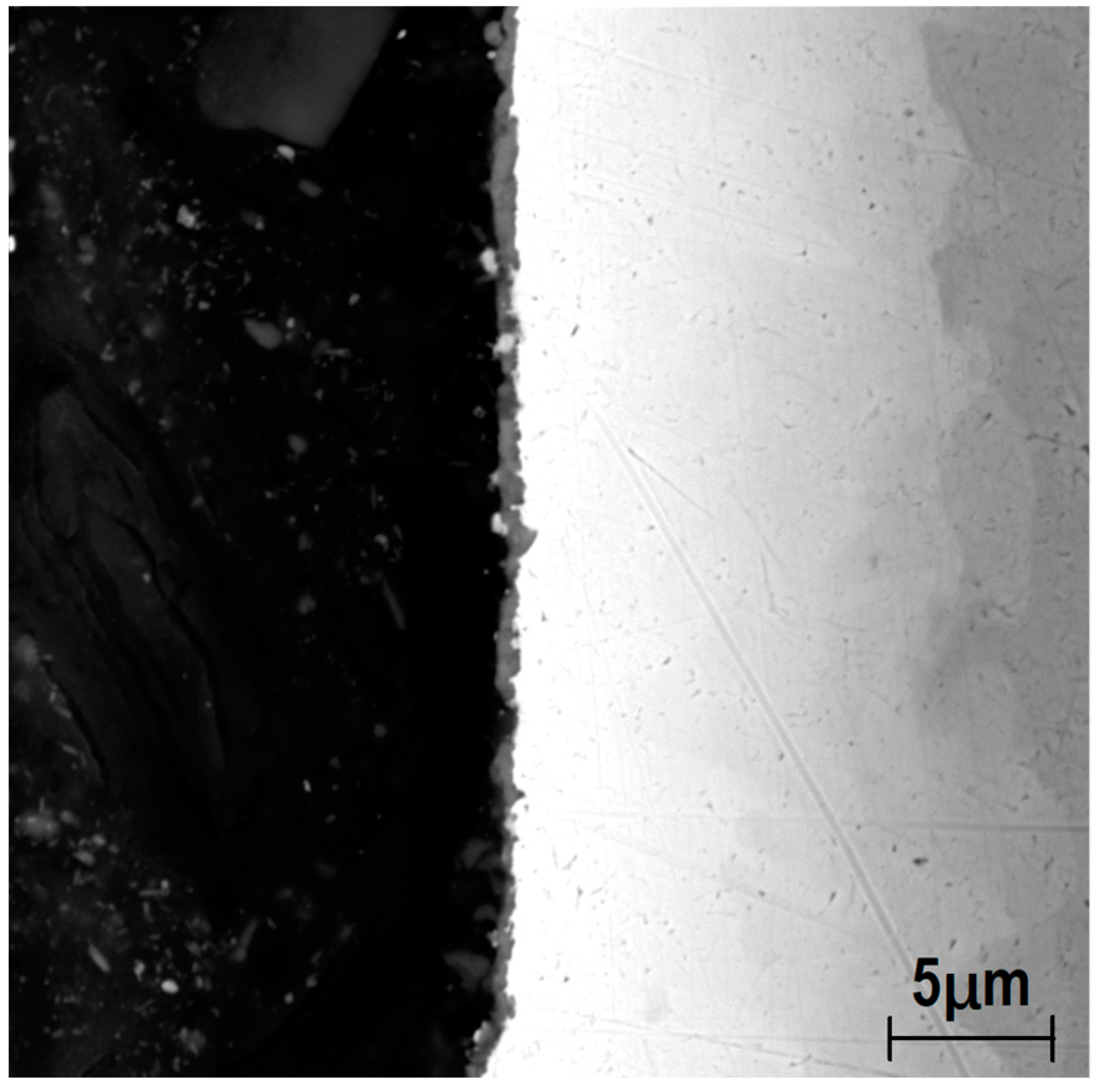
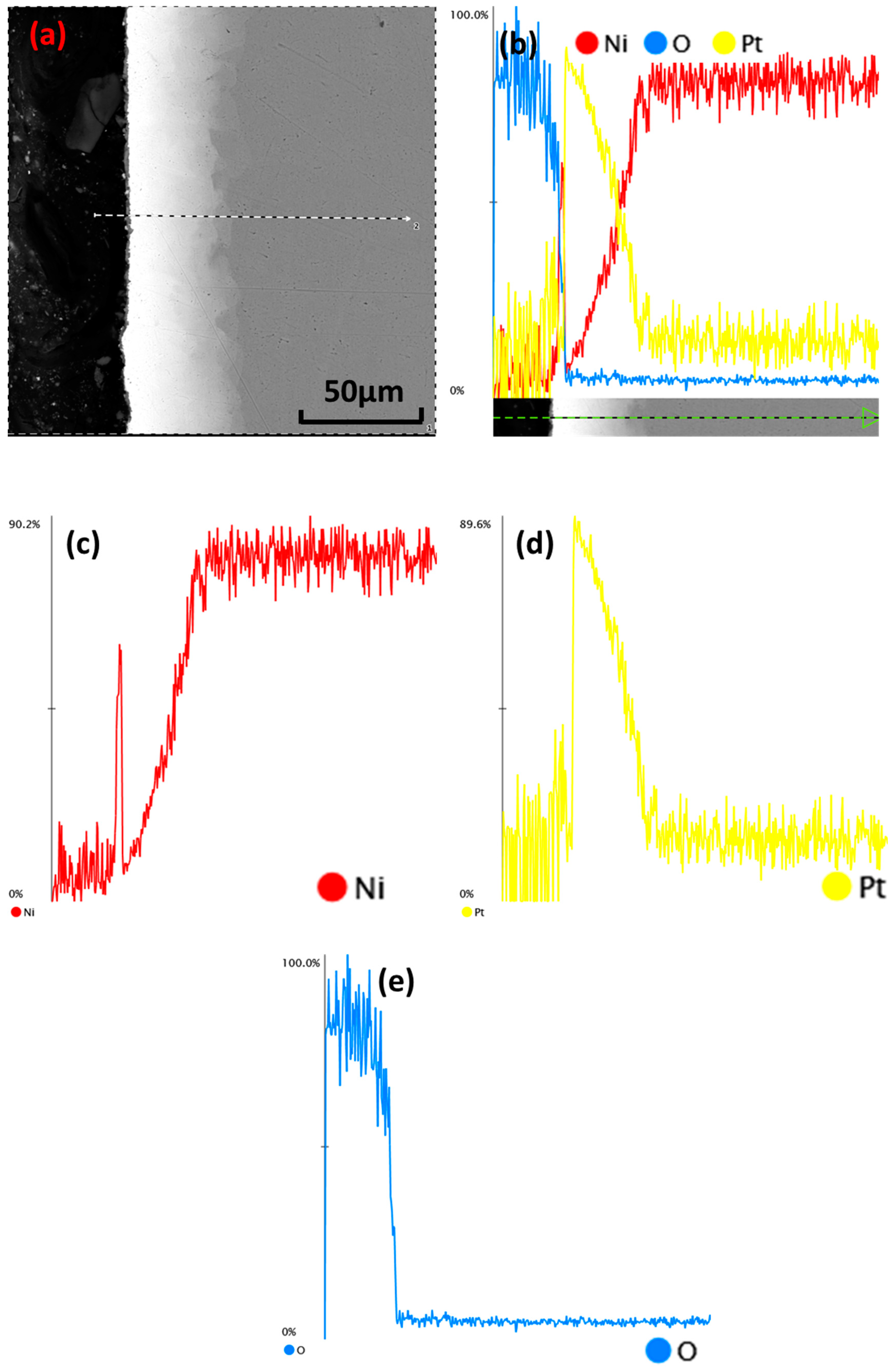
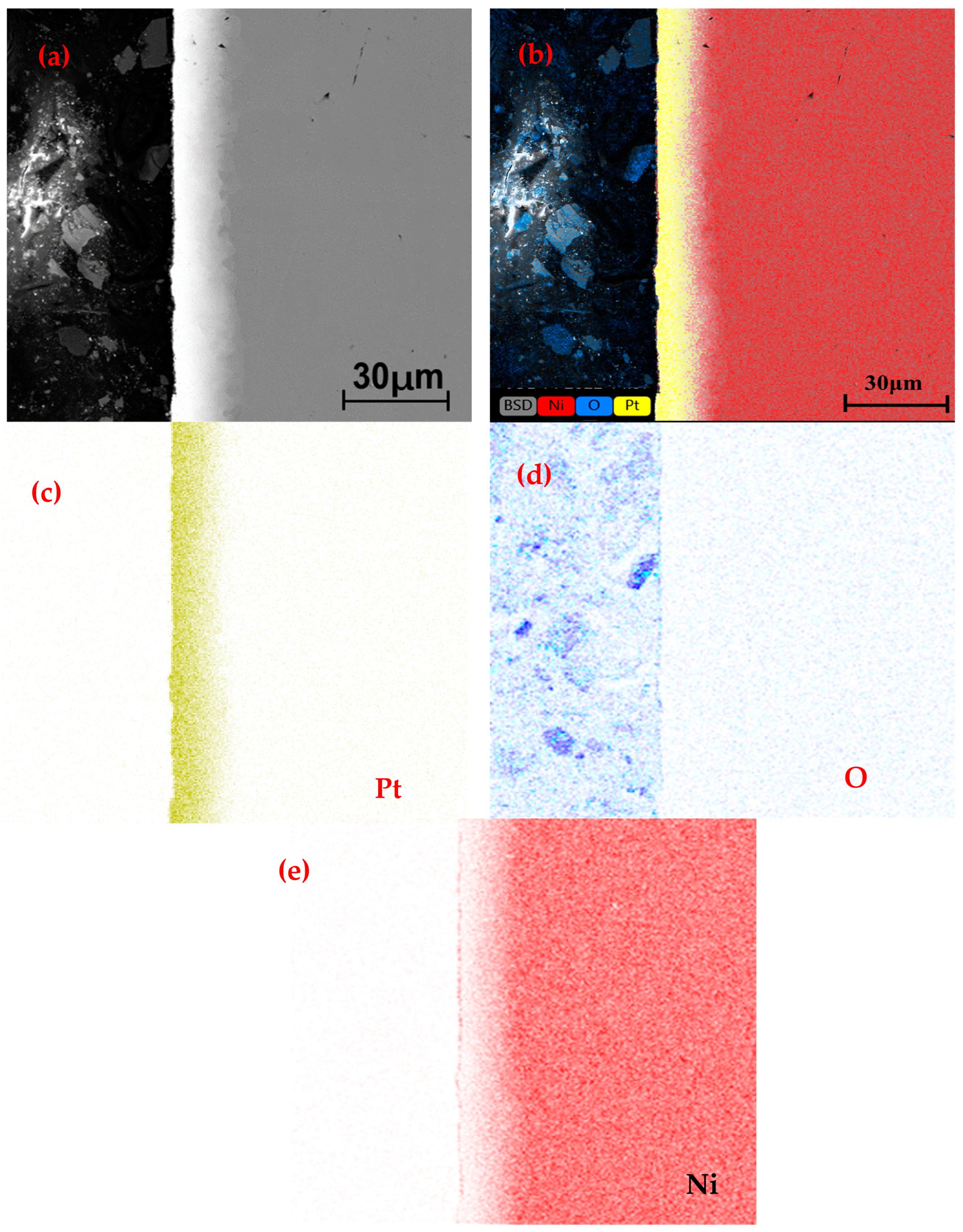
Figure 9 shows the microstructure of the longitudinal section of Sample 2 oxidized at 800 °C for 2 h. The outer surface of the platinum layer was covered by a layer of nickel oxide with a thickness of approximately 0.3 μm. The thickness of the oxide layer was uneven and discontinuous; in several places, it leaked out of the platinum layer, indicating that the oxide layer had local shedding. The interface between the platinum layer and the oxide layer was uneven and jagged. The thickness of the platinum layer ranged from 13 μm to 17 μm, which was much greater than the thickness of 5.5 μm to 10.8 μm before oxidation. This indicated that a severe mutual diffusion of platinum and nickel had occurred. The interface between the platinum layer and the nickel rod was clearly visible and uneven, but the serrations became rounded. SEM–EDS line scans of the interface were performed by EDS, as shown in Figure 10. There was a distribution of nickel elements on the surface of the composite wire, whereas the platinum did not significantly change. This indicated that the covering layer comprised nickel oxides. Nickel had diffused to the outer surface of the platinum layer, and the platinum layer had become a platinum–nickel alloy. The content of nickel linearly increased from the outer surface of the wire to the interface. The nickel content at the interface between the coating and the nickel core wire was 100%. The platinum content linearly decreased from the outer surface of the wire to the interface until it was finally 0%. To more accurately understand the distribution of nickel and oxygen in the composite wire, an SEM–EDS plane scan of the interface was obtained, as shown in Figure 11. The outer layer of the composite wire had an oxide layer of nickel, which was consistent with the line scan results (Figure 11). In the platinum–nickel alloy cladding, there were no agglomerates of nickel and oxygen. This indicated that oxygen had not penetrated into the interior of the alloy but had only reacted with the nickel that had diffused to the surface and that the oxidation reaction only occurred at the surface of the wire. No enrichment of nickel at the grain boundaries was found in the cladding, and no Kirkendall holes were found, indicating that the interdiffusion of the platinum and nickel was uniform and slow.

4. Discussion

4.1. The Formation Mechanism of Serrations at the Interface

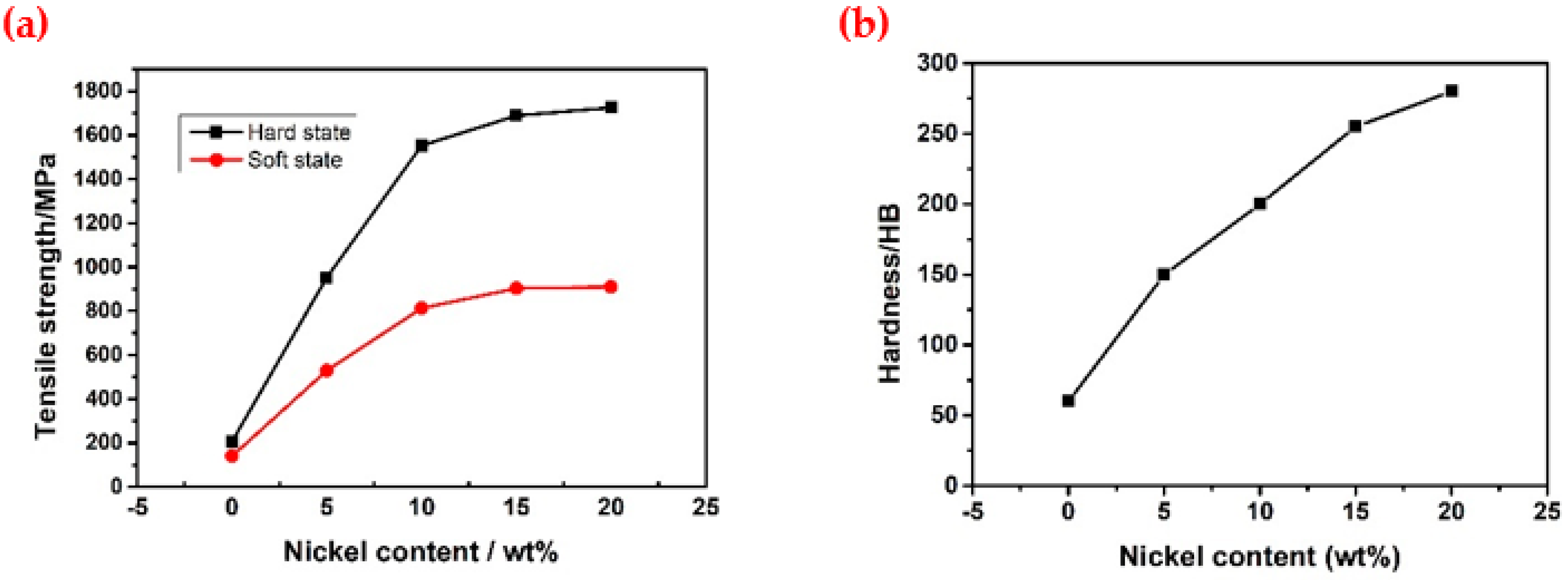
From the cross-sectional metallography of the original sample, it could be seen that the interface bond between the platinum cladding and the nickel wire was serrated, resulting in an uneven cladding thickness that would seriously affect the high-temperature service life of the platinum–nickel composite wire. Thus, an analysis of the formation mechanism of the serrations was essential. There were two reasons for the formation of serrations: (1) The serrations were produced during the first step of the drawing process. The composite wire was prepared by the cladding drawing method. The diagram of the first step of the drawing process to produce the serrations is shown in Figure 12. To enable the nickel bar to be smoothly inserted into the platinum tube, the outer diameter of the nickel bar had to be smaller than the inner diameter of the platinum tube. During the first step of drawing, the nickel bar was not deformed; only the platinum tube was deformed. The reduction in the wall thickness and the diameter of the platinum tube occurred at the same time; thus, folds may have been produced on its inner wall due to the uncoordinated flow of metal in various places, resulting in an uneven wall thickness and jaggedness. There were inevitable concave and convex scratches on the surface of the nickel bar and on the inner wall of the platinum tube. During the first step of drawing, the inner wall of the platinum tube reverse-copied the defects of the nickel bar due to the low hardness and good plasticity of the platinum, which also led to an uneven thickness. (2) The serrations were produced during the drawing and annealing process. After the first step of drawing to obtain a composite bar billet, it was necessary to undertake several annealing and drawing processes to obtain the product. During annealing, platinum–nickel alloy layers with different thicknesses and compositions were formed due to the different rates of mutual diffusion of the platinum and nickel at different places. The variation curves of the mechanical properties of platinum–nickel alloys with different nickel contents obtained from the literature [1] are shown in Figure 13. Although the literature only provides data on the mechanical properties of platinum–nickel alloys with a nickel content of 0–20%, we observed that as the nickel content increased, both the hardness and tensile strength rose. Thus, the platinum–nickel alloys with different compositions had completely different mechanical properties, leading to uncoordinated deformation during the drawing process and the production of serrations. These two reasons led to uneven serrations and cladding thicknesses.

4.2. Diffusion and Oxidation Behavior of Nickel

As shown in Figure 7 and Figure 8, there were two main diffusion paths of nickel, namely grain boundary diffusion and bulk diffusion. Figure 6 demonstrates that the platinum did not recrystallize at 500 °C. Therefore, at low temperatures (500 °C), the diffusion pathway for nickel was mainly bulk diffusion. When the oxidation temperature reached 600 °C and above, the platinum recrystallized, and there were clearly visible grain boundaries on the surface of the platinum cladding, as shown in Figure 7. At this oxidation temperature (≥600 °C), the diffusion pathways for nickel were grain boundary diffusion and bulk diffusion. As shown in Figure 10, there was no distribution of oxygen inside the cladding, indicating that the nickel had diffused through the grain boundaries and bulk to the surface of the composite wire and had then reacted with oxygen to produce NiO, which demonstrated typical selective oxidation. The approximate relationship between the diffusion distance ( x ) and the diffusion coefficient (D) and time (t) can be expressed as follows:
x 2 = D t
At the same time, the diffusion coefficient is strongly dependent on temperature, and its relationship with temperature can be expressed by the Arrhenius formula:
D = D 0 exp ( Q R T )
where D 0 is the diffusion constant, R is the molar gas constant (8.314 J/(mol·K)), Q is the diffusion activation energy, and T is the absolute temperature. We substituted Equation (2) into Equation (1) to obtain the following equation:
x 2 = D 0 exp ( Q R T ) t
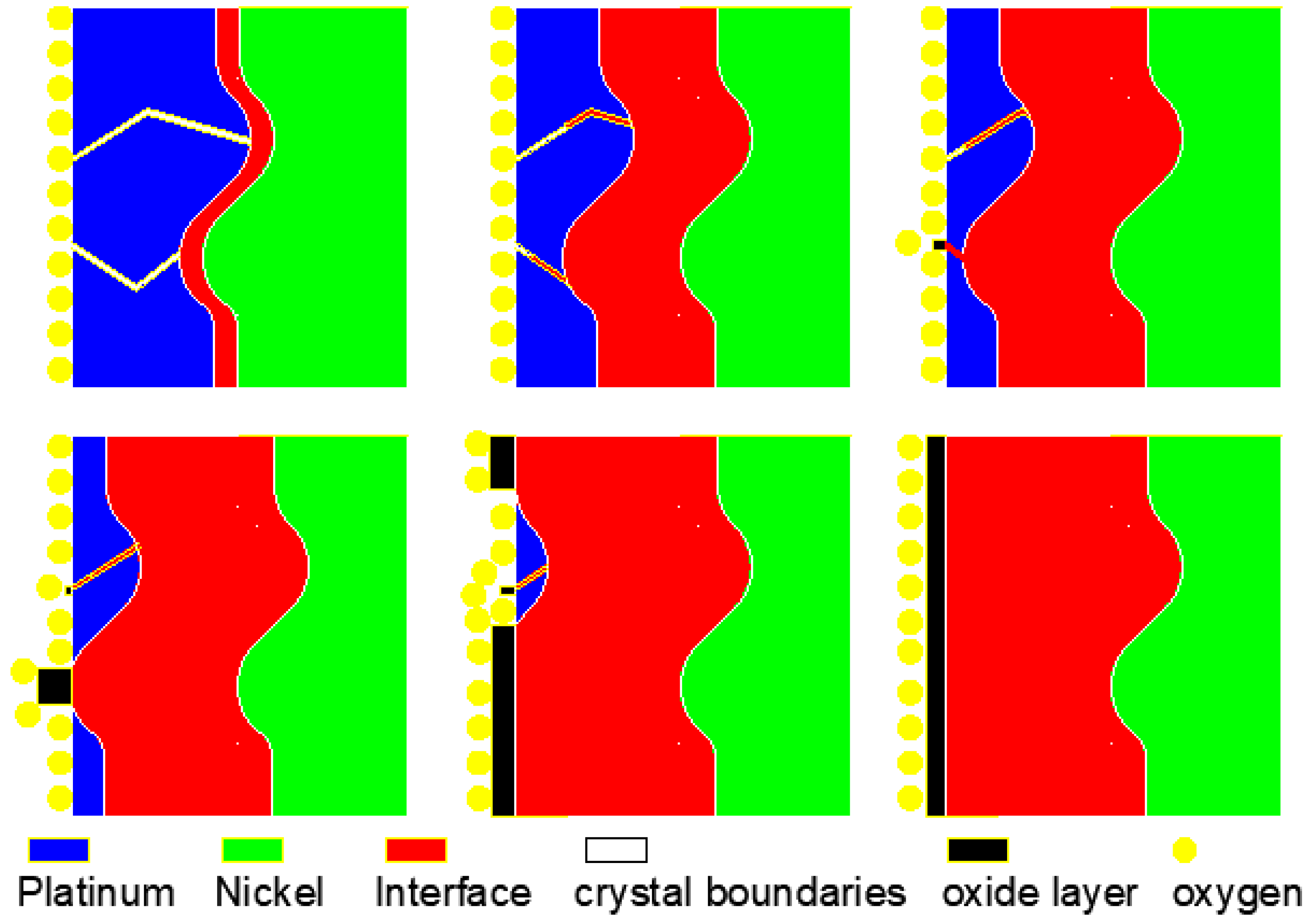
As can be seen from Equation (3), the square of the diffusion distance (x) was exponentially related to the absolute temperature (T) for the same oxidation time; the higher the oxidation temperature, the greater the diffusion distance of the nickel. The nickel did not diffuse to the surface and was not oxidized at a lower temperature (≤600 °C) for 3 h, whereas the nickel did diffuse to the surface and was oxidized at a higher temperature (≥700 °C) for 1 h, indicating that the platinum-clad nickel composite wire could be used at 500 °C and 600 °C for a short time. Determining whether it could be used for a longer time would require verification with a long-term oxidation experiment, which was not covered in this paper. Figure 14 shows a schematic diagram of the diffusion and oxidation process of the nickel. The grain boundaries could be considered to be defects in the crystal; the distortions created by the defects made it easier for the atoms to migrate than it would have been within an intact crystal. Thus, the rate of diffusion of nickel in the grain boundaries was greater than the rate of diffusion of nickel within the crystal. Under the conditions of the same platinum layer thickness and oxidation temperature, the nickel diffused through the grain boundaries to the surface in less time than through the bulk; therefore, the composite wire was oxidized earlier at the grain boundaries of the surface. Under the conditions of the same oxidation temperature, the thinner the platinum layer, the smaller the diffusion distance and the shorter the time for the nickel to diffuse to the surface. Due to the jagged interface and the uneven thickness of the platinum layer of the sample, the thinnest areas of the platinum layer were the first to be oxidized. Therefore, the service life of the composite wire was strongly dependent on the service temperature and the minimum platinum layer thickness.
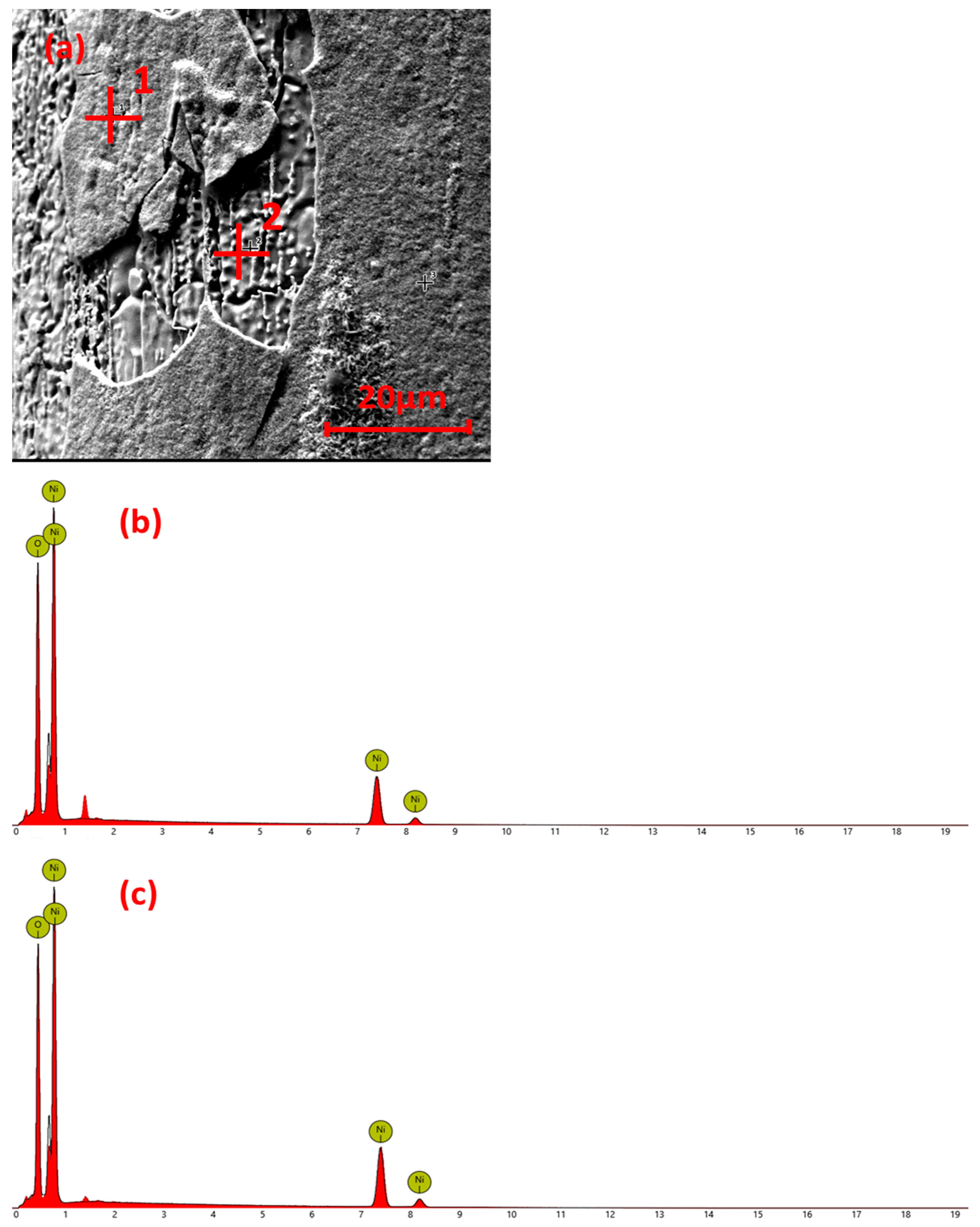
As a NiO layer is a porous structure, it cannot form a dense oxide film and cannot prevent the oxidation of nickel. With the increase in oxidation time, the thickness of the oxide layer gradually increased. Due to the different expansion coefficients of the oxide layer and the metal matrix, when the oxide layer grew to a certain energy thickness it was partially exfoliated, as shown in Figure 15. An energy spectrum analysis was performed for both the non-dislodged part (point 1) and the dislodged part (point 2) as shown in Figure 15b,c, respectively, both comprised nickel and oxygen.

5. Conclusions

(1) The interface between the platinum cladding and the nickel core wire was serrated, and the thickness of the platinum cladding was uneven.
(2) The diffusion rate was low at a low temperature (500 °C). When the temperature reached 600 °C and above, the diffusion paths of the nickel were grain boundary diffusion and bulk diffusion; the higher the temperature, the greater the diffusion rate. When the temperature reached 700 °C and above, the nickel diffused to the surface of the composite wire and immediately reacted with oxygen to form a NiO layer, which was typical of selective oxidation. The composite wire could be used for a short time below 600 °C. Determining whether it could be used for a long time would require verification with a long-term aging experiment, which was not a part of this paper.
(3) The service life of the composite wire was strongly dependent on the service temperature and the minimum platinum layer thickness.

Author Contributions

Conceptualization, Y.C., X.C. and M.X.; methodology, Y.C. and M.X.; software, Y.C., J.H. and S.W.; validation, Y.Y., J.F. and A.L.; formal analysis, Y.C. and S.W.; resources, Y.C., X.C. and M.X.; data curation, Y.C. and J.F.; writing—original draft preparation, Y.C. and J.F.; investigation, Y.Y. and A.L.; writing—review and editing, Y.C.; visualization, Y.C., J.H. and S.Z.; supervision, M.X.; project administration, Y.C. and J.H.; funding acquisition, Y.C. All authors have read and agreed to the published version of the manuscript.

Funding

This research was funded by the Innovation Team Project of Yunnan Province (202105AE160027), the Plan Project of Yunnan Precious Metals Laboratory Science and Technology (YPML-2022050228), and the Rare and Precious Metals Material Genetic Engineering Project of Yunnan Province (202102AB080019-1).

Data Availability Statement

The data are available on request from the corresponding authors.

Conflicts of Interest

The authors declare no conflict of interest.

References

  1. Chauhan, A.K.; Tiwari, S.; Singh, S.; Singh, J.; Wadhwa, M. Experimental study of thermal annealing effects on evaporated platinum thin film with various substrate configurations. Microsyst. Technol. 2023, 29, 107–114. [Google Scholar] [CrossRef]
  2. Zhang, B.T.; Chen, X.; Yuan, J.F.; Zhu, H.D. Research on Temperature Measurement Technology of Platinum Film Thermistor. J. Phys. Conf. Ser. 2021, 1907, 012038. [Google Scholar] [CrossRef]
  3. Golub, V.V.; Zhilin, Y.V.; Rylov, S.A. A Platinum Thin-Film Resistance Thermometer. Instrum. Exp. Tech. 2018, 61, 138–145. [Google Scholar] [CrossRef]
  4. Wang, D.X.; Jiang, X.L.; Yang, Y.C.; Pi, Q.Q.; Liu, X. Development of high precision platinum thin film thermistors for wide temperature range. Sens. Microsyst. 2022, 41, 81–84. [Google Scholar]
  5. Lv, W.M.; Wang, Y.Q.; Shi, W.H.; Cheng, W.; Huang, R.; Zhong, R.F.; Zeng, Z.M.; Fan, Y.M.; Zhang, B.S. Role of micro-nano fabrication process on the temperature coefficient of resistance of platinum thin films resistance temperature detector. Mater. Lett. 2022, 309, 131313. [Google Scholar] [CrossRef]
  6. Han, J.; Cheng, P.; Wang, H.; Zhang, C.C.; Zhang, J.B.; Wang, Y.; Duan, L.; Ding, G.F. MEMS-based Pt film temperature sensor on an alumina substrate. Mater. Lett. 2014, 125, 224–226. [Google Scholar] [CrossRef]
  7. Mei, X.X.; Zhang, X.N.; Zhang, L.S.; Li, N.; Zhang, P.; Guo, Y.T.; Koval, N.N. Enhancing the Oxidation Resistance of NiCrAlY Bond Coat by High-Current Pulsed Electron Beam Irradiation. Coatings 2021, 11, 912. [Google Scholar] [CrossRef]
  8. Gurtaran, M.; Zhang, Z.X.; Li, X.Y.; Dong, H.S. High-Temperature Oxidation Behaviour of CrSi Coatings on 316 Austenitic Stainless Steel. Materials 2023, 16, 3533. [Google Scholar] [CrossRef]
  9. Fan, Q.X.; Yu, H.J.; Wang, T.Q.; Liu, Y.M. Microstructure and Oxidation Resistance of a Si Doped Platinum Modified Aluminide Coating Deposited on a Single Crystal Superalloy. Coatings 2018, 8, 264. [Google Scholar] [CrossRef] [Green Version]
  10. Xu, Z.L.; Wang, F.T.; Peng, S.T.; Liu, W.W.; Guo, J.N. Effects of Process Parameters on Microstructure and High-Temperature Oxidation Resistance of Laser-Clad IN718 Coating on Cr5Mo Steel. Coatings 2023, 13, 197. [Google Scholar] [CrossRef]
  11. Lin, X.H.; Zhang, G.J.; Li, L.P.; Liu, Y.; Li, Y.C.; Li, B.; Zhang, W. Effect of Ti and Si Additions on Microstructure, Fracture Toughness and Oxidation Resistance of Nb-Mo5SiB2 Composite. JOM 2021, 73, 3476–3485. [Google Scholar] [CrossRef]
  12. Zhang, S.T.; Ouyang, P.X.; Yan, H.J.; Si, L.N. Study on Microstructure and Oxidation Resistance Mechanism of Y-Modified NiCrAlY Coating Prepared by Pack Cementation. Coatings 2023, 13, 63. [Google Scholar] [CrossRef]
  13. Kim, J.; Pyeon, J.; Kim, B.G.; Khadaa, T.; Choi, H.; Zhe, L.; Dube, T.; Zhang, J.; Yang, B.; Jung, Y.; et al. Oxidation Behavior of NiCoCrAlY Coatings Deposited by Vacuum Plasma Spraying and High-Velocity Oxygen Fuel Processes. Coatings 2023, 13, 319. [Google Scholar] [CrossRef]
  14. Zhu, L.; Wang, X.H.; Ren, X.R.; Kang, X.Q.; Akhtar, F.; Feng, P.Z. Preparation and high-temperature oxidation resistance of multilayer MoSi2/MoB coating by spent MoSi2-based materials. J. Am. Ceram. Soc. 2021, 104, 3682–3694. [Google Scholar] [CrossRef]
  15. Huang, L.; Zhou, Z.H.; Yang, L.L.; Qiao, Y.X. The Oxidation Properties of a NiCrAlY Coating Fabricated by Arc Ion Plating. Coatings 2023, 13, 22. [Google Scholar] [CrossRef]
  16. Pan, Y.L.; Zhang, Z.D.; Wang, D.Y.; Guo, H.; Shi, Q.Y.; Lu, T.C. Sol–Gel-Derived Ni3Al Coating on Nickel Alloy for Oxidation Resistance in Supercritical Water Environments. Materials 2022, 15, 6566. [Google Scholar] [CrossRef] [PubMed]
  17. Yang, Y.K.; Yan, X.F.; Huan, C.H.; Bai, X.P. Manufacturing of Platinum-Nickel 30/70Compound Wires. Electrotech. Mater. 2006, 1, 6–9+13. [Google Scholar]
  18. Huang, B.F.; Yuan, H.M.; Luo, R.X. The Diffusion behaviour of Cu and Fe in Pt anode composite layer. Rare Met. Mater. Eng. 1992, 21, 67–71. [Google Scholar]
  19. Gelfond, N.V.; Krisyk, V.V.; Dorovskikh, S.I.; Kal’nyi, D.B.; Maksimovskii, E.A.; Shubin, Y.V.; Trubin, S.V.; Morozova, N.B. Structure of platinum coatings obtained by chemical vapor deposition. J. Struct. Chem. 2015, 56, 1215–1219. [Google Scholar] [CrossRef]
  20. Rooney, D.; Negrotti, D.; Byassee, T.; Macero, D.; Chaiken, J.; Vastag, B. Use of Laser-Directed Chemical Vapor Deposition to Fabricate Durable, Optically Transparent, Platinum Thin Film Electrodes. J. Electrochem. Soc. 2019, 137, 1162. [Google Scholar] [CrossRef]
  21. Arenas, L.F.; León, C.P.D.; Boardman, R.P.; Walsh, F.C. Characterisation of platinum electrodeposits on a titanium micromesh stack in a rectangular channel flow cell. Electrochim. Acta 2017, 247, 994–1005. [Google Scholar] [CrossRef] [Green Version]
  22. Bai, M.W.; Chen, Y.; Sun, Y.L.; Xiao, P. Mitigation of Platinum Depletion in Platinum Diffused Single Phase Bond Coat on CMSX-4 Superalloy. Coatings 2021, 11, 669. [Google Scholar] [CrossRef]
  23. Guan, J.Q.; Chen, Q.; Teng, H.T.; He, X. Preparation of catalytic platinum electrode paste for oxygen sensors and measurement of its electrical properties. Precious Met. 2017, 38 (Suppl. S1), 149–152. [Google Scholar]
  24. Xia, F.; Qian, X.L.; Yang, X.; Liu, G.K.; Sun, Y.Q. Process of fabricate Pt electrode in ZrO2 oxygen sensor. J. Sens. Sens. Technol. 2000, 19, 7–8+10. [Google Scholar]
  25. Zhang, S.H. Preparation and Performance of CVD Pure Tungsten Antioxidant Platinum Coatings. Ph.D. Thesis, Kunming University of Technology, Kunming, China, 2021. [Google Scholar]
  26. Igumenov, I.K.; Gelfond, N.V.; Galkin, P.S.; Morozova, N.B.; Fedotova, N.E.; Zharkova, G.I.; Shipachev, V.I.; Reznikova, E.F.; Ryabtsev, A.D.; Kotsupalo, N.P.; et al. Corrosion testing of platinum metals CVD coated titanium anodes in seawater-simulated solutions. Desalination 2001, 136, 273–280. [Google Scholar] [CrossRef]
  27. Touni, A.; Liu, X.; Kang, X.L.; Papoulia, C.; Pavlidou, E.; Lambropoulou, D.; Tsampas, M.N.; Chatzitakis, A.; Sotiropoulos, S. Methanol Oxidation at Platinum Coated Black Titania Nanotubes and Titanium Felt Electrodes. Molecules 2022, 27, 6382. [Google Scholar] [CrossRef] [PubMed]
Figure 1. Schematic diagram of the cladding drawing process.
Metals 13 01264 g001
Figure 2. Surface states before oxidation: (a) Sample 1; (b) Sample 2.
Metals 13 01264 g002
Figure 3. Cross-sectional view of platinum-clad nickel composite wires before oxidation: (a) Sample 1; (b) Sample 2.
Metals 13 01264 g003
Figure 4. Surface morphologies of platinum-clad nickel composite wires after oxidation: (a) Sample 1 oxidized at 500 °C for 1 h; (b) Sample 2 oxidized at 500 °C for 1 h; (c) Sample 1 oxidized at 600 °C for 1 h; (d) Sample 2 oxidized at 600 °C for 1 h; (e) Sample 1 oxidized at 700 °C for 1 h; (f) Sample 2 oxidized at 700 °C for 1 h; (g) Sample 1 oxidized at 800 °C for 1 h; (h) Sample 2 oxidized at 800 °C for 1 h; (i) Sample 1 oxidized at 500 °C for 2 h; (j) Sample 2 oxidized at 500 °C for 2 h; (k) Sample 1 oxidized at 600 °C for 2 h; (l) Sample 2 oxidized at 600 °C for 2h; (m) Sample 1 oxidized at 700 °C for 2 h; (n) Sample 2 oxidized at 700 °C for 2 h; (o) Sample 1 oxidized at 800 °C for 2 h; (p) Sample 2 oxidized at 800 °C for 2 h; (q) Sample 1 oxidized at 500 °C for 3 h;(r) Sample 2 oxidized at 500 °C for 3 h; (s) Sample 1 oxidized at 600 °C for 3 h; (t) Sample 2 oxidized at 600 °C for 3 h; (u) Sample 1 oxidized at 700 °C for 3 h; (v) Sample 2 oxidized at 700 °C for 3 h; (w) Sample 1 oxidized at 800 °C for 3 h; (x) Sample 2 oxidized at 800 °C for 3 h.
Metals 13 01264 g004aMetals 13 01264 g004bMetals 13 01264 g004cMetals 13 01264 g004dMetals 13 01264 g004e
Figure 5. Surface morphology and energy spectrum analysis results of Sample 1 oxidized at 500 °C for 3 h: (a) SEM; (b) EDS.
Metals 13 01264 g005
Figure 6. Surface morphology and energy spectrum analysis results of Sample 2 oxidized at 600 °C for 2 h: (a) SEM; (b) EDS of point 1; (c) EDS of point 2.
Metals 13 01264 g006
Figure 7. Element mapping analysis of Sample 1 oxidized at 700 °C for 3 h: (a) SEM; (b) nickel; (c) oxygen; (d) platinum.
Metals 13 01264 g007
Figure 8. Element mapping analysis of Sample 2 oxidized at 700 °C for 3 h: (a) SEM; (b) platinum; (c) oxygen; (d) nickel.
Metals 13 01264 g008
Figure 9. Microstructure of longitudinal section of Sample 2 oxidized at 800 °C for 2 h.
Metals 13 01264 g009
Figure 10. SEM–EDS line scans of the interface of Sample 2 oxidized at 800 °C for 2 h: (a) SEM; (b) total; (c) nickel; (d) platinum; (e) oxygen.
Metals 13 01264 g010
Figure 11. SEM–EDS plane scan of the interface of Sample 2 oxidized at 800 °C for 2 h: (a) SEM; (b) total; (c) platinum; (d) oxygen; (e) nickel.
Metals 13 01264 g011
Figure 12. Diagram of the first step of the drawing process to produce serrations.
Metals 13 01264 g012
Figure 13. Variation curves of the mechanical properties of platinum-nickel alloys with different nickel contents obtained: (a) tensile strength; (b) hardness.
Metals 13 01264 g013
Figure 14. Schematic diagram of the diffusion and oxidation process of nickel.
Metals 13 01264 g014
Figure 15. Energy spectrum analysis of oxide layer: (a) SEM; (b) non-dislodged part; (c) dislodged part.
Metals 13 01264 g015
Table 1. Sizes of nickel rods and platinum tubes.
Material Diameter/mmInner Diameter/mmOuter Diameter/mmLength/cmNumber
Nickel rod6.95 ± 0.01 mm____50 cm2
Platinum tube (No. 1)__7.00 ± 0.01 mm7.40 ± 0.01 mm40 cm1
Platinum tube (No. 2)__7.00 ± 0.01 mm7.60 ± 0.01 mm40 cm1
Disclaimer/Publisher’s Note: The statements, opinions and data contained in all publications are solely those of the individual author(s) and contributor(s) and not of MDPI and/or the editor(s). MDPI and/or the editor(s) disclaim responsibility for any injury to people or property resulting from any ideas, methods, instructions or products referred to in the content.