Abstract
This work proposes an environmentally safe and economically feasible method of waste copper-nickel production slag utilization (Kola Mining-Metallurgical Company, Nornickel, Kola Peninsula, Russia). This process involves the decomposition of slag by diluted solutions of sulfuric acid (7–10 wt.% H2SO4) with a transfer in a solution of more than 70% silicon, 77% iron and 78% magnesium, and a concentration of non-ferrous metals in the residue (~70%). Copper ions were used in the leaching stage to prevent the release of hydrogen sulfide into the working atmosphere. Dehydration of the solution, followed by washing of water-soluble sulphates from silica, was carried out to separate silica from the leaching solution. The dehydration temperature effect on the silica structural characteristics was determined. The possibility of recovering non-ferrous metals from solutions after silica extraction by precipitation, in the form of copper cementite, and the sum of nickel and cobalt sulfides, was evaluated. Pigment-grade iron dioxide, magnesium sulphate and aluminium hydroxide were obtained by dehydration of the solution after extraction of base metals, calcination and other operations. Sulfuric acid leaching resulted in the disclosure of sulfide grains encapsulated in ferrosilicate, which is a favorable factor for flotation. The depleted residue can be successfully used in the construction industry.
1. Introduction
The Pechenganickel Mining & Metallurgical Combine (Kola Mining-Metallurgical Company (KMMC), Nornickel, Moscow, Russia) is located in the northwest part of the Kola Peninsula, Russia. The combine processes copper-nickel ore at two industrial sites in the town of Zapolyarny and the settlement of Nickel. Until 2021, it was enriched and metallurgically processed to high-grade matte. Production was associated with sulfur dioxide gases in the atmosphere. Sulfuric gas interacting in the atmosphere with water and air oxygen resulted in the precipitation of already weak sulfuric acid solutions on the ground. It resulted in the leaching of heavy non-ferrous metals from the slag to form solutions in which the content of the nickel and copper significantly exceeded the maximum allowable concentrations. To reduce its environmental impact, the Nornickel Company resolved to abandon the obsolete and environmentally unsound pyrometallurgical technology for roasting copper-nickel concentrate, and the Pechenganickel melting plant ceased operations in 2020 [1]. However, during the combine’s work, a large amount of solid waste (overburdened rocks, tailings, dump slag) has accumulated, for the disposal of which more than 9800 hectares have been allocated. Sulfides of non-ferrous metals and iron in the waste storage process are oxidized with the formation of sulfuric acid; heavy metals are converted to water-soluble salts, resulting in the acidification of natural waters by mining facilities [2,3,4,5,6,7,8,9]. Hypergenic changes in minerals of technogenic products occur much faster than in natural geological conditions. Such a process intensification is provided by the minerals’ surface activation occurring during milling. Thus, despite the closing of the smelter, the problem of the environmental impact of sulfide waste on the environment—“acid mine drainage” (AMD) or “acid rock drainage” (ARD)—remains relevant [10,11,12,13,14,15,16]. In addition to the environmental aspect, there is the problem of the gradual reduction in mineral reserves of rich and easily enriched ores, so there is a need to develop new and cost-effective waste management methods. In this regard, recovering the metals in them, recycling, and using slags as a substitute for natural resources to produce value-added products seem to be favorable options for managing these types of waste [17,18,19,20,21].
The works [18,22,23,24,25] provide extensive reviews on the known methods of utilizing slags from various metallurgical industries. Thus, a perspective direction for slag utilization could be their use in the construction industry [17,26,27,28,29,30]. However, the direct use of slags in this area leads to a total loss of non-ferrous metals, and a series of technological features of this type of resource, which differ from natural ones, are complicated. Slags have low activity, unstable chemical and mineral composition, and contain heavy metals with hazardous properties, posing an environmental risk. All these points limit the use of slags in the construction industry as inert aggregates and fillers [31,32,33,34,35,36,37].
At present, the main approaches to slag processing can be distinguished: pyrometallurgical, hydrometallurgical (bacterial and chemical leaching, flotation) and combined methods [18,22,23,25,32,35,38,39,40,41,42,43,44,45,46,47,48,49]. However, these studies mainly relate to the processing of slags from copper production, and often focus exclusively on non-ferrous metal recovery. This approach is unprofitable because of the low content of non-ferrous metals in the slag, and the need for subsequent utilization or disposal of residues from primary slag processing. Since about 100 million tons of waste slag from copper and nickel production was accumulated at present, and it contains a low concentration of non-ferrous metals, their cost-effective processing requires using affordable and cheap reagents. In addition, the slag processing should be comprehensive, to extract non-ferrous metals and utilize the main macro components of slag: iron and silicon dioxide.
Previously, the possibility of complex processing of nickel production slags (Southern Urals Nickel Plant PJSC, Orsk, Russia) based on hydrochloric acid leaching of the slag was shown [50]. Hydrochloric acid was selected as a leaching agent, due to the low efficiency of sulfuric acid leaching of converter slag and the lack of own production of sulfuric acid. In the KMMC process, a promising reagent for slag processing is the application of substandard sulfuric acid solutions and commercial sulfuric acid. Previously, we have found that, in the etching of slag with dilute solutions of sulfuric acid already at pH = 2, there is a partial dissolution of slag glass; all slag components are destroyed at pH = 0.5, and silicon begins to pass into the solution. As a result of the destruction of silicate particles, sulfides are also exposed, which creates favorable conditions for their subsequent flotation [51].
In this paper, we proposed a fundamentally new integrated approach to dump slag processing in the copper-nickel industry, allowing complete slag utilization, with the separation of major macro components (iron, non-ferrous metals, silicon and magnesium) and their separation in the form of separate products. The results of large-scale laboratory tests on slag sulfuric acid processing in the continuous mode were presented. We describe the processes for obtaining amorphous silica with different structural characteristics. A new method of iron and magnesium separation with the production of ferrous pigment and magnesium sulfate was proposed. The leachate can be used successfully in the construction industry. The initial slag, undissolved residue, and resulting products were characterized using standard physical and chemical analysis methods.
2. Materials and Methods
2.1. Materials
Experiments were performed on a representative sample (20 kg) of dump slag obtained from the Pechenganickel Combine of KMMC (Pechenganickel, Nickel, Russia). The chemical composition of the sample, in terms of oxides, was found to be as follows (wt.%): 39.23 SiO2, 32.93 FeO, 0.35 CuO, 0.12 CoO, 0.25 NiO, 5.80 Al2O3, 2.41 CaO and 11.91 MgO. All other reagents employed in the experiments were of analytical reagent grade. Iron oxide red 130R (Shandong Hongkun Import&Export Co., Ltd., Qingdao, China) was used as commercial specimen.
2.2. Analysis
The mineralogical and chemical composition of the minerals and solid residue were determined based on X-ray diffraction (XRD 6000, Shimadzu, Kyoto, Japan), scanning electron microscopy (SEM LEO-420, ZEISS, Jena, Germany). The surface area, pore diameter and pore volume were determined according to Brunauer–Emmett–Teller (BET) and Barrett–Joyner–Halenda (BJH) methods from N2 sorption isotherm using a micrometric (TriStar II 3020, Micromeritics, Norcross, GA, USA) surface area and porosity analyzer. Particle size distribution measurements were performed using the SALD-201V particle size analyzer (Shimadzu, Japan). Colorimetric measurements were conducted using portable spectrophotometer (Capsure RM200, X-Rite, Grand Rapids, MI, USA) to obtain three coordinates of the CIELAB color system containing L*, a* and b*, representing redness–greenness, yellowness–blueness and lightness of sample, respectively [52,53,54]. The determination of non-ferrous and noble metals in the samples was carried out using the atomic absorption spectrometer “HGA” 4100 ZL (Perkin Elmer, Shelton, CT, USA), emission spectrometer ICPS-9000 (Shimadzu, Kyoto, Japan) and mass spectrometer ELAN 9000 DRC-e (PerkinElmer, Shelton, CT, USA). The sulfur content was analyzed using a sulfur analyzer (CS-2000, ELTRA, Haan, Germany).
The density ρ was measured with Ostwald–Sprenge type pycnometers with a bulb volume of 10 cm3 and an internal capillary diameter of about 1 mm. The error in the density measurements was estimated to be within ±0.2 g·cm−3. The viscosity η of the solution was measured at atmospheric pressure at 20 ± 1 °C using a calibrated Ubbelohde suspended level viscometer (type 1831-1, Shanghai Glass Instruments Factory, Shanghai, China). The kinematic viscosity ν of the solution was calculated by Equation (1):
where ν is the low flow time; k1 and k2 are the viscometer constants determined by the calibration fluids and the Hagen-Bach correction factor, respectively. The capillary was 0.56 mm in diameter and 40 mm in length, so the correction factor k2 could be neglected. The viscosity η was then calculated from the density ρ by Equation (2):
The values of the viscosity and density of pure water were obtained from the literature [55]. The error of viscosity measurements was ±0.05 mPa·s.
2.3. Sulfuric Acid Leaching Tests
Dry grinding of slag was carried out in grinding cups on a laboratory roller conveyor with the ratio grinding bodies: slag = 4:1 to ensure a material fineness of less than 80 microns. The process of slag leaching was studied by treatment with sulfuric acid solutions with concentrations of 7–12.5% at a solid–liquid ratio (S:L) = 1:(6–10) at a temperature of 20–40 °C. Slag leaching was realized in a glass reactor (XC-2L) equipped with an agitator and a temperature sensor. The stirrer rotation speed was 650 rpm. The pulp was filtered through a Nutsche filter. The undissolved residue was washed with water on the filter in the S:L = (1–5):10. In the batch process, the slag was loaded simultaneously. In the continuous process, the pulp (slag: water) and sulfuric acid were fed with the help of peristaltic pumps. Figure 1 shows the slag processing unit in continuous mode. At the first stage, 7.0 wt.% sulfuric acid preheated to 40 ± 2 °C was loaded into reactor 5. Next, slag was loaded simultaneously at a ratio of S:L = 1:9 into the reactor. After 55 ± 5 min after the start of the slag leaching, the pulp (slag: water = 1:3) was continuously fed into the reactor from tank 1 using peristaltic pump 2, and from tank 3 using pump 4–10.5 wt.% sulfuric acid solution containing 1.0 g·L−1 copper. Simultaneously, the pulp was unloaded using a peristaltic pump 6 to Nutsche filter 7. From it, the filtrate was fed to tank 8. The pulp and acid were loaded at a rate of 0.48 and 0.87 L·h−1, respectively. The reaction mass was unloaded at a rate of 1.35 L·h−1. Since the reaction of slag decomposition with sulfuric acid is exothermic, there was no need for additional heating of the reaction mixture. Before completion of the process, the pumps were stopped, and the reaction mixture was left stirring for 55 min. The undissolved residue was washed with water on the filter in the S:L = (1–5):10. The filtrate was sent to the dehydration stage.
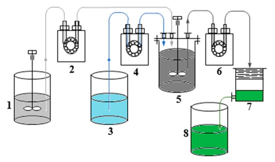
Figure 1.
Experimental set-up for slag leaching in continuous mode. It consisted of (1) a feed tank of pulp, (2), (4), (6) peristaltic pumps, (3) a feed tank of sulfuric acid, (5) a glass reactor, (7) a Nutsche filter and (8) a filtrate tank.
2.4. Recovery of SiO2
The solution was subjected to dehydration to extract silicon dioxide from the sulfuric acid-leaching solution. Dehydration of the solution was performed in a spray dryer (BXT-8000ST, Shanghai Glomro Industrial Co., Ltd., Shanghai, China) at 150 ± 1 °C and 270 ± 1 °C. That solution was dehydrated in parallel in the air at 45 ± 2 °C. The powders were a mixture of SiO2 and metal sulfates (iron, nonferrous metals, magnesium and aluminum). The powders were aqueous washed to separate silicon dioxide from metal sulfates by repulsion at 80 ± 2 °C and S:L = 1:3. The SiO2 samples were dried to a constant weight at 100 ± 2 °C. The sample obtained by dehydration in the air was designated SiO2-40. Samples obtained by dehydration in a spray dryer at temperatures 150 and 270 °C were SiO2-150 and SiO2-270, respectively. Sample SiO2-40 was additionally purified from impurities (SiO2-40C).
2.5. Recovery of Non-Ferrous Metals
The copper cementation from solutions after silicon dioxide separation was carried out as follows: in a glass beaker placed in a thermostat, 1 L of the solution iron powder was added in the ratio Fe: Cu = 5:1 [56,57]. The process was carried out under intensive stirring (1000 rpm) for 0.5 h at 70 ± 1 °C. The solution was filtered, and the cementite was dried at 100 ± 2 °C.
Metal sulfides were precipitated according to the method described by [58]. The difference from the above process was that iron sulfide and magnesium carbonate suspensions were used as precipitants and neutralizing agents, respectively. A 1.0 L solution obtained after copper cementation was added into a reactor with an agitator and pH control. The solution was pre-neutralized with magnesium carbonate emulsion (S:L = 1:10) to pH = 3, to reduce the amount of iron sulfide. Then, to precipitate nickel and cobalt sulfides, iron sulfide suspension (S:L = 1:5) was added to the solution under stirring at a rate such that the pH did not exceed 4.0. The suspension was incubated for 1.0 h at 50 ± 2 °C. After completing precipitation, the suspension was acidified to pH = 1.5 to remove an impurity of co-precipitated iron sulfide from the sulfide concentrate. The sulfide precipitate was filtered, washed with a solution acidified to pH = 3.0, and dried.
2.6. Iron and Magnesium Separation
The solution obtained after the separation of nonferrous metals was subjected to dehydration to separate iron and magnesium. This solution was dehydrated in a spray dryer at 200 ± 1 °C. Sulfate powders were calcined in a Nabertherm RT 50-250/11 tube furnace (Nabertherm GmbH, Lilienthal, Germany) at a temperature of 750, 800 and 850 °C for 3 h. The calcined powders were washed of water-soluble compounds at S:L = 1:5 temperature 80 ± 2 °C for 30 min. As a result, Fe2O3 samples were obtained. The Fe2O3 specimens calcined at 750, 800 and 850 ± 1 °C were designated Fe2O3-750, Fe2O3-800 and Fe2O3-850, respectively.
3. Results and Discussion
3.1. Characterization of Dump Slag
Granulated slag from the Pechenganickel plant consists of dense and tough black granules with a shell-like breakage and a glassy glitter. According to X-ray phase data, magnesia-iron glass (Mg1.04Fe0.96SiO4) is the main mineral component of the presented slag sample (~71%), ferrosilite was found in smaller amounts (FeSiO3) (~29%), as was quartz (SiO2); the sample structure was X-ray amorphous (Figure 2).
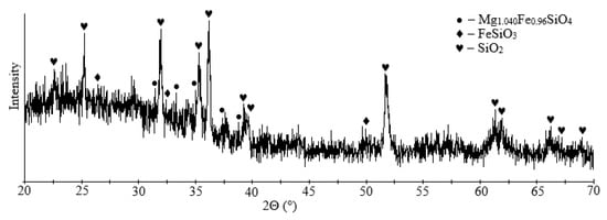
Figure 2.
XRD pattern of initial dump slag.
Mineralogical investigations revealed that the slag matrix consists of olivine, fayalite and glass. Slag glass contains almost no impurities of non-ferrous metals in an isomorphic state; these impurities are concentrated entirely in sulfide alloy inclusions. According to the electron microprobe analysis, the alloy is a pyrrhotite solid solution containing Fe 49–55%, S 34–39%, Ni 4–8%, Cu 2–6% and Co 0.2–0.3%. Inclusions of sulfides in the slag are distributed unevenly and not in all slag grains. Sulfide inclusions are rounded excretions and complex sulfide formations of a curved shape (Figure 3). The sulfide sizes range from 5 to 20 μm. Larger grains up to 50 µm in diameter can also be observed. In the slag matrix, represented by the glass, skeletal needle-like crystals of olivine are observed to form a spinifex structure (Figure 3A,D).
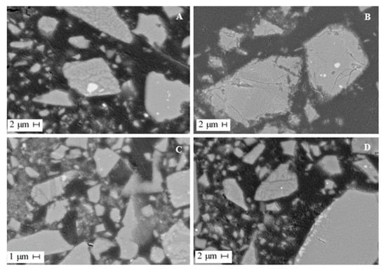
Figure 3.
SEM images of dump slug. (A,B) slag particles with sulfide inclusions of various shapes and sizes, (C,D) slag particles with inclusions of olivine.
3.2. Leaching Slag Test
Based on the mineralogical composition of the slag, the process of decomposition of its target soluble forms by sulfuric acid can be represented by the following chemical reactions:
where Me are Fe, Ni and Co, respectively.
To prevent the release of H2S into the working atmosphere, we proposed a method of slag processing in the presence of copper ions used in a 140–160% excess with the produced hydrogen sulfide [59]. In the presence of copper ions, copper ions interact with the produced hydrogen sulfide to form copper sulfides with a low solubility equilibrium (Ksp) by the following reaction:
At the first stage of work, the periodic study of sulfuric acid leaching behavior of iron, non-ferrous metals, magnesium and silicon depending on the leaching process time, particle size, acid concentration, S:L ratio and temperature was carried out. The results are shown in Figure 4 and Table 1.
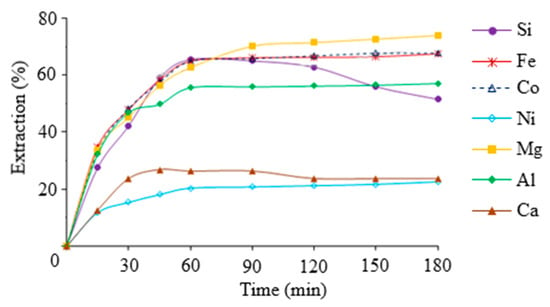
Figure 4.
The extraction percentages of target components from slag as a function of leaching time. Conditions: tinitial = 40 °C, CH2SO4 = 7 wt.%, S:L = 1:9, particle size < 80 μm.

Table 1.
Influence of the main parameters on the extraction of the target slag components in the leaching solution.
As can be seen from the data presented in Figure 2, the recovery of iron, magnesium, nickel, cobalt and aluminum in the leaching solution increases with increasing process duration, and the recovery of silicon and calcium decreases. The decrease in the degree of silicon extraction with increasing process time was caused by partial polycondensation of silicic acid. Reducing the percentage of calcium extraction is associated with a decrease in the solubility of calcium sulfate, and with a rising concentration of other metal sulfates in the leaching solution. Increasing the degree of grinding of the initial slag sample increased the degree of extraction of the target components, while finer grinding (less than 40 μm) significantly reduced the filtration rate. Processing the slag with a sulfuric acid concentration of less than 10% showed that the resulting silica-containing solution was in an aggregation-stable state. Increasing the initial concentration of sulfuric acid leads to a significant increase in leachate viscosity and a risk of premature gelation of the leaching solution. The S:L ratio of less than 6 resulted in insufficient decomposition of the slag and very concentrated silicic acid solutions. It can lead to premature solution coagulation and difficulty separating the solutions from the insoluble residue. The S:L ratio of less than 6 resulted in insufficient decomposition of the slag and very concentrated silicic acid solutions. It leads to excessive consumption of acid and complicates their further processing. Loading the slag into sulfuric acid preheated to 40 °C to improve the performance of the process was found. But further increasing the temperature in the system leads to a decrease in the aggregative stability of the silica-containing solution, and requires increased costs for heating the solution without significantly increasing the degree of dissolution of the silica. As a result, the optimal conditions for slag leaching with sulfuric acid are as follows: CH2SO4 = 7 wt.%, S:L = 1:9, tinitial = 40 ± 2 °C, particle size < 80 μm, τ = 1 h.
Since the slag leaching process in batch mode is less technological on an industrial scale, the tests of slag decomposition with sulfuric acid in the continuous leaching mode were carried out. The data presented in Table 2 were obtained by processing a 5 kg slag sample in continuous mode. Results showed that carrying out the process in continuous operation makes it possible to achieve similar results obtained in batch mode. In this case, the process productivity increases by reducing the time spent on stops for loading and unloading slag.
Table 2.
Valuable component distribution in slag leaching with sulfuric acid solution in continuous mode. Conditions: CH2SO4 = 7 wt.%, S:L = 1:9, tinitial = 40 ± 2 °C, particle size < 80 μm.
To increase the degree of extraction of silicon and iron from the slag, we examined the possibility of a two-stage slag treatment. The second leaching stage was also carried out in the reactor in a continuous mode at S:L = 1:5. The results are presented in Table 3.
Table 3.
Valuable component distribution in slag leaching with sulfuric acid solution in continuous mode (stage 2 of slag leaching). Conditions: CH2SO4 = 7 wt.%, S:L = 1:5, tinitial = 40 ± 2 °C.
As a result of a two-stage slag processing with sulfuric acid, the extractions of components were, in wt.%: 72.7 Si, 77.7 Fe, 73.3 Co, 34.5 Ni, 17 Cu, 78.8 Mg, 69.3 Al and 55.0 Ca. The decrease in slag mass after the first leaching stage was 2.5 times, and after the second stage was 1.5 times; the total slag reduction was 3.7 times.
X-ray phase analysis indicates that ferrosilite (2(Mg0.56Fe0.44)O·SiO2)) and calcium sulfate (Ca(SO4)(H2O)2) form the basis of the cakes after first stage sulfuric acid leaching of slag (Figure 5). After the second leaching stage, the residue was magnesium silicate (Mg2SiO4) and quartz (SiO2).
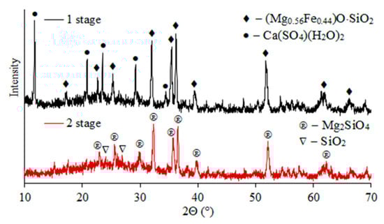
Figure 5.
X-ray diffraction patterns of residues after stages 1 and 2 of sulfuric acid leaching of slag.
The mineralogical analysis of residues after the first and second stages of sulfuric acid leaching was carried out (Figure 6). The dissolution of the amorphous component of the slag was found to release sulfide inclusions. According to microprobe analysis after the first leaching step, sulfide particles contain, wt.%: 24.0–35.0 Fe, 3.0–10.0 Cu, 8.0–17.0 Ni, 0.6–1.7 Co and 18.0–36.0 S; after the second, wt.%: 25.0–29.0 Fe, 2.0–6.0 Cu, 7.0–22.0 Ni, 0.6–1.7 Co and 17.0–39.0 S.
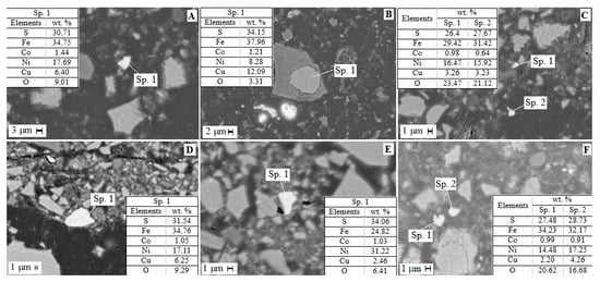
Figure 6.
SEM images of residue after sulfuric acid leaching of slag: (A–C) stage 1, (D–F) stage 2.
Thus, two-stage leaching resulted in the disclosure of sulfide particles encapsulated in ferrosilite. This fact is favorable for the use of, for example, flotation to obtain a concentrate of non-ferrous metals [18,60]. The residue after non-ferrous metal extraction can effectively be used in the construction industry [27,28,29].
3.3. SiO2 Recovery from Sulfuric Acid Slag Leaching Solutions
In sulfuric acid technology of slag processing, filtrate stability is essential. As a result of the polymerization of silicic acid in these solutions over time, structural formation processes occur, which leads to gelation in the system. Without external influences, gel formation in the solution after leaching can occur during the first hours and within the next three to four days. The first stage of polymerization is the formation of a polysilicon acid sol, followed by particle structure formation with the appearance of a gel. One of the most significant rheological parameters characterizing the transition of a sol into a gel is viscosity, the growth of which precedes the formation of a gel. In this regard, the viscosity of the filtrate obtained in Section 3.2 was studied at the first stage of the study of filtrate processing options. The silica content in the solution was 12.5 g·L−1. The filtrates were kept at room temperature (20 ± 2 °C) for 8–9 days until gelation. The results are shown in Table 4.
Table 4.
Dependence of solution viscosity on leaching solution residence time.
As can be seen from the presented data, the solution viscosity changes over time, and three sections can be distinguished. The first section of a slight increase in viscosity corresponds to the induction period (up to 4–5 days). The second period is characterized by an intense viscosity increase (more than 4–5 days). The third period is characterized by viscosity fluctuations (the measurement error is more than 20%). A viscosity value of 2.4 mPa·c can be considered the beginning of gelation. Thus, it was established that the solutions obtained by sulfuric acid leaching of slag are stored without gelatinization for 4–5 days. Thus, the relatively high stability of solutions allows one to carry out all technological operations without the risk of gelatinization of solutions.
Silicon dioxide obtained from solutions resulting from sulfuric acid leaching of slag was considered. Solution composition was, in g·L−1: 18.9 Fe, 12.5 Si, 0.4 Cu, 0.05 Ni, 0.07 Co, 5.6 Mg, 1.98 Al and 0.5 Ca. Depending on the dehydration temperature, silicon dioxide with different textural characteristics was found to occur. The morphology of silica particles obtained at different dehydration temperatures is shown in Figure 7. As can be seen, the shape and size of the SiO2 particles change with increasing dehydration temperature. At a dehydration temperature of 40 °C (sample SiO2-40), particles of 5–10 μm and large irregularly shaped particles larger than 120 μm are formed. As the dehydration temperature increases, the sample becomes more homogeneous, the particles decrease to 1–7 μm, and a small number of large irregularly shaped fused particles are detected. Treatment of the SiO2-40 sample with hydrochloric acid does not change the shape and size of the particles.
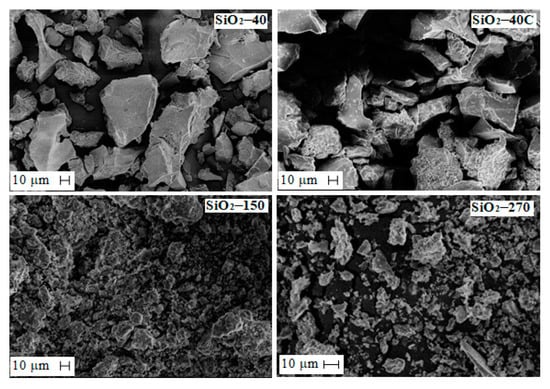
Figure 7.
SEM micrographs of SiO2 particles obtained at different conditions.
Figure 8 shows the adsorption–desorption isotherms of N2 for the SiO2 samples. Nitrogen adsorption isotherms for all specimens belong to type IV, and are characterized by a hysteresis loop in the region (P/P0) from 0.4 to 1.0. As seen from the data presented in Figure 8, the isotherm for the SiO2-40C specimen has an initial section with a less sharp increase at P/P0 < 0.1. This fact indicates that there are practically no micropores in this sample. For the other materials, the sharp increases at P/P0 < 0.1 and the narrow H4-type hysteresis loop at higher pressures indicate a combination of micro- and mesopores [38,61,62,63,64].
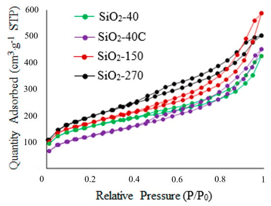
Figure 8.
Nitrogen adsorption/desorption isotherms for SiO2 specimens.
The textural characteristics of SiO2 specimens are shown in Table 5. As can be seen, with increasing dehydration temperature, the sample-specific surface area grows with overall pore volume rises, and the micropore fraction decreases from 9.1 to 3.6%. The micropore fraction is less than 1.5% when the SiO2-40 sample is washed with hydrochloric acid.
Table 5.
The textural characteristics of SiO2 specimens.
Studies of the particle size distribution of SiO2 samples exposed to ultrasonic dispersion showed that the average particle size decreases with an increase in the specific surface area of the specimens; the smallest particle size has the sample SiO2-270 (Figure 9). According to the results, the SiO2-40 sample, with a surface area of 525 m2·g−1, has a particle size of less than 2 to 120 μm, with 75% being less than 60 μm, 50% less than 36 μm and 15% less than 8 μm (Figure 9A). When the SiO2-40 sample is treated with hydrochloric acid, the particle distribution does not change (data for the SiO2-40C specimen were not presented). For the SiO2-150, the particle size varies from 1.2 to 82 μm, with 95% being smaller than 53 μm, 75% smaller than 22 μm, and 41.6% smaller than 8.1 μm (Figure 9B). For sample SiO2-270, the particle size varies from 1.6 to 49.8 μm, with 49% being less than 7 μm (Figure 9C). The decrease in the average particle size is probably due to the faster kinetics of SiO2 particle formation with an increasing dehydration temperature.
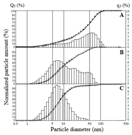
Figure 9.
Particle size distribution for SiO2 samples: (A) SiO2-40, (B) SiO2-150, (C) SiO2-270.
The chemical composition and the main characteristics of SiO2 samples are presented in Table 6. The results presented in the table show that the efficiency of washing metals from SiO2 samples increases with increasing dehydration temperature. SiO2-40 specimen was processed with solutions of oxalic ( = 5–10%) and hydrochloric (CHCl = 5–28%) acids at S:L = 1:5, τ = 15 min, t = 80 ± 2 °C (data not shown here). Processing with 5–10% hydrochloric acid solutions proved to be the most effective, as a result of which the total impurity content in the sample does not exceed 0.20% (sample SiO2-40C).
Table 6.
The chemical compositions and the main characteristics of SiO2 samples.
Thus, as a result of the work found, it was shown that in the sulfuric acid treatment of slag, silica with different qualitative characteristics can be obtained. The dependence of the morphology and surface characteristics of the samples on the dehydration temperature was established. Obtained silica can be used as a thickener, anti-caking agent, carrier for catalysts, and also for obtaining sorbents [64].
3.4. Solution Processing after SiO2 Extraction
Washing of the dehydrated powder and separation of silica resulted in concentrated solutions of iron, nonferrous metals and magnesium sulfate, with the following composition, g·L−1: 34.0 Fe, 0.82 Cu, 0.099 Ni, 0.13 Co, 10.5 Mg, 0.45 Ca and 3.6 Al. Separation of iron, magnesium, aluminum and nonferrous metals from this solution into separate products was considered. Several existing methods for processing such solutions may include cementation, sulfide or hydroxide precipitation, crystallization and extraction. The arguments for preferential use of cementation and metal sulfide are based on the high degree of metal removal at relatively low pH values, the sparingly soluble nature of sulfide precipitates, favorable dewatering characteristics, and the stability of the metal sulfides formed [57,65].
3.4.1. Non-Ferrous Metals Recovery
The traditional option for removing copper from acidic effluent, mine and quarry waters is cementation with metallic iron, which can result in copper concentrate [57]. As a result of cementation, a copper recovery of more than 99% was achieved, and the residual copper content in the solution was 0.5 ppm. According to XRD data, copper cementite contains copper and copper oxide (Figure 10). The blister copper obtained can be used for smelting in production.
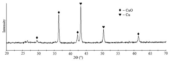
Figure 10.
XRD pattern of cementite.
Next, according to the method described in Section 2.5, the solution was purified from nickel and cobalt. The resulting sulfide residue was obtained with the following composition, in wt.%: 94.58 S, 4.16 Fe, 0.37 Si, 0.28 Co, 0.13 Ni, 0.06 Cu and 0.05 Ca. The nickel and cobalt recovery were over 96%. The nickel and cobalt remaining content were, in ppm: 0.15 Co, 0.63 Ni. According to the X-ray phase analysis, the residue was present by elemental sulfur, nickel and cobalt sulfides, and magnetite (Figure 11). This residue can be successfully combined with the flotation concentrate from Section 3.2.
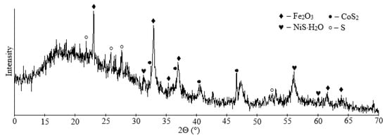
Figure 11.
XRD pattern of sulfide residue.
3.4.2. Production of Iron Oxide Powders and Magnesium Sulfate
Iron and magnesium can be separated by hydrolytic precipitation of iron, recrystallization or by electroflotation methods [66,67]. Generally, these methods are based on the pre-oxidation of iron(II) to iron(III). However, these methods are not devoid of disadvantages, since hydrolytic precipitation produces contaminated, hard-to-filter high-watered residues. Crystallization often does not achieve 100% yield of the target component. The need to dilute concentrated solutions is a significant disadvantage when using electroflotation. For separating iron and magnesium from solutions after nonferrous metal extraction, we proposed a principally new approach based on temperature differences in the thermal decomposition of sulfates that are part of the obtained solutions. It is well known that an iron (II) and aluminum sulfate thermal decomposition reaction with the formation of their oxides occurs in the temperature range of 580–750 °C, and the decomposition of magnesium sulfate to form magnesium oxide occurs at temperatures above 1100 °C. The solution obtained after extraction of the nonferrous metals was dehydrated in a spray dryer at 200 °C. The result was a powder containing iron, aluminum, magnesium and calcium sulfates. Figure 12 lists the results of the TG-DTA analysis of the dehydrated powder. According to the thermogravimetric analysis, the thermogram of the sample includes several stages of mass loss. The first stage of heating from room temperature to 250 °C involved the removal of physically adsorbed water. Accordingly, peaks corresponding to the endothermic effect are observed in the specified temperature range. Weight loss at this stage is 21.59%. In the second stage, the mass loss is 40.34%. The DTA curve of the samples exhibits two peaks at 720 and 740 °C. In this temperature range, iron and aluminum sulfates decompose to their oxides.
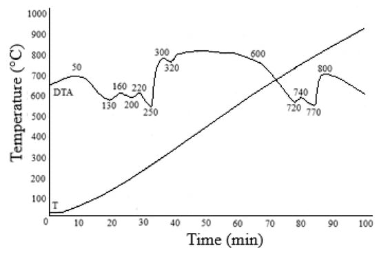
Figure 12.
Results of the TG/DTA of the FeMgSO4 mixture dehydrated at 200 °C.
Table 7 presents the results of aqueous leaching of sulphate powders calcined at different temperatures. The data presented in Table 6 show that the degree of transformation of metal sulfates into their oxides increases with increasing calcination temperature, and the transition of impurity elements (Mg, Ca and Al) into iron oxide powder increases.
Table 7.
Solution composition and extraction of target components in aqueous leaching solution of calcined sulfate powders.
It has been found that, with additional washing of iron oxide powders with 2 M H2SO4, it is possible to improve the quality of iron oxide powders (Table 8). Aluminum (up to 3.4 wt.% Al2O3) remains the main impurity entering the samples. After calcium removal by recrystallization [68] of the magnesium sulfate solution, with subsequent evaporation of the solution, magnesium sulfate containing 0.005 wt.% CaO was obtained (Table 8).
Table 8.
The qualitative indicators of iron oxide powders.
From particle size distribution analysis of the Fe2O3-750 specimen, shown in Figure 13, it was found that 7.2% of the particles have an average volume equivalent spherical diameter of less than 3.28 μm, 24.8% have 20.3 μm, and 98% have less than 3.4 μm. Sample particle sizes of Fe2O3-800 and Fe2O3-850 vary from 0.289 to 5.24 μm, and with increasing calcination temperature, the fraction of particles larger than 1.065 μm rises negligibly. So, in the interval 1.065–5.24 μm, the particle fraction for the sample Fe2O3-800 is 73.45%, for the sample Fe2O3-850 is 79.5%, also in the sample Fe2O3-850, and the fraction of particles with sizes less than 1.065 μm is reduced by 5%. Thus, as the calcination temperature increases, there is a slight decrease in dispersity associated with particle sintering. It should be noted that the obtained samples are characterized by a lower interval of particle size distribution, as compared to the standard specimen (Fe2O3 R130), where the particle distribution varies in the range of 0.596–25.791 μm.
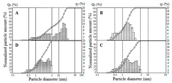
Figure 13.
Particle-size distribution for Fe2O3 samples: (A) Fe2O3 R130, (B) Fe2O3-750, (C) Fe2O3-800, (D) Fe2O3-850.
The colorimetric parameters of the Fe2O3 samples, obtained at different calcination temperatures, and a commercial specimen of iron oxide pigment R130, were measured (Figure 14, Table 9). As can be seen from the data presented in Table 8, the samples become reddish as the calcination temperature increases. Thus, if there is a significant contribution of green and yellow color at the temperature of calcination at 750 °C, the reddish coloration increases with increasing temperature of calcination. The sample calcined at 850 °C shows the best tonal results compared to the Fe2O3-750 and Fe2O3-800 samples, with a high red color contribution and a lower contribution of yellow. The higher blue color contribution in the sample Fe2O3-850 compared with the sample Fe2O3-R130 is probably due to impurity in the form of aluminum oxide and a smaller particle size. The color difference was 2.1%.
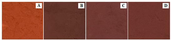
Figure 14.
Influence of calcination temperature of (FeMg)SO4 mixture on the color of iron oxide powders: (A) Fe2O3-750, (B) Fe2O3-800, (C) Fe2O3-850, (D) Fe2O3 R130.
Table 9.
Colorimetric analysis.
The resulting iron oxide powders can be successfully used with a high degree of probability as, for example, color and anticorrosive pigments [69,70,71,72], since the powders are characterized by homogeneous particle size in a relatively narrow range, the pH of the water extract is in the interval of 4.0–4.6, and the content of the water-soluble substance is less than 1.0 wt.% (Table 7).
3.5. Scheme of Sulfuric Acid Processing of Dump Slag
According to the obtained results, a slag utilization scheme was proposed, which includes slag leaching with a sulfuric acid solution, dehydration of leaching solutions, and washing of dehydrated powder to obtain amorphous silica and a solution containing iron, magnesium, aluminum and non-ferrous metal sulfates (Figure 15). The residue is a flotation to produce a concentrate of non-ferrous metals. The residual can be used in the construction industry. Cementation separates copper, nickel and cobalt from the solution obtained, and precipitates as sulfides. The solution obtained after the separation of non-ferrous metals is subjected to dehydration, followed by washing from water-soluble impurities and received iron oxide powder and the solution containing magnesium and calcium sulfates. Then, the filtrate is recrystallized to separate calcium sulfate. After the crystallization of the solution purified of calcium ions, magnesium sulfate is obtained.
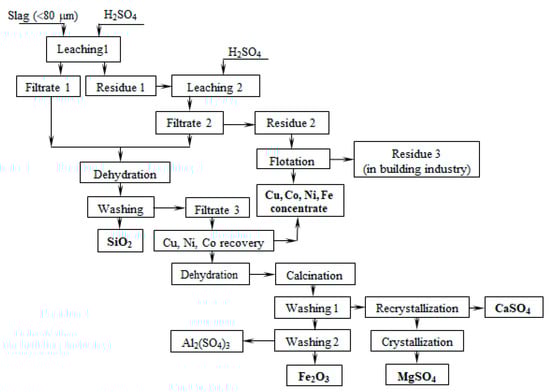
Figure 15.
Principle scheme of Cu-Ni dumped slug utilization.
4. Conclusions
- (1)
- A new method of utilizing waste slag from copper-nickel production was developed. The method includes two-stage slag decomposition with dilute solutions of sulfuric acid (7–10 wt.%) with more than 70% silicon, 77% iron and 78% magnesium in the solution, and a concentration of base metals in the residue, separation of silicon dioxide from leaching solutions by solution dehydration, separation of iron oxide powder and magnesium sulfate by solution dehydration, and subsequent calcination of dehydrated powder;
- (2)
- The effect of leaching solution dehydration temperature on the morphology and surface characteristics of silica was shown. Silica particle size decreased from 60 to 7 μm when the dehydration temperature was increased from 40 to 270 °C;
- (3)
- A method of separating iron and magnesium from solutions was developed. The difference in decomposition temperatures of iron and magnesium sulphates was based on the process. The calcination of dehydrated powder at 750–850 °C, followed by water leaching, allows the obtaining of iron dioxide of pigment quality and magnesium sulphate;
- (4)
- Due to sulfuric acid leaching in the undecomposed residue, sulfide grains encapsulated in ferrosilicate were exposed, which is a favorable factor for flotation. The depleted residue can be successfully used in the construction industry.
5. Patents
Kasikov, A.G.; Shchelokova, E.A.; Timoshchik, O.A.; Budnikova, N.N. Method for processing metallurgical slag Patent 2765974 RU, 7 February 2022.
Author Contributions
Conceptualization, A.G.K. and E.A.S.; methodology, A.G.K. and E.A.S.; software, A.G.K. and E.A.S.; validation, A.G.K. and E.A.S.; formal analysis, A.G.K. and E.A.S.; investigation, A.G.K., E.A.S., O.A.T. and V.V.S.; resources, A.G.K. and E.A.S.; data curation, A.G.K., E.A.S., O.A.T. and V.V.S.; writing—original draft preparation, E.A.S.; writing—review and editing, A.G.K.; visualization, A.G.K., E.A.S., O.A.T. and V.V.S.; supervision, A.G.K. and E.A.S. All authors have read and agreed to the published version of the manuscript.
Funding
This study is supported by the Ministry of Science and Higher Education Russian Federation scientific topic No FMEZ-2022-0018.
Data Availability Statement
All data are available in this study.
Acknowledgments
The authors grateful to the joint-stock company trading house “GALION”, Russia, represented by V.V. Strogonov for the financial support and approval of this work for publication.
Conflicts of Interest
The authors declare no conflict of interest.
References
- Nornickel. Expanding the Horizons of Sustainable Growth. Annual Report. 2019. Available online: https://ar2019.nornickel.com/strategic-report/key-investment-projects/environmental (accessed on 15 May 2023).
- Zosin, A.P.; Priymak, T.I.; Koshkina, L.B. Ecological aspects of geochemical transformation processes of mineral waste from the processing of sulfide copper-nickel ores. Ekol. Khimiya 2003, 12, 34–42. [Google Scholar]
- Parshina, M.V. Ecological and geochemical peculiarities of transformation of slag dumps in the acidification zone. J. Min. Inst. 2006, 167, 90–93. [Google Scholar]
- Moncur, M.C.; Jambor, J.L.; Ptacek, C.J.; Blowes, D.W. Mine drainage from the weathering of sulfide minerals and magnetite. Appl. Geochem. 2009, 24, 2362–2373. [Google Scholar] [CrossRef]
- Potapov, D.S.; Svetlov, A.V.; Potapov, S.S.; Men’shikov, Y.P.; Nesterov, D.P.; Makarov, D.V. Experimental modeling of weathering uneven slag copper-nickel production. Mineral. Tekhnogenezisa 2013, 14, 38–49. [Google Scholar]
- Moncur, M.C.; Ptacek, C.J.; Hayashi, M.; Blowes, D.W.; Birks, S.J. Seasonal cycling and mass-loading of dissolved metals and sulfate discharging from an abandoned mine site in northern Canada. Appl. Geochem. 2013, 41, 176–188. [Google Scholar] [CrossRef]
- Kasikov, A.; Neradovsky, Y.; Huber, M.; Mayorova, Y.; Rakitina, E.; Grishin, N. Heterogeneity of glass components in slagafter nickel acquisition process from Kola Peninsula (Russia). Metall. Foundry Eng. 2017, 43, 89–96. [Google Scholar] [CrossRef]
- Ettler, V.; Mihaljevič, M.; Drahota, P.; Kříbek, B.; Nyambe, I.; Vaněk, A.; Penížek, V.; Sracek, O.; Natherová, V. Cobalt-bearing copper slags from Luanshya (Zambian Copperbelt): Mineralogy, geochemistry, and potential recovery of critical metals. J. Geochem. Explor. 2022, 237, 106987. [Google Scholar] [CrossRef]
- Zhang, H.-B.; Wang, Y.-N.; Zhu, Y.-B.; Ren, P.; Hu, B.; Xu, S.-H.; Cao, H.-Z.; Zhou, J.; Zheng, G.-Q. Determination of occurrence and leaching toxicity of arsenic in copper flash smelting slags. Trans. Nonferrous Met. Soc. China 2023, 33, 293–303. [Google Scholar] [CrossRef]
- Nicholson, R.V.; Scharer, J.M. Laboratory Studies of Pyrrhotite Oxidation Kinetics. Environ. Geochem. Sulfide Oxid. 1993, 2, 14–30. [Google Scholar]
- Heikkinen, P.M.; Räisänen, M.L.; Johnson, R.H. Geochemical characterization of seepage and drainage water quality from two sulphide mine tailings impoundments: Acid mine drainage versus neutral mine drainage. Mine Water Environ. 2009, 28, 30–49. [Google Scholar] [CrossRef]
- Dold, B. Basic concepts in environmental geochemistry of sulphide minewaste management. In Waste Management; Kumar, S., Ed.; InTech: Rijeka, Croatia, 2010; pp. 173–198. [Google Scholar]
- Warren, L.A. Acid Rock Drainage. In Encyclopedia of Geobiology. Encyclopedia of Earth Sciences Series; Reitner, J., Thiel, V., Eds.; Springer: Dordrecht, The Netherlands, 2011; pp. 5–8. [Google Scholar]
- Marescotti, P.; Carbone, C.; Comodi, P.; Frondini, F.; Lucchetti, G. Mineralogical and chemical evolution of ochreous precipitates from the Libiola Fe-Cu-sulfide mine (Eastern Liguria, Italy). Appl. Geochem. 2012, 27, 577–589. [Google Scholar] [CrossRef]
- Valente, T.; Grande, J.A.; de la Torre, M.L.; Santisteban, M.; Cerón, J.C. Mineralogy and environmental relevance of AMD-precipitates from the Tharsis mines, Iberian Pyrite Belt (SW, Spain). Appl. Geochem. 2013, 39, 11–25. [Google Scholar] [CrossRef]
- Jiao, Y.; Zhang, C.; Su, P.; Tang, Y.; Huang, Z.; Ma, T. A review of acid mine drainage: Formation mechanism, treatment technology, typical engineering cases and resource utilization. Process Saf. Environ. Prot. 2023, 170, 1240–1260. [Google Scholar] [CrossRef]
- Alp, I.; Deveci, H.; Süngün, H. Utilisation of flotation wastes of copper slag as raw material in cement production. J. Haz. Mater. 2008, 159, 390–395. [Google Scholar] [CrossRef]
- Piatak, N.M.; Parsons, M.B.; Seal, R.R., II. Characteristics and environmental aspects of slag: A review. Appl. Geochem. 2015, 57, 236–266. [Google Scholar] [CrossRef]
- Liao, M.-I.; Shih, X.-H.; Ma, H.-W. Secondary copper resource recycling and reuse: A waste input–output model. J. Clean. Prod. 2019, 239, 118142. [Google Scholar] [CrossRef]
- Gümüşsoy, A.; Başyiğit, M.; Kart, E.U. Economic potential and environmental impact of metal recovery from copper slag flotation tailings. Resour. Policy 2023, 80, 103232. [Google Scholar] [CrossRef]
- EIT. EIT RawMaterials Call for KAVA Projects SeedBook User Guide; EIT: Stockholm, Sweden, 2020; pp. 1–2. [Google Scholar]
- Shen, H.; Forssberg, E. An overview of recovery of metals from slags. Waste Manag. 2003, 23, 933–949. [Google Scholar] [CrossRef]
- Phiri, T.C.; Singh, P.; Nikoloski, A.N. The potential for copper slag waste as a resource for a circular economy: A review—Part II. Miner. Eng. 2021, 172, 107150. [Google Scholar] [CrossRef]
- Yang, J.; Firsbach, F.; Sohn, I. Pyrometallurgical processing of ferrous slag “co-product” zero waste full utilization: A critical review. Resour. Conserv. Recycl. 2022, 178, 106021. [Google Scholar] [CrossRef]
- Phiri, T.C.; Singh, P.; Nikoloski, A.N. The potential for copper slag waste as a resource for a circular economy: A review—Part I. Miner. Eng. 2022, 180, 107474. [Google Scholar] [CrossRef]
- Al-Jabri, K.S.; Al-Saidy, A.H.; Taha, R. Effect of copper slag as a fine aggregate on the properties of cement mortars and concrete. Constr. Build. Mater. 2011, 25, 933–938. [Google Scholar] [CrossRef]
- Nath, S.K.; Randhawa, N.S.; Kumar, S. A review on characteristics of silico-manganese slag and its utilization into construction materials. Resour. Conserv. Recycl. 2022, 176, 105946. [Google Scholar] [CrossRef]
- Soni, J.; Chokshi, T.; Sharma, R.; Gujar, R.; Jariwala, N. Assessing the Applicability of Fine Copper Slag in Road and Structural Fill Application. Mater. Today Proc. 2022, 62, 7040–7043. [Google Scholar] [CrossRef]
- Adediran, A.; Yliniemi, J.; Lemougna, P.N.; Perumal, P.; Illikainen, M. Recycling high volume Fe-rich fayalite slag in blended alkali-activated materials: Effect of ladle and blast furnace slags on the fresh and hardened state properties. J. Build. Eng. 2023, 63, 105436. [Google Scholar] [CrossRef]
- Kumar, P.; Shukla, S. Utilization of steel slag waste as construction material: A review. Mater. Today Proc. 2023, 78, 145–152. [Google Scholar] [CrossRef]
- Çoruh, S.; Ergun, O.N.; Cheng, T.-W. Treatment of copper industry waste and production of sintered glass-ceramic. Waste Manag. Res. 2006, 24, 234–241. [Google Scholar] [CrossRef]
- Zhai, X.-J.; Li, N.-J.; Zhang, X.; Fu, Y.; Jiang, L. Recovery of cobalt from converter slag of Chambishi Copper Smelter using reduction smelting process. Trans. Nonferrous Met. Soc. China 2011, 21, 2117–2121. [Google Scholar] [CrossRef]
- Tyszka, R.; Kleczka, J.; Pietranik, A.; Ettler, V.; Mihaljevič, M. Extensive weathering of zinc smelting slag in a heap in Upper Silesia (Poland): Potential environmental risks posed by mechanical disturbance of slag deposits. Appl. Geochem. 2014, 40, 70–81. [Google Scholar] [CrossRef]
- Singh, S.K.; Vashistha, P.; Chandra, R.; Rai, A.K. Study on leaching of electric arc furnace (EAF) slag for its sustainable applications as construction material. Process Saf. Environ. Prot. 2021, 148, 1315–1326. [Google Scholar] [CrossRef]
- Mikula, K.; Skrzypczak, D.; Izydorczyk, G.; Baśladyńska, S.; Szustakiewicz, K.; Gorazda, K.; Moustakas, K.; Chojnacka, K.; Witek-Krowiak, A. From hazardous waste to fertilizer: Recovery of high-value metals from smelter slags. Chemosphere 2022, 297, 134226. [Google Scholar] [CrossRef]
- Zuo, Z.; Feng, Y.; Dong, X.; Luo, S.; Ren, D.; Wang, W.; Wu, Y.; Yu, Q.; Lin, H.; Lin, X. Advances in recovery of valuable metals and waste heat from copper slag. Fuel Process. Technol. 2022, 235, 107361. [Google Scholar] [CrossRef]
- Almada, B.S.; da Silva Neto, G.A.; do Prado, D.F.; Aguilar, M.T.P.; Garcia, D.C.S.; Silva, G.J.B.; dos Santos, W.J. Evaluation of the microstructure and micromechanics properties of structural mortars with addition of iron ore tailings. J. Build. Eng. 2023, 63, 105405. [Google Scholar] [CrossRef]
- Yang, C.-M.; Zibrowius, B.; Schmidt, W.; Schüth, F. Consecutive Generation of Mesopores and Micropores in SBA-15. Chem. Mater. 2003, 15, 3739–3741. [Google Scholar] [CrossRef]
- Pan, J.; Zheng, G.-L.; Zhu, D.-Q.; Zhou, X.-L. Utilization of nickel slag using selective reduction followed by magnetic separation. Trans. Nonferrous Met. Soc. China 2013, 23, 3421–3427. [Google Scholar] [CrossRef]
- Turan, M.D.; Sari, Z.A.; Miller, J.D. Leaching of blended copper slag in microwave oven. Trans. Nonferrous Met. Soc. China 2017, 27, 1404–1410. [Google Scholar] [CrossRef]
- Wang, H.-J.; Liu, Z.-Y.; Li, Y.-H.; Li, S.-W.; Zhang, W.-H.; Li, Q.-H. Leaching of iron concentrate separated from kiln slag in zinc hydrometallurgy with hydrochloric acid and its mechanism. Trans. Nonferrous Met. Soc. China 2017, 27, 901–907. [Google Scholar] [CrossRef]
- Li, X.-M.; Wen, Z.-Y.; Li, Y.; Yang, H.-B.; Xing, X.-D. Improvement of carbothermic reduction of nickel slag by addition of CaCO3. Trans. Nonferrous Met. Soc. China 2019, 29, 2658–2666. [Google Scholar] [CrossRef]
- Zhang, B.-K.; Guo, X.-Y.; Wang, Q.-M.; Tian, Q.-H. Thermodynamic analysis and process optimization of zinc and lead recovery from copper smelting slag with chlorination roasting. Trans. Nonferrous Met. Soc. China 2021, 31, 3905–3917. [Google Scholar] [CrossRef]
- Tian, H.; Guo, Z.; Pan, J.; Zhu, D.; Yang, C.; Xue, Y.; Li, S.; Wang, D. Comprehensive review on metallurgical recycling and cleaning of copper slag. Resour. Conserv. Recycl. 2021, 168, 105366. [Google Scholar] [CrossRef]
- Du, J.; Zhang, F.; Hu, J.; Yang, S.; Liu, H.; Wang, H. Direct reduction of copper slag using rubber seed oil as a reductant: Iron recycling and thermokinetics. J. Clean. Prod. 2022, 363, 132546. [Google Scholar] [CrossRef]
- Wang, Q.; Ma, H.; Liu, M.; Guo, R.; Liu, G. A new method of full resource utilization of copper slag. Hydrometallurgy 2022, 212, 105899. [Google Scholar] [CrossRef]
- Zhou, W.; Liu, X.; Lyu, X.; Gao, W.; Su, H.; Li, C. Extraction and separation of copper and iron from copper smelting slag: A review. J. Clean. Prod. 2022, 368, 133095. [Google Scholar] [CrossRef]
- Xie, S.; Yuan, X.; Liu, F.; Zhao, B. Control of Copper Content in Flash Smelting Slag and the Recovery of Valuable Metals from Slag—A Thermodynamic Consideration. Metals 2023, 13, 153. [Google Scholar] [CrossRef]
- Zhao, B.; Kong, X.; Sun, Y.; Han, Y.; Li, Y. Novel metallic Fe recovery from copper smelting slag by the deep reduction method with renewable biochar reducing agent: Phase transformation process and Fe particle growth optimization. Process Saf. Environ. Prot. 2023, 175, 303–318. [Google Scholar] [CrossRef]
- Kasikov, A.G.; Shchelokova, E.A.; Timoshchik, O.A.; Sokolov, A.Y. Utilization of Converter Slag from Nickel Production by Hydrometallurgical Method. Metals 2022, 12, 1934. [Google Scholar] [CrossRef]
- Kasikov, A.G.; Shelokova, E.A.; Sokolov, A.Y.; Mayorova, E.A. Processing and recycling of iron-bearing copper–nickel production waste. Gornyi Zhurnal 2020, 9, 91–95. [Google Scholar] [CrossRef]
- Della, V.P.; Junkes, J.A.; Montedo, O.R.K.; Oliveira, A.P.N.; Rambo, C.R.; Hotza, D. Synthesis of Hematite from Steel Scrap to Produce Ceramic Pigments. Am. Ceram. Soc. Bull. 2007, 86, 9101–9105. [Google Scholar]
- Commission International de l’Éclairage. CIE 15:2018: Colorimetry, 4th ed.; CIE Central Bureau: Vienna, Austria, 2018; ISBN 978-3-902842-13-8. [Google Scholar]
- Colpas-Ruiz, M.A.; Gnecco-Molina, C.; Pérez-Mendoza, J.; Higuera-Cobos, O.; Jiménez-Rodríguez, G. Obtaining a hematite pigment by thermal transformation of the surface oxide of reinforcing steel bars. Rev. UIS Ing. 2020, 19, 143–152. [Google Scholar] [CrossRef]
- Aziz, N.F.A.A.; Shariff, A.M.; Shaikh, M.S.; Keong, L.K.; Garg, S.; Aftab, A. Physical Properties of Aqueous Sodium Salt Solution of α-Methylalanine (Na-AMALA). 4th International Conference on Process Engineering and Advanced Materials. Procedia Eng. 2016, 148, 444–450. [Google Scholar] [CrossRef]
- Stefanowicz, T.; Osińska, M.; Napieralska-Zagozda, S. Copper recovery by the cementation method. Hydrometallurgy 1997, 47, 69–90. [Google Scholar] [CrossRef]
- Klyushnikov, A.M. Removal of Copper from Underspoil Water of Mines by Cementation. J. Min. Sci. 2020, 56, 142–148. [Google Scholar] [CrossRef]
- Orlov, S.L.; Baskov, D.B. Method of Sedimentation of Nickel and Cobalt Sulfide Concentrate from Sulfuric Acid Solutions. Patent 2281978 RU, 20 August 2006. [Google Scholar]
- Kasikov, A.G.; Shchelokova, E.A.; Timoshchik, O.A.; Budnikova, N.N. Method for Processing Metallugical Slag. Patent 2765974 RU, 7 February 2022. [Google Scholar]
- Zhou, H.; Liu, G.; Zhang, L.; Zhou, C. Mineralogical and morphological factors affecting the separation of copper and arsenic in flash copper smelting slag flotation beneficiation process. J. Haz. Mater. 2021, 401, 123293. [Google Scholar] [CrossRef]
- Galarneau, A.; Cambon, H.; Renzo, F.D.; Fajula, F. True microporosity and surface area of mesoporous SBA-15 silicas as a function of synthesis temperature. Langmuir 2001, 17, 8328–8335. [Google Scholar] [CrossRef]
- Sonwane, C.G.; Ludovice, P.J. A note on micro- and mesopores in the walls of SBA-15 and hysteresis of adsorption isotherms. J. Mol. Catal. A Chem. 2005, 238, 135–137. [Google Scholar] [CrossRef]
- Thielemann, J.P.; Girgsdies, F.; Schlögl, R.; Hess, C. Pore structure and surfaxe ares of Solica SBA-15: Influence of washing and scale-up. Beilstein J. Nanotechnol. 2011, 2, 110–118. [Google Scholar] [CrossRef] [PubMed]
- Alothman, Z.A. A review: Fundamental aspects of silicate mesoporous materials. Materials 2012, 5, 2874–2902. [Google Scholar] [CrossRef]
- Lewis, A.; Hille, R. An exploration into the sulphide precipitation method and its effect on metal sulphide removal. Hydrometallurgy 2006, 81, 197–204. [Google Scholar] [CrossRef]
- Dobrovolskij, I.P.; Kapkaev, Y.S.; Barkhatov, V.I.; Kostyunin, S.V.; Kostyunina, I.L.; Abyzov, V.A. Method for Producing Magnesium Sulphate and Iron-Oxides Pigments from Production. Wastes. Patent 2634017 RU, 23 October 2017. [Google Scholar]
- Inshakova, K.A.; Kharitona, Y.V.; Brodskiy, V.A.; Malkova, Y.O. Extraction low-solubility iron(III) compounds from a high concentrated magnesium sulphate solution by electroflotation. Uspekhi V Khimii I Khimicheskoy Tekhnologii 2019, 33, 66–67. [Google Scholar]
- Gil’fanova, E.A.; Mamontova, A.P.; Murav’ev, A.A.; Mustakimova, M.A.; Pankov, V.P. Method for Purification of Magnesium Sulfate Solutions from. Calcium. Patent 1787940 SU, 15 January 1993. [Google Scholar]
- Carter, E. Corrosion prevention with Micaceous Iron Oxide coatings. Anti-Corros. Methods Mater. 1986, 33, 12–29. [Google Scholar] [CrossRef]
- Cuong, N.D.; Hoa, T.T.; Khieu, D.Q.; Lam, T.D.; Hoa, N.D.; Hieu, N.V. Synthesis, characterization, and comparative gas-sensing properties of Fe2O3 prepared from Fe3O4 and Fe3O4-chitosan. J. Alloys Compd. 2012, 523, 120–126. [Google Scholar] [CrossRef]
- Quddus, M.; Rahman, M.; Khanam, J.; Biswas, B.; Sharmin, N.; Ahmed, S.; Neger, A. Synthesis and Characterization of Pigment GradeRed Iron Oxide from Mill Scale. Int. Res. J. Pure Appl. Chem. 2018, 16, 1–9. [Google Scholar] [CrossRef]
- Touazi, Y.; Abdi, A.; Leshaf, A.; Khimeche, K. Influence of heat treatment of iron oxide on its effectiveness as anticorrosion pigment in epoxy-based coatings. Prog. Org. Coat. 2020, 139, 105458. [Google Scholar] [CrossRef]


Disclaimer/Publisher’s Note: The statements, opinions and data contained in all publications are solely those of the individual author(s) and contributor(s) and not of MDPI and/or the editor(s). MDPI and/or the editor(s) disclaim responsibility for any injury to people or property resulting from any ideas, methods, instructions or products referred to in the content. |
© 2023 by the authors. Licensee MDPI, Basel, Switzerland. This article is an open access article distributed under the terms and conditions of the Creative Commons Attribution (CC BY) license (https://creativecommons.org/licenses/by/4.0/).