Abstract
A hot-rolled clad plate made of 316L stainless steel and S355 carbon steel was produced in a real industrial environment via GMAW welding, vacuuming, preheating to 1240 °C, and hot-roll bonding on four stand plate mills in nine passes with reduction rates between 20-6% per pass. The clad plates were solution annealed to achieve the usual delivery condition. Ultrasound testing showed a bonding rate of 100%. Metallographic examination revealed predominantly low concentrations of oxides at the interface. The tensile strength of the bond reached 155 MPa. The shear strength always satisfied the requirements of ASTM A264. It was observed that the concentration of oxide particles influenced the shear strength strongly. The lowest measured value was 172 MPa. Specimens notched in the base material and specimens notched in the clad layer were used in the Charpy impact test. In every case, only the notched layer broke, while the other layer was only bent. The absorbed energies were always higher than those of each material alone. Fracture mechanic tests gave similar results. The crack could not propagate from the notched layer into the other one, regardless of the material of the notched layer. Instead, delamination occurred. Due to delamination, K1c could not be determined, so KQ was given instead.
1. Introduction
Corrosion-resistant steels and other corrosion-resistant materials like nickel alloys or titanium alloys are used for many applications, mostly in aggressive environments where sufficient corrosion resistance is extremely important for extending the service life of the components. They are used widely in the petrochemical industry [1], the food industry, pharmacy, power production, desalination equipment [2], pressure vessels, reactor vessels, pressure channels and heat exchangers [3], shipbuilding [4], etc. Cookware, and elements used in civil engineering, like members of bridge structures [5] and concrete-filled steel members [6], are also important products. For economic reasons, producing as many products as possible from low-cost metals is desirable, but stainless steels, Ni-alloys and Ti-alloys are not low-cost metals. A stainless steel/carbon steel clad composite combines the advantages of both materials, such as excellent corrosion resistance, high mechanical strength, and convenient cost/performance ratio. The thickness of the cladding metal constitutes only 10–20% of the total clad plate thickness. Consequently, compared with stainless steel plates, stainless steel clad plates can reduce the content of expensive alloying elements like Cr and Ni by 70–80%, and reduce total costs by 30–50% compared to stainless steel or nickel alloy plates.
Bond quality is one of the most important properties of clad plates, and the clad material must be bonded to the base metal integrally and continuously [1]. Polluted and/or oxidized surfaces impair the bond quality and result in a significant reduction of bond strength. A clean interface is, therefore, essential for maintaining the quality of the bond strength, but it is difficult to keep the oxidation at low levels due to the metal`s oxidation nature.
At present, common methods to fabricate clad plates are explosion welding, clad welding, cold-roll bonding [7], and hot-roll bonding [8]. Brazing can also be applied.
The mechanical and microstructural properties of explosion-welded metals and combinations have been investigated by several researchers. Explosion-welded clad plates were produced from Ti and carbon steel [9] and Ti and Al [10], and even composite plates consisting of the high-entropy alloy AlCoCrFeNi and Al-6061 were produced successfully [11]. In total, over 260 different metals and alloy combinations can be bonded by using explosion welding, but the process requires special equipment and is quite expensive.
Clad welding is usually used on prefabricated half-products, like tubes of large diameters, rolls, or almost finished products like pressure vessels. This is not convenient for the production of large clad plates. It is easy to overlay low alloy or carbon steels with austenitic stainless steels [12] or with wear-resistant overlays. To weld the dissimilar materials Ni-Ti with stainless steel 304, Chen et al. [13] applied an Ni buffer filler and post-weld heat treatment successfully. The same approach is possible for clad welding; different filler materials acting like a buffer between the base plate and the actual clad layer can be used to reduce the risk of cracking.
Welding (joining) of clad plates has also been researched. Different filler materials were combined in multi-pass welds to match the base plate and clad plate [14].
The adhesion bond of carbon-fiber-reinforced plastic with Al5083 alloy was studied by Guo et al. [15]. Cold-roll bonding is applicable to ductile metals. Multi-layer composite plates consisting of Mg-Li alloy and Al-alloy layers were studied by Rahmatabadi et al. [16]. The same group of authors also investigated the influence of post-rolling treatments on the properties of cold-roll-bonded Al5052/MgAZ31B plates [17].
In the 1980s, vacuum hot rolling was developed to fabricate stainless-steel clad plates by the Iron and Steel Institute of Japan. Currently, hot rolling is a widely used solid-state bonding process to join a carbon steel substrate and stainless steel cladding [18]. Additionally, other material couples can be joined with this process, like two different stainless steels [19], Ti/Al/Mg-laminated composite plates [8], or Al/Mg clad plates [20]. The influence of production parameters was researched by Liu et al. [3], who studied the influence of the rolling temperature on the properties and fracture of carbon steel/stainless steel plates. A review of the vacuum hot-rolling process and effective parameters was provided by Wang et al. [18], and the selection of appropriate heat treatments was studied by Song et al. [2].
Hot rolled clad plates are typically produced by the sandwich method, where two plates of corrosion-resistant alloys are placed between two plates of carbon steel. Rarely are only two plates assembled into a package because of the resulting asymmetry in the rolling pocess. Currently, hot-roll-bonded steel clad plates are produced on an industrial scale [2,11,21]. However, some problems still need to be solved, such as oxidation, formation of defects at the interface, uneven interfacial bond strength, and the low production rate [22]. In the industrial environment, it is difficult to keep the oxidation at sufficiently low levels [9] without decreasing productivity and increasing costs. Furthermore, the mechanical properties, especially fracture–mechanical properties, have still not been explored satisfactorily.
Therefore, the objective of this work was first to manufacture hot-roll-bonded clad plates in an industrial environment and to investigate their properties. The focus was the bond. Apart from the usual tensile tests and shear tests, which are commonly used to test the quality of clad plates, we also focused on the presence of oxides at the interface, the tensile strength of the bond in the thickness direction (loading perpendicular to the interface), and particularly the influence of the bond on the behavior at impact loads (Charpy tests), on fracture toughness, and on crack propagation in the vicinity of the interface.
2. Materials and Methods
2.1. Materials
Stainless steel clad plates were prepared by vacuum hot bonding with plain carbon steel S355 according to the Standard EN 10025-2 [23] as the substrate, and AISI 316L stainless steel according to ASTM A240/240M [24] as the cladding. The chemical compositions of both plates are listed in Table 1.

Table 1.
The chemical composition of the carbon steel and stainless steel plates according to the materials` certificates (wt.%).
2.2. Preparation of Plates, Hot Rolling, and Heat Treatment
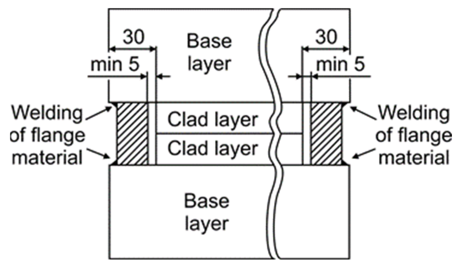
Carbon steel plates with dimensions of 2160 mm × 2100 mm × 60 mm and 316L stainless steel plates of 2060 mm × 2000 mm × 20 mm were prepared for hot-roll bonding, as shown in Table 2. The contact surfaces were shot-blasted to obtain Sa3 quality according to the Standard ISO 8501-1 [25], and additionally ground with grinding paper of grit size P80. Two pairs of plates were assembled into a symmetrically built package. The contact surface between both stainless steel plates was coated with a metal-oxide-based separating agent, so that both halves of the sandwich could be separated after roll bonding. Then, the edges were sealed by manual multi-pass GMAW welding, as shown in Figure 1. No preheating was needed, due to the relatively low carbon content of the base layer and flange material. The low-alloy solid wire SG3 was used for welding. An exhaust hose was installed for vacuuming the contact surfaces inside the package. The space between the plates was vacuumed to the absolute pressure of less than 1.0 mbar to prevent oxidation of the bonding surfaces during hot rolling. After vacuuming, the hose was sealed by remelting it manually with the GTAW process.
Table 2.
Dimensions of the plates assembled into the package.
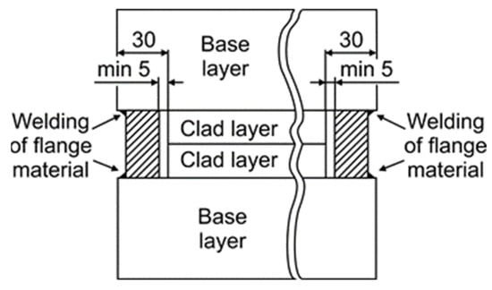
Figure 1.
Schematic presentation of the package assembly; (units are in mm).
Prior to the roll bonding, the packages were preheated in a pusher-type furnace –Ebner CQ9 (Ebner Industrieofenbau GmbH, Leonding, Austria) to 1240 °C for 130 min. The thickness was reduced on a four-stand mill–SMS QPM2500 (SMS Group, Lienz, Austiria), where two work rolls between two supporting roles were used for the deformation, and, hence, bonding operation. The capacity of the mill was 6000 t and the rolling speed was 1 m/s. The thickness was reduced in a total of 9 passes, with a maximum reduction of 33 mm in the first pass, when the temperature was almost equal to the furnace temperature. The reduction in the first pass was limited by the capacity of the mill. One of the parameters that limited the reduction ratio in the first pass was the torque on the work roll rotors. The second one was the normal force in the plate mill stands. A minimum reduction of 2 mm was applied in the last pass. A very low deformation is typically applied to the package in the last passes to achieve the thickness tolerances of the plate. The total reduction ratio was 80%, and the thickness reductions in the individual passes are summarized in Table 3.
Table 3.
Thickness reduction in individual passes.
The final thickness of the clad plate was 16 mm, where the clad layer was around 4 mm thick and the base layer was around 12 mm thick. The clad plates were inspected using ultrasound equipment Krautkrämer USM 100 (Krautkramer GmbH, Hurth, Germany). After that, 200 mm × 200 mm pieces were cut from the clad plate for heat treatment and manufacturing of test specimens for the intended investigations. The heat treatment consisted of solution annealing at 1040 °C for 1 h, and water quenching to improve resistance against intergranular corrosion and achieve the usual delivery condition of 316L stainless steel.
2.3. Methods
Before taking samples from the clad plate, ultrasound testing was carried out to check the soundness of the bond according to ASTM A 578/A 578M-07 [26] and A264 12(2019) [27].
After the heat treatment, the Brinell hardness was measured according to ISO 6506-1 [28] with a WPM Leipzig PSW 300 hardness tester (VEB Werkstoffprüfmaschinen Leipzig, Leipzig, German democratic republic; now WPM Werkstoffprüfsysteme Leipzig, Leipzig, Germany).
A Nikon Epiphot 300 optical microscope (Nikon, Tokyo, Japan) equipped with an Olympus DP-12 digital camera (Olympus, Boston, MA, USA) was used for investigations of the microstructures. For other investigations, a Leica Wild M10 light microscope (Leica microsystems, Wetzlar, Germany) and a Scanning Electron Microscope (SEM) FEI Quanta 3D, were used (FEI Company, Hillsboro, OR, USA; now Thermo Fisher Scientific, Waltham, MA, USA). Classic metallographic preparation was applied for the inspection of the microstructures: grinding with papers P80-P2500 (grit numbers according to ISO 6344-3:2013 [29], followed by polishing with 1.0 μm alumina and etching with two different etchants. To reveal the microstructure of the S355 base layer, etching was used for 10 s with 3% nital according to ISO/TR 16060:2003 [30]. After taking photos of the S355 microstructure, the sample was etched for 10 s with vilella according to ASTM E407-07 [31] to reveal the microstructure of the 316L clad layer.
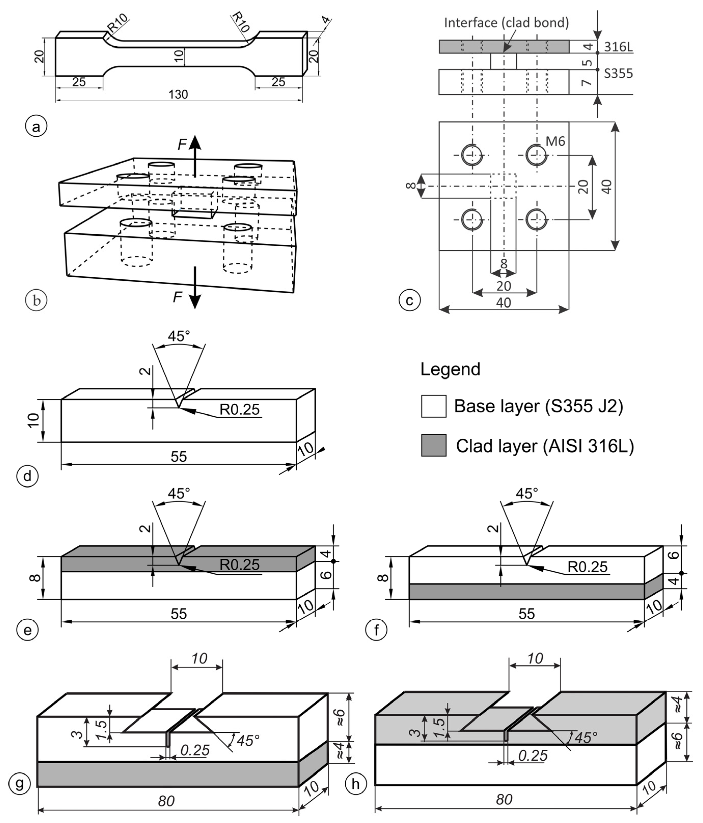
Three test specimens of each type were used for all the mechanical tests. Tensile tests of the base material S355 and the clad material 316L were performed on a serservo-hydraulic 559/594 universal testing machine (Amsler Prüfmaschinen A.G., Merishausen, Switzerland—now Amsler Prüfsysteme, Neftenbach, Switzerland), according to the Standard EN ISO 6892-1, method B [32]. Standard short test specimens were used, with a 10 mm × 4 mm cross-section, Figure 2a, cut in the rolling direction. The tests were performed before rolling and in the final condition. One set of test specimens was machined entirely from the base plate S355; the other entirely from the clad layer 316L. For the tensile tests of the clad bond, unique test specimens were designed, as shown in Figure 2b,c, which were attached to the testing machine with M6 bolts.
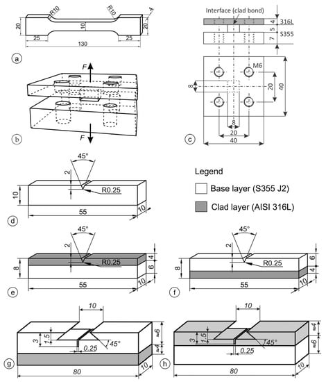
Figure 2.
(a) Geometry of the standardized tensile test specimen; (b) tensile specimen for clad joint tensile testing—3D sketch; (c) crawing with dimensions; (d) ISO-V Charpy test specimen made entirely of S355; (e) ISO-V Charpy specimen notched in the clad layer; (f) ISO-V Charpy specimen notched in the base layer; (g) SENB specimen notched in the base layer; (h) SENB specimen notched in the clad layer; (all units are in mm).
The Instrumented Charpy impact tests were performed with an Amsler RPK300 Charpy pendulum (Amsler Prüfmaschinen A.G., Merishausen, Swiss—now Amsler Prüfsysteme, Neftenbach, Switzerland) with a data acquisition rate of 4 × 10⁶ readings per second, according to Standard ISO 148-1 [33]. Standard ISO-V test specimens 10 mm × 10 mm × 55 mm were used, one set with a V-notch in the base material S355, and the other set with the notch in the 316L steel, as shown in Figure 2d–f.
Fracture toughness tests were carried out according to the ASTM E1820-20 [34] Standard, using w = b single-edge notched beam (SENB) test specimens 10 mm × 10 mm × 80 mm. The geometry of the test specimens is shown in Figure 2. The first group of the SENB test specimens had a notch in the base layer, as shown in Figure 2g. Three test specimens were tested with the crack tip 0.635 mm, 0.735 mm, and 0.993 mm away from the bond line. The second type of test specimens, as shown in Figure 2h, had the notch in the clad layer. Pre-fatigue and post-fatigue for stable crack marking was carried out on the RUMUL Cractronic machine (RUMUL, Schaffhausen, Switzerland), while the SENB test was performed on the 10 kN Smitweld TTU 2002 machine (Smitweld b.v., now Lincoln Smitweld b.v., Nijmegen, The Netherlands).
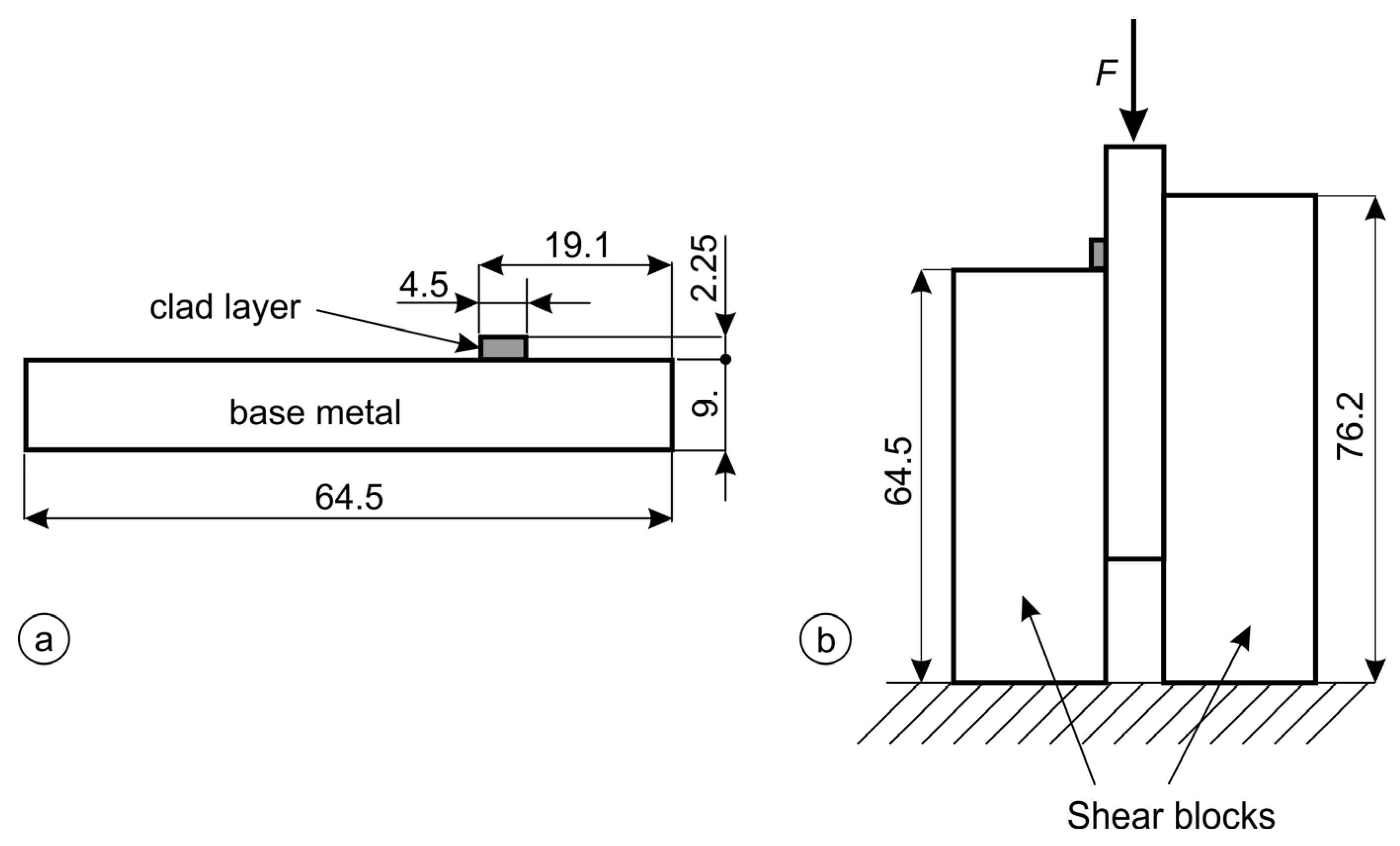
Shear tests were performed on a universal testing machine, Zwick Roell Z600 (Zwick Roell Group, Ulm, Germany), according to Standard ASTM A264-12 [27]. A standardized tool was mounted on the testing machine, and standard test specimens were machined, with a thickness of 9 mm on the base plate side, as shown in Figure 3.

Figure 3.
Shear test: (a) test specimen; (b) test assembly; (all units are in mm).
3. Results and Discussion
3.1. Ultrasonic Testing
According to ASTM A 578/A 578M [26], the plate fulfills the requirements for quality Level A if there is no area where one or more discontinuities produce a continuous total loss of back reflection accompanied by continuous indications on the same plane (within 5% of plate thickness) that cannot be encompassed within a circle whose diameter is 75 mm or 1/2 of the plate thickness. According to ASTM A264 [27], the cladding is unbonded if there is a complete loss of back reflection accompanied by an echo indication from the plane of the interface of the clad and backing steel. For Class 1 quality, single unbonded areas up to 25 mm are allowed, and the total unbonded area must not exceed 1% of the total cladded surface area.
No disallowed defects were detected. Consequently, the examined plate meets the requirements of both Standards for the highest quality level/class.
3.2. Macro- and Microstructure
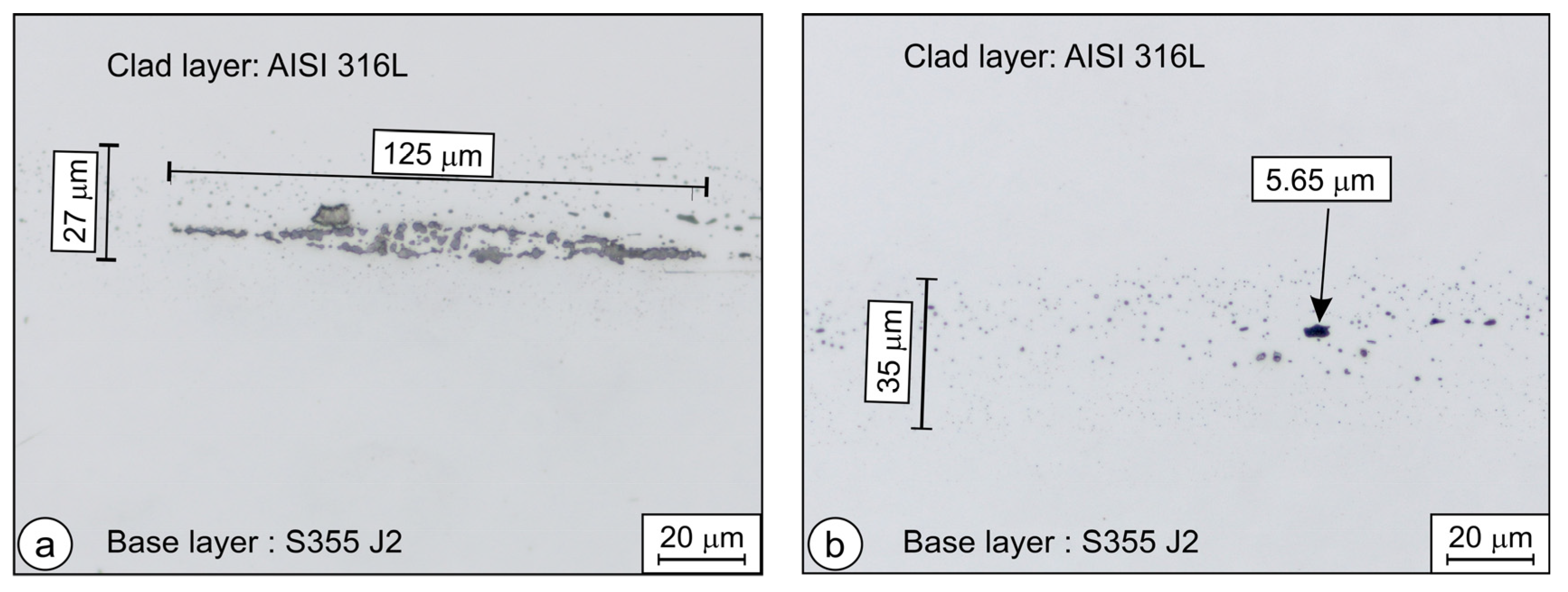
Microscopy revealed that the interface was not entirely oxide-free. The largest detected defect (oxide-rich area) on the interface measured approximately 0.125 mm, as shown in Figure 4a. Most likely, this defect can be attributed to insufficient cleaning prior to welding the package. Nowhere else were such concentrations of oxide particles discovered. Mostly, much smaller concentrations of oxide particles could be observed on the interface, as shown in Figure 4b.
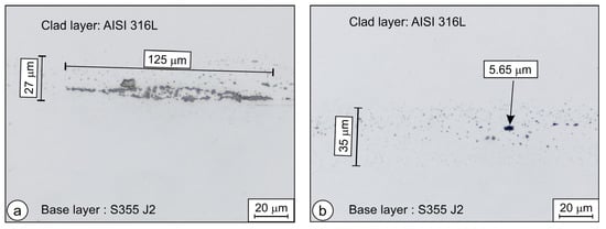
Figure 4.
Thin oxide interface between two layers: (a) oxide-rich area on the interface; optical micrograph, and (b) oxide particles on the bond line—typical concentration and size distribution.
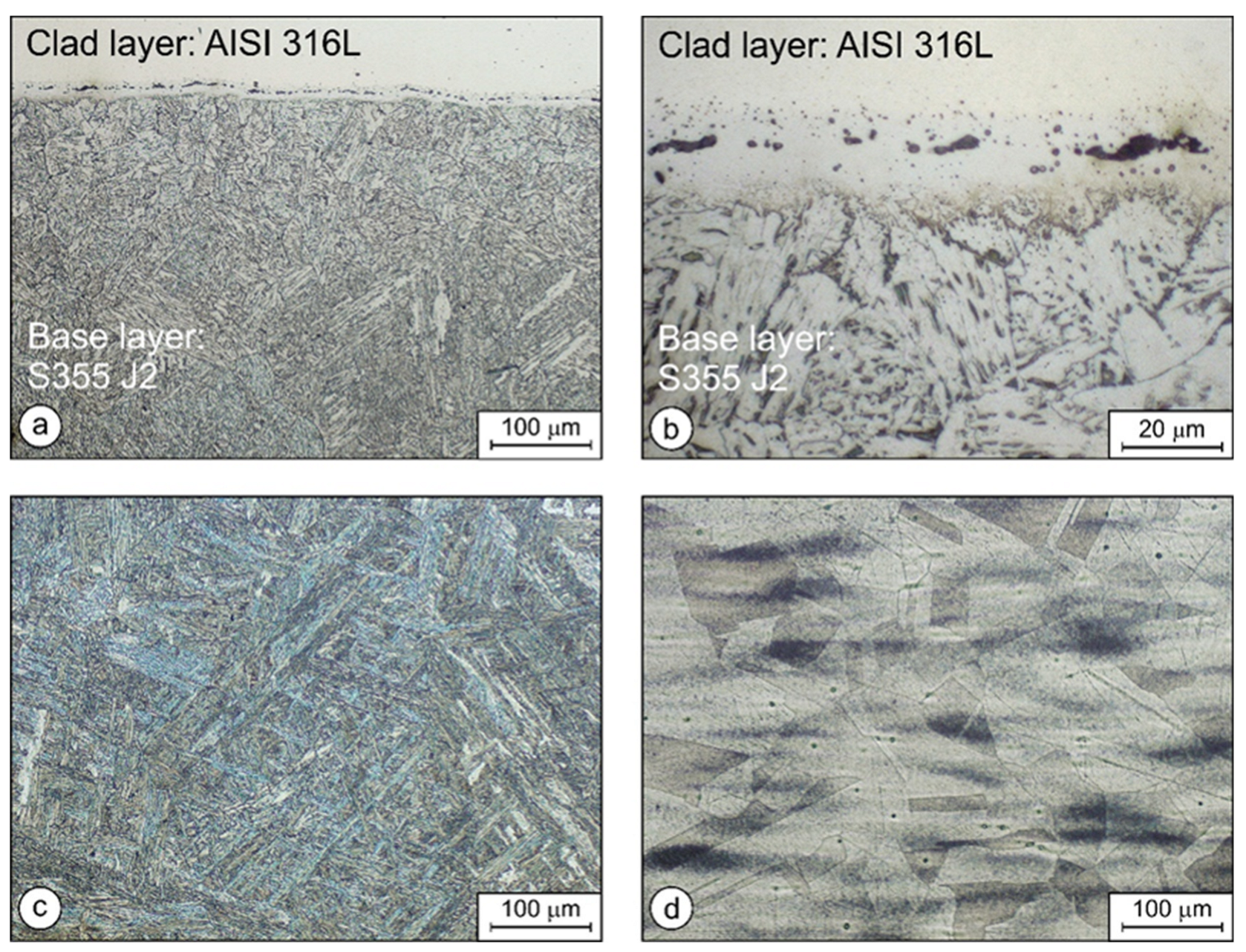
Figure 5a–c present the microstructure of the base plate S355. In Figure 5a,b, the clad layer and the presence of oxides on the interface are also visible. In Figure 5c, the coarse, predominantly bainitic microstructure can be observed, where the lath length is between 75 µm and 125 µm. That the predominant constituent must be bainite can be concluded from the measured hardness of 248 HB 2,5/187.5, and the CCT diagram [35]. In addition, the microstructure of the AISI 316L clad layer is coarse-grained, as shown in Figure 5d, as expected, because austenitic steels do not undergo any phase transformations upon quenching.

Figure 5.
Microstructure of the clad weld: (a) clad weld (200×); (b) clad weld (1000×); (c) base layer—S355 J2 (200×); (d) clad layer AISI 316L (200×).
3.3. Tensile Tests
The tensile tests were performed for the base and the clad layer in the rolling direction before and after the cladding process. Namely, the base and clad layer materials were hardened differently. Due to their chemical compositions, quenching affected only the base layer S355, while the clad layer of 316L remained soft. The results of the tensile tests in the rolling direction and thickness direction are summarized in Table 4.
Table 4.
Tensile properties of the base- and clad layers and tensile strength of the bond.
The yield stress and the tensile strength increased in the rolling direction of both layers. The yield and tensile strength of the S355 layer increased by 73% and 38%, respectively. The increase was due predominantly to quenching. The yield strength and tensile strength of the 316L layer increased by 27% and 5%, respectively. In the case of 316L, the increase was due to plastic deformation and recrystallization.
The tensile test in the thickness direction revealed that the strength of the clad weld achieved by the hot-bonding process in the thickness direction was only 155 MPa. A strength of 155 MPa appears low, but for the operation of products made of clad plates, the tensile strength of the bond is much less important than the shear strength.
3.4. Shear Tests
The values of the shear strength of the clad joint are presented in Table 5. The test specimens taken from the oxide-rich areas exhibited an average shear strength of 178 MPa, the lowest measured value being 172 MPa. The shear strength of specimens taken from the areas with a typical concentration of oxide particles exhibited much higher shear strength; on average, 363 MPa. According to ASTM A264 [27], the minimum shear strength should be 140 MPa. This means that, even in locations with high concentrations of oxide particles, the requirements of ASTM A264 were met.
Table 5.
Shear strength according to the ASTM A264 Standard.
3.5. Instrumented Charpy Impact Test
3.5.1. Test Specimens after the Test
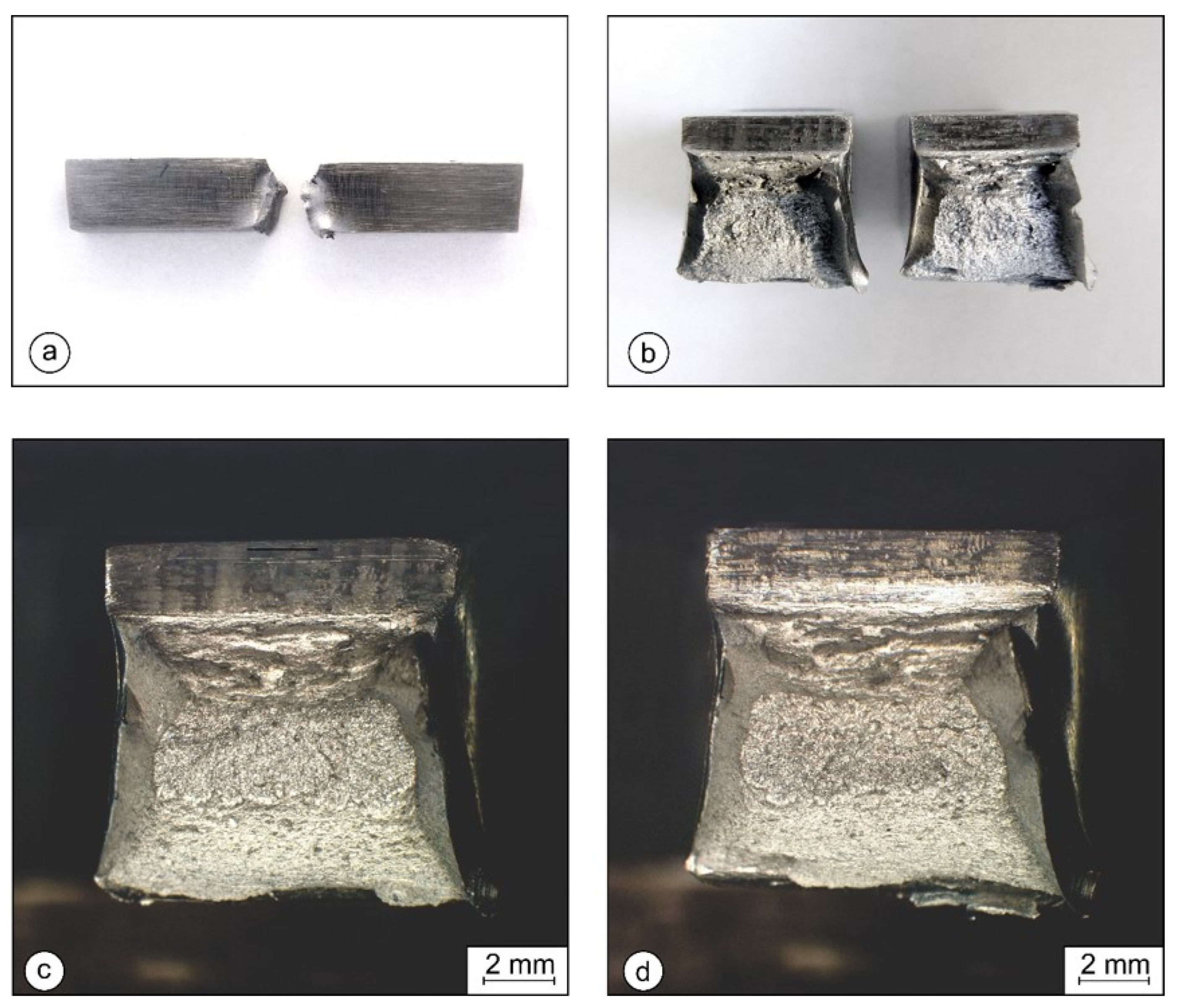
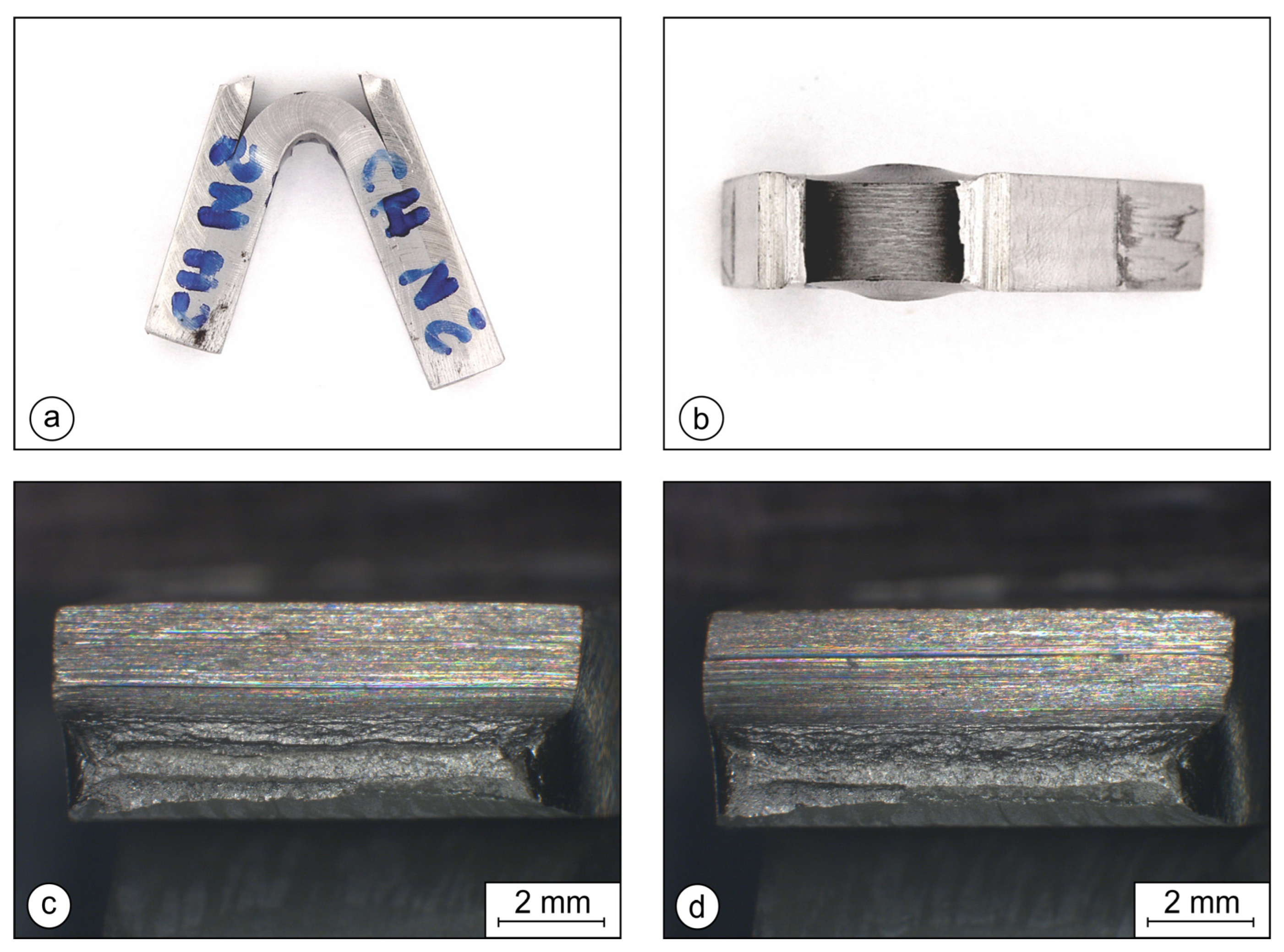
Figure 6 shows the test specimen made entirely of the base layer S355. The fracture surfaces in Figure 6c,d show a relatively ductile fracture (considering that the material was quenched).

Figure 6.
Broken Charpy specimen made entirely of base layer S355: (a) side view; (b) photo of the fracture surfaces; (c,d) fracture surfaces of both halves (optical microscope).
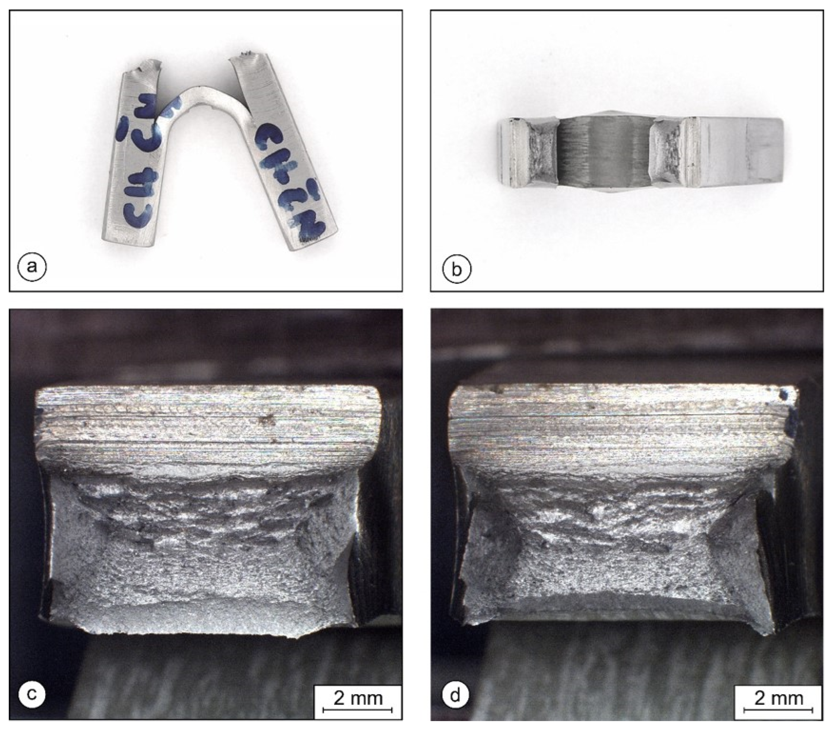
Figure 7 shows a specimen with the V-notch in the base layer. The crack propagated through the base layer towards the interface. When it reached the interface, the crack split, changed the direction of propagation, and continued in the plane of the interface, causing partial delamination of the test specimen.
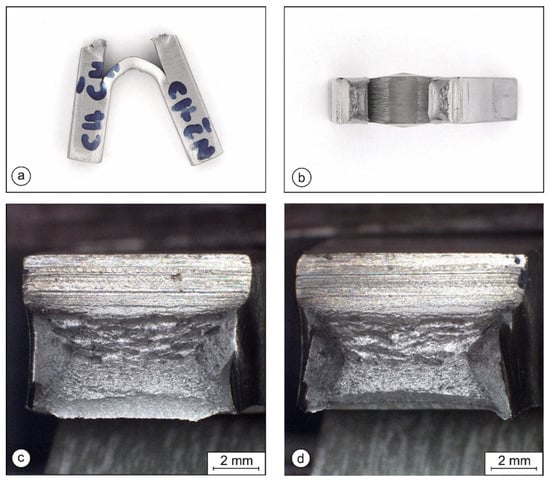
Figure 7.
Broken Charpy specimen with the notch in the base layer S355: (a) side view; (b) top view; (c,d) fracture surface of the base layer S355 (optical microscope).
Figure 8 shows a specimen with the V-notch in the clad layer 316L. The crack propagated through the clad layer towards the interface. When it reached the interface, the crack split, changed the direction of propagation, and continued in the plane of the interface, causing partial delamination of the test specimen.
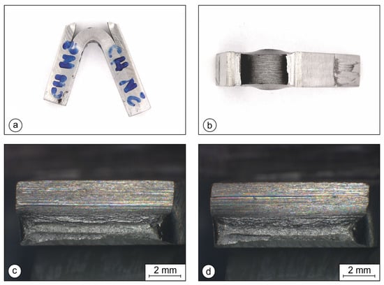
Figure 8.
A test specimen with the notch in the clad layer 316L: (a) side view; (b) top view; (c,d) fracture surfaces of the clad layer 316L (optical microscope).
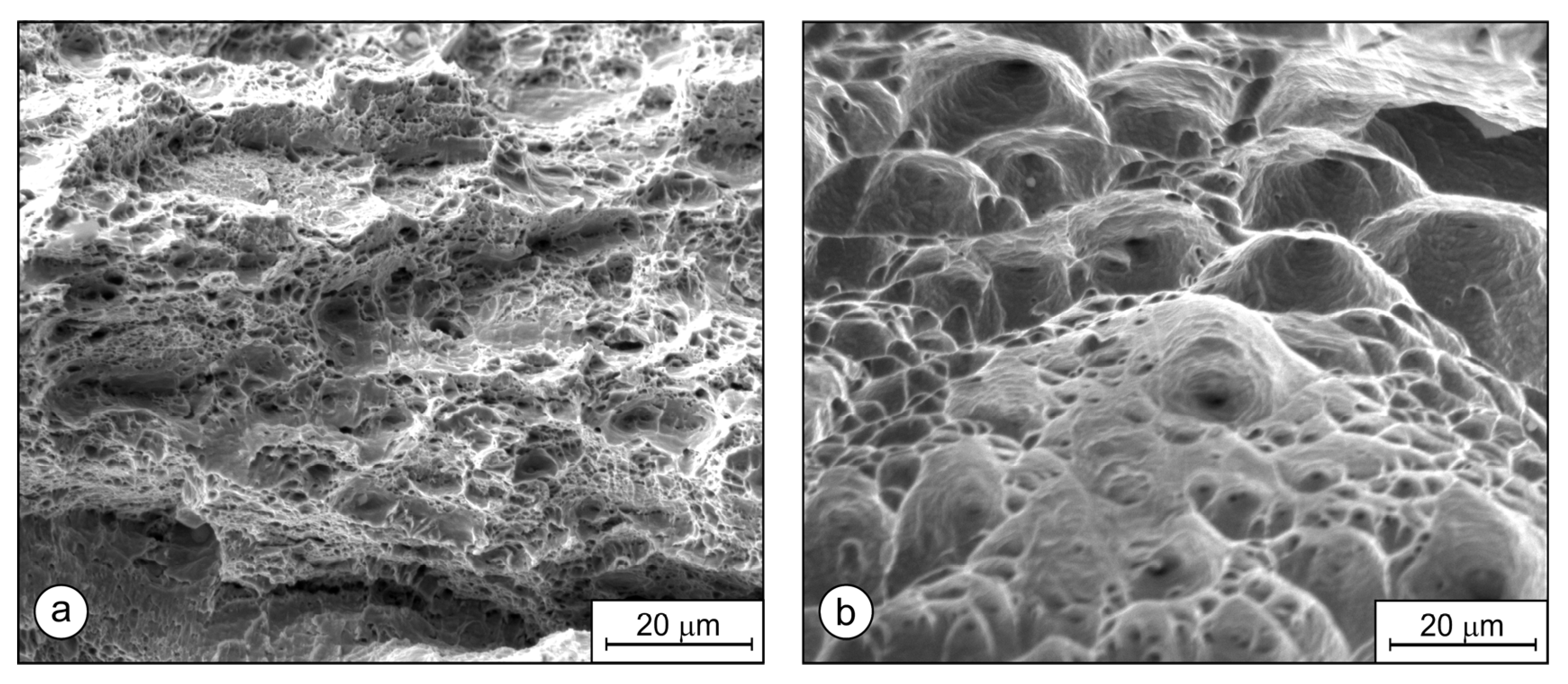
Figure 9 shows SEM images of the fracture surfaces in the base layer (Figure 9a) and in the clad layer (Figure 9b). A comparison of the images reveals that the behavior of the clad material 316L was more ductile than that of the base layer S355.

Figure 9.
Fracture surface, SEM images: (a) base layer S355; (b) clad layer 316L.
Regardless of where the crack initiated, it only propagated through the layer with the V-notch, and did not cross the interface between the layers. Consequently, clad plates behave differently than homogeneous plates made of only one material. The interface acts as a barrier for crack propagation through the composite-plate thickness, and redirects the crack into a direction parallel to the mechanical load. Such cracks are much less dangerous than cracks propagating in the direction of the material’s thickness. In the case of pressure vessels or pipelines, where hot-rolled clad plates are usually used, such behavior can be beneficial, especially in cases when the crack initates in the thinner stainless layer, and the thicker non-alloyed layer is thick enough to withstand the mechanical load. Consequently, the lifetime can be extended.
3.5.2. Results of the Instrumented Charpy Tests
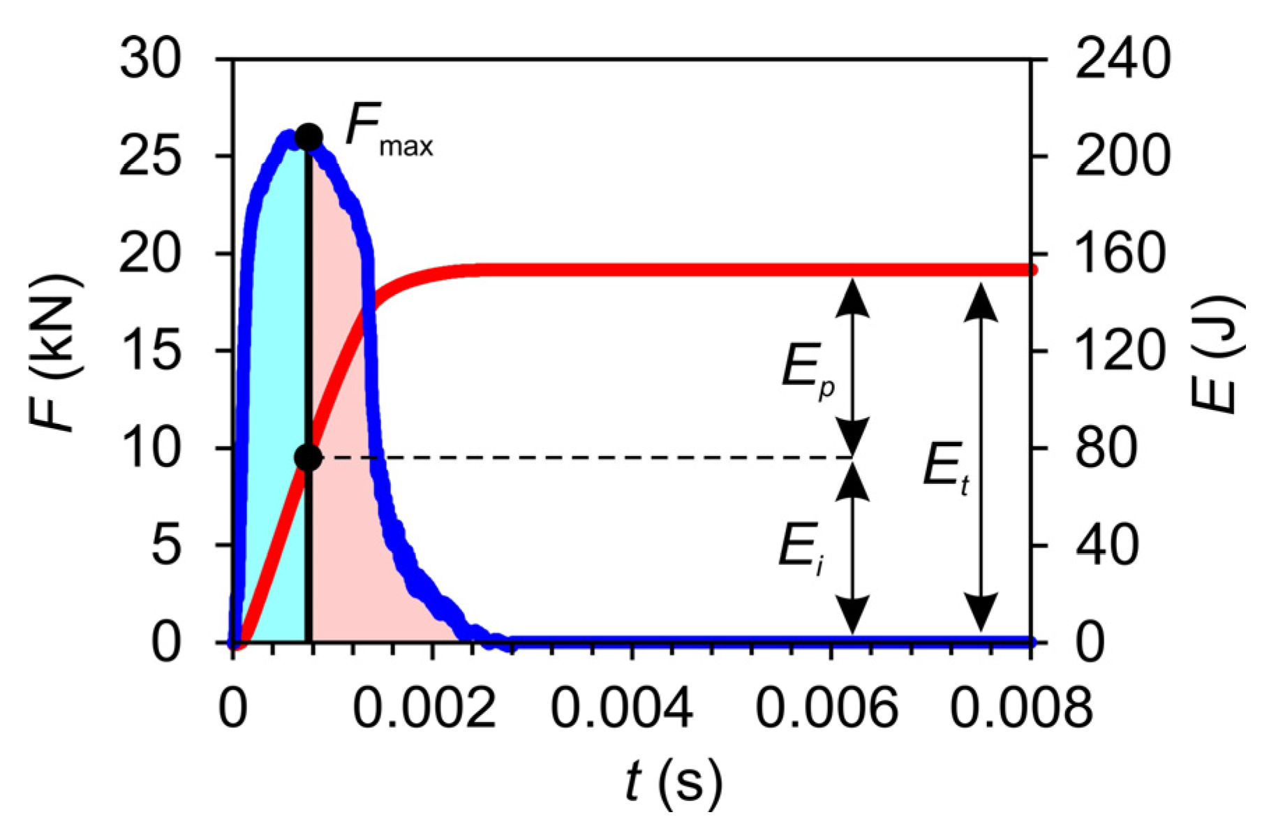
Usually, two different curves are recorded during the instrumented Charpy test: the curve of force vs. time (blue) and the curve of absorbed energy vs. time (red). If both curves are drawn in the same diagram, the total absorbed energy can be split into energy absorbed for initiation of the crack Ei and energy absorbed for crack propagation Ep. The procedure is explained in Figure 10.
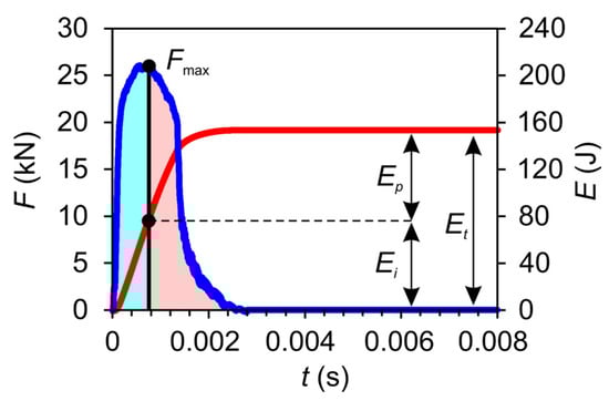
Figure 10.
Spliting of the total absorbed energy into energy absorbed for initiation of the crack Ei and energy absorbed for crack propagation Ep.
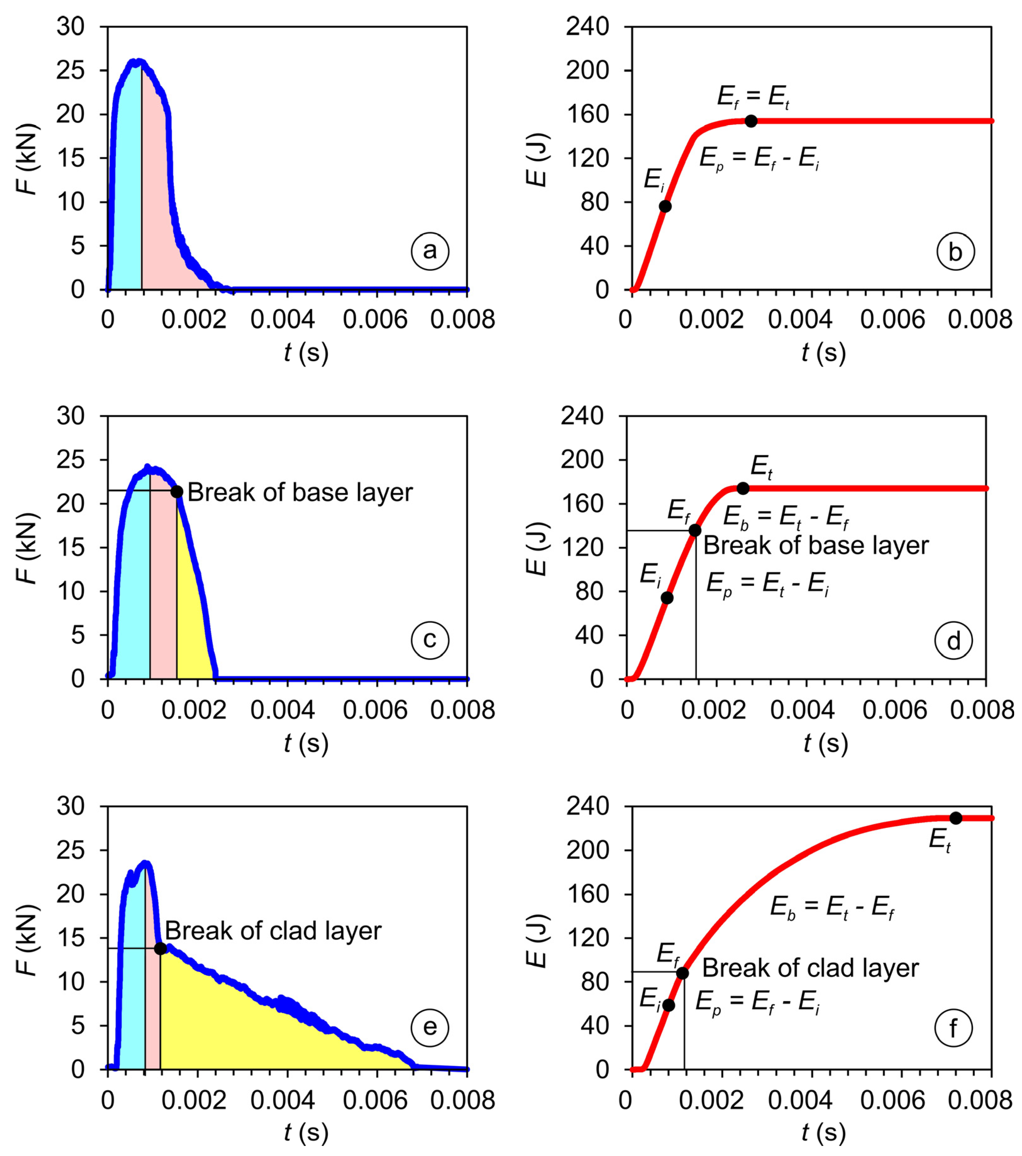
If the crack propagation is stable (a more or less ductile fracture), no sudden changes are present in the incline of the force vs. time curve. If a sudden change in the incline is present, it can only be explained by break of the notched layer. Points of layer break can be identified in this way. Nevertheless, in the case of Figure 11c, the change in incline is hardly noticeable. Therefore, we always record also the noise vs. time curve, because aligning the noise vs. time curve with other recorded curves always enables reliable determination of the characteristic points.
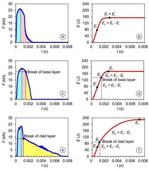
Figure 11.
Results of instrumented Charpy tests: (a,b) base layer; (c,d) cladded weld with a notch in the base layer; (e,f) cladded weld with a notch in the clad layer.
The energy for initiation Ei was needed for crack initiation at the bottom of the V-notch. After initiation, the energy for propagation Ep was required for further crack propagation. At the end, when the crack had reached the interface between the layers, delamination occurred, and energy Eb was needed for further bending of the second material to finish the test. The energy for fracture Ef was obtained by adding the energy for initiation Ei and the energy for propagation Ep.
The results of the instrumented Charpy tests are summarized in Table 6. The diagrams are presented in Figure 11. The energies absorbed for initiation of the crack Ei are marked with the blue color, the energies absorbed for crack propagation Ep with red, and th energies absorbed for the bending of the specimen Eb with yellow.
Table 6.
Results of the instrumented Charpy test.
The curves of force vs. time (blue) are presented in Figure 11a,c,e, and the curves of absorbed energy vs. time (red) are presented in Figure 11b,d,f).
Figure 11a,b shows the curves for a test specimen made entirely of S355, Figure 11c,d for a cladded specimen with the ISO-V notch in the base layer, and Figure 11e,f for a specimen with the notch in the clad layer. The black dots mark crack initiation, the end of crack propagation, and the end the of test (the moment the specimen was pulled through the support blocks).
Because the base material S355 in the test specimens consisting of both layers was 6 mm thick, while the 316L layer was only 4 mm thick, higher force and energy were needed to break the base layer. A similar situation was seen for bending. The bending of the thicker S355 layer required more energy than the bending of the thinner 316L layer. The total absorbed energy was higher when the V-notch was in the clad layer (316L). The total absorbed energy of two-layer test specimens was always higher than the total energy for S355 specimens and that of 316L steel (about 100 J if the tensile properties were very similar to our clad layer [36]). The results indicate that clad plates should exhibit higher resistance against impact bending loads than conventional 316L plates.
3.6. Fracture Toughness
ASTM E399 [37] can be used in the case of homogeneous brittle materials, but for the testing of inhomogeneous ductile materials, ASTM E1820 [34] is applicable. ASTM E1820 can be used for the testing of materials where the crack propagates through different areas exhibiting different mechanical properties, like welds (different HAZ subzones, or different weld passes in the weld metal). ASTM E1820 is, therefore, also applicable for clad plates, and was used in our work.
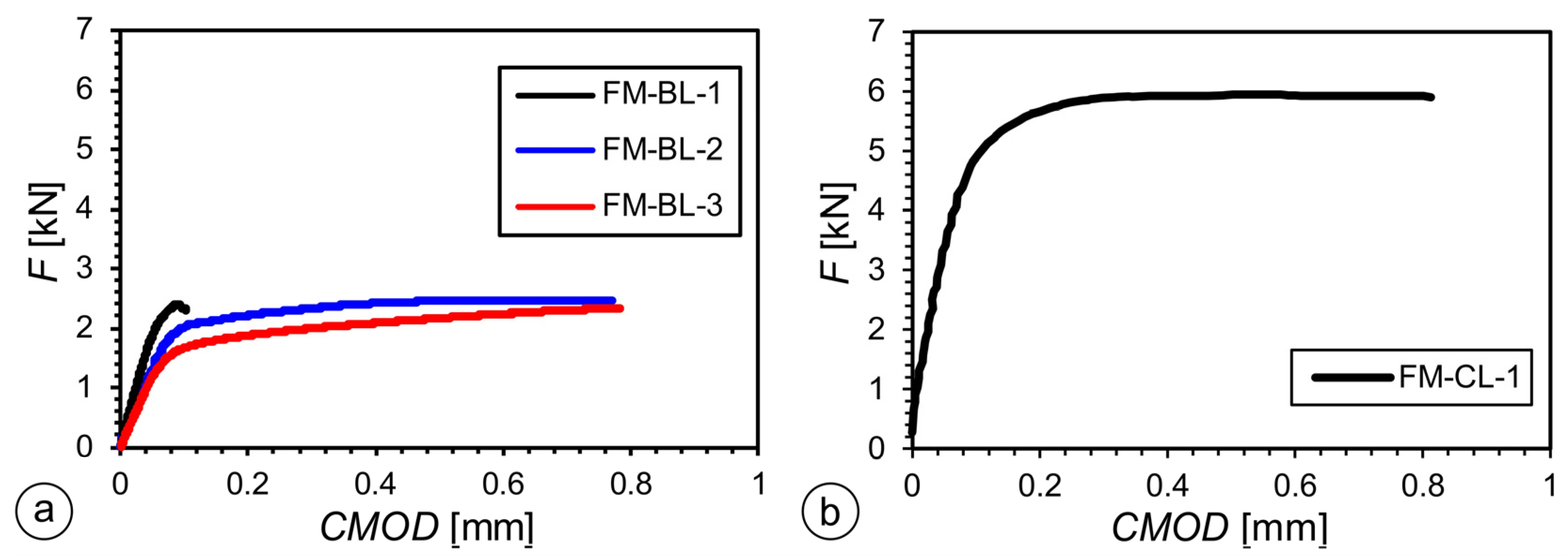
Figure 12 shows the recorded F-CMOD curves (CMOD = crack mouth opening displacement). Specimens notched on the base layer side are shown in Figure 12a, and Figure 12b shows the specimens notched on the clad layer side. Among the specimens notched in the clad layer, valid results were obtained only with one specimen, while, for the other two specimens, due to pop-in and tunneling of the crack, the results were not valid. Opening the crack in S355 required significantly lower forces than opening the crack in 316L. This is predominantly because the initial cracks in S355 were longer, and the remaining cross-section larger than in the test specimens notched on the 316L side. The tests were stopped as soon as delamination of the bond occurred. The fracture toughness K1c could not be determined due to delamination. The stress intensity factor KQ at delamination was given instead. The results of the SENB tests are summarized in Table 7.
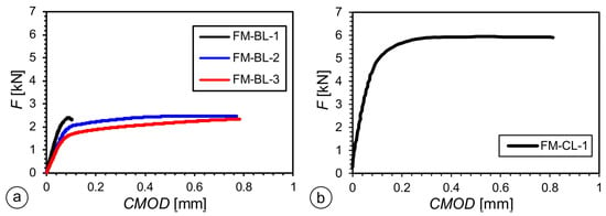
Figure 12.
F-CMOD graphs of SENB specimens: (a) crack tip in the base layer; (b) crack tip in the clad layer.
Table 7.
Results of the SENB tests.
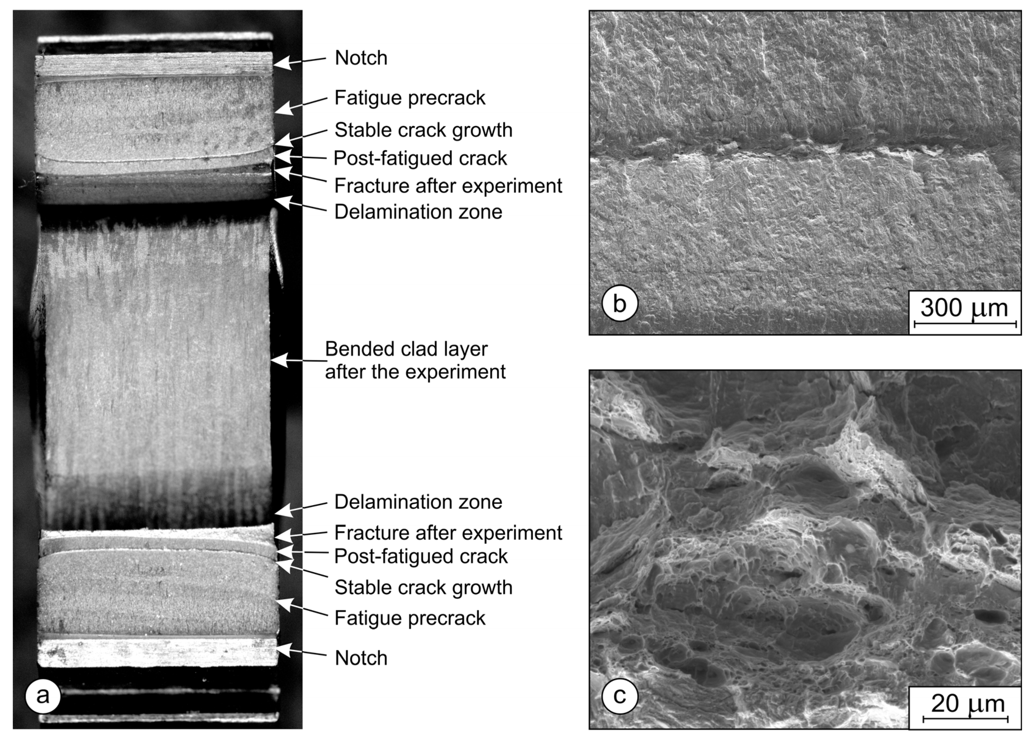
In the test specimen FM-BL-1, notched on the base layer side, delamination occurred soon after a very small CMOD. Post-fatigue followed to mark the position of the crack tip at the end of the SENB experiment. Finally, to enable measuring of the crack propagation during the SENB test, the specimen was subjected to further three-point bending, which caused the rupture of the base layer, further delamination, and bending of the clad layer. The crack was not able to cross the interface and initiate in the clad layer, neither during post-fatigue nor during the final three-point bending.
In general, the test specimen FM-BL-1 behaved just like the others. Therefore, images are presented only for the other test specimens.
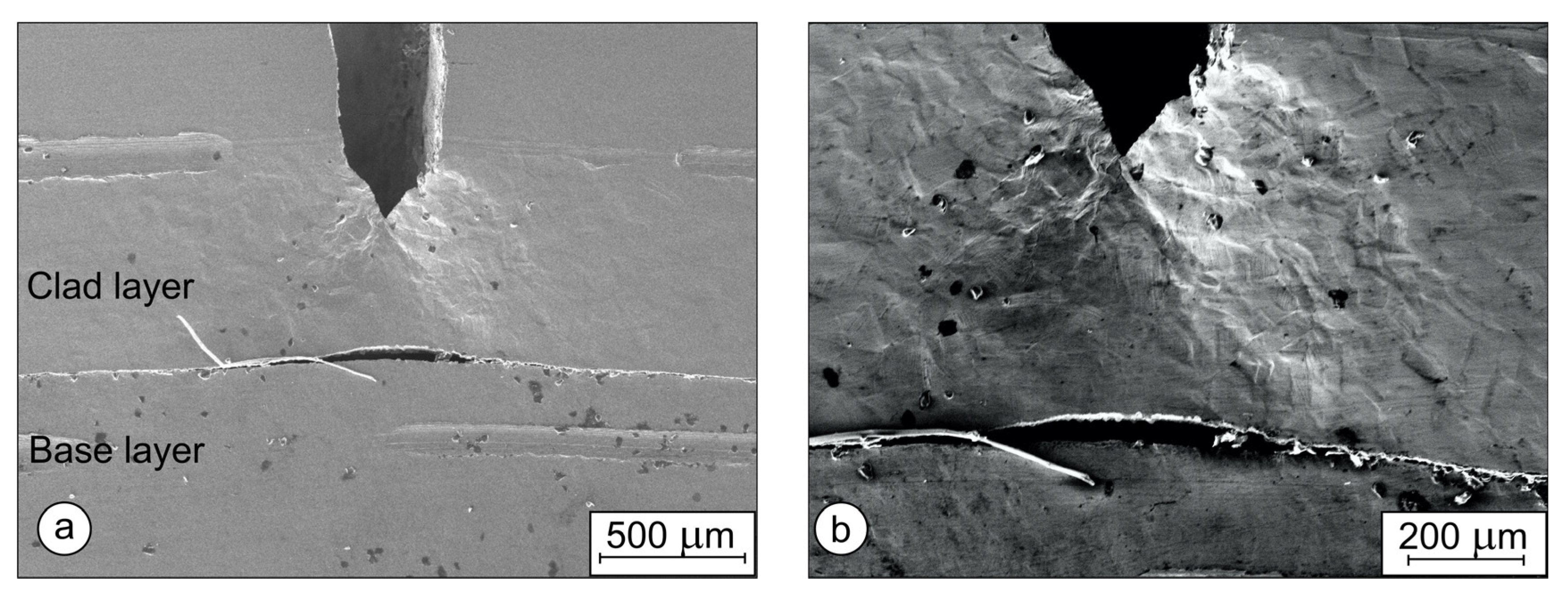
The SEM images of the side surfaces of FM-BL-2 are presented in Figure 13, Figure 14, Figure 15 and Figure 16. Figure 13 and Figure 14 show the left and right sides of the specimen, respectively. Figure 13a shows that, on the left side, during post-fatigue, the crack tip did not reach the interface. A plastic zone is visible ahead of the crack tip. Figure 14b shows the plastic zone ahead of the crack tip at higher magnification. Slipping bands can be observed in the individual grains in the vicinity of the crack tip.
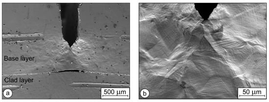
Figure 13.
The left side of the SENB specimen FM-BL-2, SEM images: (a) crack tip and delamination; (b) crack tip and plastic zone ahead of the crack tip.
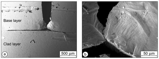
Figure 14.
The right side of the SENB specimen FM-BL-2, SEM images: (a) crack tip and delamination—the crack reached the interface between the base and the clad layer; (b) plastic zone near the crack tip.
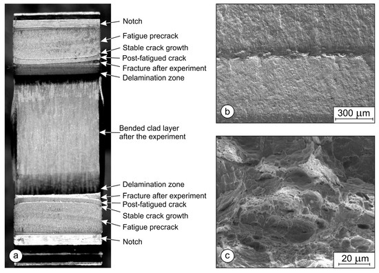
Figure 15.
Fractured SENB specimen FM-BL-3: (a) fractured surfaces, delaminated zone, and bent clad layer (optical microscope); (b) stable crack growth (SEM image); (c) ductile stable crack growth (SEM image).
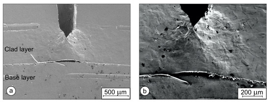
Figure 16.
The left side of the SENB specimen FM-CL-1, SEM images: (a) crack tip and delamination between the bond of the clad and the base layer; (b) crack tip and plastic zone ahead of the crack tip and delamination zone of the bond.
Figure 14a shows the right side, where the crack reached the interface during post-fatigue. However, on this side, the post-fatigue could not drive the crack across the interface either. Figure 14b shows slipping bands in the individual grains in the plastic zone.
In specimen FM-BL-3, during post-fatigue, the crack propagated more evenly, but also, in this case, stopped before reaching the interface, and did not initiate in the clad layer. The fracture surfaces are depicted in Figure 15. Figure 15a shows both the fracture surfaces and the bent clad layer. The SEM micrograph in Figure 15b shows the stable crack propagation area during the SENB test (the darker area approximately in the middle of the micrograph), the pre-fatigue fracture surface above, and the post-fatigue fracture below it. In Figure 15c, distinct dimples can be observed, confirming the stable crack growth and ductile nature of fracture during the SENB test.
Figure 16 and Figure 17 show the left and right sides of the specimen FM-CL-1 notched on the clad layer, respectively. Figure 16a shows that, during post-fatigue, the crack tip on the left side stopped before reaching the interface, while, on the right side, Figure 17a, it stopped after reaching the interface. In Figure 16b and Figure 17b, a large plastic zone around the crack tip can be observed at higher magnification.
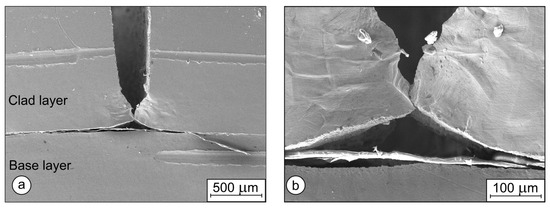
Figure 17.
The right side of the SENB specimen FM-CL-1, SEM images: (a) crack tip and delamination between the bond of the clad and the base layer; (b) crack tip, plastic zone ahead of the crack tip and delamination zone of the bond.
In all cases, the stress intensity factor (SIF) KQ and J integral exceeded the energy necessary for delamination of the hot-rolled bond between the base and the clad layer. Delamination of the bond occurred at that moment. Consequently, the SIF and J integral were reduced, and the crack propagation stopped. Because the strength of the bond between the base and clad layer in the thickness direction was low, just 155 MPa, during the SENB tests, only a short propagation of the cracks was possible before the delamination. Additionally, the SIF was too low during the subsequent post-fatigue to drive the cracks across the interface. Upon further bending after the occurrence of delamination, the available energy was not used for crack propagation across the interface, but for further delamination and bending of the layer below the interface.
Such behavior can, in some cases, be useful in practice, like in the case of pressure vessels and pipelines for aggressive media, where hot-rolled bond plates are used typically. In such cases, cracks propagating from the inner side (in the clad layer) can be stopped before the remaining load-bearing cross-section becomes too small to prevent a sudden rupture. After the crack reaches the interface, the unalloyed outer layer is exposed to corrosion. However, due to the stopping of the crack, the final rupture is delayed, because corrosion is usually slower than the crack propagation of long cracks, and the probability increases of detecting the damage at routine inspections before rupture.
4. Conclusions
Hot-roll-bonded clad steel plates, consisting of a 12 mm thick base layer of S355 steel and a 4 mm thick clad layer of 316L stainless steel, were produced in an industrial environment.
Ultrasonic inspection revealed no unbonded areas.
Metallographic examination of the solution-annealed and water-quenched clad plate showed that a relatively low concentration of oxide particles prevailed at the interface between the S355 and 315L layers. The microstructure was equiaxial in the 316L clad layer and predominantly bainitic in the S355 base layer.
The tensile strengths Rm of the S355 layer and 316L layer were 719 MPa and 567 MPa, respectively. Using specially designed non-standard test specimens, the tensile strength was determined of the bond in the direction perpendicular to interface Rm = 155 MPa.
The shear strength of the bond in areas with low oxide particle concentration was 363 MPa, and in areas with high concentration of oxide particles was 178 MPa—still well in excess of the ASTM A264 minimum strength requirement of 140 MPa.
Charpy impact tests at room temperature were performed with ISO-V standard test specimens. One group was notched in the base layer; the other in the clad layer. In none of the tests could the crack cross the interface. In each case, only the notched layer broke, and partial delamination of the bond occurred, while the layer below the interface was only bent. The impact energies were higher than 170 J, which is more than those of each material alone.
The results of the SENB tests were similar. The crack could not propagate across the interface. Delamination always occurred before the crack could reach the interface, and the tests were terminated. In addition, subsequent post-fatigue and final braking by three-point bending could not drive the crack across the interface. Instead, delamination continued, and the layer behind the interface was only bent. Fracture toughness K1c could not be determined due to the delamination.
Author Contributions
Conceptualization, E.B., A.S. and T.V.; methodology, E.B., A.S. and T.V.; validation, E.B., A.S., G.L., J.P. and T.V.; formal analysis, E.B., A.S. and T.V.; investigation, E.B., A.S., F.S., G.L., J.P. and T.V.; writing—original draft preparation, E.B. and G.L.; writing—review and editing, E.B., G.L. and T.V.; visualization, A.S., G.L. and T.V.; supervision, T.V. and J.P.; project administration, T.V. and G.L.; funding acquisition, A.S. and T.V. All authors have read and agreed to the published version of the manuscript.
Funding
This research was funded by Slovenian Research Agency, projects BI-BA/19-20-036 and BI-AT/18-19-016.
Data Availability Statement
We will not share research data.
Conflicts of Interest
The authors declare no conflict of interest.
References
- Zhu, Z.C.; He, Y.; Zhang, X.J.; Liu, H.Y.; Li, X. Effect of interface oxides on shear properties of hot-rolled stainless steel clad plate. Mater. Sci. Eng. A 2016, 669, 344–349. [Google Scholar] [CrossRef]
- Song, H.; Shin, H.; Shin, Y. Heat-treatment of clad steel plate for application of hull structure. Ocean Eng. 2016, 122, 278–287. [Google Scholar] [CrossRef]
- Liu, B.X.; Yin, F.X.; Dai, X.L.; He, J.N.; Fang, W.; Chen, C.X.; Dong, Y.C. The tensile behaviors and fracture characteristics of stainless steel clad plates with different interfacial status. Mater. Sci. Eng. A-Struct. 2017, 679, 172–182. [Google Scholar] [CrossRef]
- Su, H.; Luo, X.B.; Chai, F.; Shen, J.C.; Sun, X.J.; Lu, F. Manufacturing Technology and Application Trends of Titanium Clad Steel Plates. J. Iron Steel Res. Int. 2015, 22, 977–982. [Google Scholar] [CrossRef]
- Fang, J.; Li, Y.Z. Process Optimization for Welding Stainless Steel clad material based on orthotropic bridge plates. Appl. Mech. Mater. 2012, 178–181, 2066–2069. [Google Scholar] [CrossRef]
- Ye, Y.; Zhang, S.J.; Han, L.H.; Liu, Y. Square concrete-filled stainless steel/carbon steel bimetallic tubular stub columns under axial compression. J. Constr. Steel Res. 2018, 146, 49–62. [Google Scholar] [CrossRef]
- Liu, J.G.; Wu, J.; Liu, Q.; Ji, S.; Zheng, X.L.; Wang, F.; Wang, J. Analysis of Cold Composite Sheet Rolling 572 Considering Anisotropic Effect and Position-Dependent Friction Model. Metals 2023, 13, 259. [Google Scholar]
- Li, Y.W.; Liu, H.T.; Wang, Z.J.; Zhang, X.M.; Wang, G.D. Suppression of edge cracking and improvement of ductility in high borated stainless steel composite plate fabricated by hot-roll-bonding. Mater. Sci. Eng. A-Struct. 2018, 731, 377–384. [Google Scholar] [CrossRef]
- Song, J.; Kostka, A.; Veehmayer, M.; Raabe, D. Hierarchical microstructure of explosive joints: Example of titanium to steel cladding. Mater. Sci. Eng. A 2011, 528, 2641–2647. [Google Scholar] [CrossRef]
- Wu, X.M.; Shi, C.G.; Fang, Z.H.; Lin, S.L.; Sun, Z.R. Comparative study on welding energy and Interface characteristics of titanium-aluminum explosive composites with and without interlayer. Mater. Des. 2021, 197, 109279. [Google Scholar] [CrossRef]
- Arab, A.; Guo, Y.S.; Zhou, Q.; Chen, P.W. Joining AlCoCrFeNi high entropy alloys and Al-6061 by explosive welding method. Vacuum 2020, 174, 109221. [Google Scholar] [CrossRef]
- Zhao, H. The Microstructure and Property of a Titanium-Carbon Steel Clad Plate Prepared Using Explosive Welding. Metals 2022, 12, 129. [Google Scholar] [CrossRef]
- Chen, Y.H.; Sun, S.W.; Zhang, T.M.; Zhou, X.W.; Li, S.H. Effects of post-weld heat treatment on the microstructure and mechanical properties of laser-welded NiTi/304SS joint with Ni filler. Mater. Sci. Eng. A 2020, 771, 138545. [Google Scholar] [CrossRef]
- Li, C.A.; Qin, G.L.; Tang, Y.S.; Zhang, B.G.; Lin, S.B.; Geng, P.H. Microstructures and mechanical 589 properties of stainless steel clad plate joint with diverse filler metals. J. Mater. Res. Technol. 2020, 9, 2522–2534. [Google Scholar] [CrossRef]
- Guo, K.; Gou, G.Q.; Lv, H.; Shan, M.L. Jointing of CFRP/5083 Aluminum Alloy by Induction Brazing: Processing, Connecting Mechanism, and Fatigue Performance. Coatings 2022, 12, 1559. [Google Scholar] [CrossRef]
- Rahmatabadi, D.; Pahlavani, M.; Gholami, M.D.; Marzbanrad, J.; Hashemi, R. Production of Al/Mg-Li composite by the accumulative roll bonding process. J. Mater. Res. Technol. 2020, 9, 7880–7886. [Google Scholar] [CrossRef]
- Rahmatabadi, D.; Tayyebi, M.; Najafizadeh, N.; Hashemi, R.; Rajabi, M. The influence of post-annealing and ultrasonic vibration on the formability of multilayered Al5052/MgAZ31B composite. Mater. Sci. Technol. 2021, 37, 78–85. [Google Scholar] [CrossRef]
- Wang, P.J.; Chen, Z.J.; Hu, C.; Li, B.X.; Mo, T.Q.; Liu, Q. Effects of annealing on the interfacial structures and mechanical properties of hot roll bonded Al/Mg clad sheets. Mater. Sci. Eng. A 2020, 792, 139673. [Google Scholar] [CrossRef]
- Rao, N.V.; Reddy, G.M.; Nagarjuna, S. Weld overlay cladding of high strength low alloy steel with austenitic 600 stainless steel—Structure and properties. Mater. Design 2011, 32, 2496–2506. [Google Scholar]
- Rezaii, A.; Shafiei, E.; Ostovan, F.; Daneshmanesh, H. Experimental & theoretical investigation of roll bonding process of multilayer strips by finite element method. J. Manuf. Process. 2020, 54, 54–69. [Google Scholar]
- Liu, B.X.; An, Q.; Yin, F.X.; Wang, S.; Chen, C.X. Interface formation and bonding mechanisms of hot-rolled stainless steel clad plate. J. Mater. Sci. 2019, 54, 11357–11377. [Google Scholar] [CrossRef]
- Zhao, Z.P.; Tang, J.R.; Tariq, N.U.; Liu, H.S.; Liu, H.H.; Ren, Y.P.; Tong, M.; Yin, L.S.; Du, H.; Wang, J.Q.; et al. Effect of rolling temperature on microstructure and mechanical properties of Ti/steel clad plates fabricated by cold spraying and hot-rolling. Mater. Sci. Eng. A 2020, 795, 139982. [Google Scholar] [CrossRef]
- EN 10025-2:2019; Hot Rolled Products of Structural Steels—Part 2: Technical Delivery Conditions for Non-Alloy Structural Steels. European Committee for Standardization: Brussels, Belgium, 2019; pp. 1–41.
- ASTM A240/240M-22A; Standard Specification for Chromium and Chromium-Nickel Stainless Steel Plate, Sheet, and Strip for Pressure Vessels and for General Applications. ASTM International: West Conshohocken, PA, USA, 2022; pp. 1–12.
- International Organization for Standardization. Preparation of Steel Substrates before Application of Paints and Related Products—Visual Assessment of Surface Cleanliness—Part 1: Rust Grades and Preparation Grades of Uncoated Steel Substrates and of Steel Substrates after Overall Removal of Previous Coatings; International Organization for Standardization: Geneva, Switzerland, 2007; pp. 1–74. [Google Scholar]
- ASTM A578/A578M–07; Standard Specifification for Straight-Beam Ultrasonic Examination of Rolled Steel Plates for Special Applications. ASTM International: West Conshohocken, PA, USA, 2008; pp. 1–5.
- ASTM A264-12(2019); Standard Specification for Stainless Chromium-Nickel Steel-Clad Plate. ASTM International: West Conshohocken, PA, USA, 2019; pp. 1–6.
- ISO 6506-1:2014; Metallic Materials-Brinell Hardness Test—Part 1: Test Method. International Organization for Standardization: Geneva, Switzerland, 2014; pp. 1–16.
- ISO 6344-3:2013; Coated Abrasives—Grain Size Analysis—Part 3: Determination of Grain Size Distribution of Microgrits P240 to P2500. International Organization for Standardization: Geneva, Switzerland, 2013; pp. 1–25.
- ISO/TR 16060:2003; Destructive Tests on Welds in Metallic Materials-Etchants for Macroscopic and Microscopic Examination. Organization for Standardization: Geneva, Switzerland, 2013; pp. 1–31.
- ASTM E407-07; Standard Practice for Microetching Metals and Alloys. ASTM International: West Conshohocken, PA, USA, 2007; pp. 1–22.
- EN ISO 6892-1:2019; Metallic Materials-Tensile Testing—Part 1: Method of Test at Room Temperature. European Committee for Standardization: Brussels, Belgium, 2019; pp. 1–87.
- ISO 148-1:2016; Metallic Materials-Charpy Pendulum Impact Test—Part 1: Test Method. International Organization for Standardization: Geneva, Switzerland, 2016; pp. 1–29.
- ASTM E1820-20; Standard Test Method for Measurement of Fracture Toughness. ASTM International: West Conshohocken, PA, USA, 2020; pp. 1–65.
- Seyffarth, P.; Meyer, B.; Scharff, A. Großer Atlas Schweiß-ZTU-Schaubilder; Deutscher Verlag für Schweißtechnik DVSVerlag GmbH: Dusseldorf, Germany, 1992. [Google Scholar]
- MatWeb Material Property Data-AISI Type 316L Stainless Steel, Annealed Plate. Available online: www.matweb.com/search/DataSheet.aspx?MatGUID=530144e2752b47709a58ca8fe0849969 (accessed on 25 May 2023).
- ASTM E399-22; Standard Test Method for Linear-Elastic Plane-Strain Fracture 646 Toughness of Metallic Materials. ASTM International: West Conshohocken, PA, USA, 2012; pp. 1–39.


Disclaimer/Publisher’s Note: The statements, opinions and data contained in all publications are solely those of the individual author(s) and contributor(s) and not of MDPI and/or the editor(s). MDPI and/or the editor(s) disclaim responsibility for any injury to people or property resulting from any ideas, methods, instructions or products referred to in the content. |
© 2023 by the authors. Licensee MDPI, Basel, Switzerland. This article is an open access article distributed under the terms and conditions of the Creative Commons Attribution (CC BY) license (https://creativecommons.org/licenses/by/4.0/).