Abstract
This investigation focuses on the effects of the compaction directions (i.e., transversal and longitudinal) and microstructural arrays (inside the powder utilized to constitute the specimens) on the anisotropic strengths. The initial powders are obtained from the as-cast Al-4 wt.% Cu alloys solidified in two distinct cooling rates, i.e., ~0.5 and 2.5 °C/s. The powder particles are compacted by using 300, 400 and 600 MPa and sintered at 540 °C for 1 h. The compressive and tensile strengths are carried out and the anisotropic strengths are determined. It is found that transverse samples exhibit higher UCS (ultimate compressive strength) and UTS (ultimate tensile strength) than the longitudinal samples. It is also found that the powder compacted in the transversal direction and utilizing powder with finer dendritic arm spacing provides better UCS and UTS results. The novelty in the study concerns the fact that is evidenced in the role of the dendrite spacings concatenated with the compaction pressure and direction upon the mechanical behavior. It is concluded that depending on the compaction level intended or demanded mechanical behavior, the planning in the compaction direction is preprogrammed. Since recycled powder particles from conventional machining, drilling and turning can potentially be utilized to constitute parts and components, the environmentally friendly aspects are associated, and hazardous stages in a manufacturing process are substantially reduced or eliminated.
1. Introduction
Aluminum and aluminum alloys are increasingly used in various fields of technology, means of transport and various branches of industry. They are applied in the manufacturing, aircraft, space, military, automotive and electronic industries. A great number of Al-based composites with distinct reinforcers and additives are used. Aluminum and its alloys are one of the most widely recycled non–ferrous metals [1,2,3,4,5]. Bulei and colleagues [1] have demonstrated that aluminum scrap can be originated from distinctive resources and be recycled infinitely without losing its properties and quality. They have stated [1] that Al-based composites can be constituted from various aluminum wastes, derived from different aluminum products. There are various Al-based alloys that can be selected, such as 2xxx, 6xxx and 7xxx series [1], as matrices for aluminum matrix composite or to consider recycling. In this present investigation, the as-cast Al-4 wt.% Cu alloy is selected for investigation. This is similar to 2xxx series alloys, which are widely used in distinctive automotive and aerospace applications [6,7,8,9,10,11]. Also, it is recognized that these alloys are heat-treatable and have properties substantially modified. When directly used in casting procedures, the applied cooling rate affects its properties.
It is well recognized the effects of dendritic arm spacings upon the resulting properties in distinctive materials and alloys. It is known that an as-cast material commonly is constituted by crystallographic grains and inside a cellular or dendritic networking [12,13]. The microstructural formation is highly dependent on the operational conditions imposed (e.g., growth rate, thermal gradient, chemical composition, etc.). Particularly, the resulting microstructural arrays of Al-based alloys are significantly affected by operational parameters (e.g., cooling rate), and, consequently, the mechanical and corrosion properties can be planned and improved [14,15,16,17].
In powder metallurgy, the dendrite spacings are not focused on investigation in order to prescribe the mechanical behavior. This is because with a green specimen, the compaction stage is more important to predict the resulting density distributions. Additionally, the size and distribution, the ductile or fragile characteristic, and the morphology of powder particles are parameters that impact the final mechanical features of a preform or final component [18,19,20]. It is also reported that the geometry and the surface of the die tools associated with the load control in the compaction stage have also important roles in the final soundness and properties of the compacted specimens [19,20,21,22,23].
Depending on the compaction load and its direction applied, the strength anisotropic can predict differently in each distinct condition. Particularly in powder metallurgy, the strength anisotropy has been focused on the investigation of sintered, hot-pressed powders and/or pressed and heat-treated specimens [17,18,19,20,21,22,23]. Galen and Zavaliangos [18] have published an excellent paper retracting a great number of studies concerned with the strength anisotropy of several different materials. It is found that the tensile strength in the perpendicular direction is higher than at the same line of compaction direction. They have reported that the strength anisotropy is strongly affected by the density reached. The great area of the matter entitled strength anisotropy has been widely investigated. When utilizing the PRISMA concept (preferred reporting items for systematic reviews and meta-analyses), and searching in Web of Science with strings “Al-Cu based alloys” and “strength anisotropic”, more than 20,000 papers are obtained. To effectively catalog and organize these articles, a challenging task is undertaken. It is evident that this type of search has its limitations. However, it is perceived that there is a potential contribution when focusing on the effects of dendrite arm spacings on the mechanical anisotropy of Al-Cu powder particles. Mainly, when these powder particles are obtained from the as-cast Al-Cu and in the powder metallurgy stage, and no melting is used. This means that the drilled powders are compacted and sintered to constitute preforms or possibly final components. These pieces depict distinctive mechanical behavior depending on the compaction direction and loading level (pressure).
Recently, Al-Cu composite samples were investigated, wherein they were compacted in different directions (longitudinal and transverse) and subsequently sintered/heat treated [24]. It was observed that the resulting morphologies varied depending on the compaction pressure, with different morphologies such as spheroidal-like and flattened shapes. Moreover, the strength anisotropy of the composite was found to be significantly influenced. It is found that those samples transversally compacted have indicated very similar anisotropic ratios and slight increasing trends with the increase in the compaction pressure are verified. On the other hand, the longitudinal samples show nonlinear decreasing trends with the increase in the compaction pressure.
However, a question still remains concerning the effects of the dendritic arm on the strength anisotropic. This is based on the fact that an as-cast Al-Cu alloy is used as the initial material, and inside each powder particle obtained, there are a few dozen crystallographic grains. Further, inside each grain, dendritic networking is provided [12].
It is recognized that finer dendrite arms improve mechanical behavior [12,13,14,15], but it is not true that corrosion behavior is concomitantly improved, which depends on certain parameters and microstructural array conditions [14,15]. This evidences the importance of the microstructural arrays on the resulting properties. Also, it has been reported that dendritic arms spacings from the as-cast Al-based alloy will remain or be maintained at the same order of magnitude even after compaction load, sintering and short aging time [20,25,26,27].
Kuznetsov et al. [28] have recently reported that distinct technologies for the production of metal powders are developed, e.g., gas, water spraying, centrifugal spraying, plasma spraying, mechanical grinding and doping, solid phase recovery, electrolytic and various chemical processes. From these, distinctive morphologies, shapes and sizes are attained. It is worth noting that, in this present investigation, an alloy casting is used to produce (drilling) powder particles with characteristics that remained from two distinct cooling rates applied in solidification. This also corroborates the novelty aspect.
Differently from those previous investigations concerning compaction pressure and other operational aspects and parameter, in this present investigation the novelty and scientific/technological contributions are focused on the evaluation of the strength (tensile and compressive) anisotropic of Al-4 wt.% Cu (Al-4Cu) samples (transversally and longitudinally compacted). For this purpose, two distinctive powder microstructural arrays are considered. These are constituted by finer and coarser dendrite arms spacing originating from cooling rates of 0.5 and 2.5 °C/s, respectively. It is remarked that neither atomization nor ball milling is utilized. These particles can potentially be used for recycling conventional machining, drilling and/or turning. This induces a reasonable decrease in final production costs and environmentally friendly aspects associated with new ESG (environmental–social–governance) [29] practices/philosophy are also involved.
2. Materials and Methods
The process of working out the stages was carried out on a developed experimental complex, which includes: producing powders from the as-cast Al-4 wt.% Cu alloy, and drilling the ingots; compacting the powers; sintering the preform samples; carrying out the mechanical tests; and characterizing resulting microstructures. The stages are described in each subsection followed.
2.1. Powder, Compaction and Sintering
Initial powder particles originated from the ingots of as-cast Al-4 wt.% Cu alloys produced by using two distinct cooling rates: 0.5 and 2.5 °C/s. The ingots are drilled by using a tool, which produces flake particles, as previously described [24]. A unique range of powder size distribution is obtained due to the utilized drilling, as also previously reported [24]. The morphologies of powders are majority flaked-like or flattened. The particles have a length of about 2 times higher than the width (i.e., an average of 290 μm against ~160 μm, respectively).
Two tempered dies (VC131 and AISI D6, hardness ~60 HRC) are utilized. A first produces prismatic (5 mm × 2 mm × 32 mm) specimens and another provides cylindrical specimens (diameter 8 mm × 25 mm), as previously detailed [24]. All specimens are transversally and longitudinally performed with respect to along specimen axis. It is remarked that when the cylindrical samples are transversally performed, the diametrical compression is carried out, as forwardly will be discussed. The samples are designated as “transverse” when the compaction load is applied transversally to the tensile loading direction. The samples called “longitudinal” are cylindrical specimens due to the powders being compacted along the specimen axis, as also previously detailed [24]. This is coplanar to tensile or compressive directions loading direction. All specimens are compacted by using three distinctive compacting pressures, i.e., 300, 400 and 600 MPa. A single-acting hydraulic press is used and uniaxial compacting direction is provided. Due to the shape (cylindrical) of the longitudinal specimens, bidirectional compacting is applied. In all mentioned stages, in order to guarantee reproducibility, triplicate is provided.
Two groups of compacted Al-4Cu samples are constituted. The first group is sintered at 540 °C for 1 h, and a heating rate of ~10 °C/min is adopted. Subsequently, air-cooling is adopted (similar to annealing). In the second group, after the sintering stage, the environmental water quenching (27 ± 2 °C) followed by natural aging during 30 days is adopted. Triplicate or duplicate are considered. Remembering that these two groups have samples produced using higher and lower cooling rates, which produce finer (average 30 μm) and coarser (average of 150 μm) dendrite spacings, respectively.
2.2. Mechanical, Microstructural and Phase Characterizations
The tensile and compressive tests according to the ASTM standard E8M/04 are carried out. A speed cross head of 0.25 mm/min and a strain rate ~2 × 10⁻⁴ s−1 at 24 (±2) °C are considered. All specimens are positioned at the machine in such a way that both transversal and longitudinal directions are performed. This same group is also examined in a second direction, which is also perpendicularly or transversal to the compaction direction. When the samples are subjected to the compressive test, and this is coincident with the tensile and compressive directions, this sample is designated as the longitudinal sample. On the other hand, when both the compressive or tensile tests are transversally carried out in the compaction direction, the samples are entitled transverse samples.
A scanning electron microscope (SEM), TESCAN®, model VEGA3, Brno, Czech Republic combined with an energy-dispersive X-ray (EDX) detector is used. Thus, the initial powder particles and the resulting microstructural arrays are characterized. A PANalytical® X’Pert diffractometer (X’Pert model), Malvern, Worcestershire, UK is utilized to determine the crystal phases attained. A voltage of 40 kV and current of 30 mA with Cu Kα radiation associated with the wavelength of 0.15406 nm is adopted and XRD (X-ray diffraction) patterns are plotted in Origin Microcal® software, version V8.0724 (B724), and analyzed.
3. Results and Discussion
3.1. Powder Size Distribution and Microstructure
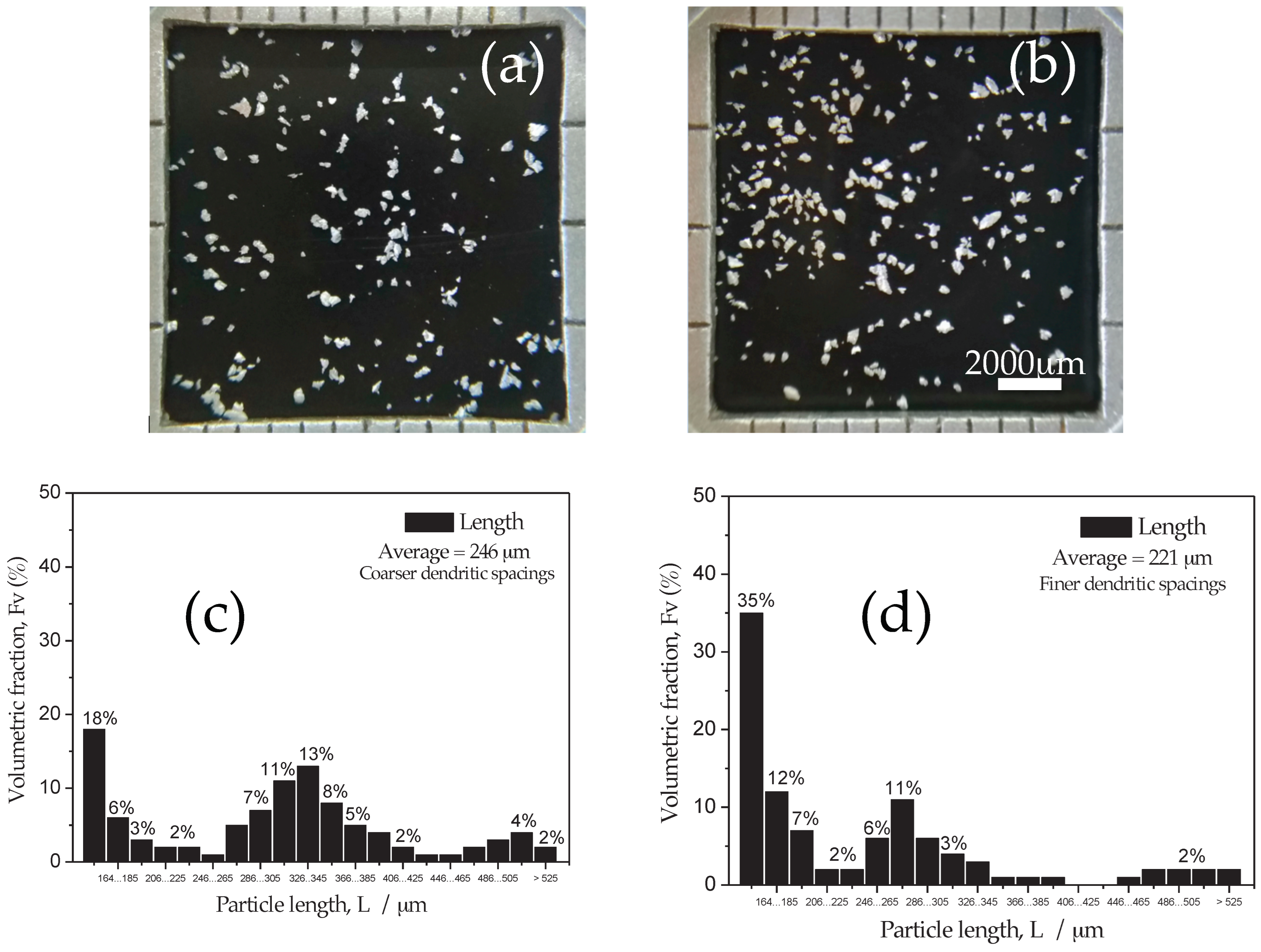
Figure 1 depicts the typical starting powder particles obtained from the as-cast Al-4 wt.% Cu alloy ingot. It is remarked that powders were obtained by using similar operational parameters, which provide similar averages of the particle lengths. Figure 1a shows the obtained powders from the as-cast ingot utilizing a cooling rate of 0.5 (±0.15) °C/s and coarser dendritic arm spacings resulted. When a cooling rate of 2.5 (±0.5) °C/s is applied, finer dendritic spacings are obtained. Evidently, the dendritic arms are not observed in these images, which will forwardly be demonstrated.
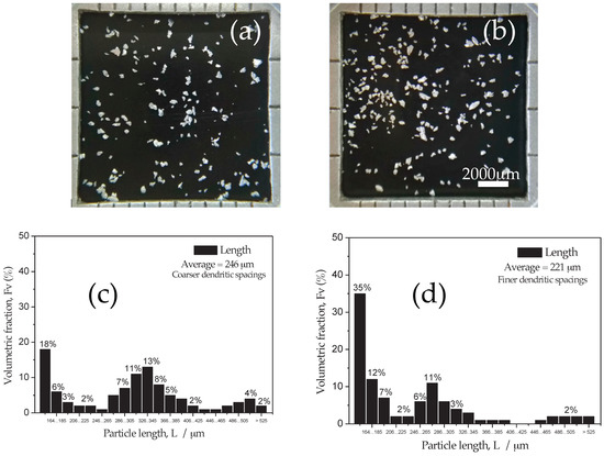
Figure 1.
Typical images obtained from the as-cast Al-4Cu alloy ingot: (a) using about ~0.5 °C/s cooling rate and (b) ~2.5 °C/s with their corresponding particle length distributions, and (c) attained coarser and (d) finer dendritic arm spacings.
However, it is revealed that the distributions of size particles displace to lower measured values than coarser ones, as depicted in Figure 1c,d. It is also remarked that the majority of particles exhibit a flaked-like morphology with a length of about 2× higher than the corresponding widths. It is also interestingly verified that the bimodal distributions are characterized, as also reported in other studies with Al powders obtained in similar operational conditions [25,26,27,28].
It is worth noting that the powder particles are obtained by drilling, as described in the experimental procedure. Due to this stage of processing, a certain “portion” of the Al-Cu alloy ingot is “withdrawn”. From the metallurgical point of view, since the powders are from as-cast conditions, it is expected that inside each powder particle, a determined microstructural array is preserved. Thus, each powder particle contains a few crystallographic grains. Inside each one of the grains, a microstructural array is constituted by dendritic spacings.
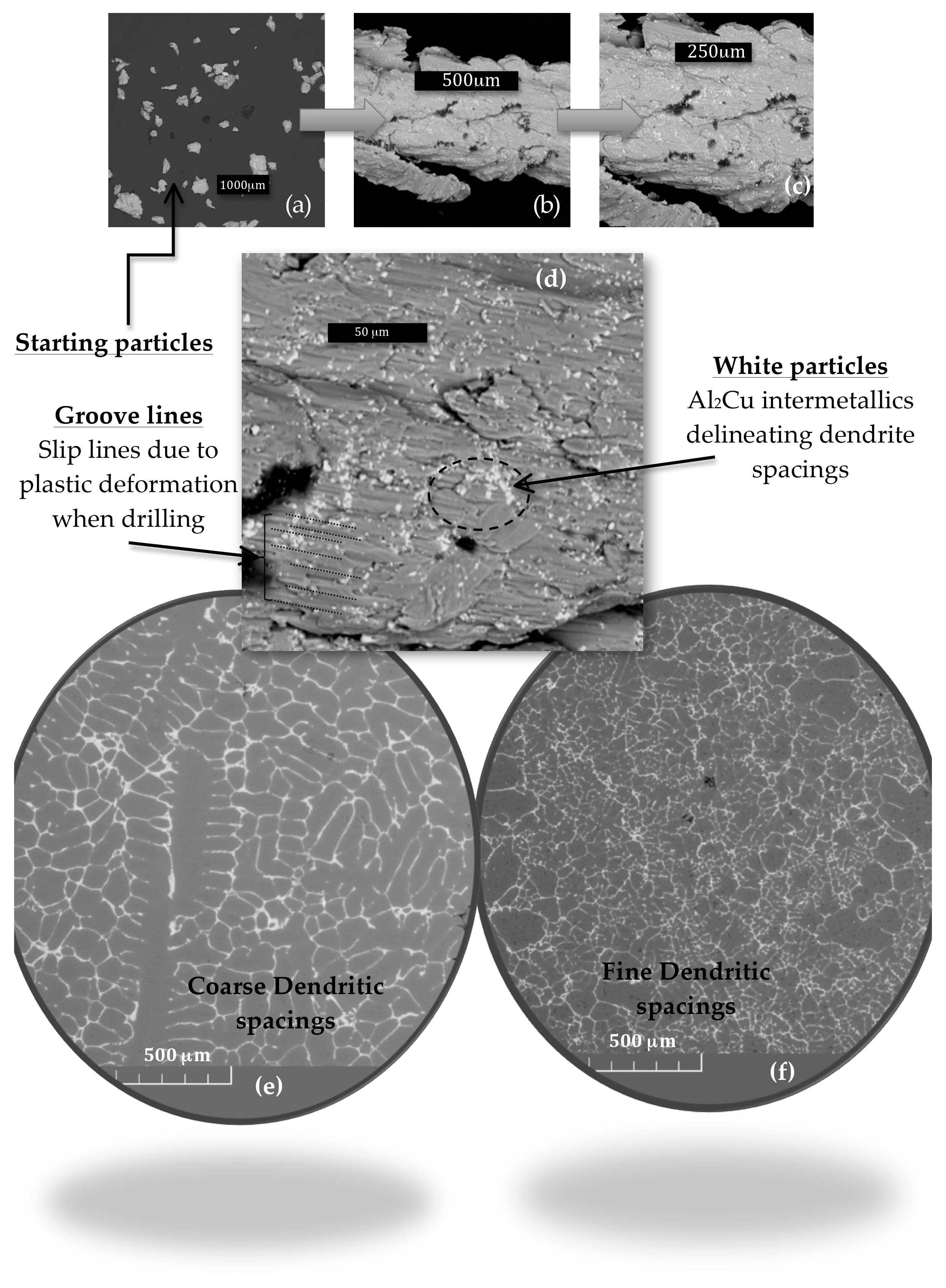
With this, intending to characterize these described microstructural parameters, a particular powder particle was examined. For this purpose, the magnifications were adopted. Figure 2a depicts the starting powder particles from the drilled as-cast Al-Cu alloys. Sequentially, three magnifications are applied in order to characterize the possible grain boundaries and its internal dendrite spacing arrays, as shown in Figure 2b–d. Based on the SEM typical images, it is not possible to affirm that the grain boundaries are clearly characterized. This seems to be associated with the fact that the drilling provokes the “slip” lines during the plastic deformation, as the groove and rough surface depicted in Figure 2d.
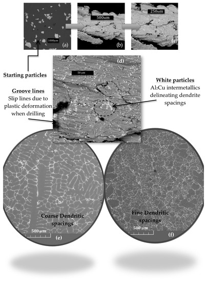
Figure 2.
Typical SEM images: (a) the starting drilled as-cast Al-Cu alloy powders; (b–d) distinct magnifications of powder revealing Al2Cu intermetallics (white/bright regions); the slip lines (plastic deformation) and the rough surface of the powder; and (e) showing the coarse and (f) the fine dendritic spacings characterized in the compacted samples (600 MPa).
However, it is clearly verified that the white-bright regions are characterized. These are surely corresponding with the resulting Al2Cu intermetallic particles. It is recognized from the metallurgical point of view that, these Al2Cu particles are allocated at interdendritic arms regions, as also shown in Figure 2d. It is speculated that the Al2Cu intermetallic is delineated as the secondary dendritic arm spacings (λ2) sizing of about 30 (±6) μm, due to the examined powder particles being from the as-cast Al-Cu alloy ingot, which is more rapidly cooled.
Figure 2e,f show the typical coarser and finer λ2 prevenient from the cooling rates of about 0.5 and 2.5 °C/s, respectively. Similar magnitudes of λ2 are reported in previously published articles concerning Al-Cu-based alloys in the as-cast condition [12,15,30,31,32,33,34]. It is remarked that these SEM images shown in Figure 2e,f are obtained and characterized when the compacted samples (under compaction pressure 600 MPa) are appropriately ground (SiC papers #1200 mesh) and examined by using a BSE (backscattered electrons) technique.
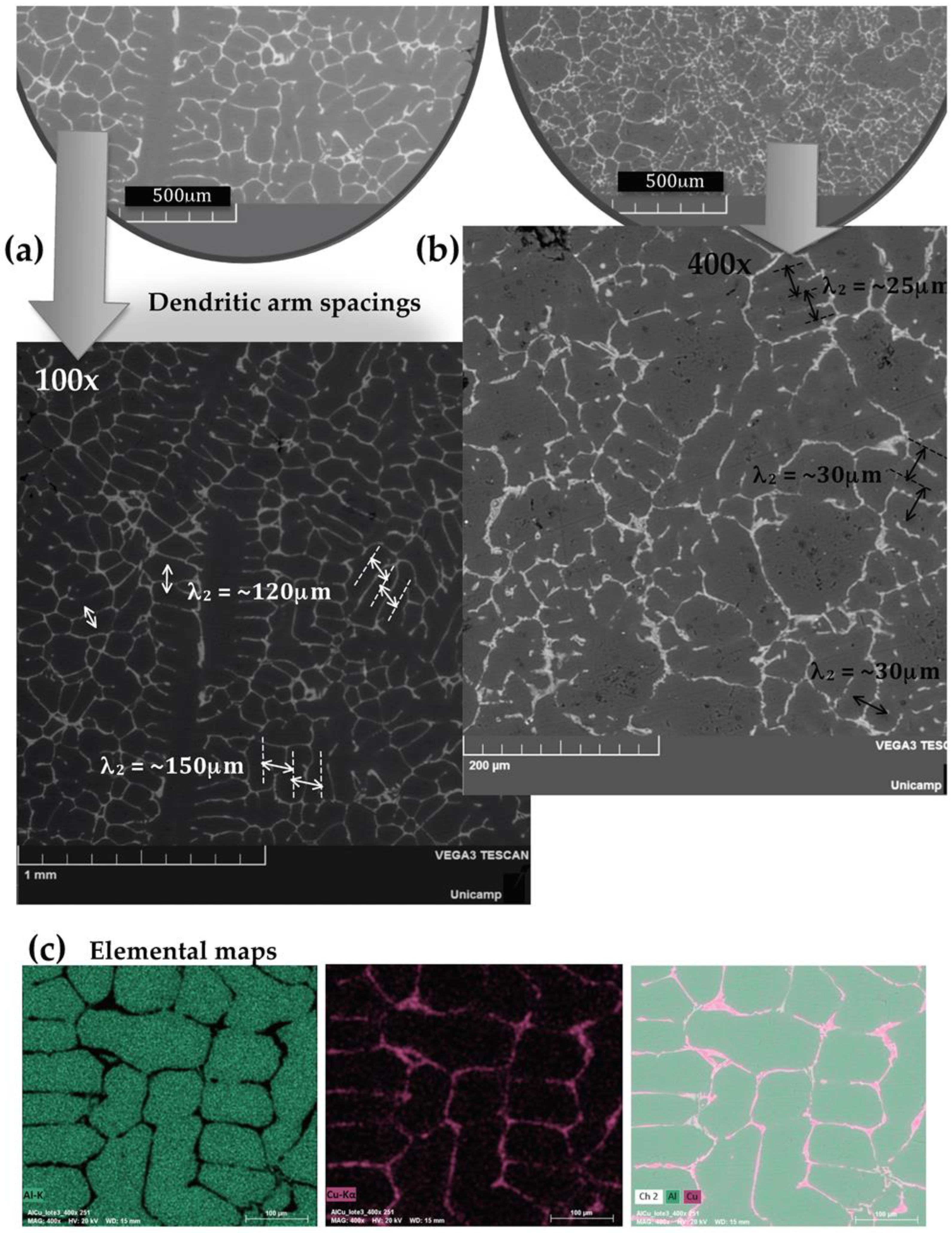
Figure 3a,b show the obtained SEM micrographs of the coarse and fine λ2 at magnifications of 100× and 400×. This evidences that a coarser λ2 is about 150 μm, while a fine λ2 characterizes its arm spacings approximately 4 or 5 times (~30 μm) lower than the coarse sample. This is intimately associated with the two distinct cooling rates applied when the multi-directional unsteady-state solidification is conducted. It is important to remark that the applied cooling rate has a very important role in the resulting properties. For instance, a high cooling rate (higher than 5 °C/s) is commonly reached when the water-cooled permanent-steel mold is involved.
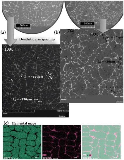
Figure 3.
(a) Typical SEM/BSE images characterizing both the feature of (a) the coarse and (b) the fine dendritic arm spacings (λ2) sizing of about 150 μm and ~30 μm, respectively; and (c) the elemental maps showing the Al-matrix and Cu-rich regions (including Al2Cu phase).
Figure 3c depicts the resulting Al- and Cu-Kα and the conjugated SEM images constituting the elemental maps are also shown. These indicate the Al-rich and Cu-rich (Al2Cu intermetallics) regions. It is remembered that the solubility limit of Cu in the Al matrix is ~5.6% [14,15], which justifies some few “red” points distributed throughout the Al matrix. The Al2Cu intermetallics are majority located at the interdendritic regions. However, it is possible that other Al2Cu phases (e.g., θ, θ′ and θ″) be also located inside or diluted into the Al matrix, as previously reported [35,36,37,38]. These other morphologies, cubic particles, needle-like and nano-scaled needle-shaped particles (lower than 5 μm) correspond to θ, θ′ and θ″, respectively [38]. These Al2Cu are commonly characterized using TEM techniques. The θ-Al2Cu phase interfacing with the α-Al constitutes the eutectic network. With magnifications of 100× up to 2000× using both optical and SEM techniques, these phases are more easily characterized.
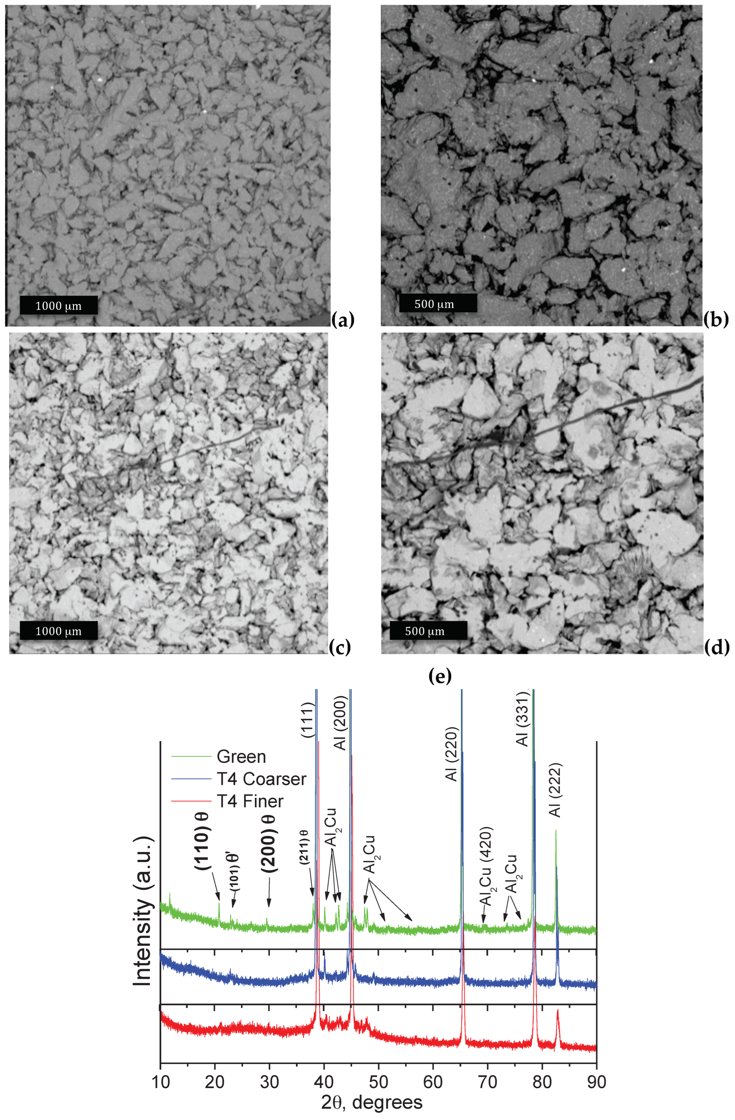
Figure 4a,b characterize the typical SEM/BSE images corresponding with the two different magnifications (50× and 100×) of the samples transversally compacted (T4 treated), which are entitled as the transverse samples, as previously mentioned. Figure 4c,d demonstrate also the two distinct magnifications (50× and 100×) for the longitudinally compacted samples (designated as longitudinal samples).
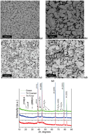
Figure 4.
(a) Typical SEM/BSE images depicting morphologies of: (a,b) the sample transversally compacted, (c,d) the sample longitudinally compacted at 600 MPa; and (e) the resulting XRD patterns corresponding with the green sample, T4-treated with the coarse and the fine dendritic spacings with its corresponding detected Al2Cu phases (JCPDS # 01-1180).
When the SEM images shown in Figure 4 are compared, it is observed that a slight tendency to more flattened morphology favors the transverse sample; and a morphology more spheroidal characterizing the longitudinal sample is constituted. It is worth noting that the initial powder particles (flaked-like morphology, shown in Figure 1) are identical for both the transverse and longitudinal samples. This induces that the distinctive compaction directions provide slight differences in the compacted particle morphologies. It was previously reported that both the transverse and longitudinal samples have also very similar compressibility capacities [24]. This suggests that the deformation capacity is identical under the same compaction pressure. This is attributed to the nature of the initial powder utilized (i.e., magnitudes of the particle sizes, chemical composition and morphology).
After comparing these compacted morphologies, the resulting XRD patterns are also analyzed, as shown in Figure 4e. The two T4 treated samples are compared with a typical green sample (not sintered or treated), which was only compacted. Based on this comparison, it is evidenced that both the T4-treated coarse and fine samples have decreased those intensity peaks correlated with the θ-Al2Cu, mainly those corresponding with crystallography planes (110) and (200) at ~21 and 29 degrees, respectively. Other peaks corresponding with the θ-Al2Cu phase are also decreased, but no substantial peaks are occurred with (110) and (200) planes. This suggests that the main θ Al2Cu phases have partially dissolved into the Al matrix, which seems to be constituted a supersaturated solution. Forwardly, this observation will help to explain the reason that the mechanical results are improved. Zhang et al. [37] have also previously reported similar results.
Since comparing the induced Al2Cu phases after the T4 treatment and the resulting morphologies were attained, it should be verified the resulting mechanical behavior reached in each one of the different dendritic spacings and analyzed their correlation with the mechanical responses. In this sense, in the next section both the tensile and compressive strengths are discussed.
3.2. Anisotropic Tensile and Compressive Strengths
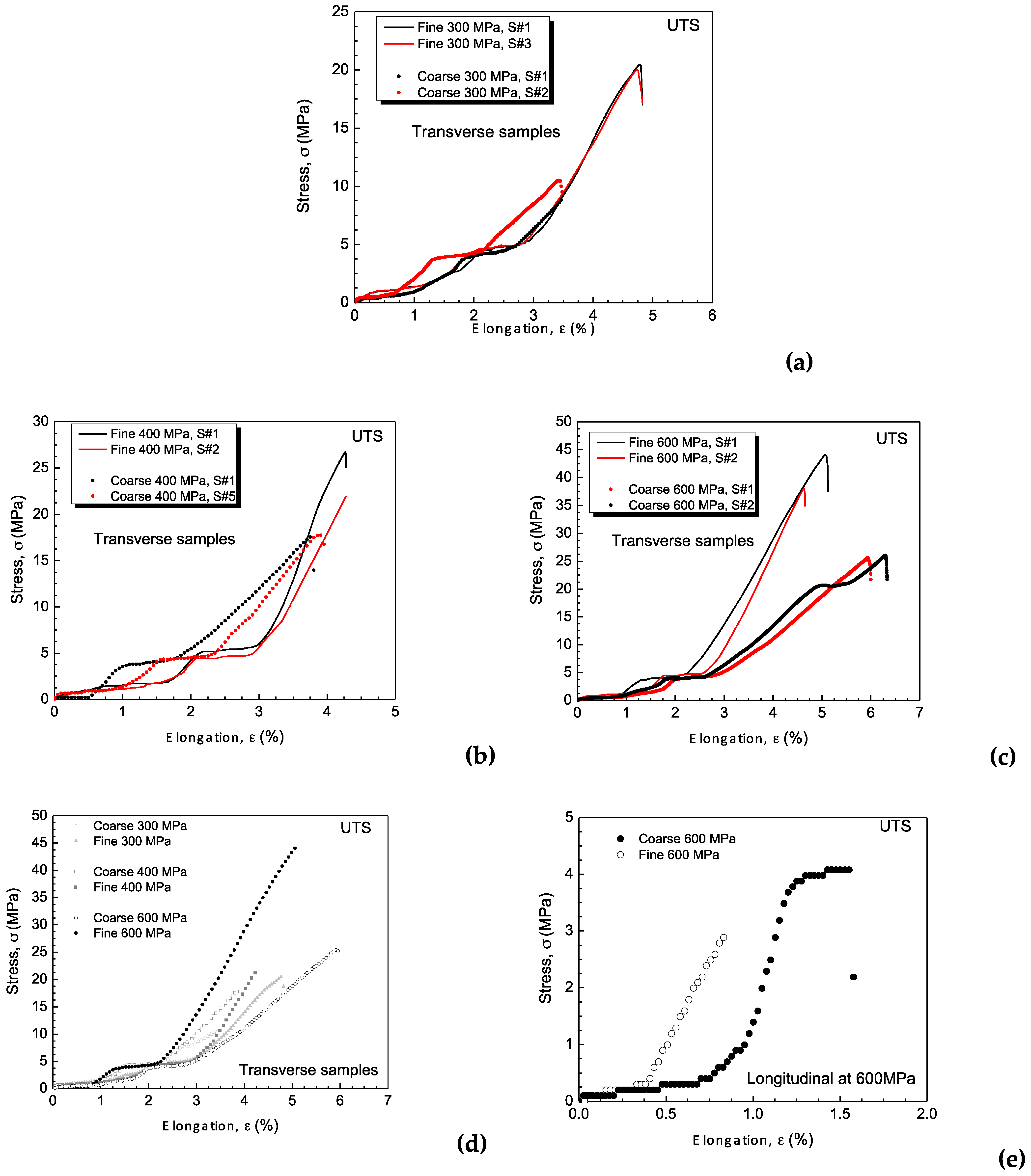
Figure 5 demonstrates the experimental results of the tensile strengths of both the transverse and longitudinal samples. Duplicate results are depicted in each one of the plotted graphs. Figure 5a–c show the tensile strength results of the transverse samples using the three distinct compaction pressures, i.e., 300, 400 and 600 MPa. It is clearly observed that with the increase in the compaction pressure, the UTS results of both the fine and the coarse samples are also increased. These results are summarized in Table 1 in order to facilitate the comparisons among the examined samples. A comparison among all examined transverse samples is depicted in Figure 5d. Since all examined longitudinal samples have demonstrated similar (or equal) tendencies, typical stress vs. strain curves utilizing the fine and coarse dendritic spacings as initial powders are shown in Figure 5e. This occurrence seems to be associated with the compaction method, which provides a neutral line located approximately at the same line or fracture plane, i.e., perpendicular to the tensile direction. It is remarked that these samples are bi-directionally compacted, but the neutral line is not prevented. Based on this, the tensile strengths of these longitudinal samples will be considered as those results obtained from the diametric compression, as also previously reported [24].
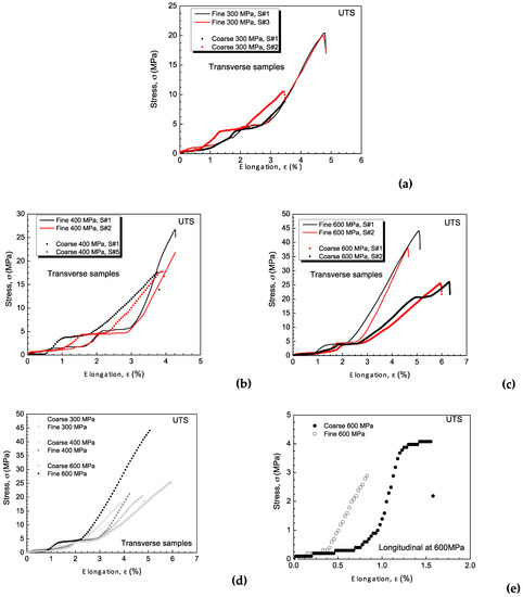
Figure 5.
The experimental results of the tensile strengths (stress vs. strain) of the Al-4Cu composite samples using the coarse and fine dendritic spacings as initial powders, and the compacted at the transverse direction using: (a) 300 MPa, (b) 400 MPa and (c) 600 MPa, (d) comparison among all transverse samples, and (e) typical results using 600 MPa in longitudinal direction.

Table 1.
Summarized values of the UTS (ultimate tensile strength) and elongation (ε) obtained from the stress vs. strain curves of the Al-Cu alloy samples utilizing two distinct dendritic arm spacings (λ2) inside the initial powders. The samples are compacted in both the transverse and longitudinal compaction directions.
Table 1 summarizes the ultimate tensile strengths (UTS) and elongations (ε) of all the examined transverse and longitudinal samples. It is evidenced that when the initial powders containing finer dendritic arm spacings are observed, the UTS results are higher than those samples containing coarser spacings, i.e., ~1.5× utilizing compaction pressure of 300 and 400 MPa, and about 1.7× when 600 MPa is used. Comparing the UTS among the coarse spacings samples and among the fine spacings, an increase of about 1.5× in the compaction pressures is reached. An increase of about 1.5× is also reached, as also observed in a previous investigation [24]. As aforementioned, all longitudinal samples have reached the same order of magnitude of both the UTS and ε. This is intimately associated with the neutral line provoked when the longitudinal samples are compacted.
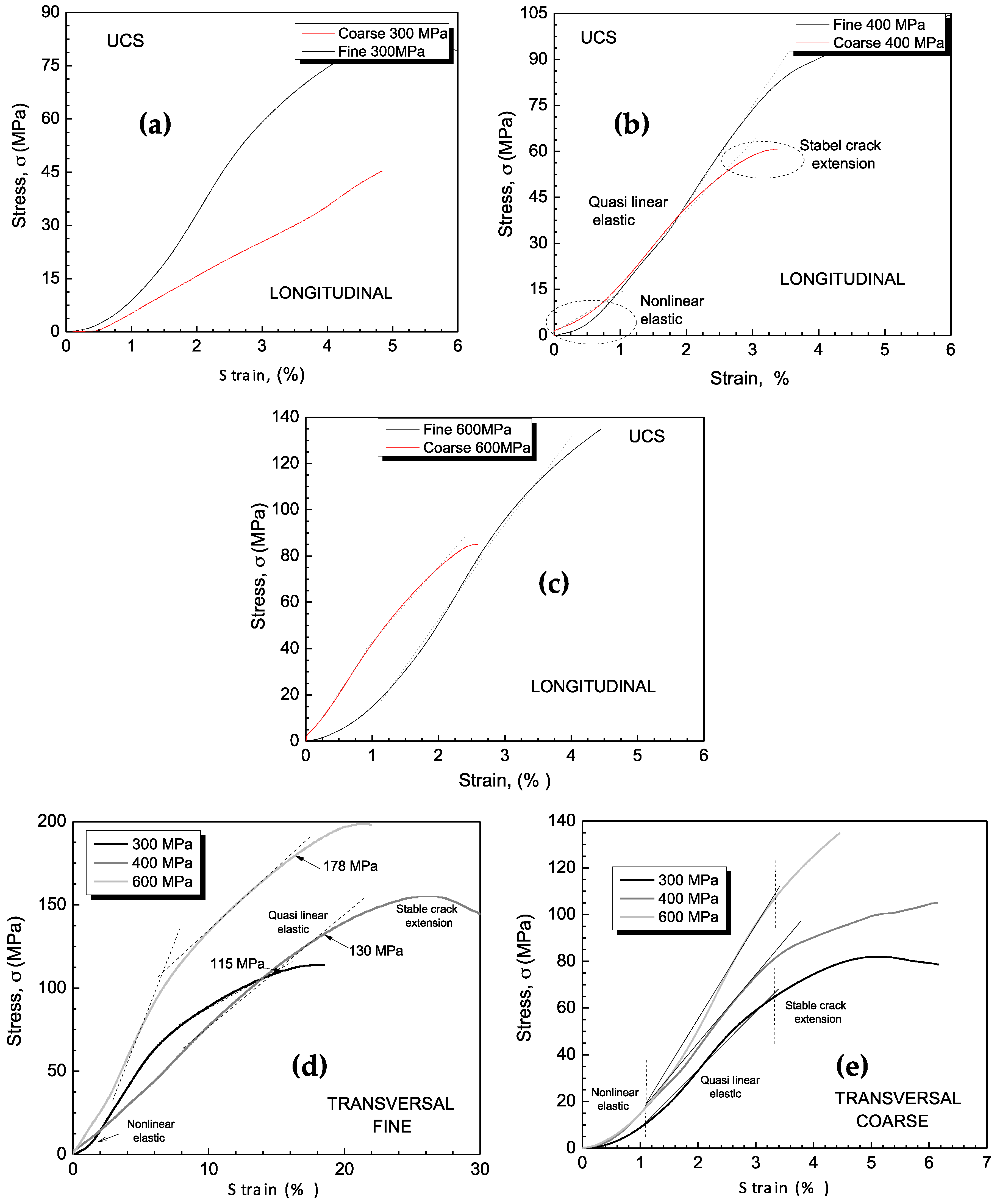
Figure 6a–c depict the experimental results of the compressive tests in the longitudinal directions utilizing the fine and coarse dendritic arm spacings and under the three distinct compaction pressures. Figure 6d,e show the results of compressive strengths corresponding with the samples utilizing both the fine and coarse spacings and adopting the three compaction pressures considering the transversally compacted samples, respectively.
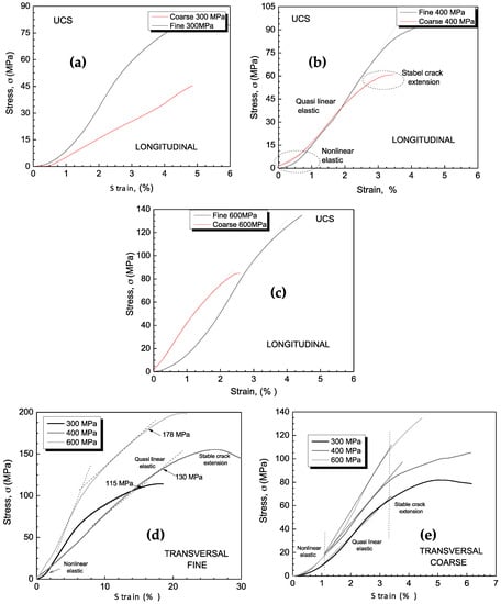
Figure 6.
Experimental results of the compressive strengths (stress vs. strain) of the samples utilizing coarse and fine spacings compacted in the longitudinal direction: (a) at 300 MPa, (b) 400 MPa and (c) 600 MPa. The transverse samples under the three compactions with: (d) finer and (e) coarser arm spacings.
As also observed in the tensile strength results, the ultimate compressive strength (UCS) increases with the increase in the compaction pressure (about 1.3×). Similar results are observed when the T4 and the sintered samples are compared [24]. Additionally, the samples with finer dendritic arm spacings have shown their corresponding UCS values at least 1.9× higher than the coarser ones. When the longitudinal samples are compared, also those samples produced using powders with finer arm spacings provide the UCS higher (~1.6×) than the coarser ones. It is remarked that the stress vs. strain for all examined samples has similarly shaped curves with the three distinct regions. The first region is designated as the nonlinear elastic region, the quasi-linear elastic and the last region characterizing the stable crack extension, as also previously reported [38].
Table 2 shows the UTS values, elongations and diametrical compression (DC) based on Hertz’s equation, as previously reported [23,24,38,39]. The determined DC values are used in order to calculate the anisotropy ratio (AR) or the anisotropy degree. Although the DC corresponds with the indirect tensile strength and commonly is determined for composites and ceramic composites, it was previously reported [24] that the DC represents perfectly the tensile strength of the Al-Cu powders as sintered and T4 treated samples. Based on this, the DC results are used to determine the anisotropy ratio (AR). This is because the UTS results determined in the longitudinal samples have not evidenced tendencies or behavior. This occurrence is associated with the neutral line (or plane) formation when the bidirectional compaction is carried out, as previously mentioned.

Table 2.
Experimental UCS (ultimate compressive strength), elongation (ε), diametrical compression (DC) and anisotropic ratio (AR) considering both the finer and coarser dendritic arm spacings inside the initial powders utilized to produce the Al-Cu alloy composites.
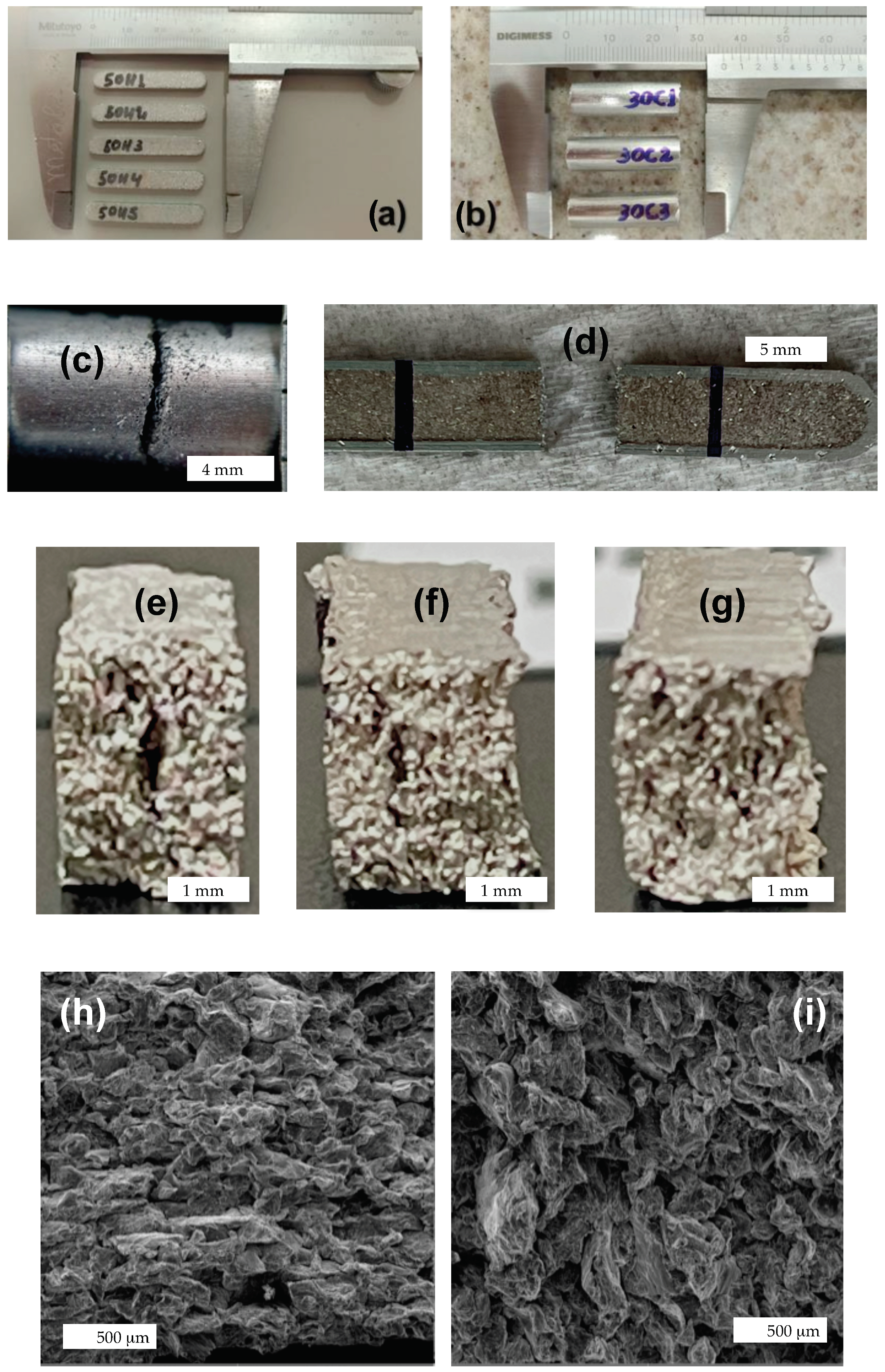
Figure 7a,d show the specimens of the Al-Cu composites designated as the transverse and longitudinal samples. Figure 7c depicts the longitudinal (cylindrical) sample after the tensile test, which has induced tension in the same direction as the compaction direction. Figure 7d shows a transverse sample (flat specimen) after the tensile test, which was carried out in a perpendicular direction in relation to the compaction direction. The fracture plane in the cylindrical specimen (longitudinal sample) is perpendicular to both the compaction and tensile testing directions. On the other hand, the flat specimen (transverse sample) has its fracture plane perpendicular to the tensile test, but parallel to the compaction direction. Figure 7e–g depict the three flat specimens subjected to the compression tests, which are perpendicular to the compaction direction. It is clearly observed that distinct cracks are produced. Figure 7e is a post-mortem transversal compression (using powder with finer arm spacings) carried out in a transverse sample compacted using a pressure of 300 MPa. It is observed that a crack is displayed in the central region of the specimen and extended in the same direction as the compressive load (vertical). Figure 7f,g are similar samples, which were compacted using 400 and 600 MPa, respectively. It is clearly observed that the cracks extend differently from that which occurred in Figure 7e, and the crack damage is more pronounced. Figure 7g shows smaller cracks than other examined samples and more homogeneously distributed to the bulk of the specimen.
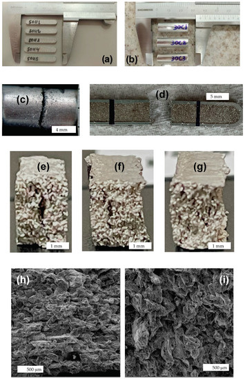
Figure 7.
The compacted and sintered samples: (a) flat (transverse) and (b) the cylindrical (longitudinal) samples, (c) typical fracture in the cylindrical sample, (d) typical fracture in the transverse sample; the resulting crack aspects in the sample compacted at (e) 300 MPa, (f) 400 MPa, and (g) 600 MPa, evidencing distinct crack distributions; and (h,i) are the SEM images (magnification 100×) showing the fracture surface of a flat (transverse) and the cylindrical (longitudinal samples, respectively.
Figure 7h,i show the typical fractographic images after the tensile tests of the flat and cylindrical specimens, respectively. It is reasonably perceived that the flat (transverse) sample is more consolidated in terms of the coalescence of particles and bonding than the longitudinal sample. It is recognized that the intergranular fracture has a smooth surface without dimples formation and cleavage facets are characterized. This is a feature associated with low plastic deformation provoking a brittle fracture [39,40]. Distinct fracture mechanisms considering distinct size-reinforced matrix and Al-based composites are reported [41,42,43,44].
It is reported that the particle size, spatial distribution and nature (brittle or ductile) of particles (initial powders) have important roles in the fracture mechanism and, consequently, in the resulting mechanical behavior. Yang et al. [41] have recently reported that in an A356 alloy containing a dendritic formation as a microstructural characteristic, the sample with the fine dendrites has crack propagation occurring predominantly in a trans-dendrite path (~62% of the total length of cracks in fracture section). On the other hand, when a coarser microstructure array is examined, the fracture mechanism favors the cracks occurring along the eutectic regions [41].
Although any correlation with the fracture aspect and/or with the fracture mechanisms (evidencing trans-dendritic or transgranular cracking propagation) is clearly confirmed, it seems that the transverse sample has a less “porous” or less rough surface than the cylindrical (longitudinal) sample. It can be said that a mixture of brittle and ductile fractures domains the resulting mechanism for all examined samples. The longitudinal sample seems to be slightly more ductile than the transverse samples, which can be confirmed with those UTS and elongation shown in Table 2. Furthermore, it is presumed that the transverse sample exhibits a stronger bridging effect, leading to an increase in bonding energy at the interface between elongated/deformed particles. This observation aligns with previous reports by Galen and Zavaliangos [18].
3.3. Anisotropic Ratios
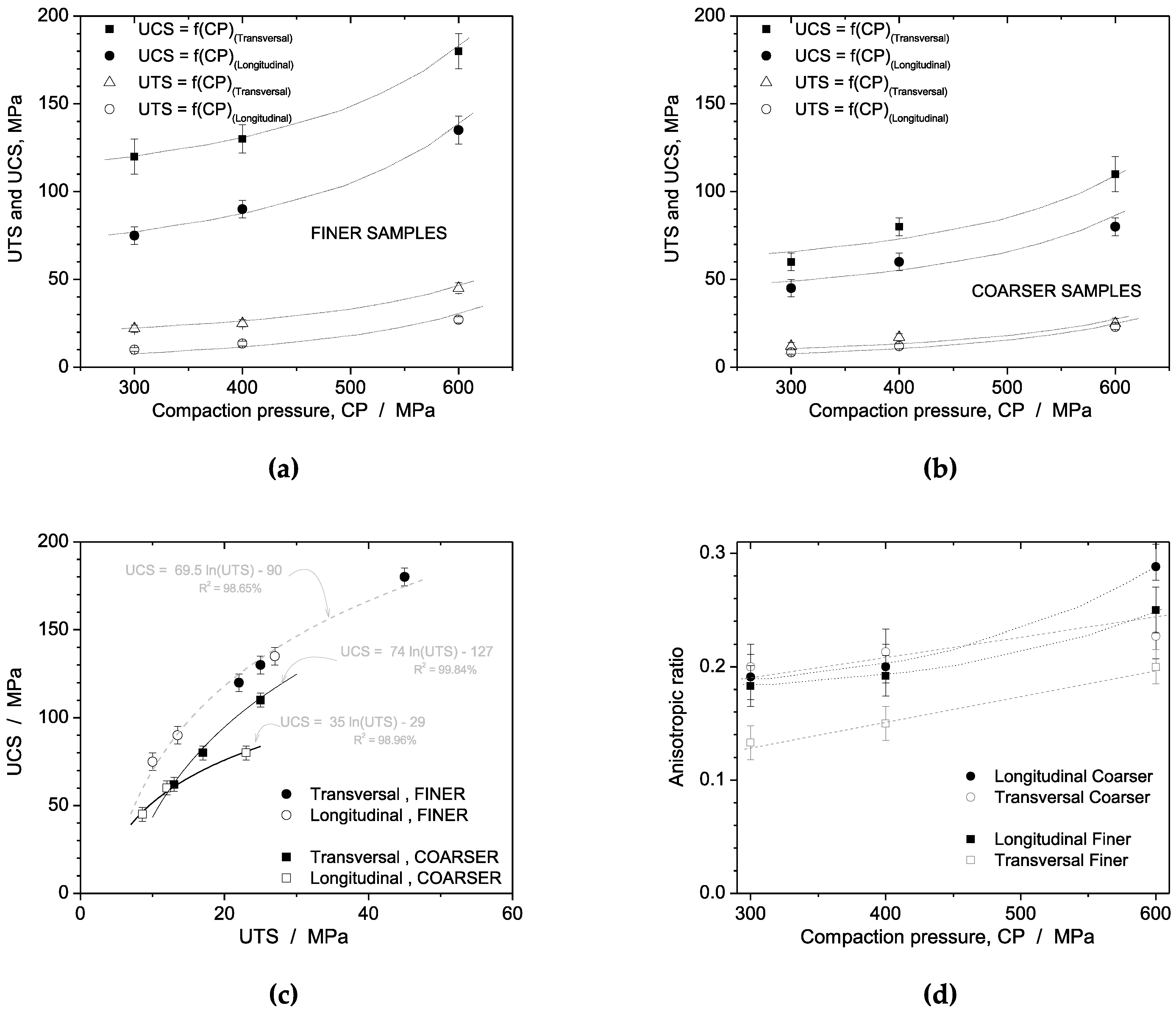
Figure 8a,b summarizes the UCS (ultimate compressive strength) and the UTS (ultimate tensile strength) as a function of the compaction pressures considering both the coarser and finer dendritic spacings. It is evidenced that both the compaction direction and refinement of the dendrite spacings affect significantly the resulting mechanical responses. The highest UTS and UCS are attained when the transverse and finer arm spacings are considered.
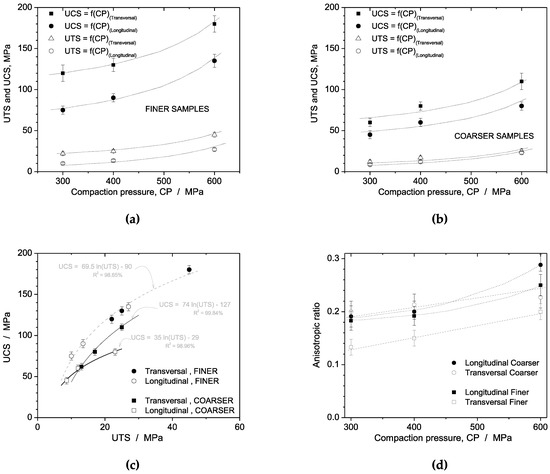
Figure 8.
The experimental results of the UTS and UCS vs. the compaction pressure (CP) considering: (a) finer and (b) coarser dendritic arm spacings; (c) correlation between the UCS and UTS; and (d) the anisotropic ratio between the UCS and UTS for the longitudinal and transverse samples considering both the coarse and fine dendrite arm spacings.
A correlation between the UCS and UTS is shown in Figure 8c. As also previously reported [24], a nonlinear trend is characterized. A unique logarithmic equation (i.e., UCS = 69 ln(UTS) − 90) describes the trends for both the transverse and longitudinal samples, but when the powder with finer dendritic arm spacings is utilized. Interestingly, this trend equation is very similar to that obtained when the transverse and longitudinal samples for the sintered Al-Cu alloy samples were investigated, i.e., 64 ln(UTS) − 80. On the other hand, when the sample utilizes powders with coarse dendritic spacings, the tendency for the longitudinal sample is different from the transverse sample. The ratio between the UCS and UTS of the transverse sample is higher than the ratio of the longitudinal samples, as depicted in Figure 8c.
The strength anisotropy or anisotropic ratio is determined by determining the ratio between the UCS and UTS considering the transverse and longitudinal samples associated with the coarse or fine dendritic arm spacings to produce the samples. Galen and Zavaliangos [18] have stated that the anisotropy ratio for deformable materials is lower than 1 and becomes smaller with increasing densification.
Figure 8d shows the strength anisotropy ratio (AR) as a function of the compaction pressure. It is verified that all examined samples have an AR lower than 1. This suggests that these examined samples exhibit ductile behavior, as reported by Galen and Zavaliangos [18]. However, a ductile material commonly demonstrates its degree of anisotropy decreasing with the increase in densification, i.e., with the increase in the compaction pressure. Based on the attained AR results, all examined samples show increasing trends with the increase in the compaction pressure. This suggests that the examined samples become more isotropic with the increase in the compaction pressure.
This means that independent of the compaction direction, i.e., longitudinal or transversal, there exists a trend to become more isotropic with the increase in the compaction pressure. It is important to remark that this tendency is not permanently observed when the ductile materials are compacted, as in the case of the Al-Cu alloy powders utilized in a previous investigation [24]. In this mentioned study [24], the transverse samples have demonstrated the anisotropic ratios quasi-linearly increased trends, while the longitudinal samples showed nonlinear decreasing trends. This was verified independently of only a sintering treatment being applied or if the T4 is carried out. Additionally, the effects of the heat treatments have also revealed that the sintered longitudinal samples are more isotropic or less anisotropic than the T4-treated longitudinal samples.
Galen and Zavaliangos [18] have reported that the same material with non-equiaxed morphology (acicular) has higher strength anisotropy than the same material with equiaxed morphology. In a previous investigation [24], a similar trend is also reported. It is found that the morphology, the compaction pressure and the heat treatments are important parameters affecting the anisotropic strength.
In addition to these studies, and based on the foreshown results, it is found that the microstructural arrays constituting the initial powders (i.e., distinct dendrite arm spacings) have also important roles in the anisotropic ratio. It is recognized that there is a limitation in this present investigation due to, up to the present moment and considering the analyzed results, it is not possible to determine or to state if the dendritic spacings are more influent than other parameters, or if there exists a conjugated or associated effect among them. Although a very similar tendency of the correlation between the UCS and UTS is verified when compared with a previous study [24], i.e., 69.5 ln(UTS) − 90 and 64 ln(UTS) − 80, respectively, the correlation AR vs. compaction pressure demonstrates that both the AR trends of the longitudinal and transverse samples are increased. Also, transverse and longitudinal samples exhibit nonlinear and linear trends, but in this investigation, all AR trends are increased trends and the previous one has opposite trends. Another interesting observation that is different from the previous study is the fact that, for example, at 300 and 400 MPa, except for the transverse sample with finer arm spacings, all examined samples have shown AR values in the same order of magnitude.
When at 600 MPa the AR is analyzed, slight differences are observed, as can be seen in Figure 8d. The longitudinal samples (with coarse and finer arm spacings) have an AR between ~0.24 and 0.30, while those corresponding with the transverse samples (coarser and finer) are slightly lower (between 0.18 and 0.22) than the longitudinal ones. Interestingly, when observing the AR values at 600 MPa in a previous study [24], the AR for all examined samples are similar (~0.14), except for the T4 samples with the AR, which is 0.08.
At 600 MPa the anisotropy ratios demonstrate a decreasing sequence with the highest ratio being that of the longitudinal coarser spacing sample followed by the longitudinal finer spacing sample and the transverse samples with the coarse and fine arm spacings at the last two positions, and the lowest value is that of the transverse finer spacing sample. This evidences that the transverse samples, when compacted at 600 MPa have higher differences between the UCS and UTS values, and the finer dendrite arm spacings contribute to increasing the mentioned difference. Although there are differences in the UTS and UCS values depending on the microstructural refinement, the same order of magnitude in the UCS is attained. For example, the longitudinal finer spacings sample has a UCS reaching of about 90 MPa and the transverse coarser spacings sample reaches of about 80 MPa. Considering the error ranges, equal ranges of values are attained. This shows that depending on the compaction level intended, planning in the compaction direction should be preprogrammed, or vice versa. Also, when a restriction or limitation in the compaction direction and pressure (e.g., 400 MPa) is prevalent in a certain project or component, it can also be programmed or planned if a powder is obtained from the ingots or from the recycled alloys which possess a more refined microstructural array.
With this, it seems that the dendrite arm spacing confirms its effect on the AR of Al-Cu alloys produced using powders constituted by the distinct sizes of the dendrite spacings. Associating with this very recognized metallurgical effect to the compaction direction, the highest mechanical behavior is that of the sample produced with finer spacings and applying compaction in the transversal direction. Considering the effects of the dendritic arm spacings on the anisotropy strength, it can be stated that the largest anisotropy ratio is that of the sample with finer dendrite arm spacing, which has its transverse strength of about 1.5 times higher than the longitudinal strength (considering both UTS and UCS results). A similar observation is perceived when Galen and Zavaliangos [12] investigated the anisotropy strength in the steel powders and associated it with the resulting morphology powders, not correlating with the microstructural refinement. Additionally, the finer arm spacings associated with the compaction were carried out in the transversal direction, and the highest anisotropy ratio is constituted.
4. Conclusions
Based on the attained results of mechanical behavior using two distinct powders containing different dendrite arm spacings (coarse and fine) of the as-cast Al-Cu alloy, the following conclusions can be drawn:
- It is found that, although distinct microstructural arrays (i.e., dendrite spacings) are obtained as a function of the cooling rates applied, very similar morphologies of the drilled powders are attained. Also, all crystallographic phases identified are very similar for all examined samples. After the compaction and sintering, the identified phases are identical to those in the as-cast condition.
- It is also found that the increase in the compaction pressures of both the UCS (ultimate compressive strength) and UTS (ultimate tensile strength) is also increased. When analyzing the sample compacted at transversal and longitudinal directions, it is evidenced that the UCS and UTS values corresponding with the transverse samples are higher (~1.5×) than the longitudinal samples. When the powders utilized to produce the specimens are separated between finer (~30 μm) and coarser (~150 μm) dendritic spacings, it is revealed that the fine dendritic spacing provides a higher UCS and UTS in both the transverse and longitudinal samples. This induces that the dendritic spacings have also important roles to determine the anisotropic strengths of the samples examined.
- The anisotropic ratio (AR) is determined using the UTS/UCS ratio. Based on the attained AR results, it is found that all examined samples have shown increasing tendencies with the increase in the compaction pressure. This induces that independent of the compaction directions, i.e., longitudinal or transversal, a tendency to become more isotropic with the increase in the compaction pressure is characterized.
- When the UCS per UTS ratios are analyzed, a unique mathematic relation describes this trend ratio (i.e., 69.5 ln(UTS) − 90) involving both the transverse and longitudinal samples. However, it is interestingly observed that when only the samples containing the fine dendrite arm spacings are considered. When the longitudinal and transverse samples with coarser dendritic spacings are examined, the UCS/UTS ratios characterize two distinctive equations to describe the tendencies, which are different from those determined by the samples with finer spacings.
- Considering the anisotropy ratios, independently of coarser or finer arm spacings are considered, the transverse samples have depicted linear increasing trends. On the other hand, in the longitudinal samples considering both coarser and finer arm spacings, nonlinear increasing trends are clearly established. Although it is not possible to determine how much the dendritic spacing overlaps or overestimates the effects of the compaction directions (transverse or longitudinal), the compaction loading and the powder morphology, it is evidenced that they have important roles in the anisotropic strengths. It seems that the effect is combined or conjugated with the compaction direction, which affects significantly the tensile and compressive anisotropic strengths.
- It is also found that at 300 and 400 MPa, excepting the transverse sample with finer arm spacings, all examined samples have the same order of magnitude for the anisotropy degree. Interestingly, at 600 MPa, the anisotropy ratios depict a decreasing sequence: the highest ratio is that of the longitudinal coarser spacing sample, followed by the longitudinal finer spacing sample and the transverse samples with coarser and finer arm spacings. Although there are differences in the UTS and UCS values depending on the microstructural refinement, the same order of magnitude in the UCS is prescribed. Depending on the compaction level intended, planning in the compaction direction can be preprogrammed or vice versa. Based on the fact that the recycled powder particles from the conventional machining, drilling and turning can be considered. With this, environmentally friendly aspects are attained and hazardous stages are also substantially decreased or eliminated.
Author Contributions
R.S.B. and J.F.Q.R. prepared alloy samples and also contributed to discussion and writing texts/discussion. R.S.B., R.F.G.B. and L.C.P. carried out mechanical behavior measurements, organized the data and also provided correlations. A.D.B. and J.F.Q.R. carried out the XRD measurements and organized and treated the data attained. A.D.B. also helped with the general organization and with the English in the written manuscript. W.R.O., R.S.B., L.C.P. and A.D.B. contributed to the general organization of the experimentations, analyses and correlations. W.R.O. and A.D.B. wrote and organized. All authors have read and agreed to the published version of the manuscript.
Funding
The financial support provided by FAEPEX-UNICAMP (#2252/23), CAPES (Coordination for the Improvement of Higher Education Personnel), the Ministry of Education, Brazil, Grant number 1) and CNPq (The Brazilian Research Council) Grants, 407595/2022-8; 313272/2021-2; and 310010/2020-9.
Institutional Review Board Statement
Not applicable.
Informed Consent Statement
Not applicable.
Data Availability Statement
The authors also declare that all research data supporting this publication are directly available within this publication.
Acknowledgments
The authors acknowledge the work of Luiz A. Garcia (technician department), who contributed to technical activities and equipment organization.
Conflicts of Interest
The authors declare no conflict of interest.
References
- Bulei, C.; Stojanovic, B.; Utu, D. Developments of discontinuously reinforced aluminium matrix composites: Solving the needs for the matrix. J. Phys. Conf. Ser. 2022, 2212, 012029. [Google Scholar] [CrossRef]
- Soo, V.K.; Peeters, J.; Paraskevas, D.; Compston, P.; Doolan, M.; Duflou, J.R. Sustainable aluminium recycling of end–of–life products: A joining techniques perspective. J. Clean. Prod. 2018, 178, 119–132. [Google Scholar] [CrossRef]
- Rombach, G. Raw material supply by aluminium recycling–Efficiency evaluation and long–term availability. Acta Mater. 2013, 61, 1012–1020. [Google Scholar] [CrossRef]
- Olivieri, G.; Romani, A.; Neri, P. Environmental and economic analysis of aluminium recycling through life cycle assessment. Int. J. Sustain. Dev. World Ecol. 2006, 13, 269–276. [Google Scholar] [CrossRef]
- Thomas, M.P.; Wirtz, A.H. The ecological demand and practice for recycling of aluminium. Resour. Conserv. Recycl. 1994, 10, 193–204. [Google Scholar] [CrossRef]
- Reis, D.A.P.; Couto, A.A.; Domingues, N.I., Jr.; Hirschmann, A.C.O.; Zepka, S.; Moura, N.C. Effect of artificial aging on the mechanical properties of an aerospace aluminum alloy 2024. Defect Diffus. Forum 2012, 326–328, 193–198. [Google Scholar]
- Reddy, T.B.; Karthik, P.; Krishna, G. Mechanical behavior of Al-Cu binary alloy system/Cu particulates reinforced metal-metal composites. Results Eng. 2019, 4, 100046. [Google Scholar] [CrossRef]
- Iswanto, P.T.; Pambekti, A. Heat treatment T4 and T6 effects on mechanical properties in Al-Cu alloy after remelt with different pouring temperatures. Metalurgija 2020, 59, 171–174. [Google Scholar]
- Alexopoulos, N.D.; Velonaki, Z.; Stergiou, C.I.; Kour-koulis, S.K. Effect of ageing on precipitation kinetics, tensile and work hardening behavior of Al-Cu-Mg (2024) alloy. Mater. Sci. Eng. A 2017, 700, 457–467. [Google Scholar] [CrossRef]
- Fernandez Gutiérrez, R.; Sket, F.; Maire, E.; Wilde, F.; Boller, E.; Requena, G. Effect of solution heat treatment on microstructure and damage accumulation in cast Al-Cu alloys. J. Alloys Compd. 2017, 697, 341–352. [Google Scholar] [CrossRef]
- Rivera-Cerezo, H.; Gaona-Tiburcio, C.; Cabral-Miramontes, J.; Bautista-Margulis, R.; Nieves-Mendoza, D.; Maldonado-Bandal, E.; Estupiñan_lopez, F.; Almeraya-Calderón, F. Effect of heat treatment on the electrochemical behavior of AA2055 and AA2024 alloys for aeronautical applications. Metals 2023, 13, 429. [Google Scholar] [CrossRef]
- Quaresma, J.M.V.; Santos, C.A.; Garcia, A. Correlation between unsteady-state solidification conditions, dendrite spacings, and mechanical properties of Al-Cu alloys. Metall. Mater. Trans. A 2000, 31, 3167–3178. [Google Scholar] [CrossRef]
- Seah, K.H.W.; Hemanth, J.; Sharma, S.C. Effect of the cooling rate in the dendrite arm spacing and the ultimate tensile strength of cast iron. J. Mater. Sci. 1998, 33, 23–28. [Google Scholar] [CrossRef]
- Osório, W.R.; Spinelli, J.E.; Ferreira, I.L.; Garcia, A. The roles of macrosegragation and dendritic array spacings on the electrochemical behavior of an Al 4.5 wt% Cu alloy. Electrochim. Acta 2007, 52, 3265–3273. [Google Scholar] [CrossRef]
- Osório, W.R.; Siqueira, C.A.; Santos, C.A.; Garcia, A. The correlaton between electrochemical corrosion resistance and mechanical strength of as-cast Al-Cu and Al-Si alloys. Int. J. Electrochem. Sci. 2011, 6, 6275–6289. [Google Scholar] [CrossRef]
- Rodrigues, A.V.; Kakitani, R.; Silva, C.; Giovanetti, L.; Dias, M.; Henein, H.; Garcia, A.; Cheung, N. Influence of minor additions of Be on the eutectic modification of an Al-33wt.%Cu alloy solidified under transient conditions. Metals 2023, 13, 94. [Google Scholar] [CrossRef]
- Xiao, A.; Lin, Y.; Huang, C.; Cui, X.; Yan, Z.; Du, Z. Effect of electromagnetic forming-het treatment process on mechanical and corrosion properties of 2024 aluminum alloy. J. Mater. Res. Technol. 2023, 23, 1027–1038. [Google Scholar] [CrossRef]
- Galen, S.; Zavaliangos, A. Strength anisotropy in cold compacted ductile and brittle powders. Acta Mater. 2005, 53, 4801–4815. [Google Scholar] [CrossRef]
- Guo, M.X.; Wang, M.P. Effects of particle size, volume fraction, orientation and distribution on the high temperature compression and dynamic recrystallization behaviors of particle-contaning alloys. Mat. Sci. Eng. A 2012, 546, 15–25. [Google Scholar] [CrossRef]
- Satizabal, L.M.; Caurin, H.F.N.; Meyer, Y.A.; Padilha, G.S.; Bortolozo, A.D.; Osório, W.R. Distinct heat treatments and powder size ratios affecting mechanical responses of Al/Si/Cu composites. J. Comp. Mater. 2021, 55, 3589–3605. [Google Scholar] [CrossRef]
- Loidolt, P.; Ulz, M.H.; Khinast, J. Prediction of the anisotropic mechanical properties of compacted powders. Powder Technol. 2019, 345, 589–600. [Google Scholar] [CrossRef]
- Zavaliangos, A.; Bouvard, D. Numerial simulation of anisotropy in sintering due to prior compaction. Met. Powder Rep. 2002, 57, 39. [Google Scholar] [CrossRef]
- Bouvard, D. Densification behaviour of mixtures of hard and soft powders under pressure. Powder Technol. 2000, 111, 231–239. [Google Scholar] [CrossRef]
- Bonatti, R.S.; Bortolozo, A.D.; Baldo, R.F.G.; Osório, W.R. Anisotropic tensile and compressive strengths of Al-4wt.%Cu alloy powder: Part 1—Effects of compaction loads and heat treatments. Metals 2023. [Google Scholar]
- Bonatti, R.S.; Meyer, Y.A.; Padilha, G.S.; Bortolozo, A.D.; Osório, W.R. Silicon content affecting corrosion behavior of Alp/Sip composites in a biodiesel blend. Corrosion 2020, 76, 1109–1121. [Google Scholar] [CrossRef] [PubMed]
- Bonatti, R.S.; Siqueira, R.R.; Padilha, G.S.; Bortolozo, A.D.; Osório, W.R. Distinct Alp/Sip composites affecting its densification and mechanical behavior. J. Alloys Compd. 2018, 757, 434–447. [Google Scholar] [CrossRef]
- Meyer, Y.A.; Bonatti, R.S.; Costa, D.; Bortolozo, A.D.; Osório, W.R. Compaction pressure and Si contente effects in compressive strengths of Al/Si/Cu alloy composites. Mater. Sci. Eng. A 2020, 770, 138547. [Google Scholar] [CrossRef]
- Kuznetsov, M.A.; Il’yashchenko, D.P.; Lavrova, E.V.; Solodsky, S.A.; Podgornyh, O.A.; Verkhoturova, E.V.. Determination of optimal modes for the production of micro range metal powders. Appl. Eng. Lett. 2022, 7, 17–24. [Google Scholar] [CrossRef]
- Espinosa-Méndez, C.; Maquieira, C.P.; Arias, J.T. The impact of ESG performance on the value of family firms: The moderating role of financial constrainsts and agency problems. Sustainability 2023, 15, 6176. [Google Scholar] [CrossRef]
- Rocha, O.L.; Siqueira, C.A.; Garcia, A. Heat flow parameters affecting dendrite spacings during unsteady-state solidfication of Sn-Pb and Al-Cu alloys. Metall. Mater. Trans. A 2003, 34, 995–1006. [Google Scholar] [CrossRef]
- Osório, W.R.; Moutinho, D.J.; Peixoto, L.C.; Ferreira, I.L.; Garcia, A. Macrosegregation and microstructure dendritic array affecting the electrochemical behavior of ternary Al-Cu-Si alloys. Electrochem. Acta 2011, 56, 8412–8421. [Google Scholar] [CrossRef]
- Osório, W.R.; Peixoto, L.C.; Moutinho, D.J.; Gomes, L.G.; Ferreira, I.L.; Garcia, A. Corrosion resistance of directionally solidified Al-6Cu-1Si and Al-8Cu-3Si alloys castings. Mater. Des. 2011, 32, 3832–3837. [Google Scholar] [CrossRef]
- Rodrigues, A.V.; Lima, T.S.; Vida, T.A.; Brito, C.; Garcia, A.; Cheung, N. Microstructure features and mechanical/electrochemical behavior of directionally solidified Al-6wt.%Cu-5wt.%Ni alloy. Trans. Nonf. Met. Soc. China 2021, 31, 1529–1549. [Google Scholar] [CrossRef]
- Osório, W.R.; Spinelli, J.E.; Freire, C.M.A.; Cardona, M.; Garcia, A. The roles of Al2Cu and of dendritic refinement on surface corrosion resistance of hypoeutectic Al-Cu aslloys immersed in H2SO4. J. Alloys Compd. 2007, 443, 87–93. [Google Scholar] [CrossRef]
- Tsao, C.S.; Huang, E.W.; Wen, M.H.; Wen, M.-H.; Kuo, T.-Y.; Jeng, S.-L.; Jeng, U.-S.; Sun, Y.-S. Phase transformation and precipitation of an Al–Cu alloy during non-isothermal heating studied by in situ small-angle and wide-angle scattering. J. Alloys Compd. 2013, 579, 138–146. [Google Scholar] [CrossRef]
- Shin, D.; Shyam, A.; Lee, S.; Yamamoto, Y.; Haynes, J.A. Solute segregation at the Al/h0-Al2Cu interface in Al-Cu alloys. Acta Mater. 2017, 141, 327–340. [Google Scholar] [CrossRef]
- Zhang, Y.; Li, R.; Chen, P.; Li, X.; Liu, Z. Microstructural evolution of Al2Cu phase and mechanical properties of the large-scale Al alloy components under different consecutive manufacturing processes. J. Alloys Compd. 2019, 808, 151634. [Google Scholar] [CrossRef]
- Jonsén, P.; Haggblad, H.A.; Sommer, K. Tensile strength and fracture energy of pressed metal powder by diametral compression test. Powder Technol. 2007, 176, 148–155. [Google Scholar] [CrossRef]
- Gokçe, A.; Findik, F. Mechancial and physical properties of sintered aluminum powders. J. Achiev. Mater. Manuf. Eng. 2008, 30, 157–164. [Google Scholar]
- Cavaliere, P.; Jahantigh, F.; Shabani, A.; Sadeghi, B. Influence of SiO2 nanoparticles on the microstrucutre and mechanical properties of Al matrix nanocomposites frabricated by spark plasma sintering. Compos. Part B 2018, 146, 60–68. [Google Scholar] [CrossRef]
- Yang, H.; Jiang, L.I.N.; Balog, M.; Krizik, P.; Schoenung, J.M. Reinforcement size dependence of load bearing capacity in ultrafine-grained metal matrix composites. Metall. Mater. Trans. 2017, 48, 4385–4392. [Google Scholar] [CrossRef]
- Wu, C.; Ma, K.; Wu, J.; Famh, P.; Luo, G.; Chen, F.; Shen, Q.; Zhang, L.; Schoenung, J.M.; Lavernia, E.J. Influence of particle size and spatial distribution of B4C reinforcement on the microstructure and mechanical behavior of precipitation strengthened Al alloy matrix composites. Mater. Sci. Eng. A 2016, 675, 421–430. [Google Scholar] [CrossRef]
- Arunachalam, R.; Krishnan, P.K. Compressive response of aluminum metal matirx composites. Encycl. Mater. Compos. 2021, 1, 325–343. [Google Scholar] [CrossRef]
- Yang, B.C.; Che, S.F.; Song, H.W.; Zhang, S.H.; Chang, H.P.; Xu, S.W.; Zhu, Z.H.; Li, C.H. Effects of microstructure coarsening and casting pores on the tensile and fatigue properties of cast A356-T6 aluminum alloy: A comparative investigation. Mater. Sci. Eng. A 2022, 857, 144106. [Google Scholar] [CrossRef]
Disclaimer/Publisher’s Note: The statements, opinions and data contained in all publications are solely those of the individual author(s) and contributor(s) and not of MDPI and/or the editor(s). MDPI and/or the editor(s) disclaim responsibility for any injury to people or property resulting from any ideas, methods, instructions or products referred to in the content. |
© 2023 by the authors. Licensee MDPI, Basel, Switzerland. This article is an open access article distributed under the terms and conditions of the Creative Commons Attribution (CC BY) license (https://creativecommons.org/licenses/by/4.0/).

