Article

Testing and Numerical Simulation of the Shear Resistance of Blind-Bolted Aluminum Connections

1
Harbin Institute of Technology, Education Center of Experiments and Innovations, Shenzhen 518055, China
2
School of Civil Engineering, Sun Yat-sen University, Guangzhou 510120, China
3
China Construction Eighth Engineering Division Co., Ltd., Shanghai 200112, China
*
Authors to whom correspondence should be addressed.
Metals 2023, 13(8), 1337; https://doi.org/10.3390/met13081337
Submission received: 21 June 2023 / Revised: 22 July 2023 / Accepted: 24 July 2023 / Published: 26 July 2023
(This article belongs to the Special Issue Advanced Studies in Metal Joining)

Abstract

:
Due to their high bending stiffness, high torsional stiffness, and high local stability, rectangular section members of Al alloy space structures are frequently utilized as load-bearing elements. However, the joint construction is more complex because of the closed cross-section. To join rectangular section members without drilling holes in them, a variety of blind bolts that can be placed and fastened on one side have been devised. The blind bolts researched in this paper is known as BOM bolt. The shear resistance of BOM-bolted Al alloy connections is investigated using shear testing and finite element calculations of individual bolts and bolt groups. According to the test and numerical simulation results, the formulas for the compressive strength of the aluminum plate and the shear capacity reduction factor of BOM-bolted long connections are derived.

1. Introduction

Rectangular section members are a significant class of load-bearing components and possess exceptional qualities like high flexural stiffness, high torsional stiffness, and great local stability. These qualities cannot be matched by other section shapes. It is challenging to fix regular bolts without compromising the integrity of the closed section because of the geometry of the section [1]. Blind bolts, often referred to as single-sided bolts, come in a variety of designs that can be fastened and fitted on one side to address the connection issue while maintaining the integrity of the rectangular part. Since the 1990s, the development and research of blind bolts have taken place on a global scale. Blind bolts currently come in four primary categories: Flowdrill Bolt, HSBB, BOM, and Lindapter-Hollobolt.
A hot melt drill is used in the flowdrill process to make holes in a closed section member’s surface. The bolt holes are self-threading and may be filled with standard bolts because threads have been incorporated into the uncooled flowdrill walls [2]. Shear tests were performed on 39 Flowdrill bolts and 22 conventional bolts by Bal-lerini et al. [3]. They discovered that the shear load capacity was proportional to the thickness of the member and that the failure load of the Flowdrill bolts was marginally lower than that of the regular bolts. In order to investigate the bending moment bearing capacity and rotational stiffness, France et al. [4,5] performed experiments on the joints connecting steel column-beam joints and concrete-filled steel joints joined by Flowdrill bolts. They discovered that the end plate’s kind and thickness had an impact on the joint’s rigidity. The concrete-filled column compression zone’s bearing capacity was dramatically raised, and the joint’s stiffness was greatly enhanced. Blind bolts that are held on the plate from the interior of the bolt hole by extruded deformed sleeves are shown in Figure 1 as HSBB (High Strength Blind Bolt) and BOM (Blind Oversized Mechanically Locked Bolt), respectively [6]. The sleeve of the HSBB is divided into upper and lower sections, and the upper section of the HSBB sleeve is extruded and expands to create a cone, serving as an anchor for the bolt. Under the force of extrusion, the BOM bolt’s sleeve enlarges and develops an internal rivet head. Flexural static and hysteresis experiments conducted on beam-column joints connected with HSBB, BOM, and A325 bolts by Mourad and Korol [7,8,9,10,11,12] revealed that the performance of the joints with HSBB and A325 bolts was quite similar; however, the joints with BOM bolts had lower stiffness and moment bearing capacity. The HSBB and BOM bolts are primarily subjected to tension in the beam-column joints investigated in References [7,8,9,10,11,12]; therefore, the research on bolts also focuses on their tensile qualities and ignores other mechanical properties. According to Figure 2, the Lindapter Hollobolt is made up of a threaded steel cone and a sleeve with four slots. References [13,14,15,16,17] introduced the application of Lindapter-Hollobolt in the connection of closed section columns with I-shaped or T-shaped beams. The results proved that this blind bolt had sufficient bending stiffness, but the tensile strength was lower than that of the standard bolt. The results explained the force mechanism of Hollobolts leading to the specification of design rules. In References [18,19,20,21], the beam-column joints connected with Hollobolts filled with concrete were tested, and the bending moment-rotation relationship of the specimens was obtained. The behavior was evaluated from the aspects of stiffness, bending moment bearing capacity and ductility. It indicated that the extension and the anchor enhanced the mechanical performance of the connections.
The majority of the current study on blind bolts focuses on the mechanical behavior of bolts in beam-column joints of frame structures; blind bolts are hardly ever utilized in joints of space structures. The studies are primarily based on the tensile properties of the blind bolts, and the shear properties of the blind bolts are currently little researched. This is because the blind bolts in beam-column connections are primarily subjected to axial loads. This study, which offers the necessary research foundation for the use of BOM bolts in aluminum alloy space structure joints, systematizes the investigation of the shear performance of aluminum alloy BOM-bolted connections. For each individual BOM bolt and each group of bolts, shear tests and finite element models were performed. Bolt quantities, bolt spacing, and bolt diameters were among the experimental characteristics. The shear capacity of a single BOM bolt and the effect of bolt connection length on the shear force distribution were investigated. The variance in shear strength of aluminum BOM-bolted connections with respect to bolt spacing was compiled, and the applicability of the bearing strength aluminum calculation method was examined. The experimental findings were compared with the established finite element model of the BOM-bolted connection made of aluminum alloy. The findings of the experimental and numerical simulation are used to derive the formulae for the bearing strength of the aluminum plate and the shear capacity reduction factor of BOM-bolted long connections.

2. Shear Resistance Tests of BOM-Bolted Aluminum Connections

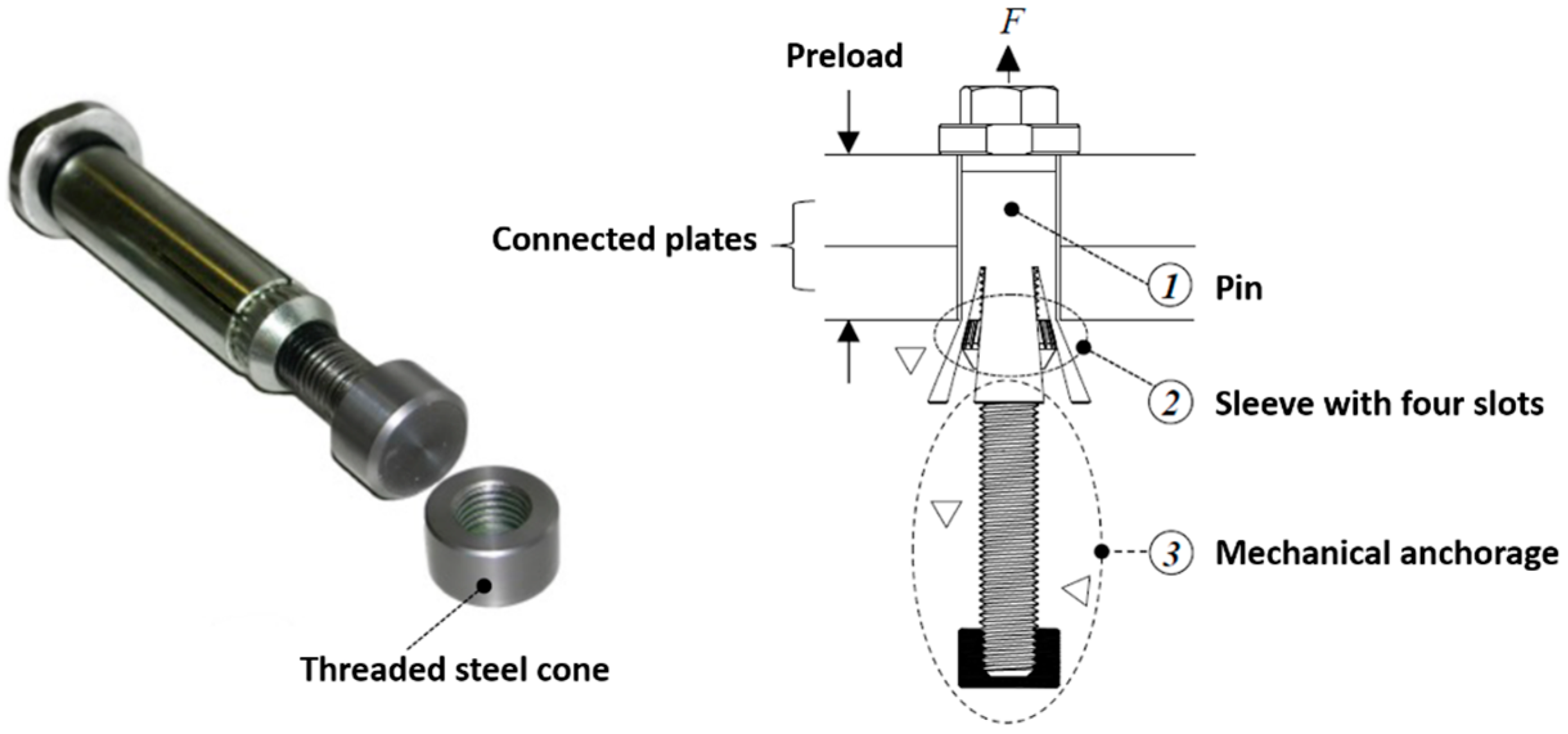
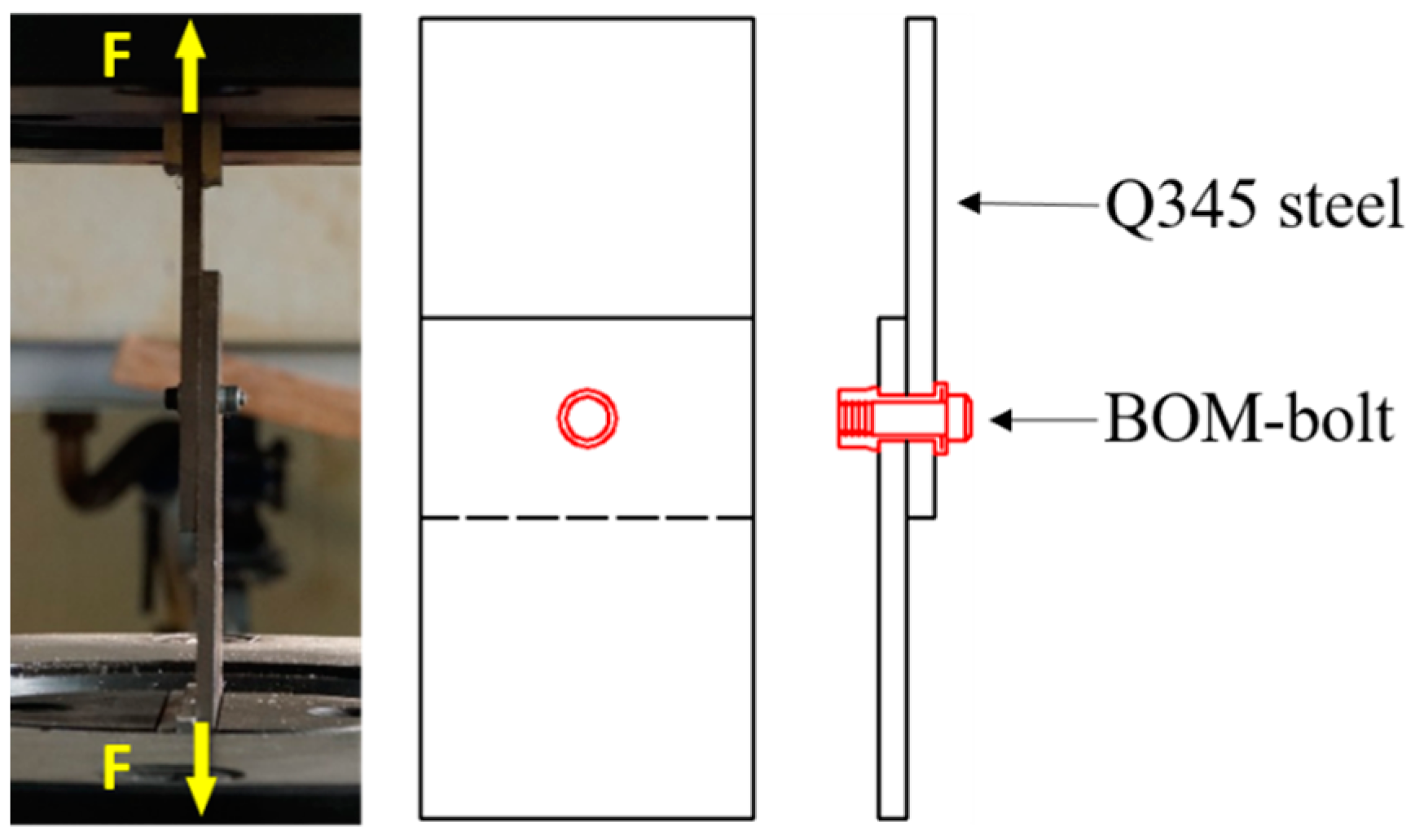
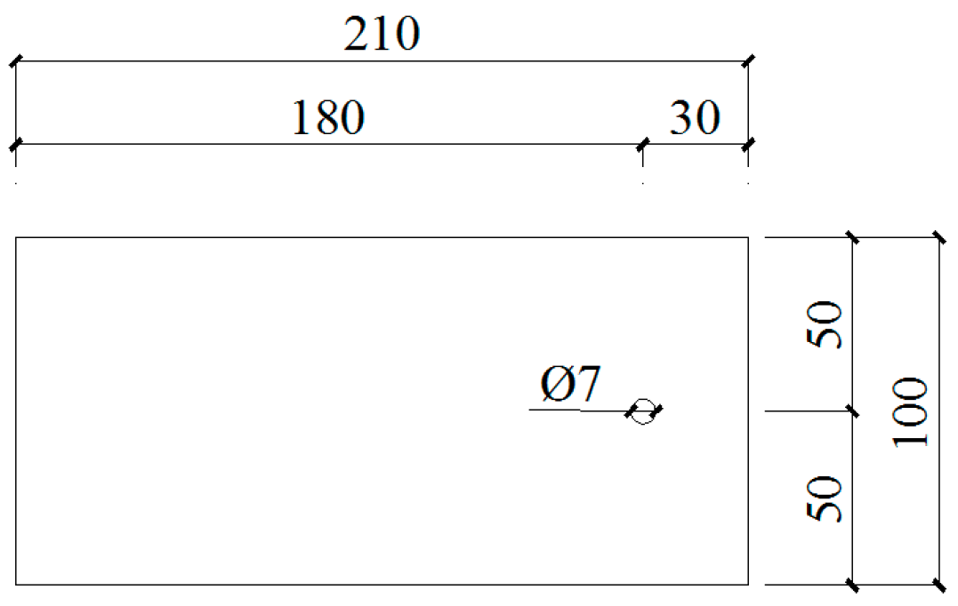
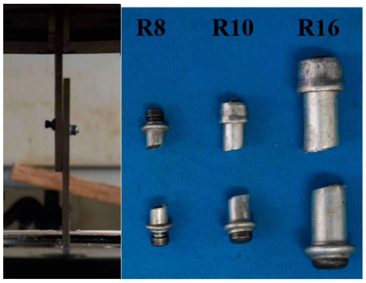
2.1. Shear Tests of Single BOM-Bolted Connections

Huck BOM-bolts were developed by Huck International and consist of a pin and a sleeve, both made of carbon steel. BOM bolts have the advantage of high tensile and shear load capacity and precise mounting positioning, making them suitable for critical joints in structures, and are environmentally safer than welding and more efficient and easier to install than conventional bolts. Figure 3 shows the construction of a BOM-bolt before and after installation.
The tests included three different bolt diameters of BOM-bolts, and three specimens of each specification were set up for nine specimens. The specific parameter settings are listed in Table 1. The material of the connection plate used for the test was Q355 steel. The purpose of the tests was to investigate the shear load capacity and damage mode of the bolts. The tests were conducted on a universal testing machine of which the setup and specimen design diagrams are shown in Figure 4 and Figure 5.
The damage mode of a single BOM-bolt specimen is the shear failure of the screw and sleeve, as shown in Figure 6. Under these test parameters, the ultimate shear capacity of the specimen is determined by the shear strength of the BOM-bolt and the measured values are shown in Table 2.

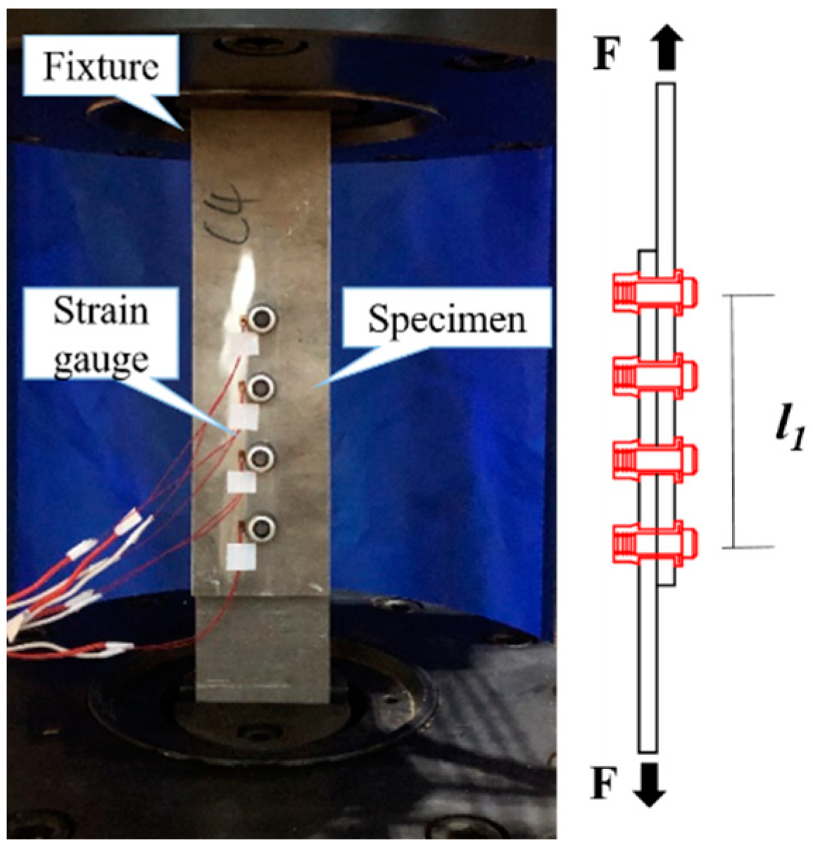
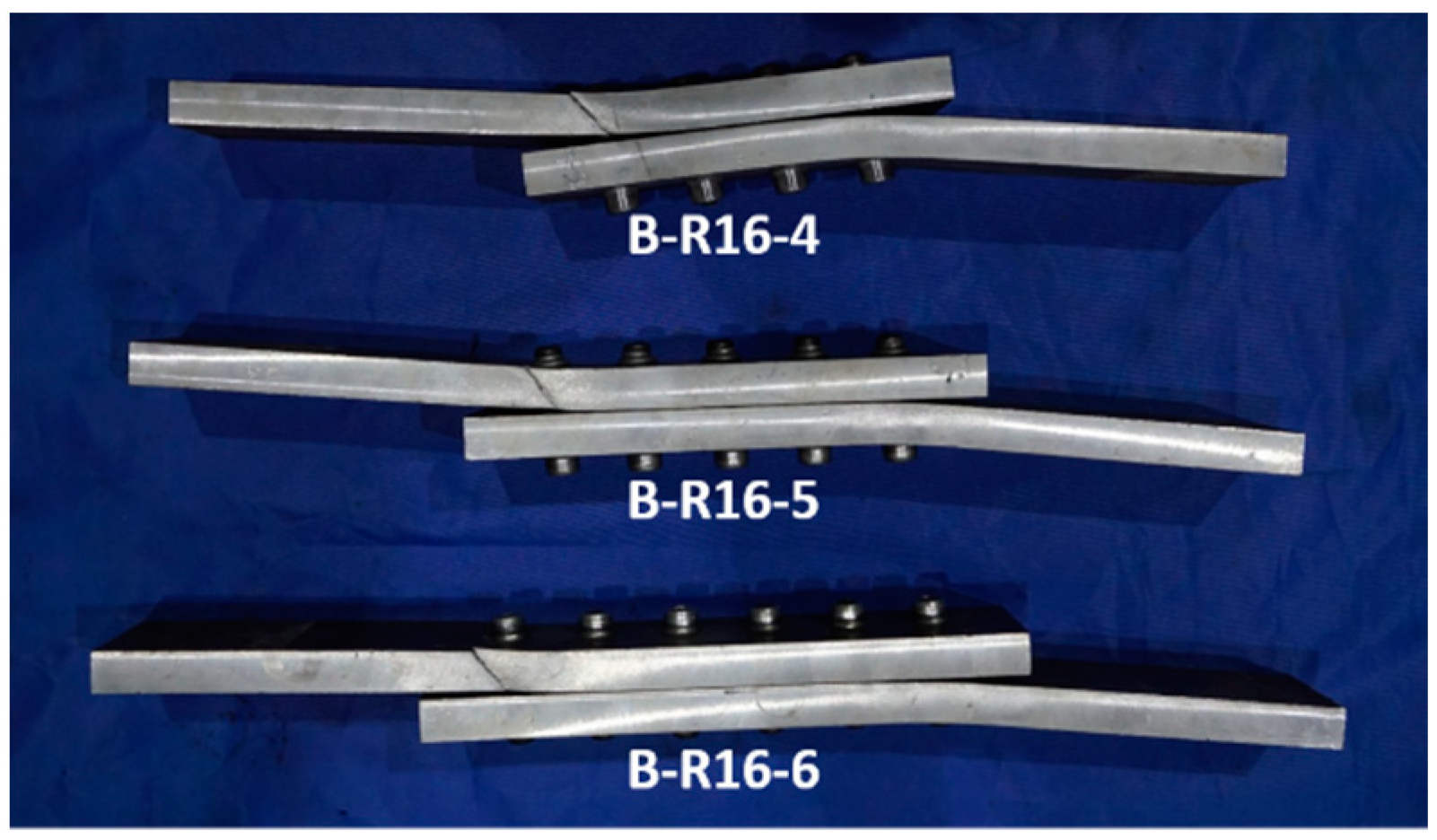
2.2. Shear Tests of BOM-Bolted Long Connections

In long connections with a large number of bolts, the distribution of shear forces on each bolt is influenced by the mechanical properties of the connected material and the way of the bolt arrangement. For materials with poor plastic deformability (e.g., high-strength steel), experimental studies have shown that the individual bolts in a bolt group are unevenly stressed during the elastic stress phase. The shear force distribution is influenced by the length and distribution form of the bolt connection [22,23]. The aluminum alloy has no significant yield steps and has a modulus of elasticity of about 1/3 that of steel, so the uneven load distribution in the bolted aluminum connection may be more pronounced than that of steel plates. The purpose of the tests in this section is to investigate how the length of the BOM-bolted connections affects the shear force distribution and to provide a database for refining the design method for aluminum alloy bolted connections.
The test included two different bolt diameters and three bolt connection lengths. One specimen was set up for each specification, making a total of six specimens. The material of the connection plate used for the test was 6061-T6 Al alloy. The specific parameter settings, test setup and specimen design are shown in Table 3 and Figure 7. The damage pattern of the specimen shown in Figure 8 was that the aluminum plate was pulled off from the bolt hole at the edge, and the BOM bolts showed no significant deformation. The stress distribution in each bolt hole at the end of the elastic phase of the specimen shown in Figure 9 could be calculated from the measured strain data. There was an obvious unevenness in the stress on the bolts in the elastic phase of each specimen, and the degree of unevenness increased with the increasing length of the connection. The closer the bolt was to both ends, the greater the stress was.

3. Test of Bearing Resistance at Bolt Holes of BOM-Bolted Connections

The research on the shear properties of ordinary and high-strength steel bolts shows that the bolt distance affects the bearing resistance of the bolted connection [24,25,26,27,28]. The formulae for calculating the degree of influence of bolt spacing on bearing resistance in Eurocode 9 [29] are the same as those in Eurocode 3 for the design of steel structures, but this factor has not been considered in the Chinese code for the design of aluminum structures. The material properties of aluminum are significantly different from those of steel. Therefore, a systematic study of the bearing resistance of aluminum should be carried out. The purpose of the tests in this section is to study the influence of end distance, edge distance and spacing on the shear performance of the connections and to provide a test basis for the derivation of the bearing strength formula.

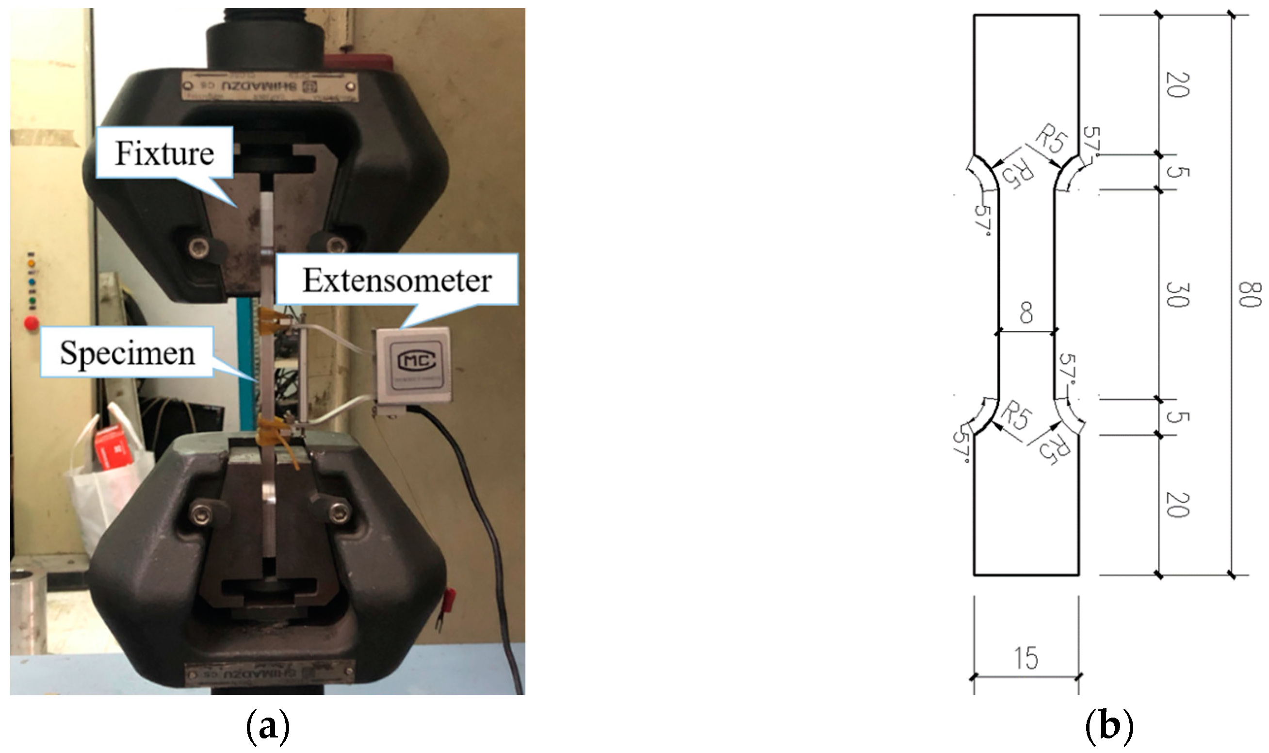
3.1. Tensile Testing of Aluminum Materials

The material tensile test was carried out on the device shown in Figure 10 with a strain gauge spacing of 25 mm used to measure strain. The specimens were taken from 6 mm thick plates for a total of three tensile specimens. The mechanical performances of the specimens obtained from the test are listed in Table 4.

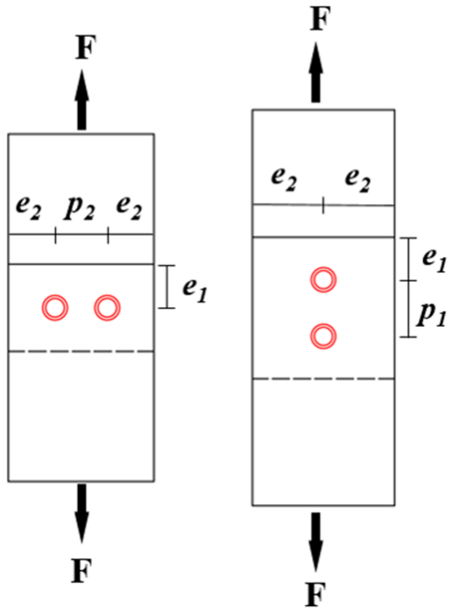
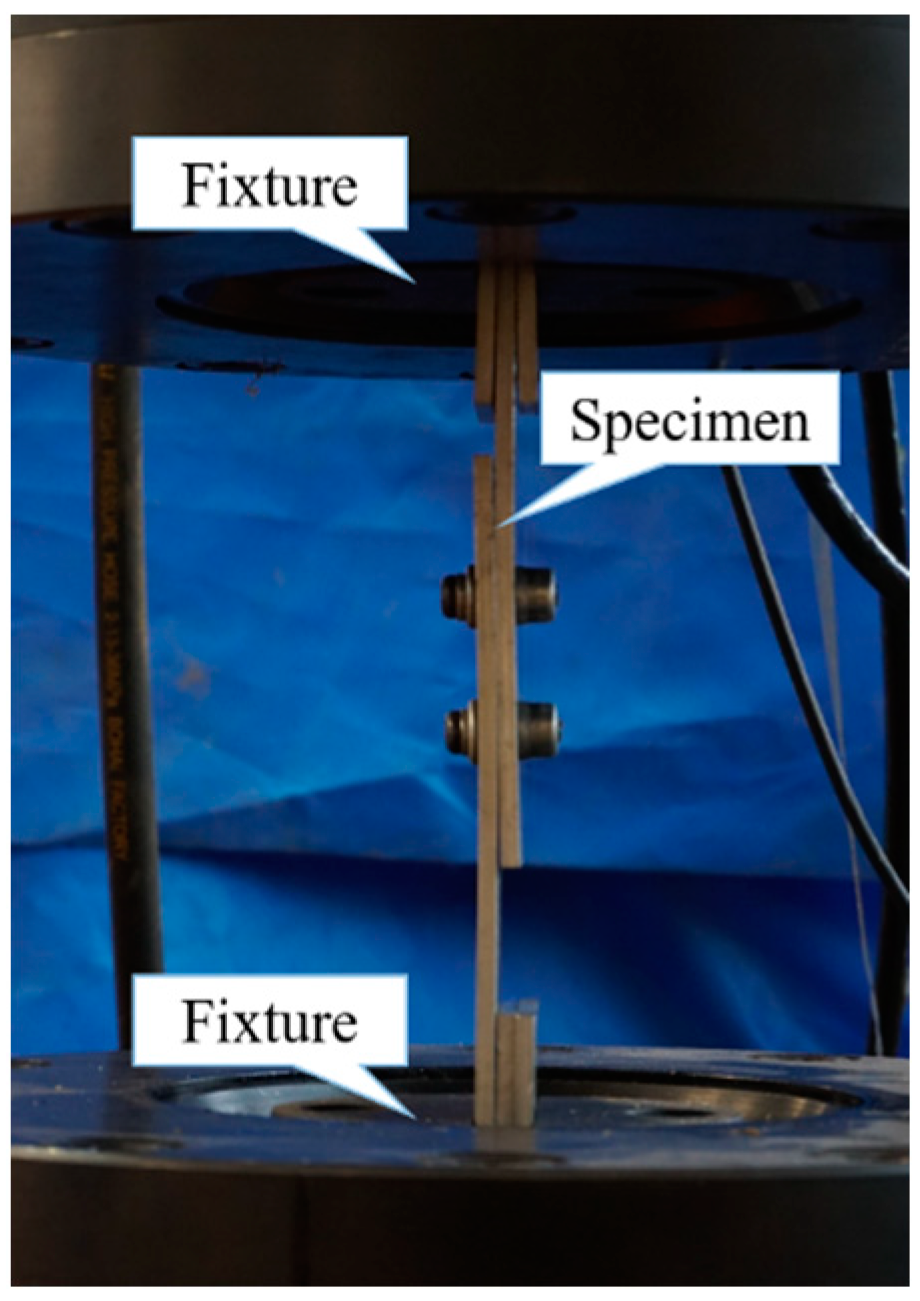
3.2. Design of the Test Setup and Parameter Scheme

The material of the plates studied in this test was 6061-T6 aluminum with a thickness of 6 mm, and two BOM bolts with a diameter of 13.6 mm were used in each connection to ensure that the bolts would not be sheared off before the aluminum plates were damaged by pressure. The test includes 13 specimens with different parameter settings listed in Table 5. There are four main parameters: end distance e1 (specimens C1, C2, C3, C4), edge distance e2 (specimens C4, C5, C6), pitch p1 (specimens C4, C7, C8, C9) and p2 (specimens C10, C11, C12, C13), and the significance of each parameter is shown in Figure 11. d0 is the diameter of the bolt hole. The end distance e1 is the distance from the edge of the plate to the center of the bolt hole and is paralleled by the direction of the load. The edge distance e2 is the distance from the edge of the plate to the center of the bolt hole and perpendicular to the direction of the load. The distance between two bolts is called the pitch, p1 and p2. The test device is shown in Figure 12.

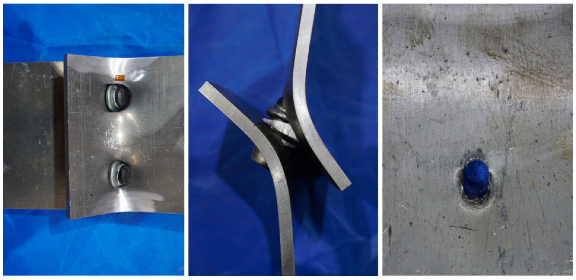
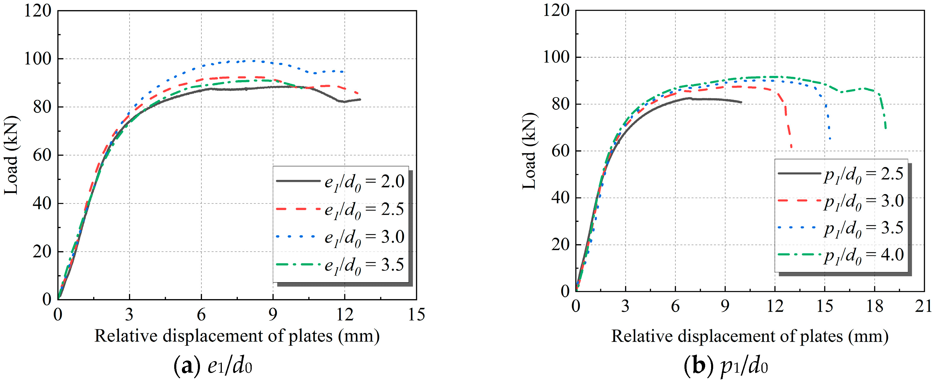
3.3. Analysis of Test Results

Within the scope of the experimental study, the specimen damage pattern shown in Figure 13 is similar where the sleeve of the BOM-bolt is sheared off, and the aluminum plate undergoes compression damage at the bolt hole. The load (F)-relative plate displacement (Δ) curves obtained from the test are shown in Figure 14. The trend of the curve reveals that with the increase in e1, e2, p1 and p2, the shear-bearing capacity of the connected members increases. The curves of the variation of the ultimate bearing capacity, Pu, and the increase in the test parameters are shown in Figure 15. Among the four parameters, the increase in the distances perpendicular to the load, e2 and p2, results in the most obvious improvement of the bearing capacity. When e2 and p2 are increased by 66% and 58%, respectively, Pu increases by 20% and 18%. When the spacing parallel to the load direction, p1, is increased by 61%, Pu increases by 11%. e1 has the least influence on the bearing capacity. e1, which has the least influence on the bearing capacity, is increased by 75%, and Pu increases by 12% only.
The ultimate bearing capacity Pu and the maximum value of average compressive stress σmax are calculated in Table 6. In the calculation of the stress of the bolt-hole wall, it is assumed that the stress is uniformly distributed and subjected to extrusion in order to facilitate the calculation, so the calculation formula for the maximum value of the average bearing strength is:
σ max = P u n b d t
where Pu is the specimen’s ultimate bearing capacity. nb is the number of bolts, which is 2 in this test. d is the diameter of the bolts, which is equal to 13.6 mm. ∑t is the thickness of the bearing plate, which is 6 mm.

3.4. Comparison of Test Results and Codes

The experimental results show the bearing strength of aluminum is influenced by the ratio of e1 to d0, e2 to d0 and the ratio of the middle distance to the bolt-hole diameter. In the Chinese aluminum code, the minimum middle distance of 2.5d0 and the minimum end distance of 2.0d0 are incorporated into the formula related to the bearing strength of Eurocode 9; the design value of the compressive strength is directly calculated, which is about 1.16 times of the material tensile strength. The influence of the bolt spacing is taken into account in Eurocode 9 when calculating the design value of the bolt bearing strength Fb,Rd, which is calculated as follows:
F b , Rd = k 1 α b f u d t γ M 2
where k1 and αb are the coefficients considering the ratio of end distance to bolt aperture and the ratio of middle distance to bolt aperture. fu is the material tensile strength. γM2 equal to 1.2 is the partial factor of aluminum material.
The values, σc,CN and σc,EU, of the bearing strength of aluminum plates calculated by the Chinese and European design code of aluminum structures are compared with the experimental value σc,test. The comparison results in Table 6 indicate that more than 80% of the calculation results of the Eurocode 9 formula are greater than the experimental values, and the average deviation is 25%. Among them, nearly half of the results exceed 40% of the experimental values, indicating that the bearing strength of aluminum calculated by the European design method is obviously larger. If this method is used to design the bearing strength of the shear connection of BOM bolts, there may be safety hazards. The bearing strength calculated according to the Chinese aluminum code is generally smaller than the test value by more than 30%, indicating that the design method is on the conservative side.

4. Finite Element Analysis of the Shear Resistance of BOM-Bolted Connections

The finite element model is constitutive of three parts: bolt pin, sleeve and aluminum plate, as shown in Figure 16. Because Model 1 is completely symmetric about the symmetry boundary to the left and right, one-half of the test specimen is used as the FEA model to improve the calculation efficiency. The constitutive model of each component is the double-fold model. The connecting plate is 6061-T6 aluminum alloy, and the mechanical properties of BOM-bolts are taken according to the properties of A325 bolts.
The model element type is a C3D8R element (three-dimensional 8-node reduced integral element). The mesh size of the bolt and sleeve is about 1 mm, and the mesh size of connecting plate is about 5 mm. There are two types of contact pairs in this model. Because the tail of the sleeve is pressed into the screw thread when the BOM bolt is installed, the contact between the two is set as the Tie constraint. The contact between the connecting plates is set to surface-to-surface contact considering the influence of friction. The friction model adopts the Coulomb model, and the anti-slip coefficient is calculated according to the relevant provisions in the aluminum code. In the tests, the testing fixtures clamped the two ends of the connecting plates and applied a large clamping force. A fixed constraint was set at the same position of the model to restore the test constraint method, and the x, y and z directions could not move and rotate. The loading method is to apply a uniform surface load at both ends of the connecting plate.
Comparing the damage modes of the finite element analysis and test (Figure 16a), it can be seen that the experimental results match the FEA ones, and the damage mode is bearing damage at the holes of the connection plate. The comparison results of F-Δ curves (Figure 17b) indicate that the errors of shear stiffness and ultimate shear bearing capacity obtained from FEA and test are within 5%, as shown in Table 7.

5. Design Method of Bearing Capacity of BOM-Bolted Aluminum Connection

5.1. Calculation Formula of Bearing Strength

On the basis of the tests in Section 3, the design method of the bearing strength of the BOM-bolted aluminum connections is proposed, and the formula for the design value of compressive bearing strength is as follows:
F c b = σ c d t / γ R
σ c = α c f u
α c = min { 0.126 e 1 d 0 + 1.36 , 0.107 p 1 d 0 + 1.26 , 0.32 e 2 d 0 + 1.07 , 0.204 p 2 d 0 + 1.07 }
where αc is the coefficient considering the effect of the distances parallel to the load, e1 and p1, and the distances perpendicular to the load, e2 and p2. fu is the aluminum tensile strength. ∑t is the smaller value of the total thicknesses of the plates in the same force direction. d is the diameter of bolts. γR is the partial coefficient of aluminum, taking the value of 1.3.
The formula of bearing strength proposed in this paper more comprehensively considers the effect of various bolt spacing perpendicular and parallel to the load direction. The value of the influence coefficient αc is chosen as the smallest value among various influencing factors, so it is more reasonable to be used to calculate the bearing strength of BOM-bolted aluminum connections, as shown in Table 8.

5.2. Reduction Formula of Shear Bearing Capacity of Long BOM-Bolted Aluminum Connection

The existing research results show that the uneven distribution of shear force in long bolted aluminum connections is more obvious than in steel connections [30]. Therefore, the reduction factor of connection length should be more stringent in aluminum shear connections. When the connection length l1 is greater than 9d0, the bearing capacity should be discounted. For the convenience of design, the calculation formula of reduction factor βs is similar to that of steel structures:
β s = 1.1 l 1 90 d 0
where l1 is the length of the connection, and d0 is the bolt-hole diameter.

6. Conclusions

The shear performance of the Huck BOM-bolt, a blind bolt used to join rectangular section elements, is thoroughly examined in this paper. The FEA approach was utilized to model and simulate the specimens while conducting shear resistance tests on single, double, and groups of bolts. The research conclusions are summarized as follows:
(1)
Shear damage to the pin and sleeve at the shear surface is the single BOM-bolt failure mode. The BOM-bolt is still in the elastic condition of force once the shear force has reached the shear design value specified in the code. The preload force is 32.5% of the code-required minimum preload force for friction-type bolts.
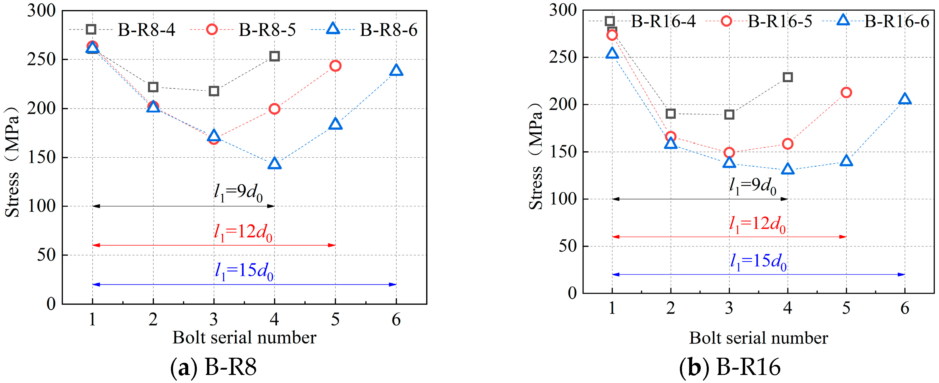
(2)
The uneven coefficient on the bolts at both ends increases by 200% as the length of the bolt connection grows by 67%. When the connection length is 15d0, the stress on the bolts at both ends is almost twice as great as that on the central bolt, which causes the end bolts to break down more quickly. Therefore, the design value of the bolt shear bearing strength should be partially discounted when the connection length exceeds 9d0.
(3)
The spacing between the bolts affects the bearing strength of the connected aluminum plates, and the distances parallel to the load, e1 and p1, have less of an impact than those perpendicular to the load, e2 and p2. e2 and p2 rise by around 60%, and the specimen’s carrying capacity Pu rises by about 20%. Pu rises by 11% whereas p1 rises by 61%. Pu barely increases by 12% while e1, which has the least impact on bearing capacity, increases by 75%.
(4)
There is a significant discrepancy between the test results and the ones obtained according to the calculation method of bolt-bearing strength in the Chinese and European codes of aluminum structures. The results of the European code calculation are approximately 25% higher than the test findings. There may be safety risks if it is utilized to design the bearing strength of the shear connection of BOM bolts. The Chinese code’s calculation of bearing strength is typically more than 30% lower than test values, demonstrating that the design approach is cautious and prone to material waste.
(5)
The shear performance of BOM-bolted connections is simulated by the FEM and is confirmed by contrasting it with the outcomes of experiments. The comparison results of failure modes and F-Δ curves demonstrate that the FEM accurately simulates the shear performance of the specimens.
(6)
Based on the test results, the design method of the bearing strength of BOM-bolted aluminum connections and the reduction formula of the shear bearing capacity of long-bolted connections are provided. The errors between the test values and the calculated values are less than 5%, which indicates that the formula is suitable for calculating the bearing strength of BOM-bolted aluminum connections. The study of the shear properties of BOM bolts in this paper is to provide a research basis for the application of BOM bolts in aluminum alloy spatial structure joints. Subsequently, the mechanical properties of BOM-bolted aluminum joints will be investigated.

Author Contributions

Literature search, Y.J. and Z.Z.; figures, Y.J. and Z.Z.; study design, Y.J. and H.M.; data collection, Y.J., Z.Z. and P.C.; data analysis, Y.J., H.M. and P.C.; data interpretation, Y.J.; writing, Y.J.; review and editing, H.M., Z.Z. and P.C. All authors have read and agreed to the published version of the manuscript.

Funding

This research was supported by the National Key R&D Program of China (grant no. 2021YFC3100800, 2021YFC3100803), and Natural Science Foundation of Guangdong Province of China (grant no. 2023A1515011022).

Data Availability Statement

The data presented in this study are available on request from the corresponding author. The data are not publicly available due to privacy.

Conflicts of Interest

The authors declare no conflict of interest. The funders had no role in the design of the study; in the collection, analyses, or interpretation of data; in the writing of the manuscript; or in the decision to publish the results.

References

  1. Barnett, T.C.; Tizani, W.; Nethercot, D.A. The practice of blind bolting connections to structural hollow sections: A review. Steel Compos. Struct. 2001, 1, 1–16. [Google Scholar] [CrossRef]
  2. France, J.E.; Davison, J.B.; Kirby, P.A. Strength and rotational stiffness of simple connections to tubular columns using flowdrill connectors. J. Constr. Steel Res. 1999, 50, 15–34. [Google Scholar] [CrossRef]
  3. Ballerini, M.; Piazza, M.; Bozzo, E.; Occhi, F. Shear capacity of blind bolted connections for RHS steel structural elements. In Proceedings of the Seventh International Symposium, Miskolc, Hungary, 28–30 August 1996; Balkema: Rotterdam, The Netherlands, 1996; pp. 99–106. [Google Scholar]
  4. France, J.E.; Davison, J.B.; Kirby, P.A. Strength and rotational response of moment connections to tubular columns using flowdrill connectors. J. Constr. Steel Res. 1999, 50, 1–14. [Google Scholar] [CrossRef]
  5. France, J.E.; Davison, J.B.; Kirby, P.A. Moment-capacity and rotational stiffness of endplate connections to concrete-filled tubular columns with flowdrilled connectors. J. Constr. Steel Res. 1999, 50, 35–48. [Google Scholar] [CrossRef]
  6. Slowinski, K.; Wuwer, W. Blind-bolted shear connections for axially compressed RHS columns strengthened with open sections. J. Constr. Steel Res. 2016, 127, 15–27. [Google Scholar] [CrossRef]
  7. Mourad, S. Behaviour of Blind Bolted Moment Connections for Square HSS Columns. Doctoral Dissertation, McMaster University, Hamilton, ON, Canada, 1994; pp. 12–49. [Google Scholar]
  8. Korol, R.M.; Ghobarah, A.; Mourad, S. Blind Bolting W-Shape Beams to HSS Columns. J. Struct. Eng. 1993, 119, 3463–3481. [Google Scholar] [CrossRef]
  9. Mourad, S.; Ghobarah, A.; Korol, R.M. Dynamic response of hollow section frames with bolted moment connections. Eng. Struct. 1995, 17, 737–748. [Google Scholar] [CrossRef]
  10. Mourad, S.; Korol, R.M.; Ghobarah, A. Design of extended end-plate connections for hollow section columns. Can. J. Civ. Eng. 2011, 23, 277–286. [Google Scholar] [CrossRef]
  11. Ghobarah, A.; Mourad, S.; Korol, R.M. Moment-rotation relationship of blind bolted connections for HSS columns. J. Constr. Steel Res. 1996, 40, 63–91. [Google Scholar] [CrossRef]
  12. Mourad, S. Resistance factors for blind bolts in direct tension. Eng. Struct. 1997, 19, 995–1000. [Google Scholar]
  13. Tizani, W.; Cabrera, M.; Mahmood, M.; Ninic, J.; Wang, F. The behaviour of anchored extended blind bolts in concrete-filled tubes. Steel Constr. Des. Res. 2022, 15, 51–58. [Google Scholar] [CrossRef]
  14. Waqas, R.; Uy, B.; Thai, H.T. Experimental and numerical behaviour of blind bolted flush endplate composite connections. J. Constr. Steel Res. 2019, 153, 179–195. [Google Scholar] [CrossRef]
  15. Cabrera, M.; Tizani, W.; Ninic, J. A Review and Analysis of Testing and Modeling Practice of Extended Hollo-Bolt Blind Bolt Connections. J. Constr. Steel Res. 2021, 183, 106763. [Google Scholar] [CrossRef]
  16. Mahmood, M.; Tizani, W. A component model for column face in bending of extended HolloBolt connections. J. Constr. Steel Res. 2021, 182, 106655. [Google Scholar] [CrossRef]
  17. Debnath, P.P.; Chan, T.M. Tensile behaviour of headed anchored hollo-bolts in concrete filled hollow steel tube connections. Eng. Struct. 2021, 234, 111982. [Google Scholar] [CrossRef]
  18. Tizani, W.; Mahmood, M.; Bournas, D.A. Effect of Concrete Infill and Slenderness on Column-Face Component in Anchored Blind-Bolt Connections. J. Struct. Eng. 2020, 146, 04020041.1–04020041.18. [Google Scholar] [CrossRef]
  19. Wang, Y.; Wang, Z.; Pan, J.; Wang, P. Nonlinear Finite Element Analysis of Anchored Blind-Bolted Joints to Concrete-Filled Steel Tubular Columns. Int. J. Perform. Eng. 2019, 15, 676–687. [Google Scholar] [CrossRef]
  20. Wang, Y.; Wang, Z.; Pan, J.; Wang, P.; Qin, J.; Chen, S. Cyclic Behavior of Anchored Blind-Bolted Extended End-Plate Joints to CFST Columns. Appl. Sci. 2020, 10, 904. [Google Scholar] [CrossRef] [Green Version]
  21. Guo, L.; Wang, J.; Wang, W.; Duan, M. Seismic evaluation and calculation models of CFDST column blind bolted to composite beam joints with partial shear interaction. Eng. Struct. 2019, 196, 109269.1–109269.20. [Google Scholar] [CrossRef]
  22. Kim, H.J.; Yura, J.A. The effect of ultimate-to-yield ratio on the bearing strength of bolted connections. J. Constr. Steel Res. 1999, 49, 255–269. [Google Scholar] [CrossRef]
  23. Rex, C.O.; Easterling, W.S. Behavior and Modeling of a Bolt Bearing on a Single Plate. J. Struct. Eng. 2003, 129, 792–800. [Google Scholar] [CrossRef]
  24. Kiyokawa, S.; Tateishi, K.; Hanji, T.; Shimizu, M. Slip Coefficient and Ultimate Strength of High-Strength Bolted Friction Joints with Compact Bolt Spacing and Edge Distance. Int. J. Steel Struct. 2019, 19, 1191–1201. [Google Scholar] [CrossRef]
  25. Bae, M.W.; Kim, S.M. A Study on Characteristics of Magnitude and Distribution Area for Contact Pressure Relative to Separated Distance from Bolt Center by Tightening Torque of Flange Bolt. Trans. Korean Soc. Mech. Eng. A 2018, 42, 621–629. [Google Scholar] [CrossRef]
  26. Moze, P. Bearing strength at bolt holes in connections with large end distance and bolt pitch. J. Constr. Steel Res. 2018, 147, 132–144. [Google Scholar] [CrossRef]
  27. Liang, G.; Guo, H.; Liu, Y.; Yang, D.; Li, S. A comparative study on tensile behavior of welded T-stub joints using Q345 normal steel and Q690 high strength steel under bolt preloading cases. Thin-Walled Struct. 2019, 137, 271–283. [Google Scholar] [CrossRef]
  28. Xu, Z.; Gan, Z.; Xiao, D.; Deng, C. Research on Performance of Channel Connections with Different Bolt Edge Distances. Ind. Constr. 2018, 48, 162–167. [Google Scholar]
  29. EN 1999-1-1: 2014; Eurocode 9: Design of Aluminum Structures. Springer: Berlin/Heidelberg, Germany, 2014.
  30. Shi, Y.; Zhang, G.; Wang, Y. Shear Resistance of Bolted Connection in Aluminum Structures. Prog. Steel Build. Struct. 2008, 10, 1–7. [Google Scholar]
Figure 1. Constructions of the HSBB and BOM bolts [6,7].
Metals 13 01337 g001
Figure 2. Constructions of the Lindapter Hollobolt before and after installation [13].
Metals 13 01337 g002
Figure 3. Constructional drawing of BOM bolt.
Metals 13 01337 g003
Figure 4. Schematic diagram test setup of shear tests of single BOM bolt.
Metals 13 01337 g004
Figure 5. Layouts of Q355 steel connection plates.
Metals 13 01337 g005
Figure 6. Layouts of Q355 steel connection plates.
Metals 13 01337 g006
Figure 7. Test setup of shear tests of BOM-bolted members.
Metals 13 01337 g007
Figure 8. Failure modes of BOM-bolted members in shear tests.
Metals 13 01337 g008
Figure 9. Relationship between the non-uniformity coefficient of shear force and bolt arrangement.
Metals 13 01337 g009
Figure 10. Material tests of aluminum alloy connecting plate. (a) Loading and measuring device. (b) Specimen size.
Metals 13 01337 g010
Figure 11. Diagram of parameter settings of aluminum connections.
Metals 13 01337 g011
Figure 12. Test setup of aluminum connections.
Metals 13 01337 g012
Figure 13. Failure modes of pressure test of aluminum alloy plates.
Metals 13 01337 g013
Figure 14. Load-displacement curves of pressure test of aluminum alloy plates.
Metals 13 01337 g014aMetals 13 01337 g014b
Figure 15. Curves of ultimate bearing capacity changing with test parameters. (a) e1/d0. (b) p1/d0. (c) e2/d0. (d) p2/d0.
Metals 13 01337 g015
Figure 16. Finite element models of shear connections of BOM bolts.
Metals 13 01337 g016
Figure 17. Comparison of results of pressure test of aluminum plate obtained from test and FEA. (a) Damage mode. (b) Load-displacement curves.
Metals 13 01337 g017
Table 1. Parameter setup of shear tests of single BOM bolt.
Specimen NumberBolt Diameter
d (mm)
Bolt Hole Diameter
d0 (mm)
Thickness of
Connecting Plate t (mm)
A-R8-16.876
A-R8-2
A-R8-3
A-R10-18.6910
A-R10-2
A-R10-3
A-R16-113.61420
A-R16-2
A-R16-3
Table 2. Shear capacity of BOM bolts.
Specimen NumberShear Capacity (kN)
A-R8-126.7
A-R8-225.0
A-R8-325.3
A-R10-139.9
A-R10-240.4
A-R10-341.1
A-R16-1143.0
A-R16-2132.8
A-R16-3133.2
Table 3. Parameter setup of shear tests of BOM-bolted members.
Specimen NumberBolt Diameter
d (mm)
Bolt Hole Diameter
d0 (mm)
Bolt QuantityConnection Length
l1 (mm)
B-R8-46.8749d0
B-R8-5512d0
B-R8-6615d0
B-R16-413.61449d0
B-R16-5512d0
B-R16-6615d0
Table 4. Mechanical performances of aluminum specimens.
Thickness of PlateSpecimen NumberElastic ModulusYield StrengthTensile Strengthf0.2/fu
6 mm168,138 MPa263.1 MPa322.9 MPa0.81
269,027 MPa260.5 MPa323.9 MPa0.80
361,615 MPa246.8 MPa319.2 MPa0.77
Table 5. Parameter setup of bearing strength at bolt holes of aluminum alloy plates.
Specimen Numbere1e2p1p2
C12.0d02.5d04.0d0
C22.5d02.5d04.0d0
C33.0d02.5d04.0d0
C43.5d02.5d04.0d0
C53.0d01.5d04.0d0
C63.0d02.0d04.0d0
C73.0d02.5d02.5d0
C83.0d02.5d03.0d0
C93.0d02.5d03.5d0
C103.0d02.5d02.5d0
C113.0d02.5d03.0d0
C123.0d02.5d03.5d0
C133.0d02.5d04.0d0
Table 6. Parameter setup of bearing strength at bolt holes of aluminum alloy plates.
Specimen NumberPu
(kN)
σc,test
(MPa)
σc,CN
(MPa)
σc,EU
(MPa)
σc,CN/σc,testσc,EU/σc,test
C188.5542.3373.5523.30.690.96
C291.2558.8373.5659.50.671.18
C392.6567.4373.5799.30.661.41
C499.2607.8373.5805.00.611.32
C582.5505.5373.5763.40.741.51
C690.9557.0373.5805.00.671.45
C783.6512.3373.5578.00.731.13
C887.7537.4373.5801.10.701.49
C987.9538.6373.5801.20.691.49
C1082.6506.1373.5468.60.740.93
C1187.5536.2373.5601.80.701.12
C1290.2552.7373.5737.90.681.34
C1391.7561.9373.5797.30.661.42
Table 7. Comparison of the aluminum compressive strength from test and different formulas.
Specimen NumberTest Values σc,test (MPa)FEA Value σc,FEA (MPa)σc,f/σc,test
C1542.3528.10.97
C2558.8537.20.96
C3567.4554.80.98
C4607.8572.90.94
C5505.5510.31.01
C6557.0536.30.96
C7512.3493.70.96
C8537.4524.40.98
C9538.6549.61.02
C10506.1483.00.95
C11536.2511.60.95
C12552.7533.80.97
C13561.9548.70.98
Table 8. Comparison of the aluminum compressive strength from test and different formulas.
Specimen NumberTest Values σc,test (MPa)Formula Value σc,f (MPa)σc,f/σc,test
C1542.3522.70.96
C2558.8543.30.97
C3567.4564.41.00
C4607.8582.30.96
C5505.5488.70.97
C6557.0547.20.98
C7512.3494.80.97
C8537.4527.90.98
C9538.6562.01.05
C10506.1494.90.98
C11536.2512.00.95
C12552.7529.40.96
C13561.9547.40.97
Disclaimer/Publisher’s Note: The statements, opinions and data contained in all publications are solely those of the individual author(s) and contributor(s) and not of MDPI and/or the editor(s). MDPI and/or the editor(s) disclaim responsibility for any injury to people or property resulting from any ideas, methods, instructions or products referred to in the content.

