
Two-Step Spin Forming of Thin-Walled Heads with Lateral Normal Flanged Holes

Abstract
:1. Introduction
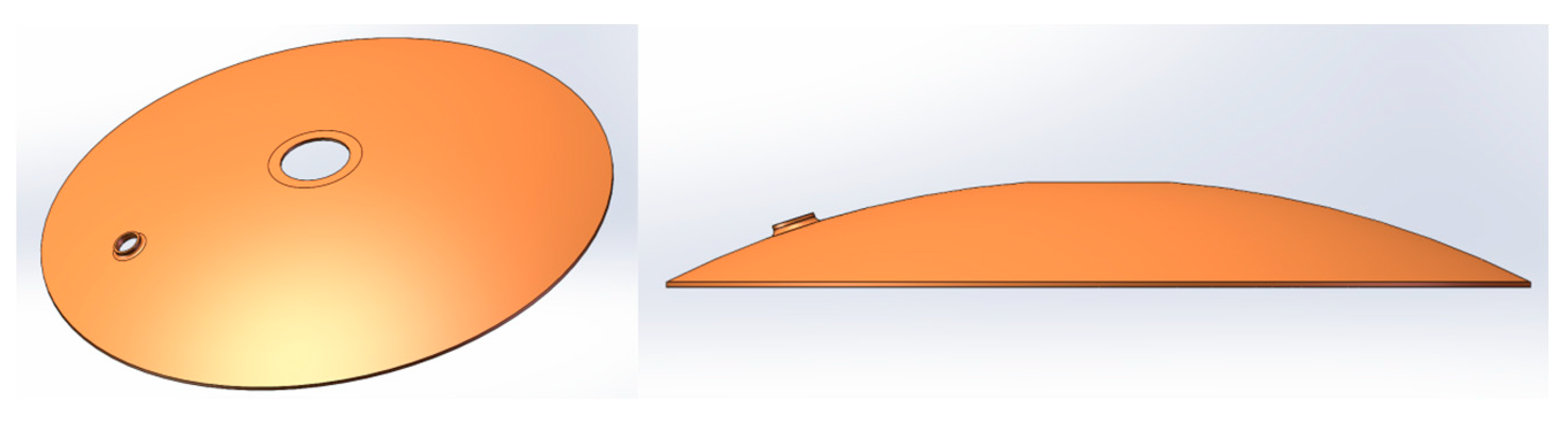
2. A Two-Step Spinning Method for Thin-Walled Heads with Lateral Normal Flanged Holes
3. Development and Verification of the Finite Element Model (FEM)
3.1. Development of the FEM
3.2. Verification of the FEM Model
4. Results and Discussion
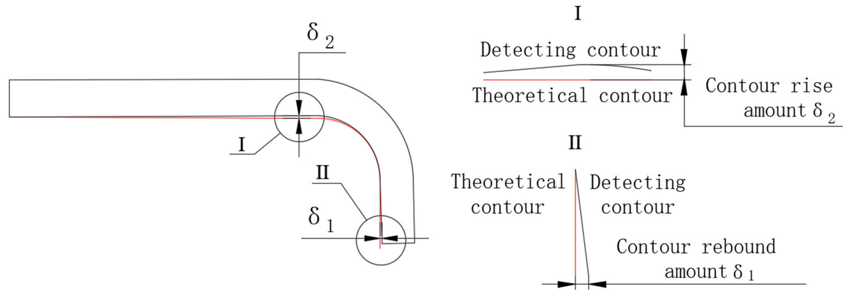
4.1. Evaluation Index of Punching–Spinning Flanging Accuracy
4.2. Influence of the Punching–Spinning Flanging Process Parameters on the Forming Accuracy
4.2.1. Effect of the Thinning Ratio on the Forming Accuracy
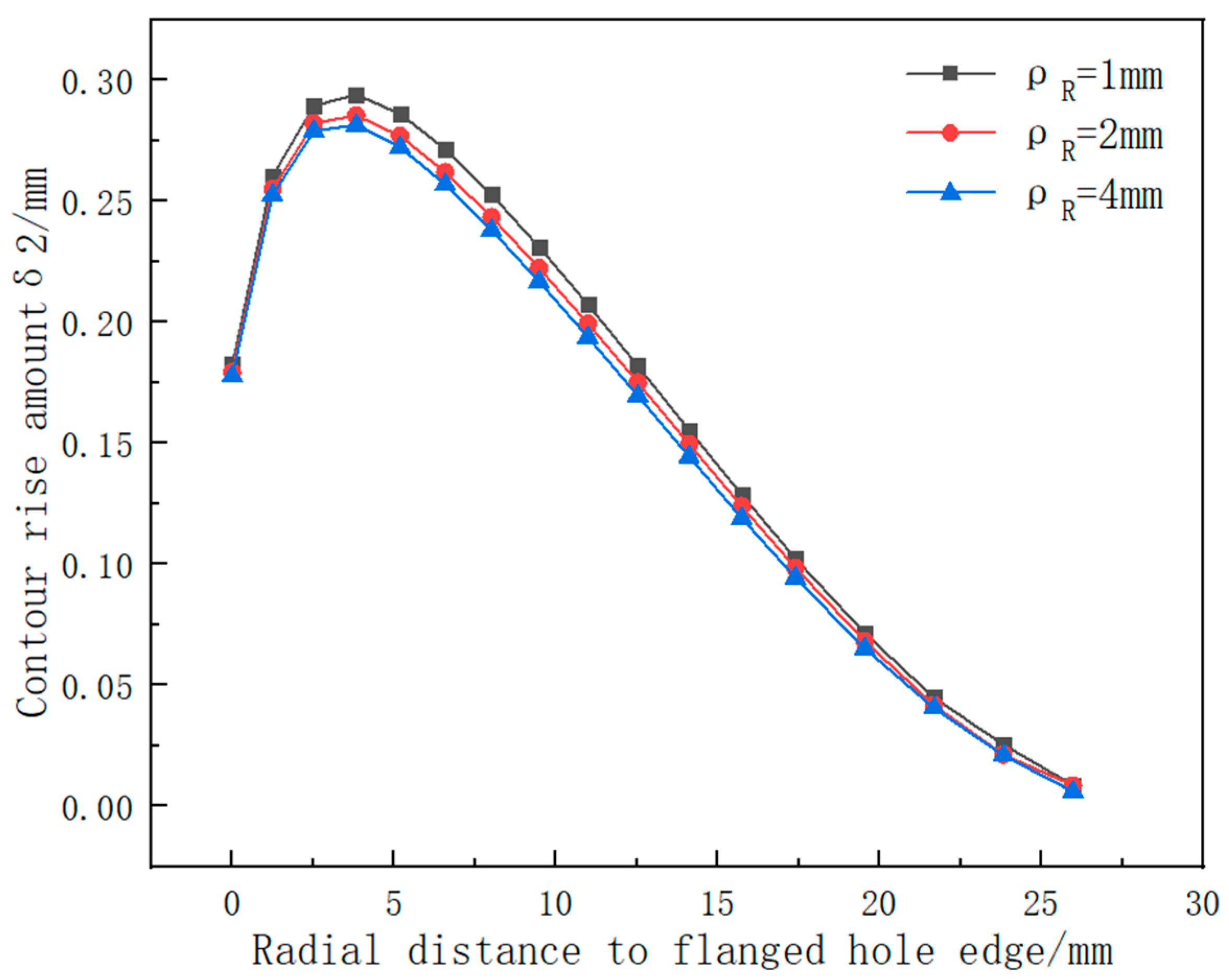
4.2.2. Influence of the Roller Fillet Radius on the Forming Accuracy
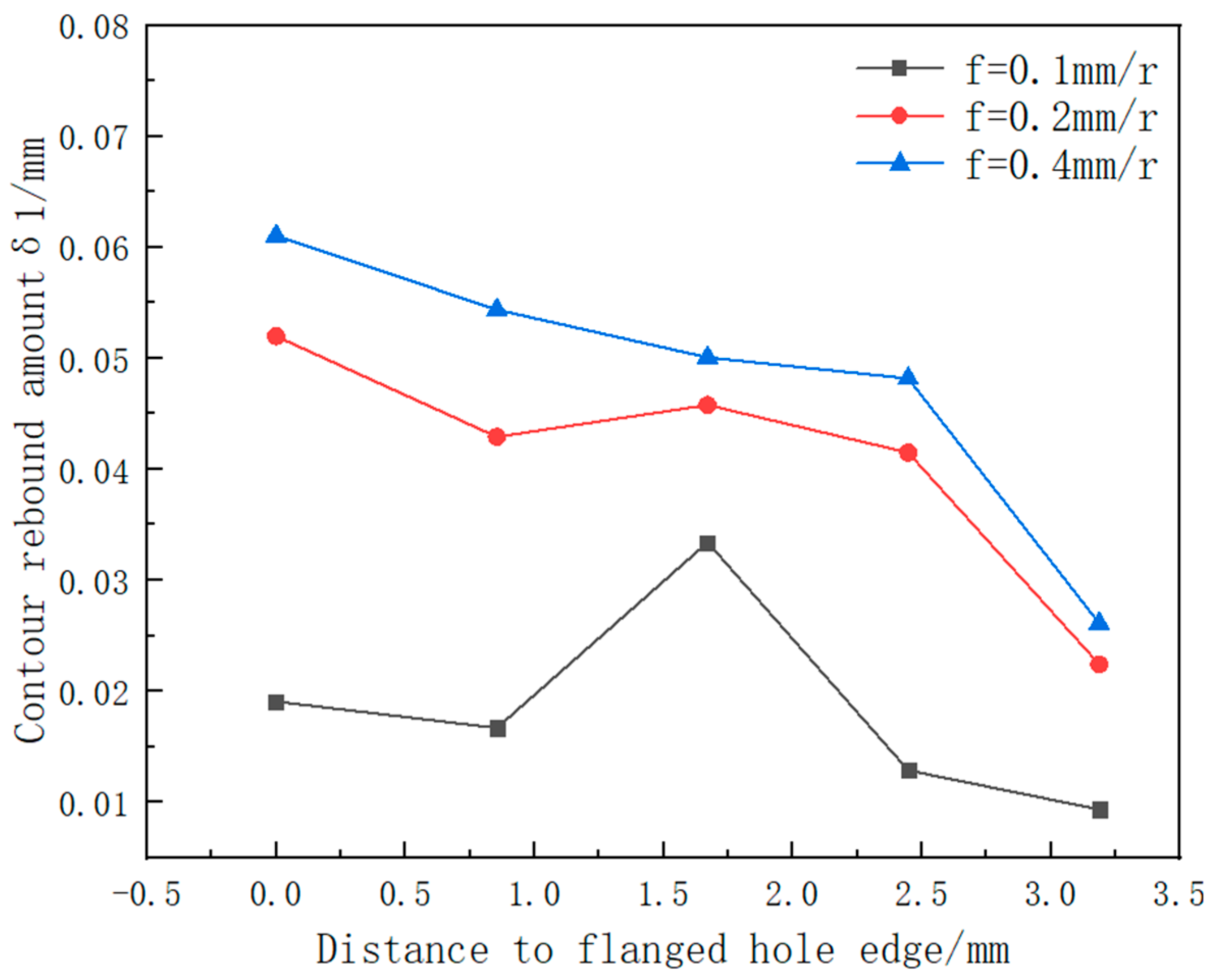
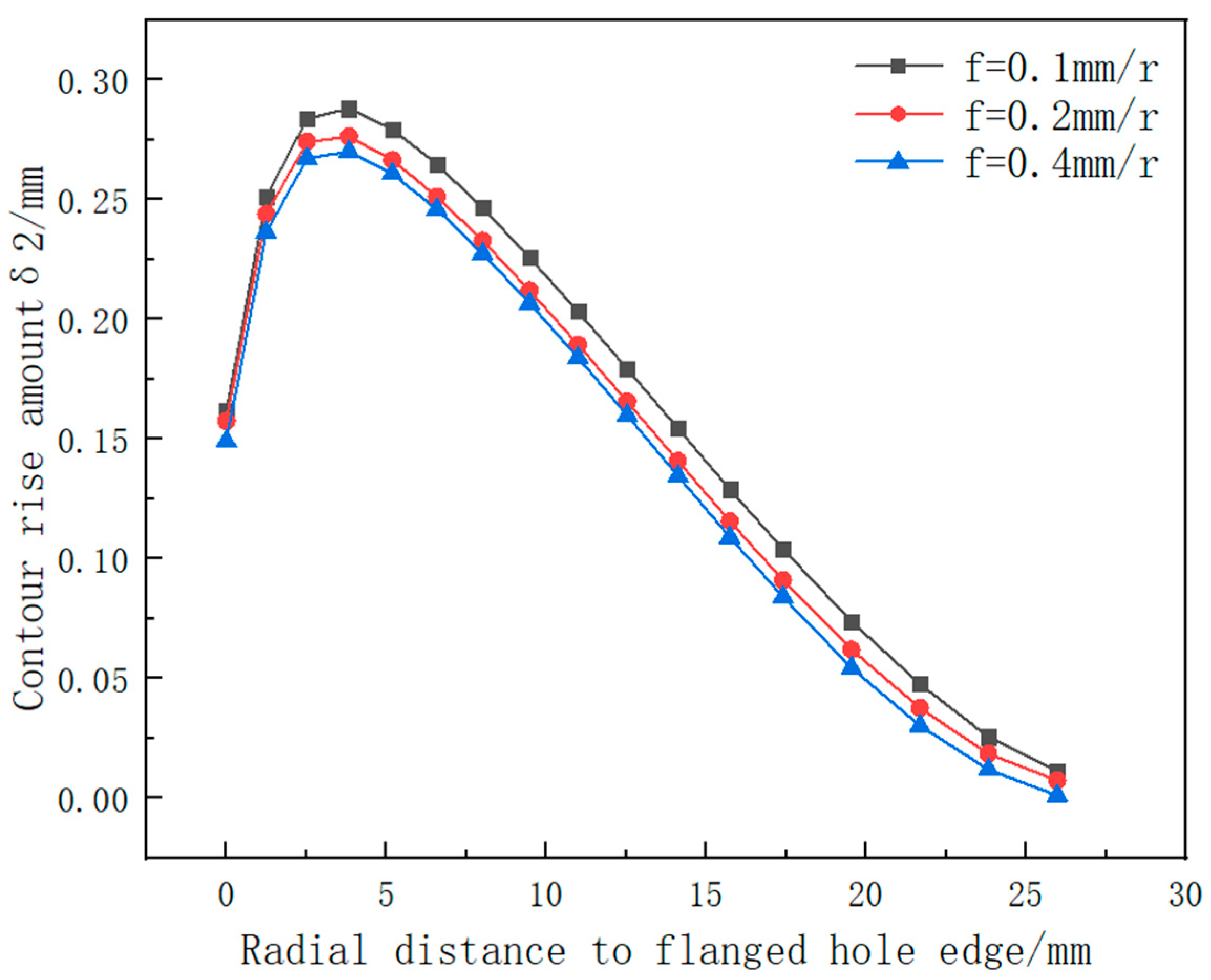
4.2.3. Influence of the Feed Ratio on the Forming Accuracy
4.3. The Influence of Punching–Spinning Flanging on the Accuracy of the Thin-Walled Head Contour
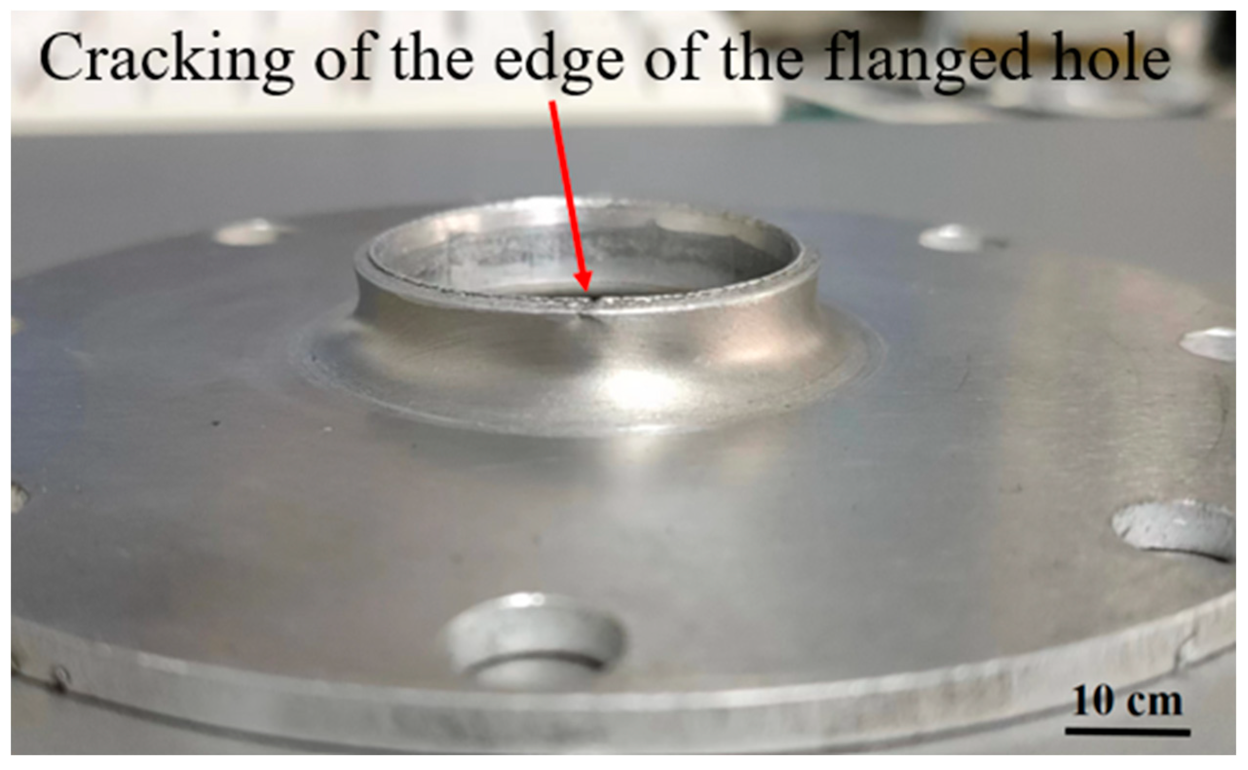
4.4. Experimental Verification
5. Conclusions
Author Contributions
Funding
Institutional Review Board Statement
Informed Consent Statement
Data Availability Statement
Conflicts of Interest
References
- Yuan, S.J. Fundamental and processes of fluid pressure forming technology for complex thin-walled components. Engineering 2021, 7, 189–206. [Google Scholar] [CrossRef]
- Yao, J.S.; Cai, Y.F.; Li, C.G. Development and application of launch vehicle body structure manufacturing technology. Aerosp. Manuf. Technol. 2007, 10, 36–40. [Google Scholar]
- Zocca, A.; Wilbig, J.; Waske, A.; Günster, J.; Widjaja, M.P.; Neumann, C.; Clozel, M.; Meyer, A.; Ding, J.; Zhou, Z.; et al. Challenges in the Technology Development for Additive Manufacturing in Space. Chin. J. Mech. Eng. Addit. Manuf. Front. 2022, 42, 23–34. [Google Scholar] [CrossRef]
- Gong, J.R.; Yang, Y.; Fan, H.M. Experimental study on the bottom flap forming of hard state tanks. Aerosp. Manuf. Technol. 2022, 1, 11–15. [Google Scholar]
- Liu, J.J.; Gao, J.Z. Simulation study on the wall thickness distribution and flap height of the outer edge flap of 1060 aluminum sheet progressive forming. Forg. Press. Technol. 2021, 46, 56–61. [Google Scholar]
- Lu, S.H.; Fu, J.Y.; Ding, T.F. Research status of CNC progressive forming process for sheet metal. Forg. Press. Technol. 2022, 47, 2199–2214. [Google Scholar]
- Zhang, X.L.; Guo, H.; Zhao, H.F. Heating flanging process of quenched 2219 aluminum alloy plates. Forg. Press. Technol. 2021, 46, 136–140. [Google Scholar]
- Zhao, Y. Research on Hot Forming of Flanged Edges with Uniform Wall Thickness; Harbin Institute of Technology: Harbin, China, 2020. [Google Scholar]
- Yu, H.; Zheng, Q.; Wang, S. The deformation mechanism of circular hole flanging by magnetic pulse forming. J. Mater. Process. Technol. 2018, 257, 54–64. [Google Scholar] [CrossRef]
- Cui, X.H.; Qiu, D.Y.; Yan, Z.C. Electromagnetic flap forming of sheet material with magnet collector structure. J. Plast. Eng. 2021, 28, 44–52. [Google Scholar]
- He, Z. Research on Ball Spinning Flanging Process and Design of Specialized Device; Yanshan University: Yanshan, China, 2017. [Google Scholar]
- Zhang, H.R.; Zhan, M.; Zheng, Z.R.; Li, R. Development and challenges of forming and manufacturing technology for large thin-walled rotary surface components in aerospace. J. Mech. Eng. 2022, 58, 166–185. [Google Scholar]
- López-Fernández, J.A.; Centeno, G.; Vallellano, C. Wrinkling in shrink flanging by single point incremental forming. Int. J. Mech. 2023, 240, 107930. [Google Scholar] [CrossRef]
- Hu, Z.Q.; Da, L.J.; Li, X.C.; Xi, J. Evaluation on forming process of AZ31 alloy complex curved surfaces by clustering balls spinning method. Int. J. Adv. Manuf. Technol. 2022, 120, 6301–6313. [Google Scholar] [CrossRef]
- Cui, X.L.; Zhan, M.; Gao, P.F. Influence of blank flatness on the forming characteristics in the spinning of aluminum alloy thin-walled special head. Int. J. Adv. Manuf. Technol. 2020, 107, 59–66. [Google Scholar] [CrossRef]
- Yan, X.G.; Zhan, M.; Wang, Y.; Gao, P.F.; Wang, Y.D. Criterion and processing-dependence of forming states in the die-less spinning of conical part. Int. J. Adv. Manuf. Technol. 2023, 125, 3037–3051. [Google Scholar] [CrossRef]
- Zhou, L.; Yang, G.P.; Liu, F.C. Integral spin-forming technology for ultra-large diameter box bottoms. Forg. Press. Technol. 2021, 46, 151–157. [Google Scholar]
- Zhang, H.R.; Zhan, M.; Zheng, Z.B.; Li, R.; Ma, F.; Cui, X.; Chen, S.; Lei, Y. Forming dependence on spin roller paths for thin-walled complex components from 2195 Al-Li alloy TWBs. Int. J. Adv. Manuf. Technol. 2022, 120, 3113–3122. [Google Scholar] [CrossRef]
- Zhou, L.; Li, X.H.; Yu, D.H.; Hu, X.J. Instability study of spherical crown thin-walled dome under small thinning rate working condition. Forg. Technol. 2016, 41, 25–31. [Google Scholar]
- Keneshlou, M.; Biglari, F.R.; Shafaie, M. A numerical and experimental analysis of noncircular blank spinning. J. Manuf. Process. 2023, 94, 159–182. [Google Scholar] [CrossRef]
- Meng, Y.H.; Yu, X.P.; Lai, Z.L.; Zhao, Y.X.; Yu, Z.Q. Spinning deformation mechanism of aluminum alloy cylinder with multi-level stiffeners based on numerical simulation. IOP Conf. Ser. Mater. Sci. Eng. 2022, 1270, 012038. [Google Scholar] [CrossRef]
- Saran, S.; Baran, L.; Mdal, Q.M. Free convection flow of hybrid ferrofluid past a heated spinning cone. Therm. Sci. Eng. Prog. 2022, 32, 101335. [Google Scholar] [CrossRef]
- Li, L.B.; Chen, S.Y.; Lu, Q.Y.; Shu, X.D.; Zhang, J.; Shen, W.W. Effect of Process Parameters on Spinning Force and Forming Quality of Deep Cylinder Parts in Multi-Pass Spinning Process. Metals 2023, 13, 620. [Google Scholar] [CrossRef]
- Zhou, S.Y.; Han, Z.R.; Jia, Z.; Liu, B.M.; Gong, X. Research on die-less spinning of square section cone by ball-crown-shape roller. Int. J. Adv. Manuf. Technol. 2022, 121, 1989–2003. [Google Scholar] [CrossRef]
- Li, Z.X.; Zhan, M.; Fan, X.G.; Dong, Y.D.; Xu, L.P. Effect of blank quenching on shear spinning forming precision of 2219 aluminum alloy complex thin-walled components. Chin. J. Aeronaut. 2023, 36, 538–555. [Google Scholar] [CrossRef]
- Rao, G.J.; Li, X.H.; Zhou, L.; Chang, S.W.; Cao, Q.; Yi, Z.X. A multi-constraint spinning process of ellipsoidal domes. Int. J. Adv. Manuf. Technol. 2018, 94, 1505–1512. [Google Scholar] [CrossRef]
- Yang, J. Process Verification of Mandrel-Free Spinning and Research on Main Structure of 4 M Spinning Equipment; Central South University: Changsha, China, 2019. [Google Scholar]
- Lin, Y.C.; Chen, J.Y.; He, D.G.; Li, X.H.; Yang, J. Marginal-restraint mandrel-free spinning process for thin-walled ellipsoidal domes. Adv. Manuf. 2020, 8, 189–203. [Google Scholar] [CrossRef]
- Zhu, L.J.; Huang, C.; Li, X.H.; Chang, X.; Li, Y.B. A Two-Step Marginal-Restraint Mandrel-Free Spinning Method for Accuracy in Forming Large, Special-Shaped Aluminum Alloy Tank Domes. Metals 2023, 13, 1205. [Google Scholar] [CrossRef]
- Huang, K.; Yi, Y.; Huang, S.; He, H.; Dong, F.; Jia, Y.; Yu, W. Cryogenic die-less spinning of aluminum alloy thin-walled curved components and microstructure evolution. J. Manuf. Process. 2023, 92, 32–41. [Google Scholar] [CrossRef]


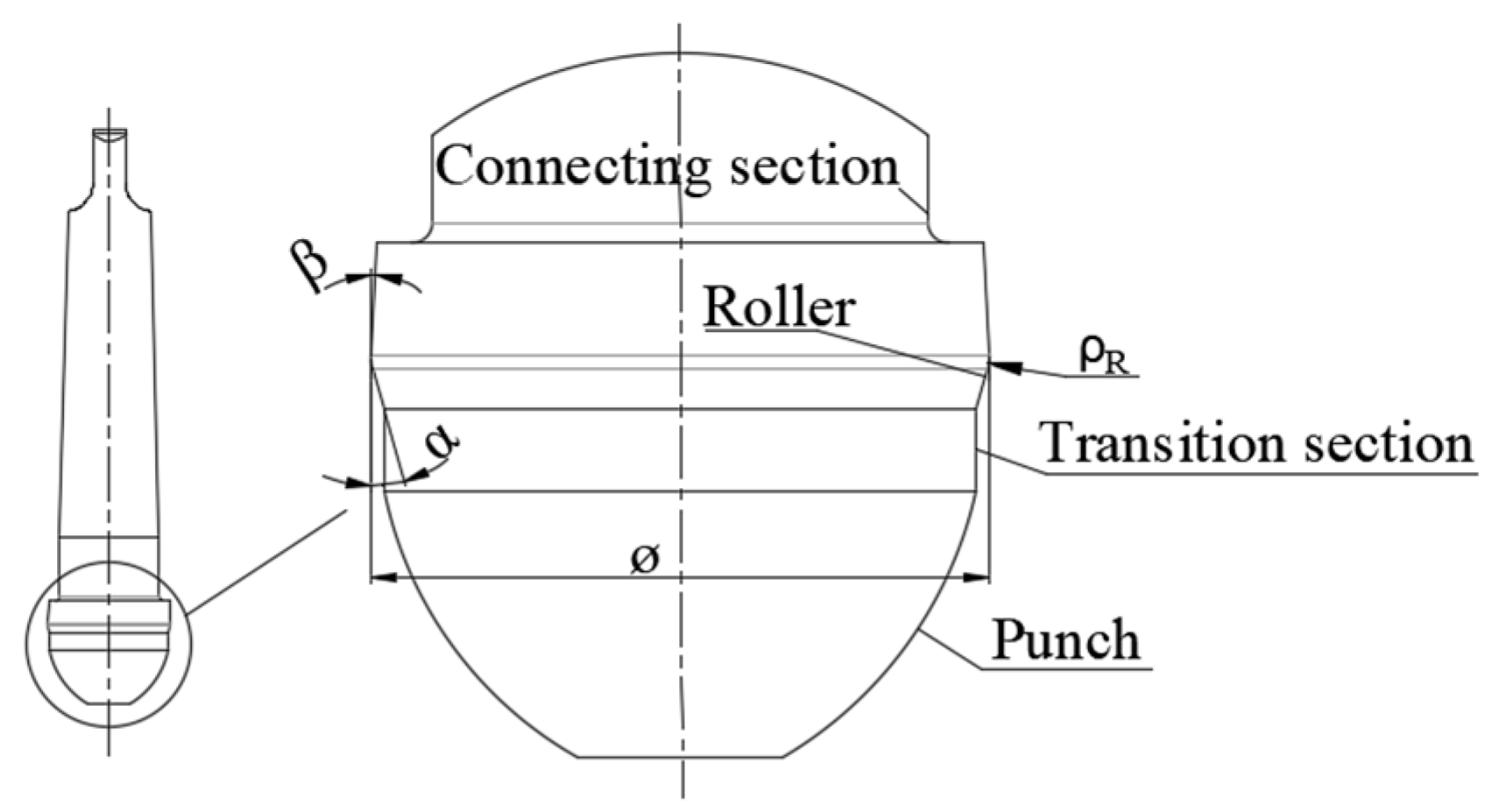
| Material | Forming Angle | Roller Fillet Radius | Exit Angle | Flange Diameter |
|---|---|---|---|---|
| Cr12MoV | 15° | 2–4 mm | 3° | 30 mm |
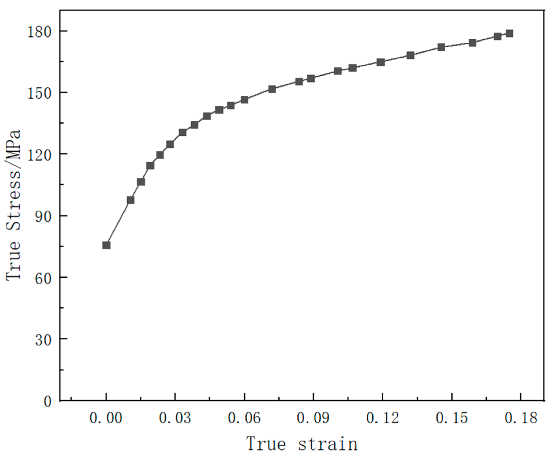
| Elastic Modulus E/MPa | Poisson’s Ratio μ | Density ρ/(kg·m−3) | Tensile Strength /MPa | Yield Strength /MPa | Elongation /% |
|---|---|---|---|---|---|
| 73,100 | 0.33 | 2840 | 179 | 75.8 | 18 |
Disclaimer/Publisher’s Note: The statements, opinions and data contained in all publications are solely those of the individual author(s) and contributor(s) and not of MDPI and/or the editor(s). MDPI and/or the editor(s) disclaim responsibility for any injury to people or property resulting from any ideas, methods, instructions or products referred to in the content. |
© 2023 by the authors. Licensee MDPI, Basel, Switzerland. This article is an open access article distributed under the terms and conditions of the Creative Commons Attribution (CC BY) license (https://creativecommons.org/licenses/by/4.0/).
Share and Cite
Zhu, L.; Huang, C.; Li, X.; Chang, X.; Liu, C. Two-Step Spin Forming of Thin-Walled Heads with Lateral Normal Flanged Holes. Metals 2023, 13, 1414. https://doi.org/10.3390/met13081414
Zhu L, Huang C, Li X, Chang X, Liu C. Two-Step Spin Forming of Thin-Walled Heads with Lateral Normal Flanged Holes. Metals. 2023; 13(8):1414. https://doi.org/10.3390/met13081414
Chicago/Turabian StyleZhu, Lijun, Cheng Huang, Xinhe Li, Xin Chang, and Chao Liu. 2023. "Two-Step Spin Forming of Thin-Walled Heads with Lateral Normal Flanged Holes" Metals 13, no. 8: 1414. https://doi.org/10.3390/met13081414
APA StyleZhu, L., Huang, C., Li, X., Chang, X., & Liu, C. (2023). Two-Step Spin Forming of Thin-Walled Heads with Lateral Normal Flanged Holes. Metals, 13(8), 1414. https://doi.org/10.3390/met13081414