Article

Improving Forging Outcomes of Cast Titanium Aluminide Alloy via Cyclic Induction Heat Treatment

Advanced Forming Research Centre, University of Strathclyde, 85 Inchinnan Drive, Inchinnan, Renfrew PA4 9LJ, UK
*
Author to whom correspondence should be addressed.
Metals 2023, 13(8), 1420; https://doi.org/10.3390/met13081420
Submission received: 29 June 2023 / Revised: 2 August 2023 / Accepted: 3 August 2023 / Published: 8 August 2023
(This article belongs to the Special Issue Microstructure and Properties of Intermetallics)

Abstract

:
The objective of this research was to improve the forging outcome of peritectic solidifying cast titanium aluminide (TiAl) 4822 alloy (Ti-48Al-2Nb-2Cr at.%) in hot isostatic pressed and homogenised (HH) condition using cyclic induction heat treatment (CHT). This study adds to research around CHT for TiAl alloys by applying industrially relevant induction heating to conduct five heating cycles at the single αphase temperatures (1370 °C) necessary for grain refinement. Two cooling rates were explored in each cycle, air cooling (ACCHT) and controlled furnace-like cooling (FCCHT), without returning to room temperature. Samples were assessed at each stage in terms of their morphologies, lamellar grain size and content, as well as phase and dynamic recrystallised fraction, and subsequent primary and secondary compression behaviour with uniaxial isothermal compression. The FCCHT process resulted in a homogeneously refined fully lamellar microstructure, and ACCHT, in a heterogeneous microstructure consisting of lamellar and feathery γ (γf) at differing fractions across the piece, depending on the cooling rate compared with HH. The results show that CHT improved forging outcomes for both compression stages investigated, resulting in uniform compression samples with higher volumes of dynamic recrystallised material compared with the instability seen with the compression of HH material.

1. Introduction

Titanium aluminides (TiAl) compare favourably to nickel-based superalloys in terms of their high elastic modulus and low density, and to titanium alloys in terms of high-temperature stability and oxidation resistance. This is particularly attractive when considering high-temperature applications as may be found in some automotive and aerospace engine components. The difficulty, as with most intermetallics, is in the processing and application of a material with an inherent brittle nature, arising from the long-range ordered phases present and large casting grain sizes. This leads to the wrought processing of cast TiAl material being largely avoided due to the high processing and equipment costs involved in working at elevated temperatures, which are necessary to achieve acceptable workability [1].
Peritectic TiAl alloys, such as as-cast 4822 (Ti-48Al-2Nb-2Cr at.%), solidify through the single α phase, as shown in the calculated phase diagram (CALPHAD) in Figure 1. Grain growth is unrestricted and rapid at high temperatures, with this problem being exaggerated by scaling up to ingot production [2]. With further cooling, the crystallographic relationship between long-range ordered α2 and γ follows a Blackburn orientation relationship to form a single lamellar colony from each α grain, due to the single set of basal planes in α matching that of γ (α → α + γ → α2 + γ) [3,4].
Prior to upsetting, hot isostatic pressing (HIP) and homogenisation (HMG; together referred to as HH) have been found to improve the forging outcomes of as-cast TiAl material. The former removes casting porosity, and the latter improves elemental homogeneity in peritectic solidifying titanium aluminides, with this improving material response to compression [5,6,7]. However, neither process refines the initial large grained lamellar microstructure derived from casting. This makes some alloys difficult to forge with multiple steps at industrially viable temperatures, i.e., up to 1150 °C, with TZM (titanium, zirconium, molybdenum alloy) dies [8,9].
The initial grain refinement of the HH microstructure is the aim of cyclic heat treatments (CHT) to reduce or avoid hot working altogether. Other authors have looked to CHT to achieve refined fully lamellar (RFL) microstructures; Wang et al., in particular, pursued the grain refinement of peritectic alloys of 1 mm lamellar colony size to ≤50 μm, with the aim of avoiding hot working [10,11,12]. They described the importance of several parameters of the CHT process, including prior α transus homogenisation and the effect of the cooling rate on microstructure formation. Phase and microstructural transformations at different cooling rates were reviewed in greater detail by Ramanujan [4].
The CHT process for 4822 alloy was further explored by Kościelna and Szkliniarz, with homogeneous grain refinement being their aim [13,14]. This was shown to be possible with five controlled cycles just above the α transus with a hold time limited to reaching temperature uniformity across the sample, found to be ideal, combined with furnace cooling (FC). The mechanism of grain refinement of fully lamellar γ + α2 microstructures heated to above α transus temperatures involves the γ laths from these lamellar grains dissolving in the α matrix to form γ precipitates. These precipitates only exist for short periods of time at these temperatures but prevent rapid α grain growth. The γ precipitates then act as nucleation sites for new lamellar grains upon cooling [13]. Inhomogeneous grain refinement is a possibility with faster cooling, which can lead to a larger grain size distribution and different morphologies forming, such as feathery γ.
In their work on feathery γ (γf) microstructures, Dey et al. found that γf morphologies could be produced with cooling rates ranging from air cooling (AC) to water quenching (WQ) [15]. They found that γf could be found in two forms depending on where it had originated on the prior α grain. Internal feathery γ packets (γf-int) are randomly misorientated γ laths that nucleate within prior α grains as the lamellar structure begins to form, without being in contact with any grain boundary. Grain boundary feathery γ packets (γf-gb) grow from the grain boundary of one lamellar grain into the adjacent lamellar grain, with no apparent orientation relationship with their host lamellar grain. The compression behaviour of these γf-dominant microstructures in TiAl alloys is not well documented and is investigated in the present work.
Other advances into multi-stage processing aimed at grain refinement in peritectic alloys are well documented [16,17,18]. However, the application of induction heating equipment to perform CHT, rather than direct electrical resistance equipment, and its subsequent effect on processing, rather than final material properties, are not aspects covered in the literature to the best of the authors’ knowledge. An aspect of this is whether there is any necessity of returning to room temperature (RT) after each cycle, or whether cycling from 800 °C, still in the same γ + α2 phase as RT, would cut down processing time and improve energy efficiency.
Successful primary compression, seen as equivalent to ingot breakdown or forming a pre-form in this study, seeks to generate homogeneously refined microstructures consisting of isotropic material with high lamellar globularisation and a large dynamic recrystallized fraction (X-DRX). To achieve this, pre-compression processing should aim to deliver a material that responds to deformation efficiently. As discussed by Gupta et al. and Fuchs on peritectic TiAl alloys, an efficient response, under constant compression conditions, depends on the state of the initial microstructure and its elemental homogeneity [8,19]. Forging trials on Ti-45Al alloy by Seetharaman and Semiatin found that the globularised fraction increased with a lower initial lamellar grain size, as also found by Fuchs in 4822 alloy, in turn increasing the X-DRX [20].
The CHT process could fulfil this purpose, and it has been shown to produce refined microstructures together with elemental homogeneity at a smaller scale; both are proven to promote the rate of globularisation of lamellar material and improve the X-DRX [20,21,22]. This could reduce the forging steps required to achieve the homogeneously refined microstructure required for secondary wrought processing techniques, such as hot rolling or isothermal closed-die forging.
In the present study, two cooling rates in each cycle of CHT, AC and FC, were applied as grain refining heat treatments compared with HH alone and anticipated to improve forging outcomes. This was assessed with microstructural characterisation to quantify remnant lamellar content and size, as well as X-DRX, and monitoring compression behaviour upon primary and secondary compression.

2. Materials and Methods

2.1. Sample Preparation

A cylindrical sample of Ø60 × 233 mm was machined using electrical discharge machining (EDM) from the centre of a cast plasma-arc melted 4822 ingot (Ti-47.2Al-1.83Nb-1.83Cr at. %) of Ø140 × 233 mm. This material was in fully lamellar condition, with grain sizes of around 1 mm. This sample was consolidated using hot isostatic pressing (HIP) for four hours at 1270 °C and 175 MPa under argon followed by natural cooling and then subjected to homogenisation (HMG) within the single α phase at 1380 °C for two hours under vacuum, again followed by natural cooling. This material, referred to as HIP and HMG (HH), respectively, was then cut into cylindrical compression samples of Ø13 × 20 mm using EDM. The composition data used for the CALPHAD in Figure 1 were determined using inductively coupled plasma (ICP) by the supplier and are shown in Table 1. From the CALPHAD and the literature, the target temperatures for cyclic heat treatments were identified.

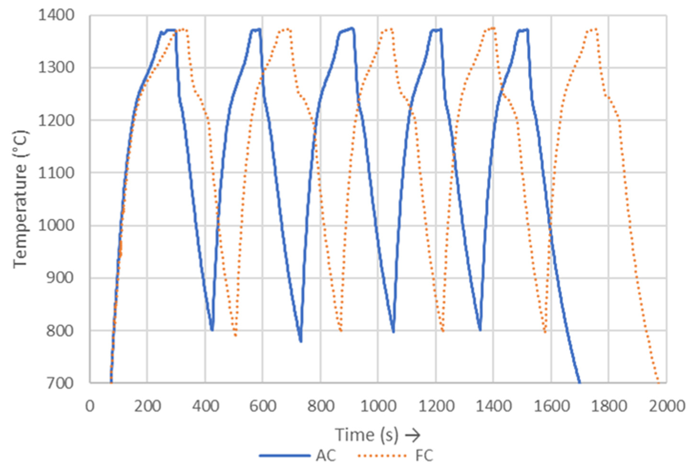
2.2. Cyclic Heat Treatment Conditions Using Induction Equipment

The cyclic heat treatments (CHT) on the 4822 alloy samples in HH condition were carried out using a 15 kW Ambrell EKOheat induction heating system in conjunction with an induction coil. The inductor and system electronics were water-cooled during the heat treatment using a recirculating chiller. The inductor consisted of a 6-turn copper coil with an internal diameter of 97 mm, working length of 95 mm, and wall thickness of 0.81 mm. The inductor was mounted within a refractory concrete enclosure with an empty tubular region of Ø 87 mm in its centre to position the sample. The settings for the induction heating control system were as follows:
  • Resonant frequency: ~93 kHz. Tap setting: 16.
  • Capacitance: series/parallel arrangement ((2 µF × 1 µF) − (2 µF × 1 µF) -> equivalent to 1 µF).
  • Starting voltage: approximately 550 V (decreased to ~350 V to prevent overshooting the target temperature at 1340 °C). The voltage settings for each sample varied due to differences in their thermal, electrical, and magnetic properties.
  • Temperature control was manually achieved by adjusting the induction voltage.
The temperature was monitored and recorded with a dual-wavelength SPOT pyrometer (AMETEK LandR160) capable of measuring temperatures between 550 and 1600 °C at the resolution of 0.1 °C, using ratio mode to minimise the impact of changing surface emissivity. The pyrometer beam (~few mm2) was focused on the surface to minimise temperature overshoot.
The target temperature–time profile is shown in Figure 2. Compression samples were coated with 87.2.207 glass lubricant from Prince Minerals to reduce oxidation. To start the CHT, samples were rapidly heated to 1370 °C from room temperature and held for 30 s before being cooled to 800 °C, where the cycle started again for five cycles. Furnace cooling and air cooling (FC, AC) were applied to achieve different pre-compression microstructures. FC was applied by reducing the power, to induce cooling until 1200 °C, followed by switching the power off. AC was applied by simply turning the power to the induction equipment off. These conditions are referred to as furnace-cooled cyclic heat treatment (FCCHT) and air-cooled cyclic heat treatment (ACCHT). Samples were held in an alumina jig within the induction coil for the repeatability of positioning, and this also provided the insulation required for the part to reach the target temperature.

2.3. Compression Testing

For primary compression, all cylindrical samples were coated with glass as above to reduce oxidation and were lubricated with boron nitride. All material was compressed to 50% at 1100 °C after a 5 min soak at this temperature at a strain rate of 0.001 s−1 using a Zwick Roell Z250 machine, followed by air cooling.
To assess for any continued effect of the CHT on the forging outcomes of this alloy, secondary compression samples of Ø6 × 9 mm were machined from primary compressed material using EDM along the same axis as compression. Secondary compression conditions followed the same procedure as the primary compression stage, i.e., 50% compression at 1100 °C, but at strain rates of 0.001, 0.01, and 0.1 s−1 to also establish the strain rate sensitivity (m) of the material.

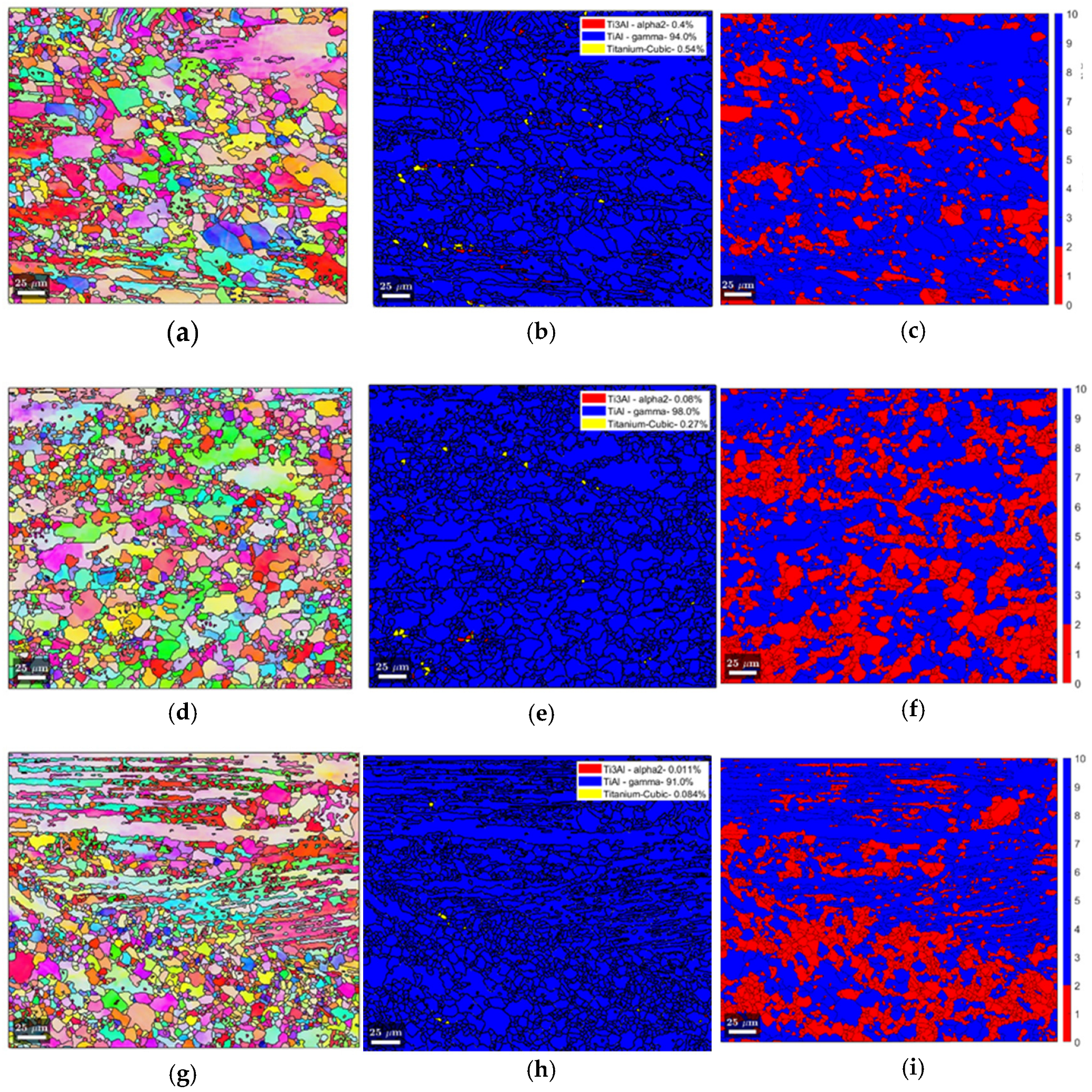
2.4. Microstructural Analysis

Following metallurgical preparation, the microstructural analysis of all pre-compression samples was focussed on the centre (C) and the faces of CHT material (F1 and F2). For post-compression samples, the centre (P1) and 1 mm from the lateral end were analysed (P2). For the microstructural analysis, a Leica optical microscope (OM) was used for all sites. Scanning electron microscopy (SEM) was performed using an FEI Quanta-250 with field-emission gun and back-scattered electron (BSE) detector at 15–20 kV at central sites. OM and BSE images were analysed with ImageJ software to determine microstructural parameters. Firstly, morphology volume fraction was estimated for lamellar, equiaxed, or feathery γ content (%) using the systematic manual point count method; ASTM E562-19e1. This was then applied to calculate lamellar grain size (μm) using the linear intercept method, ASTM E112-13, at 0° and 90° to compression. Nordlys Nano electron back-scatter diffraction (EBSD) equipment was set up with an acquisition time of 120 mS and 0.5 μm step size. This was used to identify grain boundaries, and 10° of misorientation was used to define a grain, as well as to assess the phase fraction using crystallographic mapping tools available in Aztec (Oxford Instruments). The dynamic recrystallised fraction (X-DRX) was determined using the grain orientation spread (GOS) approach. The GOS approach uses the average misorientation degree within grains; the misorientation spread in DRX grains is lower than that of deformed grains (approach identified by Hadadzadeh et al. [23]). This has been applied to work on TiAl alloys using ≤2° as the benchmark for recrystallised material, as was used here [24,25,26].

3. Results and Discussion

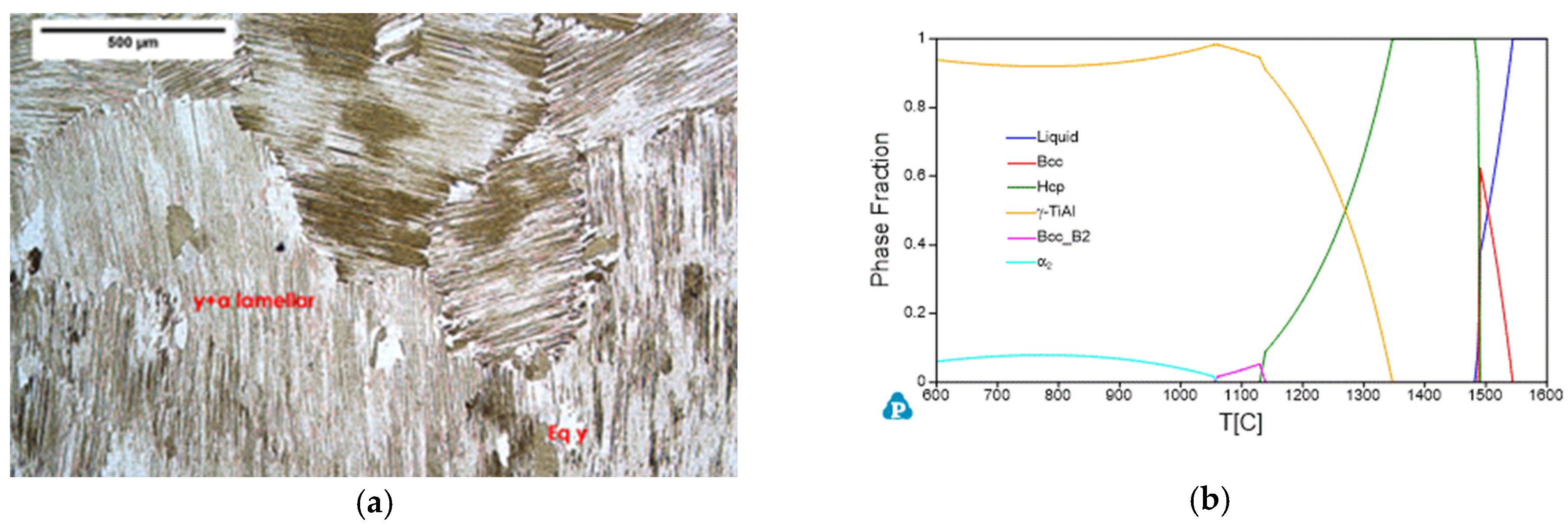
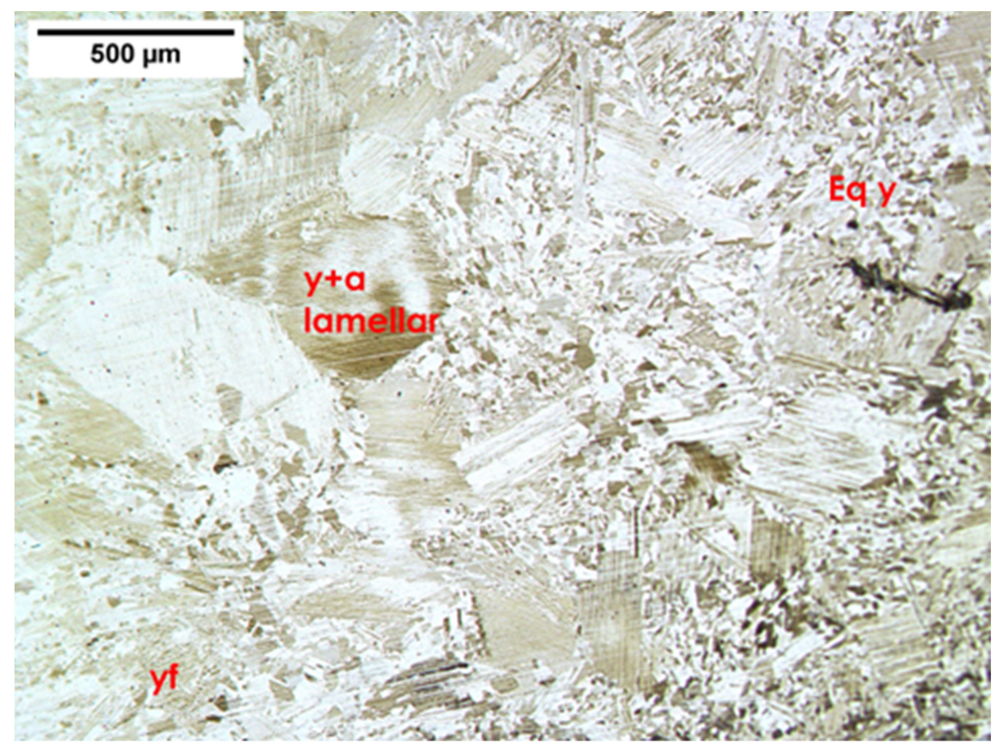
3.1. Initial Microstructure

A microstructural analysis was conducted on 4822 alloy in the three starting material conditions already discussed, HH, ACCHT, and FCCHT, to assess the influence of CHT on the microstructure. Using optical microscopy, lamellar grain dimensions as well as lamellar, feathery γ (γf), and equiaxed γ (γeq) fractions were determined.
The starting condition, HH, seen in Figure 1a, consisted of a largely fully lamellar (FL) microstructure, with 88.4% lamellar content and 11.6% γeq at the lamellar grain boundaries, with a large average lamellar grain size of 1060 μm and lath thickness of 0.92 μm. Microstructural characteristics from OM image processing in comparison to CHT material are detailed in Table 2.

3.2. Cyclic Heat Treatment Processing with Induction Equipment

The CHT process, shown by the temperature–time profile in Figure 3 obtained with pyrometer monitoring, shows the different temperature pathways for both air cooled (AC) and furnace cooled (FC) cyclic heat treatments (CHT). This was a manual process; hence, timings at ~1370 °C do differ between cycles, as do maximum temperatures between cycles. An automated system would be desirable for reproducibility but may prove difficult with the rapid heating and cooling rates seen in the process. Details of each cycle are shown in Table 3.
It was noted that there was a change in both heating and cooling rates seen at ~1250 °C upon heating, then cooling from 1250 to 1200 °C, in all cycles, with no change in voltage at this point. This would suggest there is a change in the thermophysical properties of the alloy within this range. This is likely the result of a phase transition. The examination of the CALPHAD in Figure 1b would suggest that the change from an α-dominant material to a γ-dominant one for cooling, and vice versa for heating, is the phase change involved.
With CHT, the homogeneity of microstructural change also needs considering because of the nature of induction heating, which tends to preferentially heat the outer layers of the material and rely on conduction to heat the inner areas (known as the skin effect).
The degree of the skin effect depends on the working frequency, electrical and magnetic properties of the sample, and the geometry/shape of the workpiece.
The skin or penetration depth (δ, in m) can be calculated using Equation (1):
δ = 503 ( ρ / ( µ r f ) )
where f is the induction heating frequency in Hz and ρ is the electrical resistivity of the 4822 alloy ( Ω m ) at that temperature [27]. μ r is the unitless relative magnetic permeability. For paramagnetic alloys, such as 4822, μ r is slightly >1 at room temperature, and μ r falls to unity with temperature, as such unity is used [28]. Based on this, δ for the 4822 alloy under the CHT conditions discussed was anticipated to be in the region of 1.9–2.5 mm.

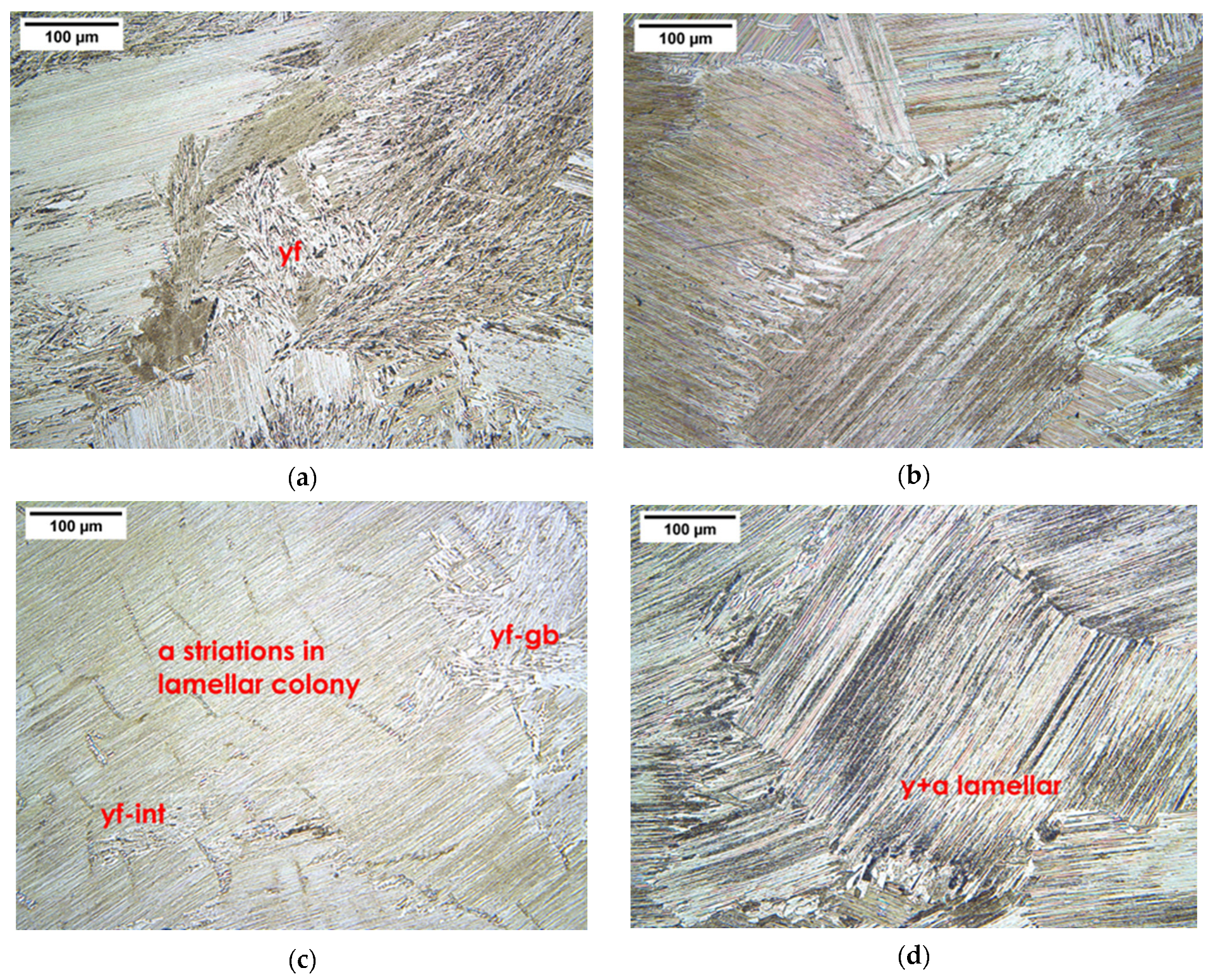
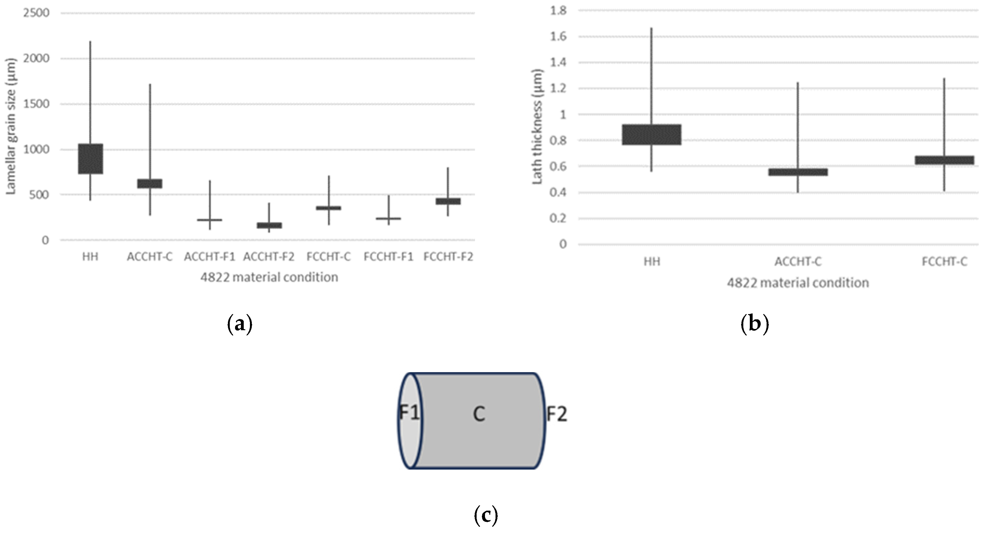
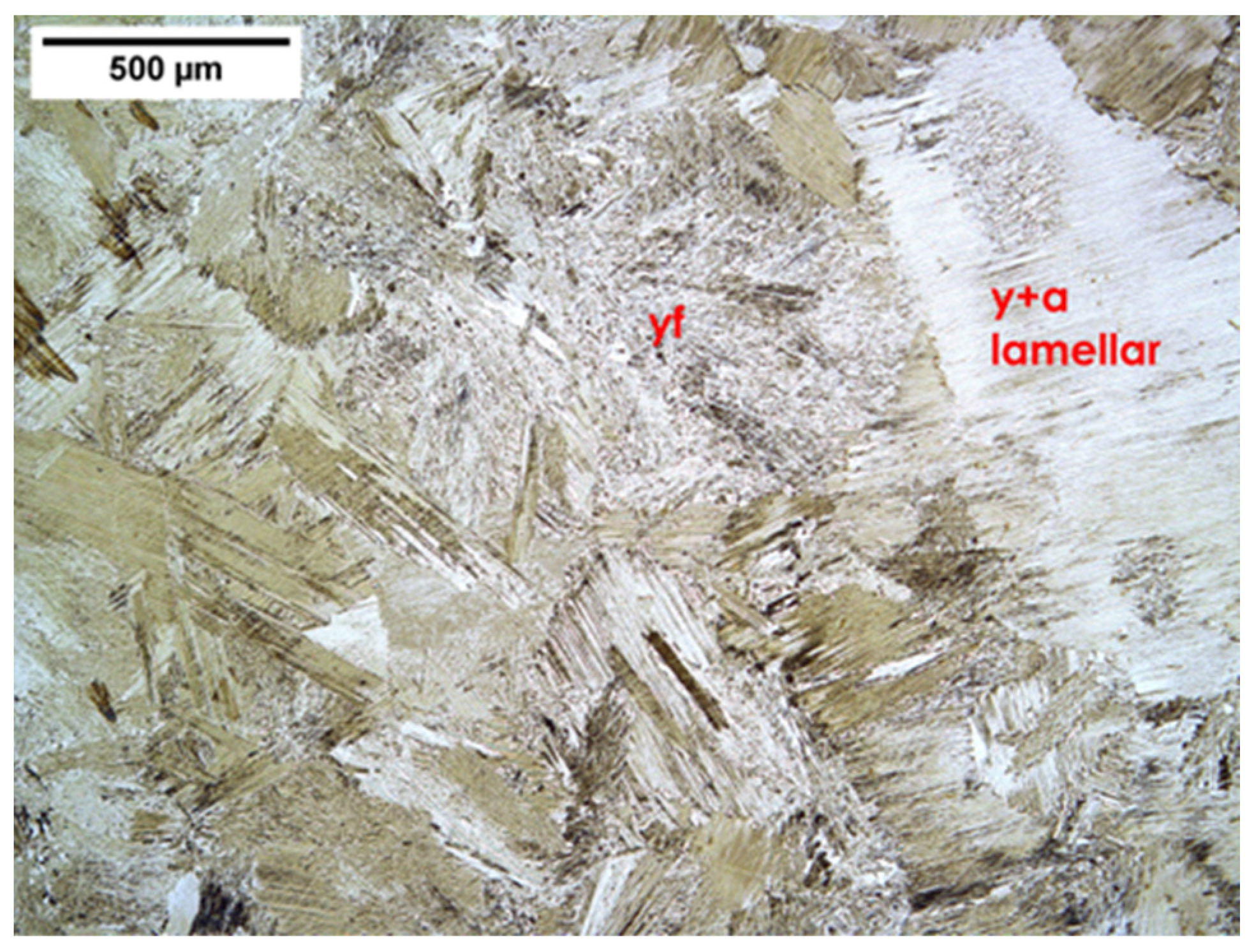
3.3. Cyclic Heat Treated Microstructures

Both ACCHT and FCCHT were analysed at three sites, the centre of the sample (C) and both faces (F1 and F2), as detailed in Table 2.
Both CHT sequences resulted in a microstructure lacking equiaxed material, consisting of refined lamellar grains and γf (Figure 4). With ACCHT, γf formed at both grain boundaries (γf-gb) and within lamellar grains (γf-int). The fraction of γf throughout the ACCHT sample being similar at the faces but the fraction swapping to being largely lamellar dominant at the centre of the sample, suggesting formation of γf, was dependent on the cooling rate. FCCHT showed a more homogeneous microstructure, with the lamellar fraction being dominant and γf being relatively constant in comparison and only present at the grain boundaries. The laths of the lamellar content in both FCCHT and ACCHT were finer in comparison to HH, with average lath thickness values of 0.58 μm and 0.68 μm in ACCHT and FCCHT, respectively. Post heat treatment analysis see Figure 5.
The extent of grain refinement identified by Wang et al., described in the introduction, was not seen in this study. This could be for several reasons, including that the CHT process does not return to RT but to 800 °C.
However, the average lamellar grain size was still reduced with both CHT sequences across the work piece as compared with HH material. Lamellar dimensions and morphology contributions were homogenous across the work piece with FCCHT, suggesting temperature uniformity in the FCCHT cycle, though this was not the case with ACCHT. The microstructures produced appeared heavily influenced by the cooling rate, as identified by Wang et al. The FCCHT process led to less γf forming, with no γf in FCCHT material being in a γf-gb form. Lamellar colonies were the dominant morphology across FCCHT material. FCCHT material could be described as a refined fully lamellar (RFL) microstructure, much sought after for final material properties of toughness and ductility, where the fine grain size of the fully lamellar microstructure resists crack initiation and growth [29,30,31].
With ACCHT, the microstructure was more heterogeneous in comparison to HH or FCCHT, with differences in the morphology fraction across the workpiece, consisting of γ + α2 colonies and γf. The γf present in ACCHT was in both forms, γf-gb and γf-int, with γf-int being apparent at F1 and F2, and this appearing to nucleate at the centre of lamellar grains in ACCHT material. This is in agreement with the findings obtained by Dey et al. regarding the γf form being dependent on the cooling rate [15].
This suggests that the temperature across the piece was not uniform. The temperature oscillations with each cycle are dampened at the centre, with the temperature not reaching the α phase [13,14]. Two other observations support this theory. The striations of α seen in the OM image in Figure 4c, all in the same direction, would suggest that the α phase had begun to grow into the γ laths of the γ + α lamellar grain, but the dominant γ laths cannot be described as a precipitate so do not nucleate new grains upon cooling [13]. Additionally, uniform lamellar grain refinement is only enabled by the combination of sufficient time in the α phase to dissolve γ to form a precipitate and a slower/less sudden cooling of FCCHT, to allow the lamellar morphology to form [18]. This was an issue anticipated with AC but one that could be mitigated with the further refinement and modelling of the thermal cycle. As δ is anticipated to be in the region of 1.9–2.5 mm depth for this alloy, this leads to a more uniform temperature across the workpiece compared with, say, CHT for steels; the skin effect is unlikely to hinder further development of the cycle at this scale [28].

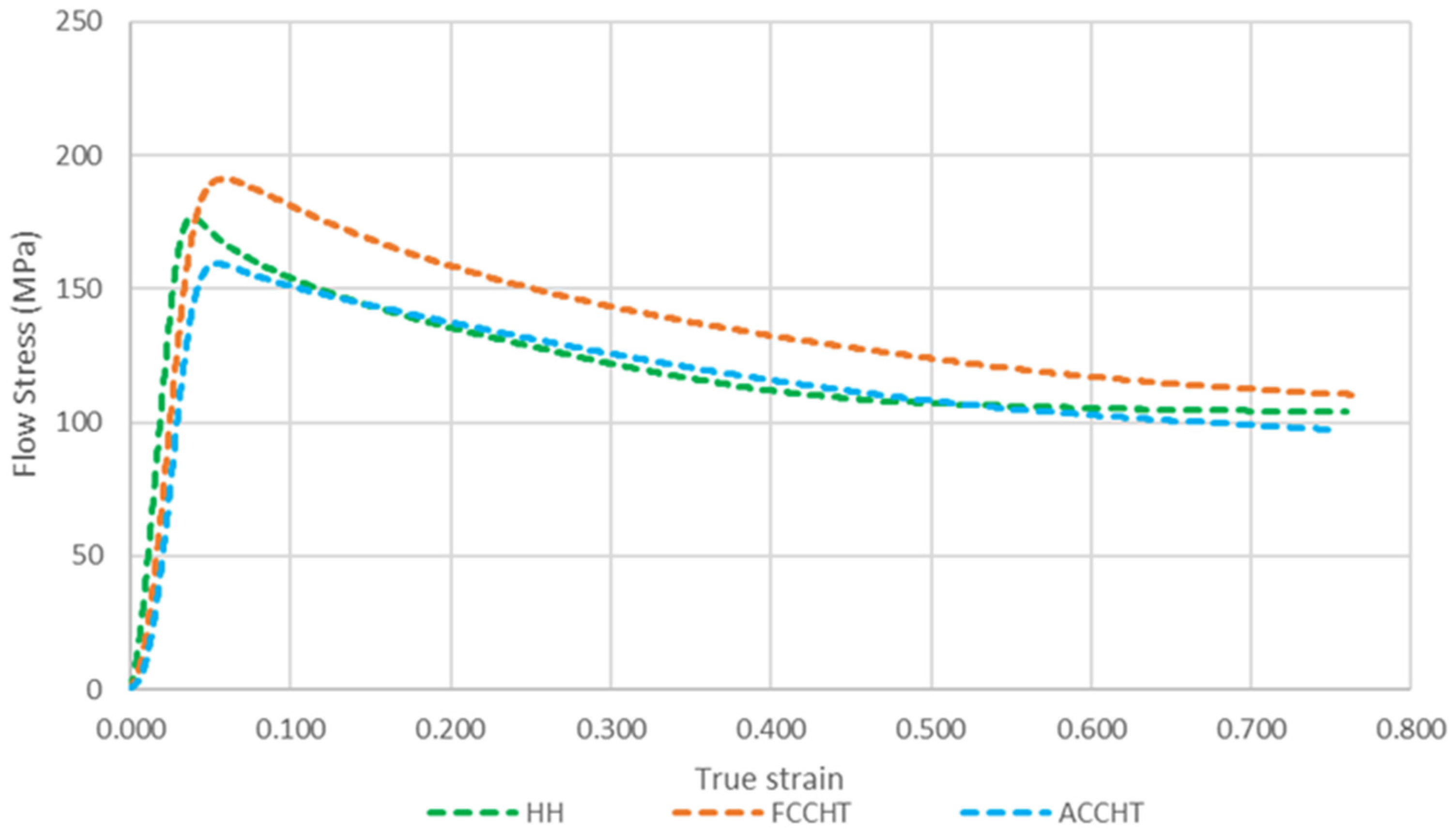
3.4. Primary Compression Behaviour

Each stress–strain curve, shown in Figure 6, follows a similar pattern for each 4822 condition; several processes are active with a degree of initial work hardening, likely due to the rapid dislocation pile-ups in the γ laths slowed by critical strain (εc) being reached. This is followed by high stored energy in the fragmented lamellar material initiating a rapid DRX, hence the relatively sharp peaks seen here. The peak flow stress (σpfs) is followed by subsequent flow softening. This can be explained by several processes. Compression of fully lamellar material leads to the fragmentation and kinking of these morphologies. With strain and time, the DRX proceeds, leading to further softening, as reviewed by Seetharaman and Semiatin [20]. Recrystallisation and, to a lesser extent, phase-boundary bulging was identified as the mechanisms of globularisation by Zhang et al.; this behaviour was further described by Tian et al. [32,33].
The differences in the flow curves of the three material conditions, the values of σpfs and εc, and the subsequent softening are due to the initial microstructure and potential to either orientate or globularise the lamellar content. FCCHT showed the highest value of σpfs, likely due to a fine fully lamellar microstructure, and ACCHT showed the lowest σpfs, probably due to low lamellar content and the lowest grain size. All CHT material moved towards stable material flow under these compression conditions; HH material, on the other hand, exhibited non-uniform deformation (see Table 4), with the highest rate of strain hardening, the earliest εc, and relatively sharp σpfs characterising its flow behaviour.
Table 4 illustrates the samples after deformation, with HH material showing evidence of localised shear. As geometry, die, lubrication, and compression conditions were the same across the three tests, this is a sign of flow localisation caused by the large grained fully lamellar microstructure [34,35,36].

3.4.1. Behaviour of γf under Compression Conditions

With heating to the compression temperature and soaking for 5 min (1100 °C, high γ + α2), the packets of γf present in ACCHT material, present as both γf-int and γf-gb forms, largely transformed to fine γeq grains, as shown by comparing Figure 7 and Figure 8, with microstructural characteristics summarised in Table 5.
The γf → γeq transformation was exploited in non-wrought grain refinement processing by Yim et al. and Hu and Yang et al. by applying annealing heat treatment at the high end of the γ + α phase region [17,37]. The γf → γeq transformation is due to the inherent instability of the γf microstructure from its initial formation. Dey et al. identified the initial packets of γf as being chemically unstable, with higher localised strain compared with prior lamellar morphologies, which subsequently drives the transformation into globular morphologies, almost to completion, as seen here [15]. The high γeq content and lack of lamellar morphologies to globularise at the outer 1 mm of the workpiece could have contributed to the low σpfs seen under compression.

3.5. Primary Compression Microstructures

As Figure 9 shows, each material resulted in a microstructure still containing lamellar morphologies after primary compression. Recrystallised and deformed material can be seen to surround the large remnant lamellar grains, as seen in Figure 10a,d,g orientation maps, with lamellar regions having similar crystallographic orientation through the grain. The distribution of recrystallised grains is illustrated with X-DRX mapping in Figure 10c,f,i. The content and details of the remnant morphologies are shown in Table 6.

3.5.1. Primary Compression: HIP and Homogenised Microstructure

HH material showed the highest lamellar grain sizes in this study; this resulted in non-uniform deformation and flow localisation caused by the large grained fully lamellar microstructure [34,35,36]. Flow localisation then led to poor conditions for globularisation, with the post-compression HH material resulting in the highest lamellar content and size values at both P1 and P2.

3.5.2. Primary Compression: ACCHT Microstructure

ACCHT resulted in the highest X-DRX fraction at both P1 and P2, 44.7% and 54.6%, respectively, together with the lowest overall lamellar content, 29.2% at P1 and 15.7% at P2, with these lamellar structures being of the smallest grain size, as shown in Figure 11a. HH material showed the highest lamellar content at P1, 44.4%, with the largest spread of lamellar grain size and the lowest X-DRX fraction, 22.6%. The X-DRX was calculated using the grain orientation spread (GOS) approach, and an example is shown in Figure 12. Following this method, ≤2° spread within the grain was deemed to have been recrystallised; above this, it was considered deformed.
The X-DRX tends to be dependent on the initial lamellar colony size; this is due to grain boundaries acting as nucleation sites for globular morphologies, with high lamellar–lamellar grain boundary density being preferred for globularisation [20]. Semiatin, Seetharaman, and Weiss reviewed earlier work looking at the relationship between the starting microstructure, flow softening rate, recrystallisation, and flow localisation [36]. The authors identified that the lamellar characteristics, especially lamellar grain sizes, were the most significant factor influencing the flow stress, with Semiatin, Seetharaman, and Ghosh identifying the effect that grain size and strain rate have on the globularised fraction [35]. Another factor in the X-DRX and the globularised fraction is the heterogeneous strain distribution across the work piece [38]. This is shown by the microstructural analysis of lamellar content at P1 and P2 (Table 6). Interestingly, this difference across the workpiece was reduced with ACCHT, perhaps due to the lack of lamellar content at P2 post-CHT, as discussed below.
As already discussed in Section 3.4.1, the γf present in ACCHT material should have transformed to γeq upon heating to the compression temperature; however, it was still relatively heterogeneous, with lamellar morphologies being present to differing degrees depending on the cooling seen across the sample (see Table 5). Given that lamellar–lamellar grain boundaries support globularisation, the heterogeneous microstructure at the sample faces does not appear to be detrimental to the microstructural outcome, resulting in a comparably homogeneous microstructure across P1 and P2 with the lowest remnant lamellar size and content, together with the highest X-DRX, which was the highest at P2.
The higher X-DRX at P2 for ACCHT material is unusual and likely due to the large volumes of γeq present at the periphery of ACCHT material (F1 and F2) (Figure 7) compared with FCCHT and HH.

3.5.3. Primary Compression: FCCHT Microstructure

The homogenously refined fully lamellar microstructure of FCCHT material resulted in a larger X-DRX compared with HH at P1, as well as smaller remnant lamellar colonies at P1 and P2. The higher X-DRX values are due to the initial higher grain boundary density compared with HH, as discussed above. However, there are similar post compression lamellar content values between FCCHT and HH; see Table 6. The fine-lath lamellar content of pre-compression FCCHT material may explain the lack of globularisation at P1 and P2 seen under compression. Like larger lamellar grain sizes, fine lamellar morphologies are also detrimental to globularisation kinetics [32,39].

3.6. Secondary Compression Behaviour

The secondary compression stress–strain curves in Figure 13a show that a profile similar to that of primary compression was followed, i.e., strain hardening to peak flow stress followed by flow softening. The peak flow stresses increase with the strain rate for each material. At a strain rate of 0.001 s−1, all material moved towards near steady-state flow stress between 90 and 100 MPa with the increase in strain during secondary compression. ACCHT material showed the lowest steady-state stress; it is assumed that the steady-state condition would correspond to a quasi-stable microstructure being achieved [40]. This was not achieved at faster strain rates.
From Figure 13b and Table 7, HH and ACCHT show the same m value, 0.25, with FCCHT showing the lowest ε0.1 in secondary compression, 0.24. Flow localisation and shear of the HH samples is visible again. This is likely to be due to the HH primary compressed material containing the largest remnant lamellar grains as well as the lowest X-DRX. For these reasons, the m value of 0.25 for HH should not be taken as a true representation of its strain rate sensitivity.
FCCHT material shows the highest secondary σpfs at slow strain rates and the lowest m; this may be due to the primary compressed FCCHT material consisting of larger lamellar grain size and finer laths than ACCHT at both P1 and P2 [32,39].
Secondary compression of ACCHT material shows the lowest σpfs at all strain rates and an m value of 0.25 but with successful uniformly compressed samples. It is anticipated that m is being restrained here by the compression temperature rather than any remnant microstructural morphology. It is likely that only the compression of this alloy at higher temperatures would increase m; this was generally found in Fuchs’ work and was due to the nucleation and growth of dynamic recrystallised grains being temperature-driven, easing dislocation destruction [25].

3.7. Secondary Compression Microstructures

The X-DRX maps calculated using the grain orientation spread (GOS) approach, illustrated in Figure 14c,f,i, show that ACCHT resulted in the highest X-DRX fraction at 66.1%, at a strain rate of 0.001 s−1, together with zero lamellar content. At the same strain rate, FCCHT material was also lamellar-free, with a 58.2% X-DRX. HH material gave the highest lamellar content, 7.2%, and the smallest X-DRX fraction, 47.2%.
All material tested resulted in average lamellar grain sizes below the 80 μm value suggested by Zhang et al. for facilitating further processing [32,39,41]. However, without CHT, remnant lamellar content was still present at each strain rate; the resulting X-DRX was lower at the slowest strain rate, and the presence of adiabatic shear was also clear at the fastest strain rate, as shown in Table 8 and Figure 15, respectively.
To produce a microstructure with a large X-DRX and low lamellar content, homogeneous compression is clearly first required. From the present results, it would appear that faster strain rates may be deleterious. Adiabatic shearing is present in HH at 0.1 s−1, and this appears to be absent with secondary compression of CHT material but cannot be dismissed as a possibility with the large remnant lamellar grain structures derived from primary compression [42]. Considering the obvious bulging in the compression samples in Table 7, it would suggest that adiabatic shear or flow localisation occurred under all material conditions other than at a strain rate of 0.001 s−1. Adiabatic shear and flow localisation may explain the lack of any trend between strain rate and resulting globularisation/X-DRX.

3.8. Summary of the CHT Process in Respect of Forging

The prospect of using the CHT process as a replacement for wrought processing seems improbable based on the results of the present research, but it is likely that CHT could be applied as a complementary technology to improve forging outcomes. The considerable impact of the cooling rate on the microstructure formed under CHT, with large differences in microstructure (e.g., lamellar grain size at the centre of samples at cooling rates of FCCHT, 369.3 μm, and ACCHT, 760.6 μm, with both cooling rates being under 10 °Cs−1), should be considered in process design.
Nonetheless, the CHT process investigated here took as-cast 4822 material in an unforgeable condition and made it forgeable at 1100 °C and 0.001 s−1, with initial grain refinement, as seen in FCCHT, or by largely removing lamellar morphologies, as with ACCHT. As seen with secondary compression at a strain rate of 0.001 s−1, CHT material is free of anisotropy inducing lamellar morphologies; this could result in a more isotropic material ready to benefit from secondary processing techniques, such as hot rolling or closed-die isothermal forging. The CHT process could, therefore, be considered as another complementary technology to improve forging efficiency and potentially reduce the number of wrought processing steps required for initial ingot breakdown [35,43,44,45].

4. Conclusions

This research set out to examine the possibility of improving the forging outcome of cast 4822 alloy by applying cyclic induction heat treatment. The following conclusions regarding 4822 alloy in HH and CHT conditions are drawn:
  • Hot isostatic pressing and homogenisation (HH) are clearly essential processing steps but does not result in a material best placed for successful compression, with lamellar grain sizes averaging >1000 μm and low lamellar–lamellar grain boundary density restricting the globularisation of lamellar content.
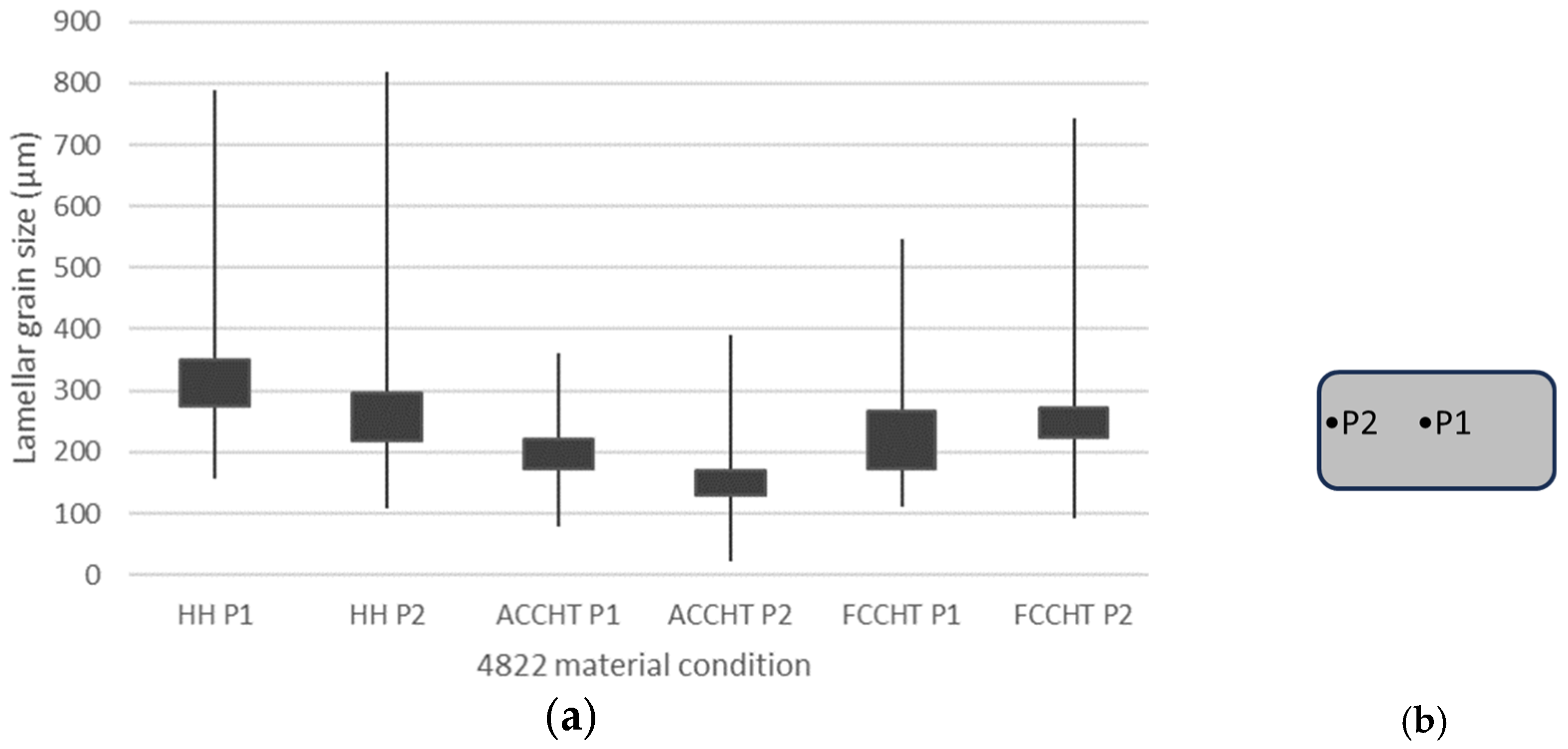
  • Cyclic induction heat treatment (CHT) can provide lamellar grain refinement compared with HH at a controlled furnace cooling rate (FCCHT). FCCHT results in a homogeneously refined fully lamellar microstructure with average lamellar grain size of 369.3 μm at the centre of the work piece. This grain refinement leads to successful primary compression.
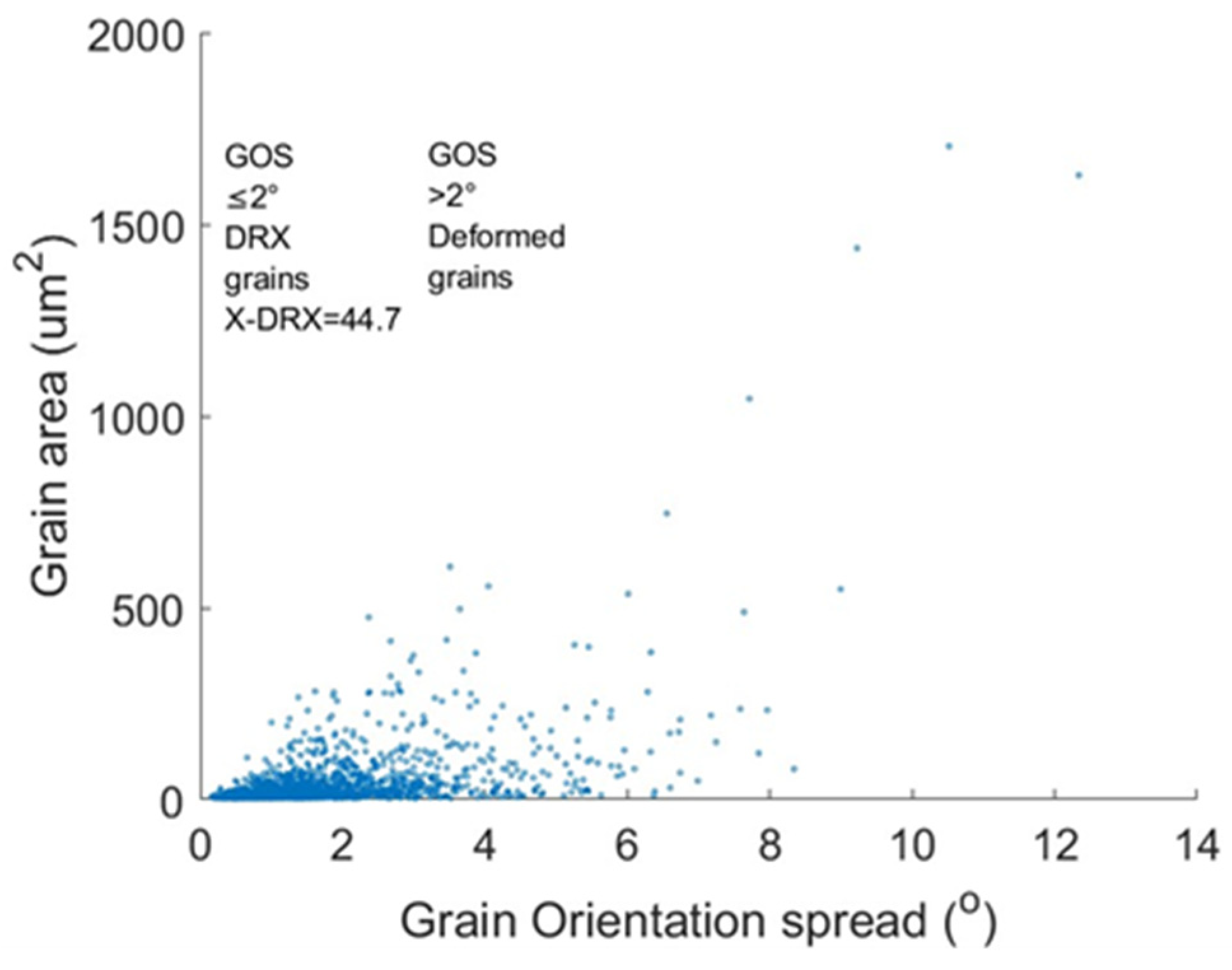
  • The heterogeneous microstructure under ACCHT, consisting of differing quantities of α2 + γ lamellar grains and γf across the work piece, does not appear to hinder primary or secondary compression under these conditions or at this scale, resulting in the highest dynamic recrystallised fraction values in both compression stages, 54.6% and 66.1%, respectively.
  • The dominant γf in the ACCHT process transforms to γeq upon re-heating within the high γ + α2 phase region, i.e., during primary compression at 1100 °C.
  • CHT material after secondary compression at a strain rate of 0.001 s−1 is free of anisotropy inducing lamellar morphologies; this material should be considered for secondary processing techniques such as hot rolling or closed-die isothermal forging.

Author Contributions

S.P.: Conceptualization; Methodology; Investigation; Data curation; Writing—original draft preparation. A.A.: Methodology; Investigation; Writing—reviewing and editing. M.P.: Conceptualization and Supervision. P.B.: Supervision; Funding acquisition; and Writing—reviewing and editing. All authors have read and agreed to the published version of the manuscript.

Funding

The authors would like to acknowledge the funding provided by the Core membership at the Advanced Forming Research Centre (AFRC) and Scottish Research Partnership in Engineering (SRPe).

Data Availability Statement

The data presented in this study are available on request from the corresponding author. The data are not publicly available due to ongoing research.

Acknowledgments

We would also like to thank the Henry Royce Institute for their technical support and equipment through their Student Equipment Access Scheme.

Conflicts of Interest

The authors declare no conflict of interest.

References

  1. Appel, F.J.; Paul, J.D.; Oehring, M. Gamma Titanium Aluminides; Wiley-VCH: Weinheim, Germany, 2011; ISBN 978-3-527-63622-8. [Google Scholar]
  2. Larsen, D.E. Status of Investment Cast Gamma Titanium Aluminides in the USA. Mater. Sci. Eng. A 1996, 213, 128–133. [Google Scholar] [CrossRef]
  3. Denquin, A.; Naka, S. Phase Transformation Mechanisms Involved in Two-Phase TiAl-Based Alloys—I. Lamellar Structure Formation. Acta Mater. 1996, 44, 343–352. [Google Scholar] [CrossRef]
  4. Ramanujan, R.V. Phase Transformations in γ Based Titanium Aluminides. Int. Mater. Rev. 2000, 45, 217–240. [Google Scholar] [CrossRef]
  5. Imayev, R.M.; Imayev, V.M.; Oehring, M.; Appel, F. Alloy Design Concepts for Refined Gamma Titanium Aluminide Based Alloys. Intermetallics 2007, 15, 451–460. [Google Scholar] [CrossRef]
  6. Zhang, D.; Dehm, G.; Clemens, H. Effect of Heat-Treatments and Hot-Isostatic Pressing on Phase Transformation and Microstructure in a β/B2 Containing γ-TiAl Based Alloy. Scr. Mater. 2000, 42, 1065–1070. [Google Scholar] [CrossRef]
  7. Kremmer, S.; Chladil, H.; Clemens, H.; Otto, A.; Güther, V. Near Conventional Forging of Titanium Aluminides. In Ti-2007 Science and Technology; The Japan Institute of Metals: Sendai, Japan, 2008; pp. 989–992. [Google Scholar]
  8. Fuchs, G.E. The Effect of Processing on the Hot Workability of Ti-48Al-2Nb-2Cr Alloys. Metall. Mater. Trans. A Phys. Metall. Mater. Sci. 1997, 28, 2543–2553. [Google Scholar] [CrossRef]
  9. Semiatin, S.L.; Seetharaman, V.; Jain, V.K. Microstructure Development during Conventional and Isothermal Hot Forging of a Near-Gamma Titanium Aluminide. Metall. Mater. Trans. A 1994, 25, 2753–2768. [Google Scholar] [CrossRef]
  10. Wang, J.N.; Xie, K. Refining of Coarse Lamellar Microstructure of TiAl Alloys by Rapid Heat Treatment. Intermetallics 2000, 8, 545–548. [Google Scholar] [CrossRef]
  11. Wang, J.N.; Yang, J.; Xia, Q.; Wang, Y. On the Grain Size Refinement of TiAl Alloys by Cyclic Heat Treatment. Mater. Sci. Eng. A 2002, 329–331, 118–123. [Google Scholar] [CrossRef]
  12. Yang, J.; Wang, J.N.; Wang, Y.; Xia, Q. Refining Grain Size of a TiAl Alloy by Cyclic Heat Treatment through Discontinuous Coarsening. Intermetallics 2003, 11, 971–974. [Google Scholar] [CrossRef]
  13. Szkliniarz, A. Grain Refinement of Ti-48Al-2Cr-2Nb Alloy by Heat Treatment Method. Solid State Phenom. 2012, 191, 221–234. [Google Scholar] [CrossRef]
  14. Kościelna, A.; Szkliniarz, W. Effect of Cyclic Heat Treatment Parameters on the Grain Refinement of Ti–48Al–2Cr–2Nb Alloy. Mater. Charact. 2009, 60, 1158–1162. [Google Scholar] [CrossRef]
  15. Dey, S.R.; Bouzy, E.; Hazotte, A. Features of Feathery γ Structure in a Near-γ TiAl Alloy. Acta Mater. 2008, 56, 2051–2062. [Google Scholar] [CrossRef]
  16. Kamyshnykova, K.; Lapin, J. Grain Refinement of Cast Peritectic TiAl-Based Alloy by Solid-State Phase Transformations. Kov. Mater. 2018, 56, 277–287. [Google Scholar] [CrossRef] [Green Version]
  17. Yim, S.; Bian, H.; Aoyagi, K.; Chiba, A. Effect of Multi-Stage Heat Treatment on Mechanical Properties and Microstructure Transformation of Ti-48Al-2Cr-2Nb Alloy. Mater. Sci. Eng. A 2021, 816, 141321. [Google Scholar] [CrossRef]
  18. Kim, J.K.; Kim, J.H.; Kim, J.Y.; Park, S.H.; Kim, S.W.; Oh, M.H.; Kim, S.E. Producing Fine Fully Lamellar Microstructure for Cast γ-TiAl without Hot Working. Intermetallics 2020, 120, 106728. [Google Scholar] [CrossRef]
  19. Gupta, R.K.; Narayana Murty, S.V.S.; Pant, B.; Agarwala, V.; Sinha, P.P. Hot Workability of Γ + α2 Titanium Aluminide: Development of Processing Map and Constitutive Equations. Mater. Sci. Eng. A 2012, 551, 169–186. [Google Scholar] [CrossRef]
  20. Seetharaman, V.; Semiatin, S.L. Effect of the Lamellar Grain Size on Plastic Flow Behavior and Microstructure Evolution during Hot Working of a Gamma Titanium Aluminide Alloy. Metall. Mater. Trans. A Phys. Metall. Mater. Sci. 2002, 33, 3817–3830. [Google Scholar] [CrossRef]
  21. Nobuki, M.; Tsujimoto, T. Influene of Alloy Compostion on Hot Deformation Properties of TIAl Intermetallics. ISIJ Int. 1991, 31, 931–937. [Google Scholar] [CrossRef] [Green Version]
  22. Semiatin, S.L.; Seetharaman, V.; Weiss, I. Flow Behavior and Globularization Kinetics during Hot Working of Ti-6Al-4V with a Colony Alpha Microstructure. Mater. Sci. Eng. A 1999, 263, 257–271. [Google Scholar] [CrossRef]
  23. Hadadzadeh, A.; Mokdad, F.; Wells, M.A.; Chen, D.L. A New Grain Orientation Spread Approach to Analyze the Dynamic Recrystallization Behavior of a Cast-Homogenized Mg-Zn-Zr Alloy Using Electron Backscattered Diffraction. Mater. Sci. Eng. A 2018, 709, 285–289. [Google Scholar] [CrossRef]
  24. Chen, X.; Tang, B.; Liu, D.; Wei, B.; Zhu, L.; Liu, R.; Kou, H.; Li, J. Dynamic Recrystallization and Hot Processing Map of Ti-48Al-2Cr-2Nb Alloy during the Hot Deformation. Mater. Charact. 2021, 179, 111332. [Google Scholar] [CrossRef]
  25. Wan, Z.; Sun, Y.; Hu, L.; Yu, H. Dynamic Softening Behavior and Microstructural Characterization of TiAl-Based Alloy during Hot Deformation. Mater. Charact. 2017, 130, 25–32. [Google Scholar] [CrossRef]
  26. Li, J.; Li, M.; Hu, L.; Shi, L.; Xiao, S.; Chen, Y.; Zhou, T. Dynamic Recrystallization, Phase Transformation and Deformation Mechanisms of a Novel Ti-43Al-6Nb-1Mo-1Cr Alloy during the Isothermal Deformation. Mater. Charact. 2023, 199, 112789. [Google Scholar] [CrossRef]
  27. Fecht, H.-J.; Mohr, M. Metallurgy in Space The Minerals, Metals & Materials Series; Springer: Cham, Switzerland, 2022; ISBN 9783030897840. [Google Scholar]
  28. Rudnev, V.; Loveless, D.; Cook, R.L. Handbook of Induction Heating, 2nd ed.; CRC Press: Boca Raton, FL, USA, 2017; ISBN 9781466553972. [Google Scholar]
  29. Kim, Y.-W.; Sang Lan, K. Advances in Gammalloy Materials–Processes–Application Technology: Successes, Dilemmas, and Future. JOM 2018, 70, 553–560. [Google Scholar] [CrossRef] [Green Version]
  30. Chen, Y.Y.; Li, B.H.; Kong, F.T. Microstructural Refinement and Mechanical Properties of Y-Bearing TiAl Alloys. J. Alloys Compd. 2008, 457, 265–269. [Google Scholar] [CrossRef]
  31. Liu, C.T.; Schneibel, J.H.; Maziasz, P.J.; Wright, J.L.; Easton, D.S. Tensile Properties and Fracture Toughness of TiAl Alloys with Controlled Microstructures. Intermetallics 1996, 4, 429–440. [Google Scholar] [CrossRef]
  32. Zhang, W.J.; Lorenz, U.; Appel, F. Recovery, Recrystallization and Phase Transformations during Thermomechanical Processing and Treatment of TiAl-Based Alloys. Acta Mater. 2000, 48, 2803–2813. [Google Scholar] [CrossRef]
  33. Tian, S.; Jiang, H.; Guo, W.; Zhang, G.; Zeng, S. Hot Deformation and Dynamic Recrystallization Behavior of TiAl-Based Alloy. Intermetallics 2019, 112, 106521. [Google Scholar] [CrossRef]
  34. Bibhanshu, N.; Bhattacharjee, A.; Suwas, S. Influence of Temperature and Strain Rate on Microstructural Evolution During Hot Compression of Ti-45Al-XNb-0.2C-0.2B Titanium Aluminide Alloys. JOM 2019, 71, 3552–3564. [Google Scholar] [CrossRef]
  35. Semiatin, S.L.; Seetharaman, V.; Ghosh, A.K. Plastic Flow, Microstructure Evolution, and Defect Formation during Primary Hot Working of Titanium and Titanium Aluminide Alloys with Lamellar Colony Microstructures. Philos. Trans. R. Soc. A Math. Phys. Eng. Sci. 1999, 357, 1487–1512. [Google Scholar] [CrossRef]
  36. Semiatin, S.L.; Seetharaman, V.; Weiss, I. Hot Workability of Titanium and Titanium Aluminide Alloys—An Overview. Mater. Sci. Eng. A 1998, 243, 1–24. [Google Scholar] [CrossRef]
  37. Hu, R.; Wu, Y.; Yang, J.; Gao, Z.; Li, J. Phase Transformation Pathway and Microstructural Refinement by Feathery Transformation of Ru-Containing γ-TiAl Alloy. J. Mater. Res. Technol. 2022, 18, 5290–5300. [Google Scholar] [CrossRef]
  38. Chen, X.; Tang, B.; Chen, W.; Yang, Y.; Zheng, G.; Fan, Z.; Li, J. Effect of Inter-Pass Annealing on the Deformation Microstructure of Ti-48Al-2Cr-2Nb Alloy. J. Alloys Compd. 2023, 934, 167751. [Google Scholar] [CrossRef]
  39. Imayev, R.M.; Imayev, V.M.; Oehring, M.; Appel, F. Microstructural Evolution during Hot Working of Ti Aluminide Alloys: Influence of Phase Constitution and Initial Casting Texture. Metall. Mater. Trans. A 2005, 36, 859–867. [Google Scholar] [CrossRef]
  40. Ghosh, A.K. On the Measurement of Strain-Rate Sensitivity for Deformation Mechanism in Conventional and Ultra-Fine Grain Alloys. Mater. Sci. Eng. A 2007, 463, 36–40. [Google Scholar] [CrossRef]
  41. Palomares-García, A.J.; Pérez-Prado, M.T.; Molina-Aldareguia, J.M. Effect of Lamellar Orientation on the Strength and Operating Deformation Mechanisms of Fully Lamellar TiAl Alloys Determined by Micropillar Compression. Acta Mater. 2017, 123, 102–114. [Google Scholar] [CrossRef]
  42. Gao, P.; Fu, M.; Zhan, M.; Lei, Z.; Li, Y. Deformation Behavior and Microstructure Evolution of Titanium Alloys with Lamellar Microstructure in Hot Working Process: A Review. J. Mater. Sci. Technol. 2019, 39, 56–73. [Google Scholar] [CrossRef]
  43. Bambach, M.; Emdadi, A.; Sizova, I.; Hecht, U.; Pyczak, F. Isothermal Forging of Titanium Aluminides without Beta-Phase—Using Non-Equilibrium Phases Produced by Spark Plasma Sintering for Improved Hot Working Behavior. Intermetallics 2018, 101, 44–55. [Google Scholar] [CrossRef]
  44. Niu, H.Z.; Tong, R.L.; Chen, X.J.; Zhang, T.B.; Zhang, D.L. Rapid Decomposition of Lamellar Microstructure and Enhanced Hot Workability of an As-Cast Triphase Ti–45Al–6Nb–1Mo Alloy via One-Step Alpha-Extrusion & Annealing. Mater. Sci. Eng. A 2021, 801, 140438. [Google Scholar] [CrossRef]
  45. Tang, B.; Cheng, L.; Kou, H.; Li, J. Hot Forging Design and Microstructure Evolution of a High Nb Containing TiAl Alloy. Intermetallics 2015, 58, 7–14. [Google Scholar] [CrossRef]
Figure 1. (a) HIP and homogenised microstructure of 4822 under OM. y + a lamellar = γ + α2 lamellar grain. Eq y = equiaxed γ. (b) Phase fraction diagram for 4822 cast alloy determined from CALPHAD.
Metals 13 01420 g001
Figure 2. Idealised temperature-time profile of air cooling cyclic heat treatment and furnace cooling cyclic heat treatment, including consolidation (HIP), homogenisation (HMG), and five cycles of induction cyclic heat treatment (CHT) of 4822 before compression (COMP).
Metals 13 01420 g002
Figure 3. Recorded temperature–time profiles of (AC) air cooled cyclic heat treatment and (FC) furnace cooled cyclic heat treatment obtained with AMETEK Land SPOT pyrometer.
Metals 13 01420 g003
Figure 4. OM images of 4822 alloy in ACCHT (a,c,e), FCCHT (b,d,f) conditions. (a,b) Face 1, (c,d) centre, (e,f) Face 2. y + a lamellar = γ + α2 lamellar grain. γ. yf = feathery γ.
Metals 13 01420 g004aMetals 13 01420 g004b
Figure 5. (a) Lamellar grain size (maximum, minimum, and inter-quartile range) and (b) lath thickness (maximum, minimum, and inter-quartile range) visualised for each material starting condition using OM analysis. (c) Diagram of compression sample, where C = centre, F1 = one face, F2 = the face opposite to F1, for post heat treatment analysis.
Metals 13 01420 g005
Figure 6. Primary stress–strain curves of the three material conditions under compression to 50% at 1100 °C and 0.001 s−1 over 760 s.
Metals 13 01420 g006
Figure 7. OM image at Face 1 of 4822 alloy in ACCHT condition at 5× magnification after water quenching in the compression thermal cycle at 1100 °C, with a 5 min soak. y + a lamellar = γ + α2 lamellar grain. Eq y = equiaxed γ.
Metals 13 01420 g007
Figure 8. OM image at Face 1 of 4822 alloy in ACCHT condition at 5× magnification. y + a lamellar = γ + α2 lamellar grain. yf = feathery γ.
Metals 13 01420 g008
Figure 9. OM images at P1 (centre) of 4822 alloy in HH (a,b), ACCHT (c,d), FCCHT (e,f) conditions at 5× magnification (a,c,e) and 20× magnification (b,d,f) after 50% primary compression at 1100 °C, 0.001 s−1. RL = remnant γ + α2 lamellar grain. Eq y = equiaxed γ.
Metals 13 01420 g009
Figure 10. Orientation (a,d,g) and phase fraction (b,e,h) (where blue is γ, red is α2, yellow is β0), and X-DRX maps (c,f,i) (where red is the recrystallised fraction, blue is deformed) of 4822 alloy in HH (ac), ACCHT (df), FCCHT (gi) conditions at P1 (centre), after 50% primary compression at 1100 °C, 0.001 s−1.
Metals 13 01420 g010
Figure 11. (a) Remnant lamellar grain area analysis showing maximum, minimum, and inter-quartile range of each material condition at P1 and P2 after 50% primary compression at 1100 °C and 0.001 s−1. (b) Positioning of analysis points on compression sample.
Metals 13 01420 g011
Figure 12. Example plot calculating the DRX fraction using the GOS approach at P1 after 50% primary compression at 1100 °C and 0.001 s−1 of ACCHT material.
Metals 13 01420 g012
Figure 13. Secondary stress-strain curves (a) of the three material conditions under compression to 50% at 1100 °C and at 0.001 s−1 over 800 s, at 0.01 s−1 over 80 s, at 0.1 s−1 over 8 s. Calculation of strain rate sensitivity (m) of each material under secondary compression (b).
Metals 13 01420 g013
Figure 14. Band-contrast map (a,d,g) and phase map (b,e,h) (where blue is γ, red is α2, yellow is β0), and X-DRX map (c,f,i) (where red is the recrystallised fraction, blue is deformed) of 4822 alloy in HH (ac), ACCHT (df), FCCHT (gi) conditions after 50% secondary compression at 1100 °C, 0.001 s−1.
Metals 13 01420 g014
Figure 15. BSE imaging ((left) 0.001 s−1, (middle) 0.01 s−1, (right) 0.1 s−1) of 4822 alloy in HH (ac) condition after 50% secondary compression at 1100 °C, with remnant lamellar being present. RL = remnant γ + α2 lamellar grain. Eq y = equiaxed γ. ABS = adiabatic shear.
Metals 13 01420 g015
Table 1. Average chemical composition of 4822 ingot in at. %, analysed using ICP at three points in the ingot.
TiAlNbCrFeSi
49.147.21.831.830.030.03
Table 2. Microstructural details of 4822 material conditions investigated pre-compression using optical microscopy analysis.
Position
Analysed
Face 1CentreFace 2
Phase
Morphology
%lam eqfAvg. Lam. Size (μm)%lam eqfAvg. Lam. Size (μm)Avg. Lath Width (μm)%lam eqfAvg. Lam. Size (μm)
HH----88.411.601059.10.92----
ACCHT39.8060.2228.669.4030.6760.60.5833.3066.7190.6
FCCHT83.8016.2242.586.1013.9369.30.6890.709.3454.9
Table 3. CHT details of both FC and AC obtained with SPOT pyrometer temperature monitoring.
MaterialMax Temperature (°C) Recorded on Each CycleAvg. Hold Time above 1370 °C over Five Cycles
(s)
Avg. Cooling Rate (°C−1) over Five Cycles
123451370–12501250–12001200–800
ACCHT1371.61372.81374.11372.21372.530.48.83.23.8
FCCHT1373.01374.91374.01374.71373.731.03.81.24.2
Table 4. Compression behaviour values for each material condition under compression at 1100 °C and 0.001 s−1 over 760 s.
Material ConditionHHACCHTFCCHT
σpfs—peak flow stress (MPa)176.6159.3191.1
Primary compression samples
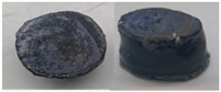
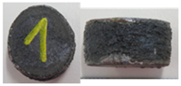
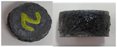
Metals 13 01420 i001Metals 13 01420 i002Metals 13 01420 i003
Table 5. Microstructural details of 4822 material conditions investigated after cyclic heat treatment and water quenching in the compression thermal cycle at 1100 °C, with a 5 min soak.
Phase
Morphology
%lameqfAvg. Lam. Size (μm)
ACCHT Face 139.8060.2228.6
ACCHT Face 233.3066.7190.6
ACCHT + compression thermal cycle Face 1 36.656.56.9183.5
Table 6. Morphology fractions of each material after 50% primary compression at 1100 °C and 0.001 s−1 calculated with OM and EBSD analyses.
4822 Material Condition (s−1)γ Equiaxed Content (%)Lamellar Content (%)Average Lamellar Grain Size (μm) @ 90° to CompressionAverage Lamellar Grain Size (μm) @ 0° to CompressionAverage Lamellar Grain Size (μm)X-DRX (%)
HH 0.001 P155.644.4281.7418.9350.322.6
HH 0.001 P250.549.5181.4409.8295.628.8
ACCHT 0.001 P1 70.829.2147.2297.3222.344.7
ACCHT 0.001 P284.315.786.3255.9171.154.6
FCCHT 0.001 P156.044.0151.1380.8265.935.4
FCCHT 0.001 P255.144.9176.1366.4271.321.9
Table 7. Compression behaviour values, peak flow stress, and strain rate sensitivity (m) of each material condition under secondary compression to 50% at 1100 °C and at 0.001 s−1 over 800 s, at 0.01 s−1 over 80 s, at 0.1 s−1 over 8 s.
Material ConditionHHACCHTFCCHT
Strain Rate (s−1)0.0010.010.10.0010.010.10.0010.010.1
σpfs—peak flow stress (MPa)111.7218.9348.5111.2202.8341.5117.3212.4343.6
m at ε0.1 0.250.250.24
Secondary compression samples
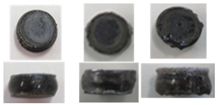
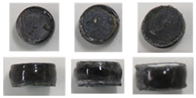
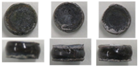
Metals 13 01420 i004Metals 13 01420 i005Metals 13 01420 i006
Table 8. Morphology details for each material after 50% secondary compression at 1100 °C, and 0.001, 0.01, and 0.1 s−1 calculated with OM, BSE, and EBSD analyses.
4822 Material Condition (s−1)Lamellar Content (%)Average Lamellar Grain Size (μm, from 0° and 90°)X-DRX (%)
HH 0.0017.222.147.2
HH 0.0127.846.749.7
HH 0.118.940.331.8
ACCHT 0.0010.00.066.1
ACCHT 0.011.72.347.1
ACCHT 0.19.015.156.7
FCCHT 0.0010.00.058.2
FCCHT 0.010.00.060.1
FCCHT 0.10.00.042.0
Disclaimer/Publisher’s Note: The statements, opinions and data contained in all publications are solely those of the individual author(s) and contributor(s) and not of MDPI and/or the editor(s). MDPI and/or the editor(s) disclaim responsibility for any injury to people or property resulting from any ideas, methods, instructions or products referred to in the content.

